EP2929772A1 - Riding mower with control tamper apparatus - Google Patents
Riding mower with control tamper apparatus Download PDFInfo
- Publication number
- EP2929772A1 EP2929772A1 EP15162531.6A EP15162531A EP2929772A1 EP 2929772 A1 EP2929772 A1 EP 2929772A1 EP 15162531 A EP15162531 A EP 15162531A EP 2929772 A1 EP2929772 A1 EP 2929772A1
- Authority
- EP
- European Patent Office
- Prior art keywords
- riding mower
- control
- switch
- electrical signal
- control unit
- Prior art date
- Legal status (The legal status is an assumption and is not a legal conclusion. Google has not performed a legal analysis and makes no representation as to the accuracy of the status listed.)
- Granted
Links
Images

Classifications
-
- A—HUMAN NECESSITIES
- A01—AGRICULTURE; FORESTRY; ANIMAL HUSBANDRY; HUNTING; TRAPPING; FISHING
- A01D—HARVESTING; MOWING
- A01D34/00—Mowers; Mowing apparatus of harvesters
- A01D34/01—Mowers; Mowing apparatus of harvesters characterised by features relating to the type of cutting apparatus
- A01D34/412—Mowers; Mowing apparatus of harvesters characterised by features relating to the type of cutting apparatus having rotating cutters
- A01D34/63—Mowers; Mowing apparatus of harvesters characterised by features relating to the type of cutting apparatus having rotating cutters having cutters rotating about a vertical axis
- A01D34/82—Other details
- A01D34/828—Safety devices
-
- B—PERFORMING OPERATIONS; TRANSPORTING
- B60—VEHICLES IN GENERAL
- B60N—SEATS SPECIALLY ADAPTED FOR VEHICLES; VEHICLE PASSENGER ACCOMMODATION NOT OTHERWISE PROVIDED FOR
- B60N2/00—Seats specially adapted for vehicles; Arrangement or mounting of seats in vehicles
- B60N2/002—Seats provided with an occupancy detection means mounted therein or thereon
-
- A—HUMAN NECESSITIES
- A01—AGRICULTURE; FORESTRY; ANIMAL HUSBANDRY; HUNTING; TRAPPING; FISHING
- A01D—HARVESTING; MOWING
- A01D75/00—Accessories for harvesters or mowers
- A01D75/18—Safety devices for parts of the machines
-
- B—PERFORMING OPERATIONS; TRANSPORTING
- B60—VEHICLES IN GENERAL
- B60K—ARRANGEMENT OR MOUNTING OF PROPULSION UNITS OR OF TRANSMISSIONS IN VEHICLES; ARRANGEMENT OR MOUNTING OF PLURAL DIVERSE PRIME-MOVERS IN VEHICLES; AUXILIARY DRIVES FOR VEHICLES; INSTRUMENTATION OR DASHBOARDS FOR VEHICLES; ARRANGEMENTS IN CONNECTION WITH COOLING, AIR INTAKE, GAS EXHAUST OR FUEL SUPPLY OF PROPULSION UNITS IN VEHICLES
- B60K28/00—Safety devices for propulsion-unit control, specially adapted for, or arranged in, vehicles, e.g. preventing fuel supply or ignition in the event of potentially dangerous conditions
- B60K28/02—Safety devices for propulsion-unit control, specially adapted for, or arranged in, vehicles, e.g. preventing fuel supply or ignition in the event of potentially dangerous conditions responsive to conditions relating to the driver
- B60K28/04—Safety devices for propulsion-unit control, specially adapted for, or arranged in, vehicles, e.g. preventing fuel supply or ignition in the event of potentially dangerous conditions responsive to conditions relating to the driver responsive to presence or absence of the driver, e.g. to weight or lack thereof
-
- B—PERFORMING OPERATIONS; TRANSPORTING
- B60—VEHICLES IN GENERAL
- B60N—SEATS SPECIALLY ADAPTED FOR VEHICLES; VEHICLE PASSENGER ACCOMMODATION NOT OTHERWISE PROVIDED FOR
- B60N2210/00—Sensor types, e.g. for passenger detection systems or for controlling seats
- B60N2210/40—Force or pressure sensors
- B60N2210/46—Electric switches
-
- B—PERFORMING OPERATIONS; TRANSPORTING
- B60—VEHICLES IN GENERAL
- B60W—CONJOINT CONTROL OF VEHICLE SUB-UNITS OF DIFFERENT TYPE OR DIFFERENT FUNCTION; CONTROL SYSTEMS SPECIALLY ADAPTED FOR HYBRID VEHICLES; ROAD VEHICLE DRIVE CONTROL SYSTEMS FOR PURPOSES NOT RELATED TO THE CONTROL OF A PARTICULAR SUB-UNIT
- B60W2300/00—Indexing codes relating to the type of vehicle
- B60W2300/15—Agricultural vehicles
- B60W2300/156—Ridable lawn mowers
Definitions
- the present invention relates to a riding mower with control tamper apparatus.
- riding mowers are a practically essential tool when cutting large areas, such as for example golf courses or lawns around shopping centres, hospitals, schools, parks, etc., is required.
- motorized riding mowers with (seated) driver on board which are equipped with a metal cutting member comprising one or more cutting elements freely rotating on a pin and mounted on a generally circular drive unit.
- a safety device based on the presence of an operator on the seat is known from Patent MI2008A002159 to this Applicant.
- a safety device Under conditions with cutting elements enabled or mower running, such a safety device is capable of detecting when the operator is no longer present (for example, the operator falls from the mower or simply gets off it) and, in this case, it is configured to force an action such as to ensure a safe condition.
- said safety device comprises a switch located below the driving seat and enclosed, together with the electrical wiring and cabling thereof, inside protective means.
- the switch closes only if there is a pressure given by the weight of the operator thereon and, in this case, the mower normally operates. Otherwise, when the operator is absent, the switch will be open and the safety device will switch off the motor or block the mower blades.
- Tampering often consists in removing the protective means and short-circuiting the contact of the switch (with a clip, a piece of wire or with other conductive objects), thus simulating the presence of the operator driving the mower, even when this is not the case.
- said object is achieved by means of a riding mower comprising at least one driving seat, a safety device which includes a transducer adapted to detect the presence of the operator on the seat and to provide a first electrical signal as a response, and a control unit adapted to manage the movement of the riding mower, said riding mower being characterized in that it comprises a control tamper apparatus configured to convert said first electrical signal into a second electrical signal, and if said second electrical signal is equal to a reference value, to provide said control unit with a control signal as a response.
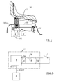
- Figure 1 shows a riding mower 100 according to the present invention.
- the riding mower 100 ( Figs. 1 , 2 ) comprises at least one driving seat 101, a safety device 102 which includes a transducer 2 adapted to detect the presence (or absence) of the operator on seat 101 and to provide a first electrical signal V0 as a response, and a control unit 3 adapted to electronically manage the movement of the riding mower 100.
- the riding mower 100 ( Figs. 2, 3 ) further comprises a control tamper apparatus 1, included in said safety control device 102, said control tamper apparatus being configured to convert said first electrical signal V0 into a second electrical signal V and, if said second electrical signal V is equal to a reference value Vref, to provide said control unit 3 with a control signal STOP as a response.
- said control unit 3 provides for the electronic management of the movement of both the cutting elements (blades) enabled and the running of the riding mower 100.
- said transducer 2 is a switch placed below the driving seat 101 and is closed due to the pressure given by the weight of the operator on seat 101.
- the first electrical signal V0 is the voltage drop across switch 2 and is equal to zero if switch 2 is closed, otherwise have a certain finite value if it is open.
- Switch 2 is further enclosed by protective means 105 which isolate the switch, with its electrical wires and cabling, thus making them inaccessible to the operator in order to avoid any tampering.
- the control tamper apparatus 1 then comprises at least one electrical resistive component R connected in series to said switch 2.
- said at least one electrical resistive component R is a properly calibrated resistor, for example.
- said control tamper apparatus 1 comprises a microcontroller 4 comprising, in turn, at least one input IN adapted to receive said voltage drop V across the series of switch 2 and resistor R, and at least one output OUT adapted to provide, when the voltage drop V is equal to a value of reference voltage Vref, said control unit 3 with a control signal STOP.
- Said microcontroller 4 is configured to detect the voltage drop V across the series of switch 2 and resistor R and, if said voltage drop V is equal to said value of reference voltage Vref, to provide said control unit 3 with a control signal STOP as a response.
- the control signal STOP output from microcontroller 4 is adapted to drive, by means of the control unit 3, the blocking of the movement of the riding mower 100 so as to ensure a safe condition for the operator.
- typical safe conditions may be grounding the spark plug coils, with subsequent switching off of the motor, or blocking the mower blades.
- Vref preferably it is a voltage value equal to zero (or negligible).
- microcontroller 4 included in the control tamper apparatus 1 is configured to recognize the following two normal operating statuses:
- the riding mower 100 according to the present invention normally operates, in the second one, safety measures are implemented on the riding mower 100.
- microcontroller 4 detects the voltage drop V across the series of resistor R and switch 2, while verifying that said voltage drop V is equal to the value of reference voltage Vref (0V). If this check has a positive result, microcontroller 4 sends a control signal STOP to the control unit 3 as a response. This is the case in which microcontroller 4 recognizes a tampering status and keeps the riding mower 100 under safe conditions, by grounding, by means of the control unit 3, the spark plug coils, with the subsequent switching off of the motor, or the blocking of the blades of the riding mower 100. Contrarily, as mentioned, microcontroller 4 continues detecting the voltage drop V and the riding mower 100 continues its normal operation.
- the control tamper apparatus 1 disclosed above will thus be adapted to recognize a tampering status of the switch contact and, in this case, to keep the riding mower under safe conditions.
Landscapes
- Engineering & Computer Science (AREA)
- Transportation (AREA)
- Mechanical Engineering (AREA)
- Aviation & Aerospace Engineering (AREA)
- Chemical & Material Sciences (AREA)
- Combustion & Propulsion (AREA)
- Life Sciences & Earth Sciences (AREA)
- Environmental Sciences (AREA)
- Harvester Elements (AREA)
Abstract
Description
- The present invention relates to a riding mower with control tamper apparatus.
- Within the scope of gardening, riding mowers are a practically essential tool when cutting large areas, such as for example golf courses or lawns around shopping centres, hospitals, schools, parks, etc., is required.
- In particular, motorized riding mowers with (seated) driver on board are known, which are equipped with a metal cutting member comprising one or more cutting elements freely rotating on a pin and mounted on a generally circular drive unit.
- It is known from current legislation that the absence of the operator blocks certain utilities such as the motor; for example, if the operator leaves the seat of the mower, safety regulations provide for the motor to be automatically switched off and therefore the mower and the blades stop within the provided space/time limits.
- For example, a safety device based on the presence of an operator on the seat is known from Patent MI2008A002159 to this Applicant. Under conditions with cutting elements enabled or mower running, such a safety device is capable of detecting when the operator is no longer present (for example, the operator falls from the mower or simply gets off it) and, in this case, it is configured to force an action such as to ensure a safe condition.
- In particular, said safety device comprises a switch located below the driving seat and enclosed, together with the electrical wiring and cabling thereof, inside protective means. In operation, the switch closes only if there is a pressure given by the weight of the operator thereon and, in this case, the mower normally operates. Otherwise, when the operator is absent, the switch will be open and the safety device will switch off the motor or block the mower blades.
- However, on the market, the safety of the system is increasingly often tampered with and thus excluded. Tampering often consists in removing the protective means and short-circuiting the contact of the switch (with a clip, a piece of wire or with other conductive objects), thus simulating the presence of the operator driving the mower, even when this is not the case.
- In view of the state of the art, it is the object of the present invention to provide a riding mower with an apparatus adapted to recognize a tampering status of the safety device and, in this case, to keep the riding mower under safe conditions.
- In accordance with the present invention, said object is achieved by means of a riding mower comprising at least one driving seat, a safety device which includes a transducer adapted to detect the presence of the operator on the seat and to provide a first electrical signal as a response, and a control unit adapted to manage the movement of the riding mower, said riding mower being characterized in that it comprises a control tamper apparatus configured to convert said first electrical signal into a second electrical signal, and if said second electrical signal is equal to a reference value, to provide said control unit with a control signal as a response.
- The features and advantages of the present invention will become apparent from the following detailed description of a practical embodiment thereof, shown by way of non-limiting example in the accompanying drawings, in which:
-
figure 1 shows a riding mower according to the present invention; -
figure 2 shows a detail of the riding mower infigure 1 ; -
figure 3 shows a circuit block diagram of a control tamper apparatus included in the riding mower infigure 1 . -
Figure 1 shows ariding mower 100 according to the present invention. - The riding mower 100 (
Figs. 1 ,2 ) comprises at least onedriving seat 101, asafety device 102 which includes atransducer 2 adapted to detect the presence (or absence) of the operator onseat 101 and to provide a first electrical signal V0 as a response, and acontrol unit 3 adapted to electronically manage the movement of theriding mower 100. - The riding mower 100 (
Figs. 2, 3 ) further comprises acontrol tamper apparatus 1, included in saidsafety control device 102, said control tamper apparatus being configured to convert said first electrical signal V0 into a second electrical signal V and, if said second electrical signal V is equal to a reference value Vref, to provide saidcontrol unit 3 with a control signal STOP as a response. - In this case, said
control unit 3 provides for the electronic management of the movement of both the cutting elements (blades) enabled and the running of theriding mower 100. - Preferably, said
transducer 2 is a switch placed below thedriving seat 101 and is closed due to the pressure given by the weight of the operator onseat 101. In this case, the first electrical signal V0 is the voltage drop acrossswitch 2 and is equal to zero ifswitch 2 is closed, otherwise have a certain finite value if it is open.Switch 2 is further enclosed byprotective means 105 which isolate the switch, with its electrical wires and cabling, thus making them inaccessible to the operator in order to avoid any tampering. Thecontrol tamper apparatus 1 then comprises at least one electrical resistive component R connected in series to saidswitch 2. - Preferably, said at least one electrical resistive component R is a properly calibrated resistor, for example.
- Moreover, said
control tamper apparatus 1 comprises amicrocontroller 4 comprising, in turn, at least one input IN adapted to receive said voltage drop V across the series ofswitch 2 and resistor R, and at least one output OUT adapted to provide, when the voltage drop V is equal to a value of reference voltage Vref, saidcontrol unit 3 with a control signal STOP. - Said
microcontroller 4 is configured to detect the voltage drop V across the series ofswitch 2 and resistor R and, if said voltage drop V is equal to said value of reference voltage Vref, to provide saidcontrol unit 3 with a control signal STOP as a response. - The control signal STOP output from
microcontroller 4 is adapted to drive, by means of thecontrol unit 3, the blocking of the movement of theriding mower 100 so as to ensure a safe condition for the operator. For example, typical safe conditions may be grounding the spark plug coils, with subsequent switching off of the motor, or blocking the mower blades. - With regard to said value of reference voltage Vref, preferably it is a voltage value equal to zero (or negligible). This explains why old safety devices, which included only the switch, operated by recognizing two statuses:
- "operator present", with the switch closed (voltage equal to zero across the switch);
- "operator absent", with the switch open (finite voltage across the switch);
- In the first case, the mower continued operating normally, in the second case safety measures were implemented on the riding mower.
- This is why the most common tampering aims to short-circuit the accessible terminals of the old switch (which in other terms is equivalent to the voltage value 0V), so that the old safety device recognizes the "operator present" status and continues operating despite the operator not actually being present, thus representing a hazardous condition for the same.
- Otherwise,
microcontroller 4, included in thecontrol tamper apparatus 1, is configured to recognize the following two normal operating statuses: - "operator present", with
switch 2 closed and a voltage drop V across the series of resistor R and switch 2 equal to V0+VR=0+ VR=VR, which is the voltage drop on resistor R; - "operator absent", with
switch 2 open and a finite voltage drop V equal to V0+Vr across the series of resistor R andswitch 2. - In the first case, the
riding mower 100 according to the present invention normally operates, in the second one, safety measures are implemented on theriding mower 100. - Since the accessible terminals of the
safety system 102 are said ends of the series of resistor R andswitch 2, it is easy to understand that in this case tampering with short-circuiting of the terminals will cause a status which does not fall under one of the previous two, that is: - "hazardous status", with a voltage drop V across the series of resistor R and
switch 2 equal to 0V (Vref) which will be recognized bymicrocontroller 4 in the same way as the "operator absent" status, thus implementing safety measures on theriding mower 100. - In operation,
microcontroller 4 detects the voltage drop V across the series of resistor R andswitch 2, while verifying that said voltage drop V is equal to the value of reference voltage Vref (0V). If this check has a positive result,microcontroller 4 sends a control signal STOP to thecontrol unit 3 as a response. This is the case in whichmicrocontroller 4 recognizes a tampering status and keeps theriding mower 100 under safe conditions, by grounding, by means of thecontrol unit 3, the spark plug coils, with the subsequent switching off of the motor, or the blocking of the blades of theriding mower 100. Contrarily, as mentioned,microcontroller 4 continues detecting the voltage drop V and theriding mower 100 continues its normal operation. - The
control tamper apparatus 1 disclosed above will thus be adapted to recognize a tampering status of the switch contact and, in this case, to keep the riding mower under safe conditions.
Claims (6)
- Riding mower (100) comprising at least one driving seat (101), a safety device (102) which comprise a transducer (2) adapted to detect the presence of the operator on the driving seat (101) and to provide, as a response, a first electrical signal (V0), and a control unit (3) configured for the electronic management of the movement of the riding mower (100), said riding mower (100) being characterized by comprising a control tamper apparatus (1) configured for converting said first electrical signal (V0) in a second electrical signal (V) and, if said second electrical signal (V) is equal to a reference value (Vref), as a response provide a control signal (STOP) to said control unit (3).
- Riding mower (100) according to claim 1, characterized in that said control tamper apparatus (1) comprises a microcontroller (4) in turn comprising at least one input (IN) configured to receive said second electrical signal (V), and at least one output (OUT) configured to provide said control signal (STOP) to said control unit (3).
- Riding mower (100) according to any one of claims 1-2, characterized in that said control signal (STOP) is suitable to drive by means of the control unit (3) the blocking of the movement of the riding mower (100) for ensure a safe condition for the operator.
- Riding mower (100) according to claim 1, characterized in that said transducer (2) is a switch, and in that said control tamper apparatus (1) comprises at least one electrical resistive component (R) connected in series with said switch (2), said control tamper apparatus (1) being configured to detect the voltage drop (V) across the series of the switch (2) and the at least one electrical resistive component (R) and, if said voltage drop (V) is equal to a reference value (Vref) to provide, as a response, said control signal (STOP) to said control unit (3).
- Riding mower (100) according to claim 4, characterized in that said at least one electrical resistive component (R) is a resistor properly calibrated.
- Riding mower (100) according to claim 4, characterized in that said value of the reference voltage (Vref) is a voltage value equal to zero (or negligible).
Applications Claiming Priority (1)
| Application Number | Priority Date | Filing Date | Title |
|---|---|---|---|
| ITMI20140663 | 2014-04-09 |
Publications (2)
| Publication Number | Publication Date |
|---|---|
| EP2929772A1 true EP2929772A1 (en) | 2015-10-14 |
| EP2929772B1 EP2929772B1 (en) | 2016-11-23 |
Family
ID=51179005
Family Applications (1)
| Application Number | Title | Priority Date | Filing Date |
|---|---|---|---|
| EP15162531.6A Active EP2929772B1 (en) | 2014-04-09 | 2015-04-07 | Riding mower with control tamper apparatus |
Country Status (1)
| Country | Link |
|---|---|
| EP (1) | EP2929772B1 (en) |
Cited By (1)
| Publication number | Priority date | Publication date | Assignee | Title |
|---|---|---|---|---|
| EP3653038A1 (en) * | 2018-11-16 | 2020-05-20 | Changzhou Globe Co., Ltd. | A lawn mower |
Citations (5)
| Publication number | Priority date | Publication date | Assignee | Title |
|---|---|---|---|---|
| FR2328082A1 (en) * | 1975-10-15 | 1977-05-13 | Hokushin Electric Works | PERFECTED CONTROL SYSTEM FOR EXTRACTION MACHINES, SUCH AS FOR EXAMPLE MECHANICAL SHOVELS |
| EP0328341A1 (en) * | 1988-02-10 | 1989-08-16 | FORD NEW HOLLAND, INC. (a Delaware corp.) | Seat belt interlock for loaders |
| US6092838A (en) * | 1998-04-06 | 2000-07-25 | Walker; Robert R. | System and method for determining the weight of a person in a seat in a vehicle |
| US20040090338A1 (en) * | 2002-11-11 | 2004-05-13 | Kubota Corporation | Operator presence sensing apparatus for a seat of a vehicle |
| ITMI20082159A1 (en) | 2008-12-05 | 2010-06-06 | Ggp Italy Spa | SAFETY DEVICE CONNECTED TO THE PRESENCE OF THE OPERATOR ON THE SEAT OF A TRACTOR |
-
2015
- 2015-04-07 EP EP15162531.6A patent/EP2929772B1/en active Active
Patent Citations (6)
| Publication number | Priority date | Publication date | Assignee | Title |
|---|---|---|---|---|
| FR2328082A1 (en) * | 1975-10-15 | 1977-05-13 | Hokushin Electric Works | PERFECTED CONTROL SYSTEM FOR EXTRACTION MACHINES, SUCH AS FOR EXAMPLE MECHANICAL SHOVELS |
| EP0328341A1 (en) * | 1988-02-10 | 1989-08-16 | FORD NEW HOLLAND, INC. (a Delaware corp.) | Seat belt interlock for loaders |
| US6092838A (en) * | 1998-04-06 | 2000-07-25 | Walker; Robert R. | System and method for determining the weight of a person in a seat in a vehicle |
| US20040090338A1 (en) * | 2002-11-11 | 2004-05-13 | Kubota Corporation | Operator presence sensing apparatus for a seat of a vehicle |
| ITMI20082159A1 (en) | 2008-12-05 | 2010-06-06 | Ggp Italy Spa | SAFETY DEVICE CONNECTED TO THE PRESENCE OF THE OPERATOR ON THE SEAT OF A TRACTOR |
| EP2193703A1 (en) * | 2008-12-05 | 2010-06-09 | GGP Italy S.p.A. | Safety device based on a presence of the operator on the seat of a tractor |
Cited By (1)
| Publication number | Priority date | Publication date | Assignee | Title |
|---|---|---|---|---|
| EP3653038A1 (en) * | 2018-11-16 | 2020-05-20 | Changzhou Globe Co., Ltd. | A lawn mower |
Also Published As
| Publication number | Publication date |
|---|---|
| EP2929772B1 (en) | 2016-11-23 |
Similar Documents
| Publication | Publication Date | Title |
|---|---|---|
| DE3153749C2 (en) | Disconnector with test options | |
| EP3444834B1 (en) | Electronic status reporting circuit breaker | |
| US20090225480A1 (en) | Electrical Safety Outlet | |
| MX2015000608A (en) | Self-test gfci device with dual solenoid coil electric control. | |
| JPH05240882A (en) | Fault circuit detector provided with insulated indicator | |
| JP2009055657A5 (en) | ||
| CN107219437B (en) | High-voltage interlocking detection circuit, method and device and automobile | |
| CN104901283A (en) | Method and apparatus for selective insulation monitoring in unearthed IT power supply systems | |
| CN102720595A (en) | Engine overspeed protection and control method | |
| KR101735869B1 (en) | Apparatus for Detecting Surge Voltage using Shunt Regulator | |
| CN107359586B (en) | Method for protecting a working machine and working machine | |
| EP1731915A1 (en) | Arc fault circuit interrupter test circuit | |
| US20180005542A1 (en) | High Voltage Training Device and System and Method Thereof | |
| EP2929772B1 (en) | Riding mower with control tamper apparatus | |
| CN104053568B (en) | For monitoring method and the equipment of high-tension unit | |
| CN101876684B (en) | Failure detecting and protecting method of controlled silicon and device thereof | |
| US6633471B1 (en) | Overcurrent protection circuit, electric leakage protection circuit for an electric apparatus | |
| KR101062313B1 (en) | Automatic recovery type earth leakage breaker | |
| CN105429196B (en) | The monitoring of conductor is protected during the charging process | |
| CN101271787B (en) | Device and method for automatic recognition and differentiation of electronic sensors connected to safety combination | |
| US8884557B2 (en) | Disconnection from mains using switches for power tools | |
| CN107017603A (en) | Smart grounding protection device and its control method | |
| CN212627152U (en) | System for monitoring the condition of a surge arrester | |
| CN2821983Y (en) | Current-limiting protection circuit for power supplies | |
| JP2004512646A (en) | Low voltage circuit breaker with rating plug |
Legal Events
| Date | Code | Title | Description |
|---|---|---|---|
| PUAI | Public reference made under article 153(3) epc to a published international application that has entered the european phase |
Free format text: ORIGINAL CODE: 0009012 |
|
| AK | Designated contracting states |
Kind code of ref document: A1 Designated state(s): AL AT BE BG CH CY CZ DE DK EE ES FI FR GB GR HR HU IE IS IT LI LT LU LV MC MK MT NL NO PL PT RO RS SE SI SK SM TR |
|
| AX | Request for extension of the european patent |
Extension state: BA ME |
|
| 17P | Request for examination filed |
Effective date: 20160404 |
|
| RBV | Designated contracting states (corrected) |
Designated state(s): AL AT BE BG CH CY CZ DE DK EE ES FI FR GB GR HR HU IE IS IT LI LT LU LV MC MK MT NL NO PL PT RO RS SE SI SK SM TR |
|
| GRAP | Despatch of communication of intention to grant a patent |
Free format text: ORIGINAL CODE: EPIDOSNIGR1 |
|
| INTG | Intention to grant announced |
Effective date: 20160621 |
|
| GRAS | Grant fee paid |
Free format text: ORIGINAL CODE: EPIDOSNIGR3 |
|
| GRAA | (expected) grant |
Free format text: ORIGINAL CODE: 0009210 |
|
| AK | Designated contracting states |
Kind code of ref document: B1 Designated state(s): AL AT BE BG CH CY CZ DE DK EE ES FI FR GB GR HR HU IE IS IT LI LT LU LV MC MK MT NL NO PL PT RO RS SE SI SK SM TR |
|
| REG | Reference to a national code |
Ref country code: GB Ref legal event code: FG4D |
|
| REG | Reference to a national code |
Ref country code: CH Ref legal event code: EP |
|
| REG | Reference to a national code |
Ref country code: IE Ref legal event code: FG4D |
|
| REG | Reference to a national code |
Ref country code: AT Ref legal event code: REF Ref document number: 846989 Country of ref document: AT Kind code of ref document: T Effective date: 20161215 |
|
| REG | Reference to a national code |
Ref country code: DE Ref legal event code: R096 Ref document number: 602015000777 Country of ref document: DE |
|
| REG | Reference to a national code |
Ref country code: FR Ref legal event code: PLFP Year of fee payment: 3 |
|
| PG25 | Lapsed in a contracting state [announced via postgrant information from national office to epo] |
Ref country code: LV Free format text: LAPSE BECAUSE OF FAILURE TO SUBMIT A TRANSLATION OF THE DESCRIPTION OR TO PAY THE FEE WITHIN THE PRESCRIBED TIME-LIMIT Effective date: 20161123 |
|
| REG | Reference to a national code |
Ref country code: SE Ref legal event code: TRGR |
|
| REG | Reference to a national code |
Ref country code: LT Ref legal event code: MG4D |
|
| REG | Reference to a national code |
Ref country code: NL Ref legal event code: MP Effective date: 20161123 |
|
| REG | Reference to a national code |
Ref country code: AT Ref legal event code: MK05 Ref document number: 846989 Country of ref document: AT Kind code of ref document: T Effective date: 20161123 |
|
| PG25 | Lapsed in a contracting state [announced via postgrant information from national office to epo] |
Ref country code: NL Free format text: LAPSE BECAUSE OF FAILURE TO SUBMIT A TRANSLATION OF THE DESCRIPTION OR TO PAY THE FEE WITHIN THE PRESCRIBED TIME-LIMIT Effective date: 20161123 Ref country code: LT Free format text: LAPSE BECAUSE OF FAILURE TO SUBMIT A TRANSLATION OF THE DESCRIPTION OR TO PAY THE FEE WITHIN THE PRESCRIBED TIME-LIMIT Effective date: 20161123 Ref country code: GR Free format text: LAPSE BECAUSE OF FAILURE TO SUBMIT A TRANSLATION OF THE DESCRIPTION OR TO PAY THE FEE WITHIN THE PRESCRIBED TIME-LIMIT Effective date: 20170224 Ref country code: NO Free format text: LAPSE BECAUSE OF FAILURE TO SUBMIT A TRANSLATION OF THE DESCRIPTION OR TO PAY THE FEE WITHIN THE PRESCRIBED TIME-LIMIT Effective date: 20170223 |
|
| PG25 | Lapsed in a contracting state [announced via postgrant information from national office to epo] |
Ref country code: HR Free format text: LAPSE BECAUSE OF FAILURE TO SUBMIT A TRANSLATION OF THE DESCRIPTION OR TO PAY THE FEE WITHIN THE PRESCRIBED TIME-LIMIT Effective date: 20161123 Ref country code: RS Free format text: LAPSE BECAUSE OF FAILURE TO SUBMIT A TRANSLATION OF THE DESCRIPTION OR TO PAY THE FEE WITHIN THE PRESCRIBED TIME-LIMIT Effective date: 20161123 Ref country code: PT Free format text: LAPSE BECAUSE OF FAILURE TO SUBMIT A TRANSLATION OF THE DESCRIPTION OR TO PAY THE FEE WITHIN THE PRESCRIBED TIME-LIMIT Effective date: 20170323 Ref country code: PL Free format text: LAPSE BECAUSE OF FAILURE TO SUBMIT A TRANSLATION OF THE DESCRIPTION OR TO PAY THE FEE WITHIN THE PRESCRIBED TIME-LIMIT Effective date: 20161123 Ref country code: AT Free format text: LAPSE BECAUSE OF FAILURE TO SUBMIT A TRANSLATION OF THE DESCRIPTION OR TO PAY THE FEE WITHIN THE PRESCRIBED TIME-LIMIT Effective date: 20161123 Ref country code: ES Free format text: LAPSE BECAUSE OF FAILURE TO SUBMIT A TRANSLATION OF THE DESCRIPTION OR TO PAY THE FEE WITHIN THE PRESCRIBED TIME-LIMIT Effective date: 20161123 Ref country code: FI Free format text: LAPSE BECAUSE OF FAILURE TO SUBMIT A TRANSLATION OF THE DESCRIPTION OR TO PAY THE FEE WITHIN THE PRESCRIBED TIME-LIMIT Effective date: 20161123 |
|
| PG25 | Lapsed in a contracting state [announced via postgrant information from national office to epo] |
Ref country code: RO Free format text: LAPSE BECAUSE OF FAILURE TO SUBMIT A TRANSLATION OF THE DESCRIPTION OR TO PAY THE FEE WITHIN THE PRESCRIBED TIME-LIMIT Effective date: 20161123 Ref country code: DK Free format text: LAPSE BECAUSE OF FAILURE TO SUBMIT A TRANSLATION OF THE DESCRIPTION OR TO PAY THE FEE WITHIN THE PRESCRIBED TIME-LIMIT Effective date: 20161123 Ref country code: EE Free format text: LAPSE BECAUSE OF FAILURE TO SUBMIT A TRANSLATION OF THE DESCRIPTION OR TO PAY THE FEE WITHIN THE PRESCRIBED TIME-LIMIT Effective date: 20161123 Ref country code: SK Free format text: LAPSE BECAUSE OF FAILURE TO SUBMIT A TRANSLATION OF THE DESCRIPTION OR TO PAY THE FEE WITHIN THE PRESCRIBED TIME-LIMIT Effective date: 20161123 Ref country code: CZ Free format text: LAPSE BECAUSE OF FAILURE TO SUBMIT A TRANSLATION OF THE DESCRIPTION OR TO PAY THE FEE WITHIN THE PRESCRIBED TIME-LIMIT Effective date: 20161123 |
|
| REG | Reference to a national code |
Ref country code: DE Ref legal event code: R097 Ref document number: 602015000777 Country of ref document: DE |
|
| PG25 | Lapsed in a contracting state [announced via postgrant information from national office to epo] |
Ref country code: BE Free format text: LAPSE BECAUSE OF FAILURE TO SUBMIT A TRANSLATION OF THE DESCRIPTION OR TO PAY THE FEE WITHIN THE PRESCRIBED TIME-LIMIT Effective date: 20161123 Ref country code: SM Free format text: LAPSE BECAUSE OF FAILURE TO SUBMIT A TRANSLATION OF THE DESCRIPTION OR TO PAY THE FEE WITHIN THE PRESCRIBED TIME-LIMIT Effective date: 20161123 Ref country code: BG Free format text: LAPSE BECAUSE OF FAILURE TO SUBMIT A TRANSLATION OF THE DESCRIPTION OR TO PAY THE FEE WITHIN THE PRESCRIBED TIME-LIMIT Effective date: 20170223 |
|
| PLBE | No opposition filed within time limit |
Free format text: ORIGINAL CODE: 0009261 |
|
| STAA | Information on the status of an ep patent application or granted ep patent |
Free format text: STATUS: NO OPPOSITION FILED WITHIN TIME LIMIT |
|
| 26N | No opposition filed |
Effective date: 20170824 |
|
| PG25 | Lapsed in a contracting state [announced via postgrant information from national office to epo] |
Ref country code: SI Free format text: LAPSE BECAUSE OF FAILURE TO SUBMIT A TRANSLATION OF THE DESCRIPTION OR TO PAY THE FEE WITHIN THE PRESCRIBED TIME-LIMIT Effective date: 20161123 |
|
| REG | Reference to a national code |
Ref country code: IE Ref legal event code: MM4A |
|
| PG25 | Lapsed in a contracting state [announced via postgrant information from national office to epo] |
Ref country code: MC Free format text: LAPSE BECAUSE OF FAILURE TO SUBMIT A TRANSLATION OF THE DESCRIPTION OR TO PAY THE FEE WITHIN THE PRESCRIBED TIME-LIMIT Effective date: 20161123 |
|
| PG25 | Lapsed in a contracting state [announced via postgrant information from national office to epo] |
Ref country code: LU Free format text: LAPSE BECAUSE OF NON-PAYMENT OF DUE FEES Effective date: 20170407 |
|
| REG | Reference to a national code |
Ref country code: FR Ref legal event code: PLFP Year of fee payment: 4 |
|
| PG25 | Lapsed in a contracting state [announced via postgrant information from national office to epo] |
Ref country code: IE Free format text: LAPSE BECAUSE OF NON-PAYMENT OF DUE FEES Effective date: 20170407 |
|
| PG25 | Lapsed in a contracting state [announced via postgrant information from national office to epo] |
Ref country code: MT Free format text: LAPSE BECAUSE OF NON-PAYMENT OF DUE FEES Effective date: 20170407 |
|
| REG | Reference to a national code |
Ref country code: CH Ref legal event code: PL |
|
| PG25 | Lapsed in a contracting state [announced via postgrant information from national office to epo] |
Ref country code: CH Free format text: LAPSE BECAUSE OF NON-PAYMENT OF DUE FEES Effective date: 20180430 Ref country code: LI Free format text: LAPSE BECAUSE OF NON-PAYMENT OF DUE FEES Effective date: 20180430 |
|
| PG25 | Lapsed in a contracting state [announced via postgrant information from national office to epo] |
Ref country code: HU Free format text: LAPSE BECAUSE OF FAILURE TO SUBMIT A TRANSLATION OF THE DESCRIPTION OR TO PAY THE FEE WITHIN THE PRESCRIBED TIME-LIMIT; INVALID AB INITIO Effective date: 20150407 |
|
| PG25 | Lapsed in a contracting state [announced via postgrant information from national office to epo] |
Ref country code: CY Free format text: LAPSE BECAUSE OF FAILURE TO SUBMIT A TRANSLATION OF THE DESCRIPTION OR TO PAY THE FEE WITHIN THE PRESCRIBED TIME-LIMIT Effective date: 20161123 |
|
| PG25 | Lapsed in a contracting state [announced via postgrant information from national office to epo] |
Ref country code: MK Free format text: LAPSE BECAUSE OF FAILURE TO SUBMIT A TRANSLATION OF THE DESCRIPTION OR TO PAY THE FEE WITHIN THE PRESCRIBED TIME-LIMIT Effective date: 20161123 |
|
| PG25 | Lapsed in a contracting state [announced via postgrant information from national office to epo] |
Ref country code: TR Free format text: LAPSE BECAUSE OF FAILURE TO SUBMIT A TRANSLATION OF THE DESCRIPTION OR TO PAY THE FEE WITHIN THE PRESCRIBED TIME-LIMIT Effective date: 20161123 |
|
| PG25 | Lapsed in a contracting state [announced via postgrant information from national office to epo] |
Ref country code: AL Free format text: LAPSE BECAUSE OF FAILURE TO SUBMIT A TRANSLATION OF THE DESCRIPTION OR TO PAY THE FEE WITHIN THE PRESCRIBED TIME-LIMIT Effective date: 20161123 Ref country code: IS Free format text: LAPSE BECAUSE OF FAILURE TO SUBMIT A TRANSLATION OF THE DESCRIPTION OR TO PAY THE FEE WITHIN THE PRESCRIBED TIME-LIMIT Effective date: 20170323 |
|
| P01 | Opt-out of the competence of the unified patent court (upc) registered |
Effective date: 20230421 |
|
| PGFP | Annual fee paid to national office [announced via postgrant information from national office to epo] |
Ref country code: DE Payment date: 20250429 Year of fee payment: 11 |
|
| PGFP | Annual fee paid to national office [announced via postgrant information from national office to epo] |
Ref country code: FR Payment date: 20250401 Year of fee payment: 11 |
|
| PGFP | Annual fee paid to national office [announced via postgrant information from national office to epo] |
Ref country code: SE Payment date: 20250417 Year of fee payment: 11 |
|
| PGFP | Annual fee paid to national office [announced via postgrant information from national office to epo] |
Ref country code: GB Payment date: 20260325 Year of fee payment: 12 |
|
| PGFP | Annual fee paid to national office [announced via postgrant information from national office to epo] |
Ref country code: IT Payment date: 20260324 Year of fee payment: 12 |