EP2929242B1 - Electrode boiler with electrodes unit - Google Patents
Electrode boiler with electrodes unit Download PDFInfo
- Publication number
- EP2929242B1 EP2929242B1 EP12889526.5A EP12889526A EP2929242B1 EP 2929242 B1 EP2929242 B1 EP 2929242B1 EP 12889526 A EP12889526 A EP 12889526A EP 2929242 B1 EP2929242 B1 EP 2929242B1
- Authority
- EP
- European Patent Office
- Prior art keywords
- electrode
- electrodes
- boiler
- case
- unit according
- Prior art date
- Legal status (The legal status is an assumption and is not a legal conclusion. Google has not performed a legal analysis and makes no representation as to the accuracy of the status listed.)
- Active
Links
Images



Classifications
-
- F—MECHANICAL ENGINEERING; LIGHTING; HEATING; WEAPONS; BLASTING
- F22—STEAM GENERATION
- F22B—METHODS OF STEAM GENERATION; STEAM BOILERS
- F22B1/00—Methods of steam generation characterised by form of heating method
- F22B1/28—Methods of steam generation characterised by form of heating method in boilers heated electrically
- F22B1/30—Electrode boilers
-
- F—MECHANICAL ENGINEERING; LIGHTING; HEATING; WEAPONS; BLASTING
- F24—HEATING; RANGES; VENTILATING
- F24H—FLUID HEATERS, e.g. WATER OR AIR HEATERS, HAVING HEAT-GENERATING MEANS, e.g. HEAT PUMPS, IN GENERAL
- F24H1/00—Water heaters, e.g. boilers, continuous-flow heaters or water-storage heaters
- F24H1/18—Water-storage heaters
- F24H1/20—Water-storage heaters with immersed heating elements, e.g. electric elements or furnace tubes
- F24H1/201—Water-storage heaters with immersed heating elements, e.g. electric elements or furnace tubes using electric energy supply
- F24H1/203—Water-storage heaters with immersed heating elements, e.g. electric elements or furnace tubes using electric energy supply with electrodes
-
- F—MECHANICAL ENGINEERING; LIGHTING; HEATING; WEAPONS; BLASTING
- F24—HEATING; RANGES; VENTILATING
- F24H—FLUID HEATERS, e.g. WATER OR AIR HEATERS, HAVING HEAT-GENERATING MEANS, e.g. HEAT PUMPS, IN GENERAL
- F24H9/00—Details
- F24H9/18—Arrangement or mounting of grates or heating means
- F24H9/1809—Arrangement or mounting of grates or heating means for water heaters
- F24H9/1818—Arrangement or mounting of electric heating means
-
- F—MECHANICAL ENGINEERING; LIGHTING; HEATING; WEAPONS; BLASTING
- F24—HEATING; RANGES; VENTILATING
- F24H—FLUID HEATERS, e.g. WATER OR AIR HEATERS, HAVING HEAT-GENERATING MEANS, e.g. HEAT PUMPS, IN GENERAL
- F24H9/00—Details
- F24H9/40—Arrangements for preventing corrosion
- F24H9/45—Arrangements for preventing corrosion for preventing galvanic corrosion, e.g. cathodic or electrolytic means
- F24H9/455—Arrangements for preventing corrosion for preventing galvanic corrosion, e.g. cathodic or electrolytic means for water heaters
-
- H—ELECTRICITY
- H05—ELECTRIC TECHNIQUES NOT OTHERWISE PROVIDED FOR
- H05B—ELECTRIC HEATING; ELECTRIC LIGHT SOURCES NOT OTHERWISE PROVIDED FOR; CIRCUIT ARRANGEMENTS FOR ELECTRIC LIGHT SOURCES, IN GENERAL
- H05B3/00—Ohmic-resistance heating
- H05B3/0004—Devices wherein the heating current flows through the material to be heated
- H05B3/0009—Devices wherein the heating current flows through the material to be heated the material to be heated being in motion
-
- H—ELECTRICITY
- H05—ELECTRIC TECHNIQUES NOT OTHERWISE PROVIDED FOR
- H05B—ELECTRIC HEATING; ELECTRIC LIGHT SOURCES NOT OTHERWISE PROVIDED FOR; CIRCUIT ARRANGEMENTS FOR ELECTRIC LIGHT SOURCES, IN GENERAL
- H05B3/00—Ohmic-resistance heating
- H05B3/02—Details
- H05B3/03—Electrodes
-
- H—ELECTRICITY
- H05—ELECTRIC TECHNIQUES NOT OTHERWISE PROVIDED FOR
- H05B—ELECTRIC HEATING; ELECTRIC LIGHT SOURCES NOT OTHERWISE PROVIDED FOR; CIRCUIT ARRANGEMENTS FOR ELECTRIC LIGHT SOURCES, IN GENERAL
- H05B3/00—Ohmic-resistance heating
- H05B3/60—Heating arrangements wherein the heating current flows through granular powdered or fluid material, e.g. for salt-bath furnace, electrolytic heating
-
- F—MECHANICAL ENGINEERING; LIGHTING; HEATING; WEAPONS; BLASTING
- F24—HEATING; RANGES; VENTILATING
- F24H—FLUID HEATERS, e.g. WATER OR AIR HEATERS, HAVING HEAT-GENERATING MEANS, e.g. HEAT PUMPS, IN GENERAL
- F24H2250/00—Electrical heat generating means
- F24H2250/10—Electrodes
Definitions
- the invention relates to heat engineering, power engineering and the field of electric heating of liquids, water for instance, steam generation, direct conversion of electric energy into heat energy; it can be used in circulation water heating systems, self-regulating liquid heaters for autonomous heating and hot water supply, mobile heating and hot water supply, and as a universal device for diverse electric heaters.
- Electrode water heating boilers are designed to provide hot water and steam at the expense of heat released by electric current (single- or three-phase one) directly flowing through water.
- Boilers are used for heating and hot water supply of production and residential spaces, in open as well as close heating systems. They are also used at industrial plants, agricultural plants, and any other facilities which manufacturing processes require hot water of 95... 100 Celsius degrees.
- the simple design, high reliability, service life, efficiency, and fabricability in mass production as well as the ability of full automation and unattended operation present great advantages of electrode boilers. Their merits also include the potential relative easiness of maintenance of accurate temperature conditions in heated spaces and related to it saving of primary energy resources by consumers. Boilers became proliferated due to those reasons. They also can be used in parallel as hot water circulating pumps.
- An object of the invention is to enhance the ease of fabrication, fabricability, and operability for multiple electrodes and electrode heating boilers on the whole.
- the invention also aims to improve the design reliability for the device in question, its protection against assembling inaccuracies, to bate requirements to the accuracy of installation of electrodes inside the case and their orientation against each other inclusive of various operating conditions, i.e., both static and dynamic ones.
- the invention seeks to increase the live of device, its service life period, maintainability and reparability.
- the invention meets an object of extended performance capabilities, versatility and flexibility of the device, potential diversification and enhancement of adaptability in solving particular problems.
- the invention allows improvement of convection in water heating boilers and reduction of uniformity of sludge and rust deposition on electrodes thus increasing the heater effective performance time.
- the invention object comprises an improvement of protection against breakdowns between the electrodes as well, phase current load imbalance reduction, electrode protection against non-uniform deformation during operation in dynamic conditions. It is also an object of the invention to extend the range of constructional capacity control without design and dimensional changes.
- the electrode boiler with multiple electrode shall comprise a case, multiple electrode in the form of fastened inside the case rod electrodes, at least one; the electrodes shall be arranged non-symmetrically relative to the case symmetric axes and to each other; electrode longitudinal axes not coinciding with the case longitudinal axes, electrode longitudinal axes not coinciding with the case transverse axes and electrodes having external terminals brought out from the case outside.
- the multiple electrode shall also comprise at least one electrode basis.
- the electrode boiler basis shall be implemented in the form of a plate, electrodes being fastened to the plate on one side of its first surface so that their longitudinal axes are arranged in the direction close to the normal one with respect to the first plate surface; electrode basis being fastened with the second surface on the inner side of the case.
- the basis may be implemented of electrically insulating heat-resistant material.
- the electrode basis may be implemented of metal.
- the electrode basis is fastened with the second plane on the inner case side so that electrode ends are directed inside the internal boiler space.
- the electrode basis is fastened with the second plane on the inner side of the upper half-case so that electrode ends are directed inside the internal boiler space downwards.
- the electrode basis is fastened with the second plane on the inner side of the upper half-case so that free electrode ends are directed inside the internal boiler space laterally.
- the electrode basis is fastened with its second plane on the inner side of the lower half-case so that free electrode ends are directed inside the internal boiler space upwards.
- the electrode basis is fastened with one its plane on the outer case side so that electrode ends are directed inside the internal boiler space.
- the electrode basis is fastened with the first plane on the outer side of the upper half-case so that electrode ends are directed inside the internal boiler space downwards.
- the electrode basis is fastened with the first plane on the outer side of the upper half-case so that free electrode ends are directed inside the internal boiler space laterally.
- the electrode basis is fastened with its first plane on the outer side of the lower half-case so that free electrode ends are directed inside the internal boiler space upwards.
- the electrode boiler comprises insulating bushings implemented in the form of cylindrical tubes, superposed on the first electrode ends and connected to the basis until they rest in the basis; the bushings being constructively sunk, at least partially, in the basis; the height of bushings may vary.
- the height of bushings may vary equally for all the electrodes.
- the height of bushings may vary individually for each electrode.
- Silicon joint sealant is applied between the basis and bushings at the interfaces.
- the boiler case is used as the electrode basis as well; bushings being inserted into through holes of the case so that they seal and insulate the case from the electrodes; electrode ends are brought through the bushings outside from the case, bushings being electric terminals.
- the electrode boiler with multiple electrode also comprises a fixing element implemented in the form of at least one washer having holes through which free electrode ends are brought.
- Electrodes are pressed in the fixing element at least by a partial depth of the fixing element.
- the electrode boiler with multiple electrode also comprises the following: chamfers made on the second electrode ends, which diameter corresponds to the diameter of washer holes; screw thread on the chamfers of second electrode ends; electrodes being screwed with their threaded parts into the washer holes, at least by the third part of washer thickness; nuts being fitted on the threaded electrode parts after the washer on the side of second electrode ends; the washer resting against electrode shoulders formed by the chamfers and being tightly pressed by nuts.
- the electrode boiler with multiple electrode also comprises the following: pockets made on washer surfaces, their centre coinciding with the hole centres.
- the pocket depth corresponds to the nut height; the nuts screwed on electrode ends being arranged in the pockets in flush.
- the nuts are made of electric insulating material.
- the nuts are made of heat-resistant material.
- the nuts are made of metal.
- expansion coefficient of washer material corresponds to the expansion coefficient of basis material
- expansion coefficient of nut material corresponds to the expansion coefficient of washer material
- Figs. 1...7 , 14 ... 28 represent a view of configuration of electrode boiler with multiple electrode according to Embodiment 1 of this invention.
- electrodes 1 of the device at least one or more electrodes are directed inside the case 2 downwards.
- electrodes 1 are directed straight down, the longitudinal axes of all the electrodes 1 slightly deviating from the longitudinal symmetric axis of case 2.
- Electrodes 1 if used more than one in number may be installed at different unequal distances to each other ( Fig. 1 ). Longitudinal axes of part or of all electrodes 2 may also form nonzero angles against each other as shown in Fig. 2 accompanied by unequal distances between electrodes 1.
- Electrodes 1 are located at basis 3 which may be installed both inside case 2, as shown in Figs. 1-2, 5-6 , and outside - Figs. 3-4 .
- Each electrode 1 has terminal 4 running through basis 3 and case 2 to be connected to an electric power supply.
- Basis 3 may be implemented of electrically insulating heat-resistant material or of metal.
- electrodes 1 shall be installed on the basis thorough electrically insulating inserts 5 as shown in Fig. 7 .
- the downward direction of electrodes 1 makes it possible to prevent entirely sludge deposition on basis 3 or section of case 2 between electrodes 1. This allows a considerable reduction of the probability of a breakdown between electrodes 1 along the surface of basis 3 or those of parts of case 2 between electrodes 1.
- Case 2 may be implemented either as fully enclosed split / with an opening cover as well as with drain tubes or as flowing, subject to the specific embodiment of the device.
- Figs. 3-4 show an arrangement of electrodes with large angles of deviation from the longitudinal symmetry axis, i.e., entry of electrodes 1 downwards at the side of boiler case 2, this also accompanied by an irregular asymmetric arrangement of electrodes against each other, i.e., by different distances between the points of their entry to case 2 and different angles between longitudinal axes of electrodes 3, Fig. 4 .
- Figs. 5-6 illustrate the arrangement of electrodes 1 on the side face of case 2, their longitudinal axes deviating from the symmetric axes of the case and from each other ( Fig. 6 ) with the direction of electrode ends into the lower part of case 2.
- basis 3 may be fixed both inside case 2 and outside it.
- Fig. 14 represents multiple electrode 1, fastened by pressing into electrical insulating basis 3 with open free ends of electrodes 1 to be installed inside case 2 or from outside into case according to Figs. 1-13 .
- Basis 3 has holes 6 to attach it to case 2.
- the multiple electrode may have fixing washer 7, Fig. 15 , located at the ends of electrodes 1 to lock their initial position against displacement and distortions in dynamic conditions of heating/cooling.
- electrodes 1 are pressed into fixing washer 7 implemented of electrical insulating heat-resistant material having its coefficient of expansion equal or close to the coefficient of expansion of basis 3.
- Electrodes 1 are pressed into holes 8 of washer 7 by its full thickness ( Fig. 15 ) or its partial thickness ( Figs. 16-17 , 19-20 ) with pockets being formed.
- the position of electrodes 1 on basis 3 and thus on washer is asymmetric ( Figs. 15-16 , 19-20, 22 ).
- fixing washer 7 allows maintaining of position of electrodes 1 according to Figs. 1-12 in any operation modes of the device preventing any changes in the current propagation paths, possibility of short-circuit between electrodes, shorting across electrodes, and in its turn improves the efficiency and stability of device operation.
- Figs. 16-18 illustrate a sub-embodiment of fastenning of electrodes 1 in fixing washer 7 by means of thread 9 cut on the outer surface of chamfers 10 of the end of electrode 1 of round cross-section.
- electrodes 1 are screwed with their ends into washer 7 by partial thickness of washer 7 with pockets being formed - Fig. 17 , or by its full thickness - Fig. 18 .
- washer 7 has holes 8 provided with a thread corresponding to thread 9 on chamfers 10 of electrodes 1. This allows an extension of the device variety and increase of its adaptability to actual manufacturing methods. Besides, under certain circumstances this can facilitate device assembly, especially if the noncriticality of electrode screwing by the full thickness of the fixing washer is introduced into the invention.
- Figs. 19-23 show sub-embodiments of fastening of washer 7 at the ends of electrodes 1 by means of nuts 11 to be installed in pockets 12 of washer 7.
- chamfers 10 of free ends of electrodes 1 are implemented of round cross-section and of diameter allowing their easy coming into washer holes 8 implemented as threadless.
- nuts 11 are screwed until tight into the bottom of pockets of washer 7, this resulting in nuts 11 not protruding from the surface of washer 7.
- Washer 7 in plane may have the shape of a circle, ellipse, polygon, star, etc. ( Figs. 21-23 ).
- Figs. 24-28 represent sub-embodiments of a device comprising all the above named attributes as related to the electrode arrangement and implementation as claimed in the above embodiments in various combinations, which additionally comprise bushings 13 implemented of electrical insulating heat-resistant material.
- Bushings 13 are made as cylindrical segments which internal cross-section in its shape replicates approximately or accurately the cross-section of electrodes 1.
- Bushings 13 are superposed on electrodes 1 so that one butt of each bushing 13 rests against basis 3 - Figs. 19 , 24, 25 .
- the height of bushings 13 in sub-embodiments of Embodiment 1 may be equal for all electrodes 1 ( Figs. 24, 25 ) or different ( Figs. 19 , 26 ).
- the boiler capacity can be controlled over a wide range by a simultaneous increase or reduction in the height of bushings 13, without any changes made to the design, number, and arrangement of electrodes. Changing the height of bushings 13 at various electrodes 1 individually and independently, as shown in Figs. 19 , 27 , one can control not only the total capacity but loading for each phase as well in the case of multiple (three-) phasing
- bushings 13 may be installed directly on basis 3 and secured, for instance, with sealant 14. They also may be installed in circular groove 15 on basis 3 around electrodes 1 implemented to the cross-sectional shape of bushing 13 and secured with seal 14 as well, Fig. 28 .
- bushings 13, especially as secured with sealant 14, allow a reduction or even prevention of the probability of a breakdown between electrodes 1, along the surface of basis 3 including after a period of operation in the case of gradual deposition of foreign particles, sludge on it.
- Figs. 8-28 represent a view of electrode boiler with multiple electrode configuration according to Embodiment 2 of the invention in question.
- Embodiment 2 has the following specific aspects as compared to Embodiment 1.
- electrodes 1 of the device at least one electrode or more, for example two or three for a three-phase electric mains, or in number multiple of 3 for a three-phase electric mains - are directed into case 2 upwards.
- electrodes 1 are directed upwards vertically with the longitudinal axes of all electrodes 1 slightly deviating from the longitudinal symmetric axis of case 2.
- Electrodes 1, if used in number exceeding one, may be installed at different unequal distances from each other ( Fig. 8 ).
- the longitudinal axes of electrodes may also make non-zero angles against each other for all electrodes 2 or a part of them as shown in Fig. 9 ; this being accompanied with unequal distances between electrodes 1 at the same time.
- Electrodes 1 are located on basis 3 which similarly to Embodiment 1 may be installed either inside case 2, Figs. 10-11 , or outside it - Figs. 8-9, 12-13 .
- Figs. 10-11 show the electrode arrangement with large angles of deviation from the longitudinal symmetric axis, notably the entry of electrodes 1 upwards at the side of boiler case 2, this accompanied with an irregular asymmetric arrangement of electrodes with respect to each other, i.e., with different distances between their points of entry to case 2 and different angles between the longitudinal axes of electrodes 3, Fig. 11 .
- Figs. 12-13 illustrate the arrangement of electrodes 1 on the side surface of case 2, their longitudinal axes deviating from the case symmetric axes and from each other ( Fig. 13 ), and electrode ends being directed into the upper part of case 2.
- basis 3 may be secured either inside case 2 or outside it.
- Such an implementation of electrode arrangement allows considering of specific design features of some boiler types, simplifying their manufacturing processes, routine maintenance, and repairs. Besides, this provides opportunities of boiler convection improvement and enhancement of its efficiency in static operation conditions.
- Electrode 1 Specific aspects of concrete embodiment of electrode 1 or a multiple electrode comprising several electrodes 1 coincide with Embodiment 1 as shown in Figs 14-28 .
- Figs. 29-36 represent a view of configuration of an electrode boiler with multiple electrode according to Embodiment 3 of this invention.
- Embodiment 3 has the following specific aspects as compared to Embodiments 1 and 2.
- electrodes 1 of the device are fastened directly in case 2 without any basis.
- Such an implementation of the device provides ( Fig. 29 ) fastening of electrodes 1 through dielectric insulating heat-resistant inserts 5 directly pressed into the wall of case 2 or its cover.
- terminals 4 of electrodes 1 for connection of an electric power supply are brought outside from the device case 2.
- Electrodes 1 may be grouped at the same point of boiler case similarly to Embodiments 1, 2 or distributed on the inner surface of case 2 as required to meet the specific problem of the device.
- the implementation of electrodes fastening in case 2 as claimed by this Embodiment, directly without intermediate basis, allows not to bind electrodes 1 into a multiple electrode, this technologically simplifying the distribution of their fastening over the case surface and thus over the internal space of the boiler. This expands the functionality and assortment range of the device embodiments, enhances its versatility, and increases the range of concrete tasks to be met.
- any combinations of arrangement of any number of electrodes 1 are possible, with electrodes deviating from the boiler symmetric axes and from the strict regularity of their location to a variable degree, with any slope angles with respect to each other.
- the possibility of such an asymmetry in the arrangement of electrodes 1 and its variation is not found to be mentioned in any literary sources and considerably simplifies the fabrication technique and repair of the device and reduces their cost; it also bates the safety requirements in maintenance of the device, in particular as to its cleaning and desludging.
- the boiler can be used as self-contained or its case 2 is built-in into an open or circulating water heating system at any required point.
- the heating system is filled with water treated in usual manner with its resistance brought, and electrodes 1 of boiler are connected by means of terminals 4 arranged outside its case 2 to an external single-phase or three-phase electrical circuit. Cooled water from heating radiators is supplied into boiler case 2 where it is heated by electric current passing through it between electrodes 1.
- the heated water from case 2 is supplied to consumers, heating radiators, for example. Convection processes occurring in boiler case 2 during water heating between electrodes 1 can be purposefully organized by the mutual orientation and arrangement of electrodes so that the boiler can be operated as a circulating pump without any forced water pumping in the closed system.
- the electrode arrangement as provided by this invention makes it possible to select the current passage paths and vary the current-density distribution thus enabling an optimization of boiler operation both in static and dynamic conditions.
Landscapes
- Engineering & Computer Science (AREA)
- Physics & Mathematics (AREA)
- Thermal Sciences (AREA)
- Mechanical Engineering (AREA)
- General Engineering & Computer Science (AREA)
- Chemical & Material Sciences (AREA)
- Combustion & Propulsion (AREA)
- Life Sciences & Earth Sciences (AREA)
- Sustainable Development (AREA)
- Sustainable Energy (AREA)
- Water Treatment By Electricity Or Magnetism (AREA)
- Prevention Of Electric Corrosion (AREA)
Description
- The invention relates to heat engineering, power engineering and the field of electric heating of liquids, water for instance, steam generation, direct conversion of electric energy into heat energy; it can be used in circulation water heating systems, self-regulating liquid heaters for autonomous heating and hot water supply, mobile heating and hot water supply, and as a universal device for diverse electric heaters.
- Electrode water heating boilers are designed to provide hot water and steam at the expense of heat released by electric current (single- or three-phase one) directly flowing through water. Boilers are used for heating and hot water supply of production and residential spaces, in open as well as close heating systems. They are also used at industrial plants, agricultural plants, and any other facilities which manufacturing processes require hot water of 95... 100 Celsius degrees. The simple design, high reliability, service life, efficiency, and fabricability in mass production as well as the ability of full automation and unattended operation present great advantages of electrode boilers. Their merits also include the potential relative easiness of maintenance of accurate temperature conditions in heated spaces and related to it saving of primary energy resources by consumers. Boilers became proliferated due to those reasons. They also can be used in parallel as hot water circulating pumps.
- Among general disadvantages of electrode boilers the geometrically symmetric arrangement of electrodes inside the case, relative to each other, normally in parallel with the longitudinal axes and symmetry axes of the boiler case can be pointed out, which reduces considerably the fabricability of the devices, electrodes, complicates assembly, repair works, and cleaning as the latter can disturb the said symmetry. Besides, such a manner of electrode in-case fastening does not allow flexible purposive changing of convection conditions for liquid flows of different temperatures within the boiler thus impeding the mixing or separation subject to the boiler intended function. In addition, the strictly symmetric arrangement of electrodes creates favourable conditions for uniform deposition of iron oxidation products (rust Fe (OH)2) and foreign particles suspended in the fluid (sludge), which reduces the overall efficiency of electrode system at a rather high rate.
- Prior devices can be divided into groups as follows:
- Group one. Electrode boilers are known with a true-vertical arrangement of electrodes which longitudinal axes normally either coincide with the boiler symmetry axes (at least for one electrode) or are true-parallel with the boiler symmetry axes (in this case longitudinal vertical ones) as defined in patents:
DE2434907 (A1 ) - Geraet zur regelung der an eine ohmsche last abgegebenen elektrischen leistung 1975-02-13;DE2514524 (A1) - Verfahren und vorrichtung zur verminderung oder vermeidung von krustenbildung an arbeitselektroden 1975-10-09 - three-phase boilers; as well as in devices:CA1166296 (A1 ) - Humidifier electrode shield, 1984-04-24 - with an increased current propagation path between the electrodes to reduce the probability of short-circuit by means of a baffle introduced between the electrodes;FR2587449 (A1 KR101132125 (B1 - a) The said group includes electrode boilers with their electrodes arranged vertically and having washers to maintain the parallel and vertical position of the electrodes in static conditions and all the heating temperature conditions inclusive of dynamic ones:
WO9721057 (A1 US5526461 (A ) - Evaporation vessel and electrode arrangement for an electrode evaporator having a dummy electrode 1996-06-11 - with one washer on the free ends of electrodes directed vertical-downwards. There are also devices as set forth in patentsKR20060093192 (A RU43624U1 US5384888 (A ) - Vaporizer with electrode positioning 1995-01-24 - vertical parallel symmetrically arranged electrodes directed downwards along the symmetric axes, with a taper washer;US4748314 (A ) - Device for the rapid vaporization of a liquid 1988-05-31 - one electrode having on its free end a washer holding it in the boiler case;GB2444369 (A CN2306395 (Y ) - Electrode device for generating steam 1999-02-03 - multi-sectional washers on parallel horizontally installed electrodes, which sections are equally spaced along the whole length of the electrodes; - b) Opposed arrangement of electrodes parallel with the boiler symmetric axes and each other, for example,
WO8302710 (A1 RU2137029 - c) Boilers with electrodes installed in them in parallel and symmetrically to each other and boiler case can also be attributed to the group in question; electrodes having protective covers. Those devices are such as
US6263156 (B1 ) - Recycling of air humidifier cylinders 2001-07-17 - vertical electrodes having protective covers;CN102439358 (A ) - An electrode boiler 2012-05-02 - with covers on vertically downward symmetrically arranged electrodes;US5454059 (A ) - Evaporation control adaptor sleeve for vaporizer electrode 1995-09-26 - inclined conical cover on electrodes;US6263156 (B1 ) - Recycling of air humidifier cylinders 2001-07-17 - vertical electrodes having protective covers;P61134503 (A - d) Various kinds of bushings superposed on round electrodes to improve the basis insulating properties, for example, in accordance with patent
DE2732683 (A1 ) - Elektrodendampferzeuger 1979-02-01 - multiple electrode with bushings; - e) Devices having their electrodes of different heights can be ranked in the group of vertical symmetric electrodes, for instance,
WO8301101 (A1 RU1638444 KR20020013018 (A DE2456665 (A1 ) - Elektrode fuer wasserstrahl-elektrodendampferzeuger 1976-08-12 - honeycomb active electrodes of different heights; - f) Electrodes are also used, which sections are non-circular, for example, truncated circle sections -
KR101132125 (B1 US2008279539 (A1 ) - Steam Generator Comprising a Swirling Device, 2008-11-13 - vertical electrodes of trapezoidal section, parallel with the longitudinal axis;CN101952654 (A ) - Segmented rapid heating of fluid, 2011-01-19 - sectional plate electrodes;KR20030090894 (A
- a) The said group includes electrode boilers with their electrodes arranged vertically and having washers to maintain the parallel and vertical position of the electrodes in static conditions and all the heating temperature conditions inclusive of dynamic ones:
- Group two. Used electrodes in the shape of entirely different geometric figures.
- a) Cylindrical coaxial electrodes:
RU2168875 RU2168876 US4812618 (A ) - Electrode boiler and an insulator therefor, 1989-03-14 - electrode with heat-conducting electric insulator;RU12637U1 RU16419U1 RU2189541 KR20010084150 (A JP8261689 (A US2009226356 (A1 ) - Device and Method for Evaporating a Reactant, 2006-10-02 - horizontally arranged coaxial cylinders;CA2163932 (A1 ) - Method and apparatus for preventing the development of scale deposits in a water tank 1996-06-02 - concentric coaxial electrodes;GB2183802 (A WO0011914 (A1 RU2209367 - b) Bent, twisted, spiral electrodes having sections deviating from one direction, for instance,
SU303475 SU379995 WO8800316 (A1 SU465521 WO9318338 (A1 WO0175360 (A1 RU2324859 WO9917056 (A1 CN1082683 (A ) - Efficient method for producing steam and seven kinds of thermal electric appliance of efficient steam 1994-02-23;WO0031467 (A1 WO9506399 (A1 FR2593890 WO9013771 (A1 WO9836215 (A1 - c) Electrodes of other shapes, for example,
SU1174683 SU879184
- a) Cylindrical coaxial electrodes:
- Group three. Inclined fastening of electrodes inside the case or partially inclined sections of electrodes:
- a) Cone electrodes, for instance, as defined in patents:
RU1064083 RU1250791 RU1333992 US5940578 (A ) - Water evaporation apparatus 1999-08-17 - angled walls of a chamber accommodating a symmetrically arranged electrode;US6072937 (A ) - Steam generator 2000-06-06 - cone electrode, its longitudinal axis coinciding with the boiler vertical axis; - b) Inclined electrodes
RU2037088 GB2178834 (A GB2190989 (A DE2644355 (A1 ) - Elektrodampferzeuger 1978-03-30 - inclined symmetric entry of electrodes but the electrodes are not inclined themselves and meet the boiler symmetry;JP4324001 (A JP60038501 (A JP60108602 (A FR784573 - c) Other types of inclined components, for example,
CA1244864 (A1 ) - Electrode configuration for a high voltage electrode boiler 1988-11-15 - inclined channels for heated liquid;JP2002317902 (A CN201145263 (Y ) - Electrical heating device of water 2008-11-05 - rotating plate electrodes;RU2225569
- a) Cone electrodes, for instance, as defined in patents:
- An object of the invention is to enhance the ease of fabrication, fabricability, and operability for multiple electrodes and electrode heating boilers on the whole. The invention also aims to improve the design reliability for the device in question, its protection against assembling inaccuracies, to bate requirements to the accuracy of installation of electrodes inside the case and their orientation against each other inclusive of various operating conditions, i.e., both static and dynamic ones. Besides, the invention seeks to increase the live of device, its service life period, maintainability and reparability. In addition, the invention meets an object of extended performance capabilities, versatility and flexibility of the device, potential diversification and enhancement of adaptability in solving particular problems. Moreover, the invention allows improvement of convection in water heating boilers and reduction of uniformity of sludge and rust deposition on electrodes thus increasing the heater effective performance time. The invention object comprises an improvement of protection against breakdowns between the electrodes as well, phase current load imbalance reduction, electrode protection against non-uniform deformation during operation in dynamic conditions. It is also an object of the invention to extend the range of constructional capacity control without design and dimensional changes.
- To meet the above defined objects the electrode boiler with multiple electrode shall comprise a case, multiple electrode in the form of fastened inside the case rod electrodes, at least one; the electrodes shall be arranged non-symmetrically relative to the case symmetric axes and to each other; electrode longitudinal axes not coinciding with the case longitudinal axes, electrode longitudinal axes not coinciding with the case transverse axes and electrodes having external terminals brought out from the case outside. The multiple electrode shall also comprise at least one electrode basis.
- Besides, the electrode boiler basis shall be implemented in the form of a plate, electrodes being fastened to the plate on one side of its first surface so that their longitudinal axes are arranged in the direction close to the normal one with respect to the first plate surface; electrode basis being fastened with the second surface on the inner side of the case.
- The basis may be implemented of electrically insulating heat-resistant material.
- The electrode basis may be implemented of metal.
- The electrode basis is fastened with the second plane on the inner case side so that electrode ends are directed inside the internal boiler space.
- The electrode basis is fastened with the second plane on the inner side of the upper half-case so that electrode ends are directed inside the internal boiler space downwards.
- The electrode basis is fastened with the second plane on the inner side of the upper half-case so that free electrode ends are directed inside the internal boiler space laterally.
- The electrode basis is fastened with its second plane on the inner side of the lower half-case so that free electrode ends are directed inside the internal boiler space upwards.
- The electrode basis is fastened with one its plane on the outer case side so that electrode ends are directed inside the internal boiler space.
- The electrode basis is fastened with the first plane on the outer side of the upper half-case so that electrode ends are directed inside the internal boiler space downwards.
- The electrode basis is fastened with the first plane on the outer side of the upper half-case so that free electrode ends are directed inside the internal boiler space laterally.
- The electrode basis is fastened with its first plane on the outer side of the lower half-case so that free electrode ends are directed inside the internal boiler space upwards.
- Besides, the electrode boiler comprises insulating bushings implemented in the form of cylindrical tubes, superposed on the first electrode ends and connected to the basis until they rest in the basis; the bushings being constructively sunk, at least partially, in the basis; the height of bushings may vary.
- The height of bushings may vary equally for all the electrodes.
- The height of bushings may vary individually for each electrode.
- Silicon joint sealant is applied between the basis and bushings at the interfaces.
- In the electrode boiler with multiple electrode the boiler case is used as the electrode basis as well; bushings being inserted into through holes of the case so that they seal and insulate the case from the electrodes; electrode ends are brought through the bushings outside from the case, bushings being electric terminals.
- Besides, in the electrode boiler with multiple electrode, free electrode ends are directed inside the boiler.
- The electrode boiler with multiple electrode also comprises a fixing element implemented in the form of at least one washer having holes through which free electrode ends are brought.
- Electrodes are pressed in the fixing element at least by a partial depth of the fixing element.
- The electrode boiler with multiple electrode also comprises the following: chamfers made on the second electrode ends, which diameter corresponds to the diameter of washer holes; screw thread on the chamfers of second electrode ends; electrodes being screwed with their threaded parts into the washer holes, at least by the third part of washer thickness; nuts being fitted on the threaded electrode parts after the washer on the side of second electrode ends; the washer resting against electrode shoulders formed by the chamfers and being tightly pressed by nuts.
- The electrode boiler with multiple electrode also comprises the following: pockets made on washer surfaces, their centre coinciding with the hole centres.
- The pocket depth corresponds to the nut height; the nuts screwed on electrode ends being arranged in the pockets in flush.
- The nuts are made of electric insulating material. The nuts are made of heat-resistant material. The nuts are made of metal.
- There is also an electrode boiler with multiple electrode in which: expansion coefficient of washer material corresponds to the expansion coefficient of basis material; expansion coefficient of nut material corresponds to the expansion coefficient of washer material.
-
-
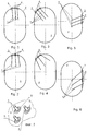
Fig. 1 shows a schematic of electrodes arrangement on the basis located on the inner case side with electrodes slightly deviating from the longitudinal symmetric axis of the case irregularly spaced on the basis and arranged inside the case according toEmbodiment 1. -
Fig. 2 provides a schematic of electrodes arrangement on the basis located on the inner case side with electrodes slightly deviating from the longitudinal symmetric axis of the case and irregularly spaced on the basis, electrode longitudinal axes deviating from each other at small angles. -
Figs. 3 and 4 represent a schematic drawing of lateral entry of electrodes arranged downwards according toEmbodiment 1, with relative orientation of electrode longitudinal axes similar toFigs 1 and 2 respectively. The electrode basis is arranged on the outer side of the case. -
Figs. 5 and 6 provide a schematic of a view of lateral entry of electrodes with their free ends arranged downwards according toEmbodiment 1, with relative orientation of electrode longitudinal axes similar toFigs 1 and 2 respectively, with an in-case arrangement of electrode basis. -
Fig. 7 shows a section of boiler case with an external view on outer electrode terminals with electrodes fastening in case the basis is implemented of metal. -
Figs. 8...13 show a schematic of electrodes arrangement on the basis similar toFigs. 1...7 with electrodes arranged inside the case upwards according toEmbodiment 2. -
Fig. 14 represents a side view of a multiple electrode with electrodes arranged on the basis in parallel. -
Fig. 15 shows a side view of a multiple electrode with electrodes arranged on the basis in parallel, irregularly and asymmetrically; fixing insulating washer being pressed-in at free electrode ends. -
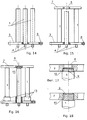
Fig. 16 gives a side view of a multiple electrode with electrodes arranged on the basis in parallel, irregularly and asymmetrically; dielectric bushings being fitted on electrodes at the points of their attaching to the basis and fixing insulating washer connected to free electrode ends by threaded connection. -
Figs. 17-18 illustrate sub-embodiments of electrode threaded connection to the fixing insulating washer with pockets formed and in flush. -
Fig. 19 gives a side view of a multiple electrode with dielectric bushings of different heights on electrodes and a sub-embodiment of electrode threaded connection to the fixing washer by means of nuts flushed in the fixing washer,Fig. 20 shows a view of the said connection. -
Figs. 21...23 represent top views of fixing washers of different shapes in plane. -
Figs. 24...25 give a side view of multiple electrode with dielectric bushings of equal height on electrodes in the first sub-embodiment and of reduced height in the second sub-embodiment; free electrode ends being pressed-in with pockets formed in the fixing washer. -
Figs. 26...27 give a side view of multiple electrode with dielectric bushings of different heights on electrodes, sunk into the groove around electrodes. -
Fig. 28 shows a view of electrode dielectric bushing connection to the basis; the joint being sealed. -
Fig. 29 represents a view of case part from outside on the side of electrode terminals according toEmbodiment 3. -
Figs. 30...36 illustrate sub-embodiments ofEmbodiment 3 of electrode arrangement without basis, directly inside the case; electrodes being arranged and oriented in various ways inside the case. -
Figs. 1...7 ,14 ...28 represent a view of configuration of electrode boiler with multiple electrode according toEmbodiment 1 of this invention. - As per
Embodiment 1,electrodes 1 of the device, at least one or more electrodes are directed inside thecase 2 downwards. InFig. 1 ,electrodes 1 are directed straight down, the longitudinal axes of all theelectrodes 1 slightly deviating from the longitudinal symmetric axis ofcase 2.Electrodes 1 if used more than one in number may be installed at different unequal distances to each other (Fig. 1 ). Longitudinal axes of part or of allelectrodes 2 may also form nonzero angles against each other as shown inFig. 2 accompanied by unequal distances betweenelectrodes 1.Electrodes 1 are located atbasis 3 which may be installed both insidecase 2, as shown inFigs. 1-2, 5-6 , and outside -Figs. 3-4 . Eachelectrode 1 hasterminal 4 running throughbasis 3 andcase 2 to be connected to an electric power supply.Basis 3 may be implemented of electrically insulating heat-resistant material or of metal. In thelast case electrodes 1 shall be installed on the basis thorough electricallyinsulating inserts 5 as shown inFig. 7 . The downward direction ofelectrodes 1 makes it possible to prevent entirely sludge deposition onbasis 3 or section ofcase 2 betweenelectrodes 1. This allows a considerable reduction of the probability of a breakdown betweenelectrodes 1 along the surface ofbasis 3 or those of parts ofcase 2 betweenelectrodes 1.Case 2 may be implemented either as fully enclosed split / with an opening cover as well as with drain tubes or as flowing, subject to the specific embodiment of the device. -
Figs. 3-4 show an arrangement of electrodes with large angles of deviation from the longitudinal symmetry axis, i.e., entry ofelectrodes 1 downwards at the side ofboiler case 2, this also accompanied by an irregular asymmetric arrangement of electrodes against each other, i.e., by different distances between the points of their entry tocase 2 and different angles between longitudinal axes ofelectrodes 3,Fig. 4 . -
Figs. 5-6 illustrate the arrangement ofelectrodes 1 on the side face ofcase 2, their longitudinal axes deviating from the symmetric axes of the case and from each other (Fig. 6 ) with the direction of electrode ends into the lower part ofcase 2. In this case as well as in other sub-embodiments,basis 3 may be fixed both insidecase 2 and outside it. -
Fig. 14 representsmultiple electrode 1, fastened by pressing into electrical insulatingbasis 3 with open free ends ofelectrodes 1 to be installed insidecase 2 or from outside into case according toFigs. 1-13 .Basis 3 hasholes 6 to attach it tocase 2. The multiple electrode may have fixingwasher 7,Fig. 15 , located at the ends ofelectrodes 1 to lock their initial position against displacement and distortions in dynamic conditions of heating/cooling. Here,electrodes 1 are pressed into fixingwasher 7 implemented of electrical insulating heat-resistant material having its coefficient of expansion equal or close to the coefficient of expansion ofbasis 3.Electrodes 1 are pressed intoholes 8 ofwasher 7 by its full thickness (Fig. 15 ) or its partial thickness (Figs. 16-17 ,19-20 ) with pockets being formed. The position ofelectrodes 1 onbasis 3 and thus on washer is asymmetric (Figs. 15-16 ,19-20, 22 ). Thereat such a fastening of fixingwasher 7 allows maintaining of position ofelectrodes 1 according toFigs. 1-12 in any operation modes of the device preventing any changes in the current propagation paths, possibility of short-circuit between electrodes, shorting across electrodes, and in its turn improves the efficiency and stability of device operation. -
Figs. 16-18 illustrate a sub-embodiment of fastenning ofelectrodes 1 in fixingwasher 7 by means ofthread 9 cut on the outer surface ofchamfers 10 of the end ofelectrode 1 of round cross-section. In thiscase electrodes 1 are screwed with their ends intowasher 7 by partial thickness ofwasher 7 with pockets being formed -Fig. 17 , or by its full thickness -Fig. 18 . It is assumed thatwasher 7 hasholes 8 provided with a thread corresponding tothread 9 onchamfers 10 ofelectrodes 1. This allows an extension of the device variety and increase of its adaptability to actual manufacturing methods. Besides, under certain circumstances this can facilitate device assembly, especially if the noncriticality of electrode screwing by the full thickness of the fixing washer is introduced into the invention. -
Figs. 19-23 show sub-embodiments of fastening ofwasher 7 at the ends ofelectrodes 1 by means ofnuts 11 to be installed inpockets 12 ofwasher 7. In this case chamfers 10 of free ends ofelectrodes 1 are implemented of round cross-section and of diameter allowing their easy coming intowasher holes 8 implemented as threadless. Afterwasher 7 is installed at the ends ofelectrodes 1,nuts 11 are screwed until tight into the bottom of pockets ofwasher 7, this resulting innuts 11 not protruding from the surface ofwasher 7.Washer 7 in plane may have the shape of a circle, ellipse, polygon, star, etc. (Figs. 21-23 ). -
Figs. 24-28 represent sub-embodiments of a device comprising all the above named attributes as related to the electrode arrangement and implementation as claimed in the above embodiments in various combinations, which additionally comprisebushings 13 implemented of electrical insulating heat-resistant material.Bushings 13 are made as cylindrical segments which internal cross-section in its shape replicates approximately or accurately the cross-section ofelectrodes 1.Bushings 13 are superposed onelectrodes 1 so that one butt of eachbushing 13 rests against basis 3 -Figs. 19 ,24, 25 . - The height of
bushings 13 in sub-embodiments ofEmbodiment 1 may be equal for all electrodes 1 (Figs. 24, 25 ) or different (Figs. 19 ,26 ). The boiler capacity can be controlled over a wide range by a simultaneous increase or reduction in the height ofbushings 13, without any changes made to the design, number, and arrangement of electrodes. Changing the height ofbushings 13 atvarious electrodes 1 individually and independently, as shown inFigs. 19 ,27 , one can control not only the total capacity but loading for each phase as well in the case of multiple (three-) phasing - In the case of sub-embodiments (
Figs. 19 ,26-28 ) of the device withinEmbodiment 1,bushings 13 may be installed directly onbasis 3 and secured, for instance, withsealant 14. They also may be installed incircular groove 15 onbasis 3 aroundelectrodes 1 implemented to the cross-sectional shape ofbushing 13 and secured withseal 14 as well,Fig. 28 . In addition,bushings 13, especially as secured withsealant 14, allow a reduction or even prevention of the probability of a breakdown betweenelectrodes 1, along the surface ofbasis 3 including after a period of operation in the case of gradual deposition of foreign particles, sludge on it. -
Figs. 8-28 represent a view of electrode boiler with multiple electrode configuration according toEmbodiment 2 of the invention in question.Embodiment 2 has the following specific aspects as compared toEmbodiment 1. - As per
Embodiment 2,electrodes 1 of the device, at least one electrode or more, for example two or three for a three-phase electric mains, or in number multiple of 3 for a three-phase electric mains - are directed intocase 2 upwards. InFig. 8 electrodes 1 are directed upwards vertically with the longitudinal axes of allelectrodes 1 slightly deviating from the longitudinal symmetric axis ofcase 2.Electrodes 1, if used in number exceeding one, may be installed at different unequal distances from each other (Fig. 8 ). The longitudinal axes of electrodes may also make non-zero angles against each other for allelectrodes 2 or a part of them as shown inFig. 9 ; this being accompanied with unequal distances betweenelectrodes 1 at the same time.Electrodes 1 are located onbasis 3 which similarly toEmbodiment 1 may be installed either insidecase 2,Figs. 10-11 , or outside it -Figs. 8-9, 12-13 . -
Figs. 10-11 show the electrode arrangement with large angles of deviation from the longitudinal symmetric axis, notably the entry ofelectrodes 1 upwards at the side ofboiler case 2, this accompanied with an irregular asymmetric arrangement of electrodes with respect to each other, i.e., with different distances between their points of entry tocase 2 and different angles between the longitudinal axes ofelectrodes 3,Fig. 11 . -
Figs. 12-13 illustrate the arrangement ofelectrodes 1 on the side surface ofcase 2, their longitudinal axes deviating from the case symmetric axes and from each other (Fig. 13 ), and electrode ends being directed into the upper part ofcase 2. In this case as well as in othersub-embodiments basis 3 may be secured either insidecase 2 or outside it. - Such an implementation of electrode arrangement allows considering of specific design features of some boiler types, simplifying their manufacturing processes, routine maintenance, and repairs. Besides, this provides opportunities of boiler convection improvement and enhancement of its efficiency in static operation conditions.
- Specific aspects of concrete embodiment of
electrode 1 or a multiple electrode comprisingseveral electrodes 1 coincide withEmbodiment 1 as shown inFigs 14-28 . -
Figs. 29-36 represent a view of configuration of an electrode boiler with multiple electrode according toEmbodiment 3 of this invention.Embodiment 3 has the following specific aspects as compared toEmbodiments - As per
Embodiment 2,electrodes 1 of the device, at least one electrode or more, for example two or three for a three-phase electric mains, or in number multiple of 3 for a three-phase electric mains, or in any required number, generally all used in a concrete specimen of the device, are fastened directly incase 2 without any basis. Such an implementation of the device provides (Fig. 29 ) fastening ofelectrodes 1 through dielectric insulating heat-resistant inserts 5 directly pressed into the wall ofcase 2 or its cover. Here,terminals 4 ofelectrodes 1 for connection of an electric power supply are brought outside from thedevice case 2. -
Electrodes 1 may be grouped at the same point of boiler case similarly toEmbodiments case 2 as required to meet the specific problem of the device. The implementation of electrodes fastening incase 2 as claimed by this Embodiment, directly without intermediate basis, allows not to bindelectrodes 1 into a multiple electrode, this technologically simplifying the distribution of their fastening over the case surface and thus over the internal space of the boiler. This expands the functionality and assortment range of the device embodiments, enhances its versatility, and increases the range of concrete tasks to be met. - In the Embodiment in question,
Figs. 30-36 , any combinations of arrangement of any number ofelectrodes 1 are possible, with electrodes deviating from the boiler symmetric axes and from the strict regularity of their location to a variable degree, with any slope angles with respect to each other. The possibility of such an asymmetry in the arrangement ofelectrodes 1 and its variation is not found to be mentioned in any literary sources and considerably simplifies the fabrication technique and repair of the device and reduces their cost; it also bates the safety requirements in maintenance of the device, in particular as to its cleaning and desludging. The ample opportunities of the variety of asymmetric fastening ofelectrodes 1 allow a better selection of their optimum arrangement and organization to the best advantage of boiler convection process subject to the case configuration, specific designation, and design of the boiler. This also enables planning and controlling the asymmetry in the processes of sludge deposition on components of the electrode system allowing introducing a non-uniformity into the decrease of boiler efficient operation within intervals between scheduled cleanings, this making it possible to increase its efficiency. - The operation of boiler in all its embodiments is as follows.
- The boiler can be used as self-contained or its
case 2 is built-in into an open or circulating water heating system at any required point. The heating system is filled with water treated in usual manner with its resistance brought, andelectrodes 1 of boiler are connected by means ofterminals 4 arranged outside itscase 2 to an external single-phase or three-phase electrical circuit. Cooled water from heating radiators is supplied intoboiler case 2 where it is heated by electric current passing through it betweenelectrodes 1. The heated water fromcase 2 is supplied to consumers, heating radiators, for example. Convection processes occurring inboiler case 2 during water heating betweenelectrodes 1 can be purposefully organized by the mutual orientation and arrangement of electrodes so that the boiler can be operated as a circulating pump without any forced water pumping in the closed system. This is considerably contributed by the provided in present invention manner of mutual orientation, possibility of an asymmetric arrangement of electrodes inside the case and relative to each other. In addition, this allows a redistribution of sludge formation processes inclusive of those at electrodes themselves. The electrode arrangement as provided by this invention makes it possible to select the current passage paths and vary the current-density distribution thus enabling an optimization of boiler operation both in static and dynamic conditions.
Claims (28)
- Electrode boiler with electrodes unit comprising:a) a case (2); andb) multiple electrodes in the form of fastened inside the case rod electrodes (1); wherein the electrodes have longitudinal axes not coinciding with the case longitudinal axis; wherein the electrodes longitudinal axes do not coincide with the case transverse axis; wherein the electrodes have external terminals brought out from the case outside;characterized in that the electrodes (1) are arranged non-symmetrically relative to the case symmetry axes and to each other.
- Electrode boiler with electrodes unit according to claim 1, the multiple electrodes also comprise at least one electrode basis (3).
- Electrode boiler with electrodes unit according to claim 2, wherein the electrode boiler basis (3) is implemented in the form of a plate,a) electrodes being fastened to the plate, and electrodes (1) are fixed on one side of its first surface so that their longitudinal axes are arranged in the direction close to the normal one with respect to the first plate surface;b) electrode basis (3) being fastened with the second surface on the inner side of the case (2).
- Electrode boiler with electrodes unit according to claim 2, wherein the basis is implemented of electrically insulating heat-resistant material.
- Electrode boiler with electrodes unit according to claim 2, wherein the electrode basis (3) is implemented of metal.
- Electrode boiler with electrodes unit according to claim 3, wherein the electrode basis (3) is fastened with the second plane on the inner case side so that electrode ends are directed inside the internal boiler space.
- Electrode boiler with electrodes unit according to claim 6, wherein the electrode basis (3) is fastened with the second plane on the inner side of the upper half-case so that electrode ends are directed inside the internal boiler space downwards.
- Electrode boiler with electrodes unit according to claim 6, wherein the electrode basis (3) is fastened with the second plane on the inner side of the upper half-case so that free electrode ends are directed inside the internal boiler space laterally.
- Electrode boiler with electrodes unit according to claim 6, wherein the electrode basis (3) is fastened with its second plane on the inner side of the lower half-case so that free electrode ends are directed inside the internal boiler space upwards.
- Electrode boiler with electrodes unit according to claim 3, wherein the electrode basis (3) is fastened with one its plane on the outer case side so that electrode ends are directed inside the internal boiler space.
- Electrode boiler with electrodes unit according to claim 10, wherein the electrode basis (3) is fastened with the first plane on the outer side of the upper half-case so that electrode ends are directed inside the internal boiler space downwards.
- Electrode boiler with electrodes unit according to claim 10, wherein the electrode basis (3) is fastened with the first plane on the outer side of the upper half-case so that free electrode ends are directed inside the internal boiler space laterally.
- Electrode boiler with electrodes unit according to claim 10, wherein the electrode basis (3) is fastened with its first plane on the outer side of the lower half-case so that free electrode ends are directed inside the internal boiler space upwards.
- Electrode boiler with electrodes unit according to claim 3:a) the electrode boiler comprising insulating bushings (13) implemented in the form of cylindrical tubes, superposed on the first electrode ends and connected to the basis until they rest in the basis;b) the bushings (13) being constructively sunk, at least partially, in the basis; whereinc) the height of bushings (13) may vary.
- Electrode boiler with electrodes unit according to claim 14, wherein the height of bushings may vary equally for all the electrodes.
- Electrode boiler with electrodes unit according to claim 14, wherein the height of bushings may vary individually for each electrode.
- Electrode boiler with electrodes unit according to claim 14, wherein silicon joint sealant (14) is applied between the basis and bushings (13) at the interfaces.
- Electrode boiler with electrodes unit according to claim 14, wherein:a) in the electrode boiler with multiple electrodes the boiler case (2) is used as the electrode basis (3) as well;b) bushings (13) being inserted into through holes of the case so that they seal and insulate the case from the electrodes;c) electrode ends are brought through the bushings (13) outside from the case, bushings being electric terminals.
- Electrode boiler with electrodes unit according to claim 18, wherein besides, in the electrode boiler with multiple electrodes free electrode ends are directed inside the boiler.
- Electrode boiler with electrodes unit according to claim 2, comprising the electrode boiler with multiple electrodes also comprises a fixing element implemented in the form of at least one washer (7) having holes (8) through which free electrode ends are brought.
- Electrode boiler with electrodes unit according to claim 20, wherein electrodes are pressed in the fixing element at least by a partial depth of the fixing element.
- Electrode boiler with electrodes unit according to claim 20, comprises the following:a) chamfers (10) made on the second electrode ends, which diameter corresponds to the diameter of washer holes (8);b) screw thread (9) on the chamfers (10) of second electrode ends; electrodes (1) being screwed with their threaded parts into the washer holes (8), at least by the third part of washer thickness;c) nuts (11) being fitted on the threaded electrode parts after the washer (7) on the side of second electrode ends; and the washer (7) resting against electrode shoulders formed by the chamfers (10) and being tightly pressed by nuts (11).
- Electrode boiler with electrodes unit according to claim 21, comprising the electrode boiler with multiple electrodes also comprises the following: pockets (12) made on washer surfaces, their centre coinciding with the hole centres.
- Electrode boiler with electrodes unit according to claim 23, whereina) the pocket depth corresponds to the nut height; and the nuts (11) screwed on electrode ends being arranged in the pockets (12) in flush.
- Electrode boiler with electrodes unit according to claim 22, wherein the nuts (11) are made of electric insulating material.
- Electrode boiler with electrodes unit according to claim 22, wherein the nuts (11) are made of heat-resistant material.
- Electrode boiler with electrodes unit according to claim 22, wherein the nuts (11) are made of metal.
- Electrode boiler with electrodes unit according to claim 22, wherein:a) there is also an electrode boiler with multiple electrodes in which: expansion coefficient of washer material corresponds to the expansion coefficient of basis material;b) expansion coefficient of nut material corresponds to the expansion coefficient of washer material.
Applications Claiming Priority (1)
| Application Number | Priority Date | Filing Date | Title |
|---|---|---|---|
| PCT/IB2012/003083 WO2014087190A1 (en) | 2012-12-05 | 2012-12-05 | Electrode boiler with electrodes unit |
Publications (3)
| Publication Number | Publication Date |
|---|---|
| EP2929242A1 EP2929242A1 (en) | 2015-10-14 |
| EP2929242A4 EP2929242A4 (en) | 2016-07-20 |
| EP2929242B1 true EP2929242B1 (en) | 2018-10-24 |
Family
ID=50882853
Family Applications (1)
| Application Number | Title | Priority Date | Filing Date |
|---|---|---|---|
| EP12889526.5A Active EP2929242B1 (en) | 2012-12-05 | 2012-12-05 | Electrode boiler with electrodes unit |
Country Status (9)
| Country | Link |
|---|---|
| US (1) | US9841183B2 (en) |
| EP (1) | EP2929242B1 (en) |
| JP (1) | JP6298825B2 (en) |
| KR (1) | KR101560373B1 (en) |
| CN (1) | CN104822988B (en) |
| CA (1) | CA2894137C (en) |
| IN (1) | IN2015DN02628A (en) |
| RU (1) | RU2014128960A (en) |
| WO (1) | WO2014087190A1 (en) |
Families Citing this family (15)
| Publication number | Priority date | Publication date | Assignee | Title |
|---|---|---|---|---|
| US20140227649A1 (en) * | 2013-02-12 | 2014-08-14 | Clearsign Combustion Corporation | Method and apparatus for delivering a high voltage to a flame-coupled electrode |
| CA2942371A1 (en) * | 2014-03-24 | 2015-10-01 | Ohio University | Fluid processing system with a heating element and related method |
| CN105890152B (en) * | 2016-06-03 | 2018-10-02 | 北京瑞特爱能源科技股份有限公司 | A kind of liquid level PCU Power Conditioning Unit for high-power grill pan stove heat electrode |
| WO2018015780A1 (en) * | 2016-07-20 | 2018-01-25 | KIM, No Eul | Multi-phase hot boiler |
| WO2020231386A1 (en) * | 2019-05-10 | 2020-11-19 | Heatworks Technologies, Inc. | Devices for ohmically heating a fluid |
| AU2017355627B2 (en) * | 2016-11-07 | 2021-11-11 | OhmIQ, Inc. | Devices for ohmically heating a fluid |
| CN106413166A (en) * | 2016-11-29 | 2017-02-15 | 李宝柱 | Electric heater |
| US20180135883A1 (en) * | 2017-07-11 | 2018-05-17 | Kenneth Stephen Bailey | Advanced water heater utilizing arc-flashpoint technology |
| CN107655210A (en) * | 2017-08-31 | 2018-02-02 | 浙江特富锅炉有限公司 | Phase-change type steam generator system |
| CN108295776B (en) * | 2018-04-27 | 2020-03-27 | 中国科学院上海应用物理研究所 | Solid salt heating and melting device and method |
| KR101977601B1 (en) * | 2018-11-12 | 2019-05-10 | 갈란보일러 주식회사 | Electric-ion boiler and control method thereof |
| FI4153910T3 (en) * | 2020-05-22 | 2024-02-22 | Parat Halvorsen As | An electrode boiler |
| CN114992616A (en) * | 2022-07-07 | 2022-09-02 | 山东北辰机电设备股份有限公司 | A spiral plate type low pressure electrode steam generator |
| WO2025043324A1 (en) * | 2023-08-31 | 2025-03-06 | Acceleware Ltd. | Systems and methods for heating a conductive feedstock |
| CN119687438B (en) * | 2025-02-25 | 2025-04-15 | 上海方快锅炉有限公司 | Electrode steam boiler with adjustable load |
Family Cites Families (103)
| Publication number | Priority date | Publication date | Assignee | Title |
|---|---|---|---|---|
| US1475645A (en) * | 1923-11-27 | Otto meyer-keller | ||
| US1548741A (en) * | 1925-08-04 | Electric liquid hbatins system | ||
| US421499A (en) * | 1890-02-18 | Art of heating water and generating steam by electricity | ||
| US1527707A (en) * | 1921-09-03 | 1925-02-24 | Gen Electric | Electrically-heated liquid heater |
| US1503972A (en) * | 1922-09-13 | 1924-08-05 | Gen Electric | Electric boiler |
| US1522188A (en) * | 1923-11-21 | 1925-01-06 | Gen Electric | Electric heating device and method |
| FR784573A (en) | 1934-02-10 | 1935-07-22 | Zander & Ingestroem | Improvement of bar-shaped electrodes for electric heating of steam boilers or the like |
| US2050607A (en) * | 1934-02-10 | 1936-08-11 | Aktiabalaget Zander & Ingestro | Electrode for electrically heated steam boilers and the like |
| US2162462A (en) * | 1936-11-18 | 1939-06-13 | Elmer A Reid | Humidifier |
| US2263549A (en) * | 1938-08-05 | 1941-11-18 | Saint Gobain | Electrical heating of liquid baths |
| DE886503C (en) | 1941-10-25 | 1953-08-13 | Junker & Ruh A G | Electrode steam heater |
| US2387103A (en) * | 1943-05-07 | 1945-10-16 | Wicks Geraldo Cyro | Steam boiler |
| GB663286A (en) * | 1949-02-19 | 1951-12-19 | G W B Electric Furnaces Ltd | Electrode boilers |
| US3246276A (en) * | 1963-04-03 | 1966-04-12 | Gen Services Company | Liquid rheostat |
| NL302880A (en) * | 1963-04-30 | |||
| US3242313A (en) * | 1963-08-27 | 1966-03-22 | Wilbur N Lamphier | Electrode type vapor generator |
| CH405524A (en) | 1963-09-16 | 1966-01-15 | Emilius Wilson Ernest | Electric steam generator |
| US3520979A (en) * | 1968-02-26 | 1970-07-21 | Penelectro Ltd | Electrode circuit for hex electric furnace |
| SU379995A1 (en) | 1969-08-14 | 1973-04-20 | ||
| ZA71146B (en) * | 1970-01-27 | 1971-10-27 | S Williams | Improvements in and relating to electrode boilers |
| DE2127075A1 (en) * | 1970-06-04 | 1971-12-16 | Dall H | Electrode humidifier with a constant amount of steam emitted |
| JPS525102B2 (en) * | 1971-08-16 | 1977-02-09 | ||
| SU465521A1 (en) | 1972-12-11 | 1975-03-30 | Карагандинский политехнический институт | Electric steam generator |
| US3931530A (en) | 1973-07-19 | 1976-01-06 | National Research Development Corporation | Apparatus for controlling the supply of power to a resistive load |
| SE380609B (en) | 1974-04-05 | 1975-11-10 | Goteborgs Analyslaboratorium A | WAY TO ELIMINATE COATINGS ON WORKING ELECTRODES AND DEVICES FOR PERFORMING THE KIT BY ELECTRODAN DISTRIBUTORS |
| DE2456665B2 (en) | 1974-11-30 | 1979-05-17 | Gebrueder Sulzer Ag, Winterthur (Schweiz) | Electrode for water jet electrode steam generator |
| US4169558A (en) * | 1976-09-01 | 1979-10-02 | CAM Industries Inc. | Water distribution chamber for an electric steam generator |
| CH612491A5 (en) | 1976-09-23 | 1979-07-31 | Sulzer Ag | |
| DE2732683A1 (en) | 1977-07-20 | 1979-02-01 | Normbau Gmbh | Steam generator with immersion electrode for three=phase supply - has screw control rod to adjust current from outside by varying electrode to liq. contact area |
| SU879184A1 (en) | 1980-01-30 | 1981-11-07 | Предприятие П/Я А-7114 | Air preheater |
| US4423310A (en) * | 1981-04-06 | 1983-12-27 | Wehr Corporation | Electrical steam generator having adjustable electrodes for an air humidifier |
| US4394561A (en) * | 1981-04-06 | 1983-07-19 | Wehr Corporation | Tank structure for an air humidifying electrode steam generator |
| NO813278L (en) | 1981-09-28 | 1983-03-29 | Sigurd Heien | BOILER. |
| US4435811A (en) | 1982-01-26 | 1984-03-06 | Owens-Corning Fiberglas Corporation | Current distribution for glass-melting furnaces |
| SU1064083A1 (en) | 1982-05-19 | 1983-12-30 | Предприятие П/Я А-7114 | Electrode-type heater |
| CA1166296A (en) | 1982-11-18 | 1984-04-24 | Monique Howard-Leicester | Humidifier electrode shield |
| SU1174683A1 (en) | 1983-07-27 | 1985-08-23 | Pavel Z Sheremet | Electric heater of liquid |
| CH662637A5 (en) | 1983-08-11 | 1987-10-15 | Sulzer Ag | ELECTRIC STEAM GENERATOR. |
| CH665466A5 (en) | 1983-11-17 | 1988-05-13 | Sulzer Ag | ELECTRIC STEAM GENERATOR. |
| JPS61134503A (en) | 1984-12-01 | 1986-06-21 | 三浦工業株式会社 | Electric type once-through boiler |
| AU594323B2 (en) | 1985-02-28 | 1990-03-08 | Vapor Corporation | Electrode configuration for a high voltage electric boiler |
| SU1250791A1 (en) | 1985-03-14 | 1986-08-15 | Предприятие П/Я А-7114 | Electrode heater |
| DE3521102A1 (en) | 1985-06-12 | 1986-12-18 | Zdravko 7990 Friedrichshafen Mladenović | METHOD AND DEVICE FOR CONVERTING ELECTRICAL ENERGY INTO HEATING ENERGY |
| SU1333992A1 (en) | 1985-08-01 | 1987-08-30 | Ленинградский сельскохозяйственный институт | Electrode heater |
| GB2178834B (en) | 1985-08-05 | 1988-10-05 | James Eric Entwistle | Steam generator |
| FR2587449B1 (en) | 1985-09-18 | 1989-11-03 | Electricite De France | DIRECT HEATING BOILER FOR THE PRODUCTION OF STEAM AND / OR HOT WATER |
| AU5046285A (en) | 1985-11-29 | 1987-06-04 | Chang, T-S. | Device for fast generation of steam vapour |
| FR2593890B1 (en) | 1986-01-24 | 1989-01-06 | Caliqua | ELECTRIC STEAM GENERATOR WITH IMPROVED WATER JETS |
| FR2595052B1 (en) | 1986-03-03 | 1990-06-01 | Armines | METHOD AND DEVICE FOR RAPID VAPORIZATION OF A LIQUID |
| FI862213A7 (en) | 1986-05-26 | 1987-11-27 | Oy Santasalo Sohlberg Ab | Electrically heated steam generator and its use in a distillation apparatus. |
| CH670147A5 (en) | 1986-06-18 | 1989-05-12 | Sulzer Ag | |
| SE459762B (en) | 1986-06-24 | 1989-07-31 | Tecator Ab | AN ELECTRICALLY HEATED STEAM GENERATOR WITH A CONTAINER CONTAINING TWO COMMUNICATING CHAMBERS, WHERE ONE Chamber HAS THE HEATING ELEMENT AND THE OTHER A LEVEL DETECTOR |
| GB8806486D0 (en) * | 1988-03-18 | 1988-04-20 | Eaton Williams Raymond H | Humidifier control means |
| SU1638444A1 (en) | 1989-04-04 | 1991-03-30 | Орловский научно-исследовательский институт легкого машиностроения | Steam generator |
| JPH0354590A (en) | 1989-04-18 | 1991-03-08 | Sanyo Electric Co Ltd | Route search method |
| GB8909510D0 (en) | 1989-04-29 | 1989-06-14 | Earlex Ltd | Steam generator |
| JPH0363872A (en) | 1989-08-02 | 1991-03-19 | Omron Corp | Latency time output fuzzy controller for automatic transaction machine |
| JP2971980B2 (en) * | 1991-04-24 | 1999-11-08 | 亮拿 佐藤 | Power plant |
| DK170757B1 (en) | 1992-03-05 | 1996-01-15 | Wittenborg As | Water container for heating water preferably in a beverage dispenser |
| RU2037088C1 (en) | 1992-06-30 | 1995-06-09 | Конструкторское бюро химавтоматики | Three-phase electric water heater |
| DE4328718A1 (en) | 1993-08-26 | 1995-03-02 | Abb Gadelius K K | Heating element |
| CH686976A5 (en) * | 1993-03-23 | 1996-08-15 | Condair Ag | Evaporation device for an electric steamer Denver. |
| CN1082683A (en) | 1993-06-22 | 1994-02-23 | 鲁正祥 | A kind of method of efficient generation steam and seven kinds of high-efficiency steam heating power type electrical equipment |
| US5454059A (en) | 1993-10-18 | 1995-09-26 | Regehr; Martin W. | Evaporation control adaptor sleeve for vaporizer electrode |
| US5384888A (en) | 1993-12-13 | 1995-01-24 | Duracraft Corporation | Vaporizer with electrode positioning |
| DE59503331D1 (en) | 1994-12-01 | 1998-10-01 | Muenster Ag | Method for preventing incrustations from forming in a water container, and water container with a device for carrying out this method |
| IT1278873B1 (en) | 1995-12-07 | 1997-11-28 | Giuliano Franchini | QUICK STEAM PRODUCTION BOILER |
| EP0857914A3 (en) | 1997-02-05 | 1999-06-23 | Denel (Proprietary) Limited, Eloptro Division | Steam generator |
| AU5776898A (en) | 1997-02-14 | 1998-09-08 | Ecovap Sa | Steam generator |
| CN2306395Y (en) | 1997-06-11 | 1999-02-03 | 钲德电热股份有限公司 | Electrode Steam Generator |
| US5940578A (en) | 1997-06-17 | 1999-08-17 | Yen Enterprises Pty Ltd. | Water evaporation apparatus |
| IT1295505B1 (en) | 1997-09-30 | 1999-05-12 | Vapor Service Srl | MAKE-UP PROCEDURE FOR BOILERS IN STEAM GENERATION MACHINES |
| RU2137029C1 (en) | 1997-12-26 | 1999-09-10 | Ильин Андрей Павлович | Hot-water electrode boiler |
| US6263156B1 (en) * | 1998-03-31 | 2001-07-17 | Denis-Michel Ledoux | Recycling of air humidifier cylinders |
| US6130990A (en) | 1998-08-25 | 2000-10-10 | Nestec S.A. | On-demand direct electrical resistance heating system and method thereof |
| IT246360Y1 (en) | 1998-11-25 | 2002-04-08 | Andrea Gerosa | DEVICE TO CREATE STEAM INSTANTLY |
| RU12637U1 (en) | 1999-08-04 | 2000-01-20 | Ильин Андрей Павлович | ELECTRODE LIQUID HEATER |
| RU2168875C1 (en) | 1999-12-28 | 2001-06-10 | Ильин Андрей Павлович | Electrode for electrode-type liquid heater |
| RU2168876C1 (en) | 1999-12-28 | 2001-06-10 | Ильин Андрей Павлович | Electrode for electrode-type water boiler |
| DE10000101B4 (en) * | 2000-01-04 | 2005-06-02 | Robin Gollinger | Device for heating liquids |
| KR20010084150A (en) | 2000-02-24 | 2001-09-06 | 조중휴 | Electric boiler |
| RU16419U1 (en) | 2000-02-29 | 2000-12-27 | Ильин Андрей Павлович | ELECTRODE LIQUID HEATER AND ELECTRODE (OPTIONS) |
| EP1269072B1 (en) | 2000-03-30 | 2006-07-12 | IMETEC S.p.A. | Household steam generator apparatus |
| RU2189541C2 (en) | 2000-04-11 | 2002-09-20 | Ильин Андрей Павлович | Electrode type liquid heater |
| KR20020013018A (en) | 2000-08-10 | 2002-02-20 | 이상갑 | A control method and apparatus of an electric steam boiler |
| JP2002317902A (en) | 2001-04-19 | 2002-10-31 | Toray Eng Co Ltd | Nozzle assembly for electrode type electric boiler |
| RU2225569C2 (en) | 2001-08-30 | 2004-03-10 | Открытое акционерное общество "Сибэнергомаш" | Steam generator |
| RU2209367C1 (en) | 2001-11-22 | 2003-07-27 | Дальневосточный государственный технический университет | Electric boiler |
| JP2003338356A (en) * | 2002-05-20 | 2003-11-28 | Sumitomo Osaka Cement Co Ltd | Mounting structure of heating element and metallic electrode |
| KR20030090894A (en) | 2002-05-22 | 2003-12-01 | 이평희 | vapor generator of simple type |
| RU43624U1 (en) | 2004-10-06 | 2005-01-27 | Бергер Елена Андреевна | ELECTRODE BLOCK FOR ELECTRODE BOILER |
| KR100733304B1 (en) | 2005-02-21 | 2007-06-28 | 엘지전자 주식회사 | Water heating device using electrodes |
| WO2006097002A2 (en) | 2005-03-14 | 2006-09-21 | Axair Ag | Steam generator comprising a swirling device |
| DE102006047042A1 (en) | 2006-10-02 | 2008-04-03 | Emitec Gesellschaft Für Emissionstechnologie Mbh | Device for evaporating reducing agent e.g reducing agent precursor solution and reducing agent solution, has electrically heated warming zone, which has electrically operated heating element with heating resistor |
| GB0624028D0 (en) | 2006-11-30 | 2007-01-10 | Glover Dennis A | The "K" energy sydrome now researched more inner, operational uses known now as the "K" energy |
| RU2324859C1 (en) | 2006-12-04 | 2008-05-20 | Государственное образовательное учреждение высшего профессионального образования Томский политехнический университет | Electric steam generator |
| CN201145263Y (en) | 2007-12-13 | 2008-11-05 | 李振刚 | Electrical heating device of water |
| CA2712301C (en) | 2008-02-11 | 2016-08-16 | Microheat Technologies Pty Ltd | Segmented rapid heating of fluid |
| NO331435B1 (en) | 2009-02-20 | 2011-12-27 | Parat Halvorsen As | Electric boilers |
| KR20110135172A (en) | 2010-06-10 | 2011-12-16 | (주)에이치엠테크노 | Current controlled electric electrode boiler |
| CN202188476U (en) * | 2011-06-02 | 2012-04-11 | 苏州市新波能电热水炉有限公司 | Electrode boiler |
| KR101132125B1 (en) | 2012-01-17 | 2012-04-05 | (주)영화에너지 | A reactor using electrode catalyst for high efficiency steam generator |
| US9657965B2 (en) * | 2015-03-06 | 2017-05-23 | Stiebel Eltron Gmbh & Co. Kg | Water heater and method of controlling a water heater |
-
2012
- 2012-12-05 CN CN201280077451.4A patent/CN104822988B/en active Active
- 2012-12-05 KR KR1020157007478A patent/KR101560373B1/en not_active Expired - Fee Related
- 2012-12-05 EP EP12889526.5A patent/EP2929242B1/en active Active
- 2012-12-05 WO PCT/IB2012/003083 patent/WO2014087190A1/en not_active Ceased
- 2012-12-05 US US14/650,213 patent/US9841183B2/en active Active
- 2012-12-05 JP JP2015546098A patent/JP6298825B2/en active Active
- 2012-12-05 RU RU2014128960A patent/RU2014128960A/en unknown
- 2012-12-05 CA CA2894137A patent/CA2894137C/en active Active
-
2015
- 2015-03-31 IN IN2628DEN2015 patent/IN2015DN02628A/en unknown
Non-Patent Citations (1)
| Title |
|---|
| None * |
Also Published As
| Publication number | Publication date |
|---|---|
| US9841183B2 (en) | 2017-12-12 |
| EP2929242A1 (en) | 2015-10-14 |
| RU2014128960A (en) | 2017-01-13 |
| CA2894137A1 (en) | 2014-06-12 |
| CN104822988A (en) | 2015-08-05 |
| JP6298825B2 (en) | 2018-03-20 |
| IN2015DN02628A (en) | 2015-06-05 |
| KR101560373B1 (en) | 2015-10-15 |
| WO2014087190A1 (en) | 2014-06-12 |
| KR20150039892A (en) | 2015-04-13 |
| CA2894137C (en) | 2018-04-24 |
| CN104822988B (en) | 2016-10-26 |
| EP2929242A4 (en) | 2016-07-20 |
| HK1213622A1 (en) | 2016-07-08 |
| JP2016505797A (en) | 2016-02-25 |
| US20150316253A1 (en) | 2015-11-05 |
Similar Documents
| Publication | Publication Date | Title |
|---|---|---|
| US9841183B2 (en) | Electrode boiler with electrodes unit | |
| WO2018015780A1 (en) | Multi-phase hot boiler | |
| CN104806878A (en) | Water bath carburetor | |
| RU2684864C2 (en) | Capillary heater based on proximity effect with high degree of energy saving equipped higher along a flow with microfilter for removing lime particles present in fluid medium, and lower on flow with nozzle or closed contour | |
| US20200393202A1 (en) | A hot water storage tank and a diffuser | |
| KR20170103810A (en) | Horizontal steam generator for a reactor plant | |
| KR101418924B1 (en) | Induction Boiler | |
| HK1213622B (en) | Electrode boiler with electrodes unit | |
| EP3254033B1 (en) | Improvements in fluid storage systems | |
| US10406490B2 (en) | Flow control device for mitigating thermal stratification in mixing tee pipe | |
| KR102192008B1 (en) | Ion electrode boiler of open type | |
| CN204006617U (en) | A kind of Instant heating type hot-water heating system | |
| CN115930432B (en) | Electrode boiler and power calculation method | |
| CN202834736U (en) | Water cycle electric heating auxiliary vaporizer | |
| CA1230156A (en) | Electrical steam or vapour generator | |
| KR100872513B1 (en) | Jungle tube for reducing heat loss of pressurizer in integrated reactor | |
| KR101210832B1 (en) | apparatus for boiler of indirect heating type | |
| KR101008844B1 (en) | Hot water heater used for regenerative electric boiler with improved heat exchange and heat generation structure | |
| CN209890717U (en) | Galvanization plating assisting box | |
| KR102219962B1 (en) | Intermediate Induction Heating Type Boiler | |
| CN208418677U (en) | An intermediate header suitable for low-load flexible operation of supercritical boilers | |
| CN209399472U (en) | A kind of Multi-class propagation energy-saving electromagnetic heating system | |
| CN203861946U (en) | Glass lining distillatory boiler | |
| KR20060069370A (en) | Brown Gas Generator | |
| US20120145540A1 (en) | Electrolytic Cell for Heating Electrolyte by a Glow Plasma Field in the Electrolyte |
Legal Events
| Date | Code | Title | Description |
|---|---|---|---|
| PUAI | Public reference made under article 153(3) epc to a published international application that has entered the european phase |
Free format text: ORIGINAL CODE: 0009012 |
|
| 17P | Request for examination filed |
Effective date: 20150615 |
|
| AK | Designated contracting states |
Kind code of ref document: A1 Designated state(s): AL AT BE BG CH CY CZ DE DK EE ES FI FR GB GR HR HU IE IS IT LI LT LU LV MC MK MT NL NO PL PT RO RS SE SI SK SM TR |
|
| AX | Request for extension of the european patent |
Extension state: BA ME |
|
| DAX | Request for extension of the european patent (deleted) | ||
| RA4 | Supplementary search report drawn up and despatched (corrected) |
Effective date: 20160621 |
|
| RIC1 | Information provided on ipc code assigned before grant |
Ipc: H05B 3/02 20060101ALI20160615BHEP Ipc: H05B 3/60 20060101ALI20160615BHEP Ipc: F24H 1/20 20060101ALI20160615BHEP Ipc: F22B 1/30 20060101AFI20160615BHEP Ipc: F24H 1/10 20060101ALI20160615BHEP Ipc: H05B 3/03 20060101ALI20160615BHEP |
|
| 17Q | First examination report despatched |
Effective date: 20170524 |
|
| GRAP | Despatch of communication of intention to grant a patent |
Free format text: ORIGINAL CODE: EPIDOSNIGR1 |
|
| RIC1 | Information provided on ipc code assigned before grant |
Ipc: H05B 3/03 20060101ALI20180509BHEP Ipc: F24H 9/18 20060101ALI20180509BHEP Ipc: F24H 1/10 20060101ALI20180509BHEP Ipc: H05B 3/02 20060101ALI20180509BHEP Ipc: H05B 3/60 20060101ALI20180509BHEP Ipc: F22B 1/30 20060101AFI20180509BHEP Ipc: F24H 9/00 20060101ALI20180509BHEP Ipc: F24H 1/20 20060101ALI20180509BHEP |
|
| INTG | Intention to grant announced |
Effective date: 20180528 |
|
| GRAS | Grant fee paid |
Free format text: ORIGINAL CODE: EPIDOSNIGR3 |
|
| GRAA | (expected) grant |
Free format text: ORIGINAL CODE: 0009210 |
|
| AK | Designated contracting states |
Kind code of ref document: B1 Designated state(s): AL AT BE BG CH CY CZ DE DK EE ES FI FR GB GR HR HU IE IS IT LI LT LU LV MC MK MT NL NO PL PT RO RS SE SI SK SM TR |
|
| REG | Reference to a national code |
Ref country code: CH Ref legal event code: EP |
|
| REG | Reference to a national code |
Ref country code: IE Ref legal event code: FG4D |
|
| REG | Reference to a national code |
Ref country code: AT Ref legal event code: REF Ref document number: 1057113 Country of ref document: AT Kind code of ref document: T Effective date: 20181115 |
|
| REG | Reference to a national code |
Ref country code: DE Ref legal event code: R096 Ref document number: 602012052762 Country of ref document: DE |
|
| REG | Reference to a national code |
Ref country code: NL Ref legal event code: MP Effective date: 20181024 |
|
| REG | Reference to a national code |
Ref country code: LT Ref legal event code: MG4D |
|
| REG | Reference to a national code |
Ref country code: AT Ref legal event code: MK05 Ref document number: 1057113 Country of ref document: AT Kind code of ref document: T Effective date: 20181024 |
|
| PG25 | Lapsed in a contracting state [announced via postgrant information from national office to epo] |
Ref country code: NL Free format text: LAPSE BECAUSE OF FAILURE TO SUBMIT A TRANSLATION OF THE DESCRIPTION OR TO PAY THE FEE WITHIN THE PRESCRIBED TIME-LIMIT Effective date: 20181024 |
|
| PG25 | Lapsed in a contracting state [announced via postgrant information from national office to epo] |
Ref country code: LV Free format text: LAPSE BECAUSE OF FAILURE TO SUBMIT A TRANSLATION OF THE DESCRIPTION OR TO PAY THE FEE WITHIN THE PRESCRIBED TIME-LIMIT Effective date: 20181024 Ref country code: AT Free format text: LAPSE BECAUSE OF FAILURE TO SUBMIT A TRANSLATION OF THE DESCRIPTION OR TO PAY THE FEE WITHIN THE PRESCRIBED TIME-LIMIT Effective date: 20181024 Ref country code: FI Free format text: LAPSE BECAUSE OF FAILURE TO SUBMIT A TRANSLATION OF THE DESCRIPTION OR TO PAY THE FEE WITHIN THE PRESCRIBED TIME-LIMIT Effective date: 20181024 Ref country code: IS Free format text: LAPSE BECAUSE OF FAILURE TO SUBMIT A TRANSLATION OF THE DESCRIPTION OR TO PAY THE FEE WITHIN THE PRESCRIBED TIME-LIMIT Effective date: 20190224 Ref country code: PL Free format text: LAPSE BECAUSE OF FAILURE TO SUBMIT A TRANSLATION OF THE DESCRIPTION OR TO PAY THE FEE WITHIN THE PRESCRIBED TIME-LIMIT Effective date: 20181024 Ref country code: LT Free format text: LAPSE BECAUSE OF FAILURE TO SUBMIT A TRANSLATION OF THE DESCRIPTION OR TO PAY THE FEE WITHIN THE PRESCRIBED TIME-LIMIT Effective date: 20181024 Ref country code: HR Free format text: LAPSE BECAUSE OF FAILURE TO SUBMIT A TRANSLATION OF THE DESCRIPTION OR TO PAY THE FEE WITHIN THE PRESCRIBED TIME-LIMIT Effective date: 20181024 Ref country code: NO Free format text: LAPSE BECAUSE OF FAILURE TO SUBMIT A TRANSLATION OF THE DESCRIPTION OR TO PAY THE FEE WITHIN THE PRESCRIBED TIME-LIMIT Effective date: 20190124 Ref country code: BG Free format text: LAPSE BECAUSE OF FAILURE TO SUBMIT A TRANSLATION OF THE DESCRIPTION OR TO PAY THE FEE WITHIN THE PRESCRIBED TIME-LIMIT Effective date: 20190124 Ref country code: ES Free format text: LAPSE BECAUSE OF FAILURE TO SUBMIT A TRANSLATION OF THE DESCRIPTION OR TO PAY THE FEE WITHIN THE PRESCRIBED TIME-LIMIT Effective date: 20181024 |
|
| PG25 | Lapsed in a contracting state [announced via postgrant information from national office to epo] |
Ref country code: RS Free format text: LAPSE BECAUSE OF FAILURE TO SUBMIT A TRANSLATION OF THE DESCRIPTION OR TO PAY THE FEE WITHIN THE PRESCRIBED TIME-LIMIT Effective date: 20181024 Ref country code: GR Free format text: LAPSE BECAUSE OF FAILURE TO SUBMIT A TRANSLATION OF THE DESCRIPTION OR TO PAY THE FEE WITHIN THE PRESCRIBED TIME-LIMIT Effective date: 20190125 Ref country code: PT Free format text: LAPSE BECAUSE OF FAILURE TO SUBMIT A TRANSLATION OF THE DESCRIPTION OR TO PAY THE FEE WITHIN THE PRESCRIBED TIME-LIMIT Effective date: 20190224 Ref country code: AL Free format text: LAPSE BECAUSE OF FAILURE TO SUBMIT A TRANSLATION OF THE DESCRIPTION OR TO PAY THE FEE WITHIN THE PRESCRIBED TIME-LIMIT Effective date: 20181024 Ref country code: SE Free format text: LAPSE BECAUSE OF FAILURE TO SUBMIT A TRANSLATION OF THE DESCRIPTION OR TO PAY THE FEE WITHIN THE PRESCRIBED TIME-LIMIT Effective date: 20181024 |
|
| REG | Reference to a national code |
Ref country code: DE Ref legal event code: R097 Ref document number: 602012052762 Country of ref document: DE |
|
| PG25 | Lapsed in a contracting state [announced via postgrant information from national office to epo] |
Ref country code: CZ Free format text: LAPSE BECAUSE OF FAILURE TO SUBMIT A TRANSLATION OF THE DESCRIPTION OR TO PAY THE FEE WITHIN THE PRESCRIBED TIME-LIMIT Effective date: 20181024 Ref country code: IT Free format text: LAPSE BECAUSE OF FAILURE TO SUBMIT A TRANSLATION OF THE DESCRIPTION OR TO PAY THE FEE WITHIN THE PRESCRIBED TIME-LIMIT Effective date: 20181024 Ref country code: DK Free format text: LAPSE BECAUSE OF FAILURE TO SUBMIT A TRANSLATION OF THE DESCRIPTION OR TO PAY THE FEE WITHIN THE PRESCRIBED TIME-LIMIT Effective date: 20181024 |
|
| REG | Reference to a national code |
Ref country code: CH Ref legal event code: PL |
|
| PG25 | Lapsed in a contracting state [announced via postgrant information from national office to epo] |
Ref country code: RO Free format text: LAPSE BECAUSE OF FAILURE TO SUBMIT A TRANSLATION OF THE DESCRIPTION OR TO PAY THE FEE WITHIN THE PRESCRIBED TIME-LIMIT Effective date: 20181024 Ref country code: SK Free format text: LAPSE BECAUSE OF FAILURE TO SUBMIT A TRANSLATION OF THE DESCRIPTION OR TO PAY THE FEE WITHIN THE PRESCRIBED TIME-LIMIT Effective date: 20181024 Ref country code: SM Free format text: LAPSE BECAUSE OF FAILURE TO SUBMIT A TRANSLATION OF THE DESCRIPTION OR TO PAY THE FEE WITHIN THE PRESCRIBED TIME-LIMIT Effective date: 20181024 Ref country code: EE Free format text: LAPSE BECAUSE OF FAILURE TO SUBMIT A TRANSLATION OF THE DESCRIPTION OR TO PAY THE FEE WITHIN THE PRESCRIBED TIME-LIMIT Effective date: 20181024 Ref country code: LU Free format text: LAPSE BECAUSE OF NON-PAYMENT OF DUE FEES Effective date: 20181205 Ref country code: MC Free format text: LAPSE BECAUSE OF FAILURE TO SUBMIT A TRANSLATION OF THE DESCRIPTION OR TO PAY THE FEE WITHIN THE PRESCRIBED TIME-LIMIT Effective date: 20181024 |
|
| PLBE | No opposition filed within time limit |
Free format text: ORIGINAL CODE: 0009261 |
|
| STAA | Information on the status of an ep patent application or granted ep patent |
Free format text: STATUS: NO OPPOSITION FILED WITHIN TIME LIMIT |
|
| REG | Reference to a national code |
Ref country code: IE Ref legal event code: MM4A |
|
| 26N | No opposition filed |
Effective date: 20190725 |
|
| REG | Reference to a national code |
Ref country code: BE Ref legal event code: MM Effective date: 20181231 |
|
| PG25 | Lapsed in a contracting state [announced via postgrant information from national office to epo] |
Ref country code: SI Free format text: LAPSE BECAUSE OF FAILURE TO SUBMIT A TRANSLATION OF THE DESCRIPTION OR TO PAY THE FEE WITHIN THE PRESCRIBED TIME-LIMIT Effective date: 20181024 Ref country code: IE Free format text: LAPSE BECAUSE OF NON-PAYMENT OF DUE FEES Effective date: 20181205 |
|
| PG25 | Lapsed in a contracting state [announced via postgrant information from national office to epo] |
Ref country code: BE Free format text: LAPSE BECAUSE OF NON-PAYMENT OF DUE FEES Effective date: 20181231 |
|
| PG25 | Lapsed in a contracting state [announced via postgrant information from national office to epo] |
Ref country code: LI Free format text: LAPSE BECAUSE OF NON-PAYMENT OF DUE FEES Effective date: 20181231 Ref country code: CH Free format text: LAPSE BECAUSE OF NON-PAYMENT OF DUE FEES Effective date: 20181231 |
|
| PG25 | Lapsed in a contracting state [announced via postgrant information from national office to epo] |
Ref country code: MT Free format text: LAPSE BECAUSE OF NON-PAYMENT OF DUE FEES Effective date: 20181205 |
|
| PG25 | Lapsed in a contracting state [announced via postgrant information from national office to epo] |
Ref country code: TR Free format text: LAPSE BECAUSE OF FAILURE TO SUBMIT A TRANSLATION OF THE DESCRIPTION OR TO PAY THE FEE WITHIN THE PRESCRIBED TIME-LIMIT Effective date: 20181024 |
|
| PG25 | Lapsed in a contracting state [announced via postgrant information from national office to epo] |
Ref country code: HU Free format text: LAPSE BECAUSE OF FAILURE TO SUBMIT A TRANSLATION OF THE DESCRIPTION OR TO PAY THE FEE WITHIN THE PRESCRIBED TIME-LIMIT; INVALID AB INITIO Effective date: 20121205 Ref country code: CY Free format text: LAPSE BECAUSE OF FAILURE TO SUBMIT A TRANSLATION OF THE DESCRIPTION OR TO PAY THE FEE WITHIN THE PRESCRIBED TIME-LIMIT Effective date: 20181024 Ref country code: MK Free format text: LAPSE BECAUSE OF NON-PAYMENT OF DUE FEES Effective date: 20181024 |
|
| PGFP | Annual fee paid to national office [announced via postgrant information from national office to epo] |
Ref country code: GB Payment date: 20231222 Year of fee payment: 12 |
|
| PGFP | Annual fee paid to national office [announced via postgrant information from national office to epo] |
Ref country code: FR Payment date: 20241230 Year of fee payment: 13 |
|
| PGFP | Annual fee paid to national office [announced via postgrant information from national office to epo] |
Ref country code: DE Payment date: 20250131 Year of fee payment: 13 |
|
| GBPC | Gb: european patent ceased through non-payment of renewal fee |
Effective date: 20241205 |
|
| PG25 | Lapsed in a contracting state [announced via postgrant information from national office to epo] |
Ref country code: GB Free format text: LAPSE BECAUSE OF NON-PAYMENT OF DUE FEES Effective date: 20241205 |