EP2928568B1 - An apparatus for upper body movement - Google Patents
An apparatus for upper body movement Download PDFInfo
- Publication number
- EP2928568B1 EP2928568B1 EP13863356.5A EP13863356A EP2928568B1 EP 2928568 B1 EP2928568 B1 EP 2928568B1 EP 13863356 A EP13863356 A EP 13863356A EP 2928568 B1 EP2928568 B1 EP 2928568B1
- Authority
- EP
- European Patent Office
- Prior art keywords
- manipulandum
- motor
- motors
- force
- cable
- Prior art date
- Legal status (The legal status is an assumption and is not a legal conclusion. Google has not performed a legal analysis and makes no representation as to the accuracy of the status listed.)
- Active
Links
Images


Classifications
-
- G—PHYSICS
- G09—EDUCATION; CRYPTOGRAPHY; DISPLAY; ADVERTISING; SEALS
- G09B—EDUCATIONAL OR DEMONSTRATION APPLIANCES; APPLIANCES FOR TEACHING, OR COMMUNICATING WITH, THE BLIND, DEAF OR MUTE; MODELS; PLANETARIA; GLOBES; MAPS; DIAGRAMS
- G09B23/00—Models for scientific, medical, or mathematical purposes, e.g. full-sized devices for demonstration purposes
- G09B23/28—Models for scientific, medical, or mathematical purposes, e.g. full-sized devices for demonstration purposes for medicine
-
- A—HUMAN NECESSITIES
- A61—MEDICAL OR VETERINARY SCIENCE; HYGIENE
- A61H—PHYSICAL THERAPY APPARATUS, e.g. DEVICES FOR LOCATING OR STIMULATING REFLEX POINTS IN THE BODY; ARTIFICIAL RESPIRATION; MASSAGE; BATHING DEVICES FOR SPECIAL THERAPEUTIC OR HYGIENIC PURPOSES OR SPECIFIC PARTS OF THE BODY
- A61H1/00—Apparatus for passive exercising; Vibrating apparatus; Chiropractic devices, e.g. body impacting devices, external devices for briefly extending or aligning unbroken bones
- A61H1/02—Stretching or bending or torsioning apparatus for exercising
- A61H1/0274—Stretching or bending or torsioning apparatus for exercising for the upper limbs
-
- A—HUMAN NECESSITIES
- A61—MEDICAL OR VETERINARY SCIENCE; HYGIENE
- A61H—PHYSICAL THERAPY APPARATUS, e.g. DEVICES FOR LOCATING OR STIMULATING REFLEX POINTS IN THE BODY; ARTIFICIAL RESPIRATION; MASSAGE; BATHING DEVICES FOR SPECIAL THERAPEUTIC OR HYGIENIC PURPOSES OR SPECIFIC PARTS OF THE BODY
- A61H2201/00—Characteristics of apparatus not provided for in the preceding codes
- A61H2201/01—Constructive details
- A61H2201/0157—Constructive details portable
-
- A—HUMAN NECESSITIES
- A61—MEDICAL OR VETERINARY SCIENCE; HYGIENE
- A61H—PHYSICAL THERAPY APPARATUS, e.g. DEVICES FOR LOCATING OR STIMULATING REFLEX POINTS IN THE BODY; ARTIFICIAL RESPIRATION; MASSAGE; BATHING DEVICES FOR SPECIAL THERAPEUTIC OR HYGIENIC PURPOSES OR SPECIFIC PARTS OF THE BODY
- A61H2201/00—Characteristics of apparatus not provided for in the preceding codes
- A61H2201/12—Driving means
- A61H2201/1207—Driving means with electric or magnetic drive
- A61H2201/1215—Rotary drive
-
- A—HUMAN NECESSITIES
- A61—MEDICAL OR VETERINARY SCIENCE; HYGIENE
- A61H—PHYSICAL THERAPY APPARATUS, e.g. DEVICES FOR LOCATING OR STIMULATING REFLEX POINTS IN THE BODY; ARTIFICIAL RESPIRATION; MASSAGE; BATHING DEVICES FOR SPECIAL THERAPEUTIC OR HYGIENIC PURPOSES OR SPECIFIC PARTS OF THE BODY
- A61H2201/00—Characteristics of apparatus not provided for in the preceding codes
- A61H2201/12—Driving means
- A61H2201/1207—Driving means with electric or magnetic drive
- A61H2201/123—Linear drive
-
- A—HUMAN NECESSITIES
- A61—MEDICAL OR VETERINARY SCIENCE; HYGIENE
- A61H—PHYSICAL THERAPY APPARATUS, e.g. DEVICES FOR LOCATING OR STIMULATING REFLEX POINTS IN THE BODY; ARTIFICIAL RESPIRATION; MASSAGE; BATHING DEVICES FOR SPECIAL THERAPEUTIC OR HYGIENIC PURPOSES OR SPECIFIC PARTS OF THE BODY
- A61H2201/00—Characteristics of apparatus not provided for in the preceding codes
- A61H2201/12—Driving means
- A61H2201/1238—Driving means with hydraulic or pneumatic drive
- A61H2201/1246—Driving means with hydraulic or pneumatic drive by piston-cylinder systems
-
- A—HUMAN NECESSITIES
- A61—MEDICAL OR VETERINARY SCIENCE; HYGIENE
- A61H—PHYSICAL THERAPY APPARATUS, e.g. DEVICES FOR LOCATING OR STIMULATING REFLEX POINTS IN THE BODY; ARTIFICIAL RESPIRATION; MASSAGE; BATHING DEVICES FOR SPECIAL THERAPEUTIC OR HYGIENIC PURPOSES OR SPECIFIC PARTS OF THE BODY
- A61H2201/00—Characteristics of apparatus not provided for in the preceding codes
- A61H2201/14—Special force transmission means, i.e. between the driving means and the interface with the user
- A61H2201/1481—Special movement conversion means
- A61H2201/149—Special movement conversion means rotation-linear or vice versa
-
- A—HUMAN NECESSITIES
- A61—MEDICAL OR VETERINARY SCIENCE; HYGIENE
- A61H—PHYSICAL THERAPY APPARATUS, e.g. DEVICES FOR LOCATING OR STIMULATING REFLEX POINTS IN THE BODY; ARTIFICIAL RESPIRATION; MASSAGE; BATHING DEVICES FOR SPECIAL THERAPEUTIC OR HYGIENIC PURPOSES OR SPECIFIC PARTS OF THE BODY
- A61H2201/00—Characteristics of apparatus not provided for in the preceding codes
- A61H2201/16—Physical interface with patient
- A61H2201/1602—Physical interface with patient kind of interface, e.g. head rest, knee support or lumbar support
- A61H2201/1635—Hand or arm, e.g. handle
-
- A—HUMAN NECESSITIES
- A61—MEDICAL OR VETERINARY SCIENCE; HYGIENE
- A61H—PHYSICAL THERAPY APPARATUS, e.g. DEVICES FOR LOCATING OR STIMULATING REFLEX POINTS IN THE BODY; ARTIFICIAL RESPIRATION; MASSAGE; BATHING DEVICES FOR SPECIAL THERAPEUTIC OR HYGIENIC PURPOSES OR SPECIFIC PARTS OF THE BODY
- A61H2201/00—Characteristics of apparatus not provided for in the preceding codes
- A61H2201/16—Physical interface with patient
- A61H2201/1602—Physical interface with patient kind of interface, e.g. head rest, knee support or lumbar support
- A61H2201/1635—Hand or arm, e.g. handle
- A61H2201/1638—Holding means therefor
-
- A—HUMAN NECESSITIES
- A61—MEDICAL OR VETERINARY SCIENCE; HYGIENE
- A61H—PHYSICAL THERAPY APPARATUS, e.g. DEVICES FOR LOCATING OR STIMULATING REFLEX POINTS IN THE BODY; ARTIFICIAL RESPIRATION; MASSAGE; BATHING DEVICES FOR SPECIAL THERAPEUTIC OR HYGIENIC PURPOSES OR SPECIFIC PARTS OF THE BODY
- A61H2201/00—Characteristics of apparatus not provided for in the preceding codes
- A61H2201/16—Physical interface with patient
- A61H2201/1657—Movement of interface, i.e. force application means
- A61H2201/1664—Movement of interface, i.e. force application means linear
- A61H2201/1666—Movement of interface, i.e. force application means linear multidimensional
-
- A—HUMAN NECESSITIES
- A61—MEDICAL OR VETERINARY SCIENCE; HYGIENE
- A61H—PHYSICAL THERAPY APPARATUS, e.g. DEVICES FOR LOCATING OR STIMULATING REFLEX POINTS IN THE BODY; ARTIFICIAL RESPIRATION; MASSAGE; BATHING DEVICES FOR SPECIAL THERAPEUTIC OR HYGIENIC PURPOSES OR SPECIFIC PARTS OF THE BODY
- A61H2201/00—Characteristics of apparatus not provided for in the preceding codes
- A61H2201/50—Control means thereof
- A61H2201/5007—Control means thereof computer controlled
-
- A—HUMAN NECESSITIES
- A61—MEDICAL OR VETERINARY SCIENCE; HYGIENE
- A61H—PHYSICAL THERAPY APPARATUS, e.g. DEVICES FOR LOCATING OR STIMULATING REFLEX POINTS IN THE BODY; ARTIFICIAL RESPIRATION; MASSAGE; BATHING DEVICES FOR SPECIAL THERAPEUTIC OR HYGIENIC PURPOSES OR SPECIFIC PARTS OF THE BODY
- A61H2201/00—Characteristics of apparatus not provided for in the preceding codes
- A61H2201/50—Control means thereof
- A61H2201/5023—Interfaces to the user
- A61H2201/5043—Displays
-
- A—HUMAN NECESSITIES
- A61—MEDICAL OR VETERINARY SCIENCE; HYGIENE
- A61H—PHYSICAL THERAPY APPARATUS, e.g. DEVICES FOR LOCATING OR STIMULATING REFLEX POINTS IN THE BODY; ARTIFICIAL RESPIRATION; MASSAGE; BATHING DEVICES FOR SPECIAL THERAPEUTIC OR HYGIENIC PURPOSES OR SPECIFIC PARTS OF THE BODY
- A61H2201/00—Characteristics of apparatus not provided for in the preceding codes
- A61H2201/50—Control means thereof
- A61H2201/5058—Sensors or detectors
- A61H2201/5061—Force sensors
-
- A—HUMAN NECESSITIES
- A61—MEDICAL OR VETERINARY SCIENCE; HYGIENE
- A61H—PHYSICAL THERAPY APPARATUS, e.g. DEVICES FOR LOCATING OR STIMULATING REFLEX POINTS IN THE BODY; ARTIFICIAL RESPIRATION; MASSAGE; BATHING DEVICES FOR SPECIAL THERAPEUTIC OR HYGIENIC PURPOSES OR SPECIFIC PARTS OF THE BODY
- A61H2201/00—Characteristics of apparatus not provided for in the preceding codes
- A61H2201/50—Control means thereof
- A61H2201/5058—Sensors or detectors
- A61H2201/5064—Position sensors
-
- A—HUMAN NECESSITIES
- A61—MEDICAL OR VETERINARY SCIENCE; HYGIENE
- A61H—PHYSICAL THERAPY APPARATUS, e.g. DEVICES FOR LOCATING OR STIMULATING REFLEX POINTS IN THE BODY; ARTIFICIAL RESPIRATION; MASSAGE; BATHING DEVICES FOR SPECIAL THERAPEUTIC OR HYGIENIC PURPOSES OR SPECIFIC PARTS OF THE BODY
- A61H2201/00—Characteristics of apparatus not provided for in the preceding codes
- A61H2201/50—Control means thereof
- A61H2201/5058—Sensors or detectors
- A61H2201/5092—Optical sensor
-
- A—HUMAN NECESSITIES
- A63—SPORTS; GAMES; AMUSEMENTS
- A63B—APPARATUS FOR PHYSICAL TRAINING, GYMNASTICS, SWIMMING, CLIMBING, OR FENCING; BALL GAMES; TRAINING EQUIPMENT
- A63B22/00—Exercising apparatus specially adapted for conditioning the cardio-vascular system, for training agility or co-ordination of movements
- A63B2022/0094—Exercising apparatus specially adapted for conditioning the cardio-vascular system, for training agility or co-ordination of movements for active rehabilitation, e.g. slow motion devices
-
- A—HUMAN NECESSITIES
- A63—SPORTS; GAMES; AMUSEMENTS
- A63B—APPARATUS FOR PHYSICAL TRAINING, GYMNASTICS, SWIMMING, CLIMBING, OR FENCING; BALL GAMES; TRAINING EQUIPMENT
- A63B24/00—Electric or electronic controls for exercising apparatus of preceding groups; Controlling or monitoring of exercises, sportive games, training or athletic performances
- A63B24/0087—Electric or electronic controls for exercising apparatus of groups A63B21/00 - A63B23/00, e.g. controlling load
- A63B2024/0096—Electric or electronic controls for exercising apparatus of groups A63B21/00 - A63B23/00, e.g. controlling load using performance related parameters for controlling electronic or video games or avatars
-
- A—HUMAN NECESSITIES
- A63—SPORTS; GAMES; AMUSEMENTS
- A63B—APPARATUS FOR PHYSICAL TRAINING, GYMNASTICS, SWIMMING, CLIMBING, OR FENCING; BALL GAMES; TRAINING EQUIPMENT
- A63B71/00—Games or sports accessories not covered in groups A63B1/00 - A63B69/00
- A63B71/06—Indicating or scoring devices for games or players, or for other sports activities
- A63B71/0619—Displays, user interfaces and indicating devices, specially adapted for sport equipment, e.g. display mounted on treadmills
- A63B2071/0655—Tactile feedback
-
- A—HUMAN NECESSITIES
- A63—SPORTS; GAMES; AMUSEMENTS
- A63B—APPARATUS FOR PHYSICAL TRAINING, GYMNASTICS, SWIMMING, CLIMBING, OR FENCING; BALL GAMES; TRAINING EQUIPMENT
- A63B21/00—Exercising apparatus for developing or strengthening the muscles or joints of the body by working against a counterforce, with or without measuring devices
- A63B21/00178—Exercising apparatus for developing or strengthening the muscles or joints of the body by working against a counterforce, with or without measuring devices for active exercising, the apparatus being also usable for passive exercising
-
- A—HUMAN NECESSITIES
- A63—SPORTS; GAMES; AMUSEMENTS
- A63B—APPARATUS FOR PHYSICAL TRAINING, GYMNASTICS, SWIMMING, CLIMBING, OR FENCING; BALL GAMES; TRAINING EQUIPMENT
- A63B21/00—Exercising apparatus for developing or strengthening the muscles or joints of the body by working against a counterforce, with or without measuring devices
- A63B21/00181—Exercising apparatus for developing or strengthening the muscles or joints of the body by working against a counterforce, with or without measuring devices comprising additional means assisting the user to overcome part of the resisting force, i.e. assisted-active exercising
-
- A—HUMAN NECESSITIES
- A63—SPORTS; GAMES; AMUSEMENTS
- A63B—APPARATUS FOR PHYSICAL TRAINING, GYMNASTICS, SWIMMING, CLIMBING, OR FENCING; BALL GAMES; TRAINING EQUIPMENT
- A63B21/00—Exercising apparatus for developing or strengthening the muscles or joints of the body by working against a counterforce, with or without measuring devices
- A63B21/005—Exercising apparatus for developing or strengthening the muscles or joints of the body by working against a counterforce, with or without measuring devices using electromagnetic or electric force-resisters
- A63B21/0058—Exercising apparatus for developing or strengthening the muscles or joints of the body by working against a counterforce, with or without measuring devices using electromagnetic or electric force-resisters using motors
-
- A—HUMAN NECESSITIES
- A63—SPORTS; GAMES; AMUSEMENTS
- A63B—APPARATUS FOR PHYSICAL TRAINING, GYMNASTICS, SWIMMING, CLIMBING, OR FENCING; BALL GAMES; TRAINING EQUIPMENT
- A63B21/00—Exercising apparatus for developing or strengthening the muscles or joints of the body by working against a counterforce, with or without measuring devices
- A63B21/40—Interfaces with the user related to strength training; Details thereof
- A63B21/4027—Specific exercise interfaces
- A63B21/4033—Handles, pedals, bars or platforms
- A63B21/4035—Handles, pedals, bars or platforms for operation by hand
-
- A—HUMAN NECESSITIES
- A63—SPORTS; GAMES; AMUSEMENTS
- A63B—APPARATUS FOR PHYSICAL TRAINING, GYMNASTICS, SWIMMING, CLIMBING, OR FENCING; BALL GAMES; TRAINING EQUIPMENT
- A63B21/00—Exercising apparatus for developing or strengthening the muscles or joints of the body by working against a counterforce, with or without measuring devices
- A63B21/40—Interfaces with the user related to strength training; Details thereof
- A63B21/4041—Interfaces with the user related to strength training; Details thereof characterised by the movements of the interface
- A63B21/4043—Free movement, i.e. the only restriction coming from the resistance
-
- A—HUMAN NECESSITIES
- A63—SPORTS; GAMES; AMUSEMENTS
- A63B—APPARATUS FOR PHYSICAL TRAINING, GYMNASTICS, SWIMMING, CLIMBING, OR FENCING; BALL GAMES; TRAINING EQUIPMENT
- A63B21/00—Exercising apparatus for developing or strengthening the muscles or joints of the body by working against a counterforce, with or without measuring devices
- A63B21/40—Interfaces with the user related to strength training; Details thereof
- A63B21/4041—Interfaces with the user related to strength training; Details thereof characterised by the movements of the interface
- A63B21/4047—Pivoting movement
-
- A—HUMAN NECESSITIES
- A63—SPORTS; GAMES; AMUSEMENTS
- A63B—APPARATUS FOR PHYSICAL TRAINING, GYMNASTICS, SWIMMING, CLIMBING, OR FENCING; BALL GAMES; TRAINING EQUIPMENT
- A63B2220/00—Measuring of physical parameters relating to sporting activity
- A63B2220/10—Positions
-
- A—HUMAN NECESSITIES
- A63—SPORTS; GAMES; AMUSEMENTS
- A63B—APPARATUS FOR PHYSICAL TRAINING, GYMNASTICS, SWIMMING, CLIMBING, OR FENCING; BALL GAMES; TRAINING EQUIPMENT
- A63B2220/00—Measuring of physical parameters relating to sporting activity
- A63B2220/50—Force related parameters
- A63B2220/51—Force
-
- A—HUMAN NECESSITIES
- A63—SPORTS; GAMES; AMUSEMENTS
- A63B—APPARATUS FOR PHYSICAL TRAINING, GYMNASTICS, SWIMMING, CLIMBING, OR FENCING; BALL GAMES; TRAINING EQUIPMENT
- A63B2220/00—Measuring of physical parameters relating to sporting activity
- A63B2220/50—Force related parameters
- A63B2220/54—Torque
-
- A—HUMAN NECESSITIES
- A63—SPORTS; GAMES; AMUSEMENTS
- A63B—APPARATUS FOR PHYSICAL TRAINING, GYMNASTICS, SWIMMING, CLIMBING, OR FENCING; BALL GAMES; TRAINING EQUIPMENT
- A63B2220/00—Measuring of physical parameters relating to sporting activity
- A63B2220/80—Special sensors, transducers or devices therefor
- A63B2220/805—Optical or opto-electronic sensors
-
- A—HUMAN NECESSITIES
- A63—SPORTS; GAMES; AMUSEMENTS
- A63B—APPARATUS FOR PHYSICAL TRAINING, GYMNASTICS, SWIMMING, CLIMBING, OR FENCING; BALL GAMES; TRAINING EQUIPMENT
- A63B23/00—Exercising apparatus specially adapted for particular parts of the body
- A63B23/035—Exercising apparatus specially adapted for particular parts of the body for limbs, i.e. upper or lower limbs, e.g. simultaneously
- A63B23/12—Exercising apparatus specially adapted for particular parts of the body for limbs, i.e. upper or lower limbs, e.g. simultaneously for upper limbs or related muscles, e.g. chest, upper back or shoulder muscles
-
- A—HUMAN NECESSITIES
- A63—SPORTS; GAMES; AMUSEMENTS
- A63B—APPARATUS FOR PHYSICAL TRAINING, GYMNASTICS, SWIMMING, CLIMBING, OR FENCING; BALL GAMES; TRAINING EQUIPMENT
- A63B24/00—Electric or electronic controls for exercising apparatus of preceding groups; Controlling or monitoring of exercises, sportive games, training or athletic performances
- A63B24/0087—Electric or electronic controls for exercising apparatus of groups A63B21/00 - A63B23/00, e.g. controlling load
Definitions
- Stroke is a cerebrovascular accident recognized as the leading cause of neurological disability worldwide. Stroke can affect different areas of the brain and, due to death of affected neurological cells, the functionality of specific areas of the brain might be seriously compromised or lost. It has been estimated that among the 75% of stroke survivors, more than half will require specialized rehabilitation. Individuals are left with a broad range of disabilities, from mild paresis to complete paralysis of both the upper and lower extremities. Results from studies exploring the time course of recovery report that approximately 50% of the patients regain some functional abilities in the paretic upper extremity, whereas only 10% to 20% experience complete recovery [Kwak07].
- Robot devices can accurately measure kinematic (e.g. position, speed) and dynamic (interaction forces) parameters, providing fine and objective assessment which complements the available clinical scales, such as the Fugl-Meyer, Wolf Motor Function, Stroke Impact Scale.
Landscapes
- Health & Medical Sciences (AREA)
- Engineering & Computer Science (AREA)
- General Health & Medical Sciences (AREA)
- Physics & Mathematics (AREA)
- General Physics & Mathematics (AREA)
- Epidemiology (AREA)
- Life Sciences & Earth Sciences (AREA)
- Animal Behavior & Ethology (AREA)
- Physical Education & Sports Medicine (AREA)
- Public Health (AREA)
- Veterinary Medicine (AREA)
- Pain & Pain Management (AREA)
- Rehabilitation Therapy (AREA)
- Computational Mathematics (AREA)
- Mathematical Physics (AREA)
- Algebra (AREA)
- Medical Informatics (AREA)
- Chemical & Material Sciences (AREA)
- Mathematical Analysis (AREA)
- Mathematical Optimization (AREA)
- Medicinal Chemistry (AREA)
- Pure & Applied Mathematics (AREA)
- Business, Economics & Management (AREA)
- Educational Administration (AREA)
- Educational Technology (AREA)
- Theoretical Computer Science (AREA)
- Rehabilitation Tools (AREA)
- Manipulator (AREA)
Description
- The invention relates to a rehabilitation patient-robot interaction apparatus for upper body movement, specifically for elbows and shoulders.
- Stroke is a cerebrovascular accident recognized as the leading cause of neurological disability worldwide. Stroke can affect different areas of the brain and, due to death of affected neurological cells, the functionality of specific areas of the brain might be seriously compromised or lost. It has been estimated that among the 75% of stroke survivors, more than half will require specialized rehabilitation. Individuals are left with a broad range of disabilities, from mild paresis to complete paralysis of both the upper and lower extremities. Results from studies exploring the time course of recovery report that approximately 50% of the patients regain some functional abilities in the paretic upper extremity, whereas only 10% to 20% experience complete recovery [Kwak07].
- Although neurological cells lose the ability to reproduce soon after the first years of life, there exists a spontaneous recovery process after stroke. A first physiological factor taking place at an early, or acute, phase after stroke is the resolution of the damaged tissue, with a decrease of swelling and bleeding. At the same time, lost functionalities are partly replaced by compensatory behaviors, which allow survivors to keep performing everyday motor tasks, although in an inefficient way. A second physiological factor taking place after stroke but with slower dynamics is phenomenon of plasticity. Despite the death of specific neurological cells, their function can be dynamically reallocated thanks to a diffuse and redundant network connecting different areas of the brain. The plasticity is an ongoing phenomenon since birth but it is enhanced soon after stroke and is strongly affected by the environment and "experience-associated neural changes have the potential to either hinder or enhance functional recovery" [Sch00].
- The principle that plasticity is induced by motor practice, both active and passive, has inspired several neuro-rehabilitation techniques. However, the optimal training strategy for facilitating plasticity and functional reorganization has remained unclear thus far. One of the main reasons is that dose and consistency of therapy delivered by a therapist and outcomes as assessed via available clinical scales can be hardly compared across therapists. In this sense, robotic devices emerged as an objective means to deliver therapy and measure outcomes. Another reason is also due to the limited amount of therapy which a stroke survivor can be exposed to, exacerbated by an aging population, cost of healthcare/therapy and insurance policies.
- In this regard, rehabilitation robots have been developed to alleviate the burden on therapists and healthcare systems, while simultaneously increasing patient access to rehabilitation. Several studies have shown similar improvement in stroke survivor outcomes with the use of rehabilitation robotic devices when compared with conventional therapy. Robot-aided therapy complements conventional therapy with features such as exact repetitive movements, programmable resistance/assistance levels, objective evaluation, and motion sensing capabilities. Robots also represent a potential aid for therapists to extend rehabilitation to remote locations or to a patient's home.
- Active participation to the therapy can be enhanced by virtual reality environments, where the concomitance of haptic and visual stimuli further increase the so-called Hebbian learning processes behind plasticity. In addition to this, robotic devices can accurately measure kinematic (e.g. position, speed) and dynamic (interaction forces) parameters, providing fine and objective assessment which complements the available clinical scales, such as the Fugl-Meyer, Wolf Motor Function, Stroke Impact Scale.
- Many robotic devices have been developed which target post-stroke rehabilitation of the upper-limb [Bre07], however very few are commercially available and, in any case, their use in hospitals and clinics is still very limited due to high costs and complexity.
- At the moment, the only commercially available robots for elbow/shoulder rehabilitation are shown in
Figure 1 . Other robots only exist as research prototypes, e.g [Gurg00], [Lum02], [Mice05], [Rein00], [Kre98], [Vol00], and have been used in clinical studies to validate their efficacy in rehabilitation. Sample sizes used in initial, pilot studies to prove clinical usefulness (for some robots more than two studies are available) are shown inFigure 2 . Among these, only four devices are of 2D planar, end-effector type, namely MIT-MANUS [Kre98], Braccio-di-Ferro [Casa09], MEMOS [Mice05], and Reha-Slide [Hess08]. Only the first three are in fact robots (as they entail actuation) while the Reha-slide is passive machine, as described later. - As shown in
Figure 3(a) and 3(c) respectively, MIT-MANUS [Kre98] and Braccio-di-Ferro [Casa09] are functionally very similar. Meant for rehabilitation of the shoulder and elbow, both robots are based on the so-called pantographic mechanism (Figure 3(b) ) which ensures a so-called low intrinsic end-point impedance due to the very low inertia and friction properties of the mechanism, while able to impose large forces at the handle (up to 5 kg of continuous force). These characteristics allow both the MIT-MANUS and Braccio-di-Ferro to rapidly comply with the subject's movements. Both robots are also endowed with sensors which allow measuring the position and velocity of the handle as well as interaction forces between robot and patient. During the therapy, the subject's arm is attached to the end-effector (handle) of the robot. The subject moves the handle and performs goal-directed tasks, such as reaching a target, often guided by a videogame. The robots senses the current position and velocity (e.g. direction) of the reaching movement and is capable of exerting assistive or disturbing forces, or more general force fields, according to the therapy to be imparted. From a clinical evaluation perspective, the MIT-MANUS is the only commercially available robot in this category and also the most clinically studied device for upper-limb neuro-rehabilitation. Many random controlled trials (RCT) have shown statistically significant decrease of impairment, at the level of shoulder and elbow, for acute, sub-acute as well as chronic stroke survivors. These studies were performed on sample sizes which varied from twenty to one hundred and twenty seven subjects. A recent, multi-centre RCT study involving one hundred and twenty seven patients, showed that robot-assisted therapy was no better than usual therapy and intensive therapy after 12 weeks but that it was better than usual therapy after three months [Lo10]. - Unfortunately, the MIT-MANUS and Braccio-di-Ferro robots (and similar devices) share the following drawbacks:
- lack of portability, limiting the potential use at home or community centres;
- high complexity, requiring highly trained personnel (to ensure safe operations as well); and
- high costs, meaning that only few and specialized clinics can afford (at most) one, thus limiting their availability to most of impaired subjects, especially those with mild impairments.
- Referring to
Figure 4 , the MEMOS [Mice05], ARM guide [Rein00] and the Reha-Slide [Hess08] are examples of two planar devices for neuro-rehabilitation of the shoulder/elbow meant to represent a trade-off between the best clinical efficacy and the least amount of robotic complexity. The Reha-Slide device, in fact, is not a robot but a lower cost passive machine designed for bi-manual arm training. The Reha-Slideis a one degree-of-freedom passive device whereby the patient uses the unaffected arm to aid the affected one, exercising the shoulder, elbow, and wrist. In a multi-centre RCT study, fifty-four sub-acute stroke survivors, over a six week period, received therapy with the Reha-Slide or electrical stimulation in addition to standard care. Significant improvement was found in both groups but no statistically significant difference [Hess08]. - The ARM guide robot was designed to assess multi-joint coordination during fundamental to many activities of daily living such as reaching tasks. As reaching movements in healthy subjects are known to approximately follow straight-line trajectories, a passive, linear constraint with a single motor robot was used to assist in arm movement and to reduce complexity and costs typical of multi-degrees-of-freedom robots [Rein00]. A RCT study including nineteen patients showed that the therapy based on the ARM guide robot improved arm movement ability, although no difference was detectable with a group performing task-matched unassisted reaching tasks.
- Unlike the ARM guide and the Reha-Slide, the MEMOS robot is based on a 2D planar mechanism in a Cartesian configuration. While this simplifies the kinematics and therefore the control, the issue with the MEMOS is that it simply readapts industrial robots design. Industrial robots, well known to be repeatable, implement position-controlled architectures, not suitable for the flexibility required for interacting with humans, whether healthy or impaired. Such flexibility can be achieved by means of admittance control, whereby force sensors are used to sense the human reaction forces and command appropriate actions. However, this approach has several limitations. Firstly, it relies on force sensors, typically expensive and noisy, making the system insensible to weak interactions. Secondly, in order to adapt quickly to changes of interaction forces, large motors should be used, making the system intrinsically unsafe for humans and exceedingly expensive. The inertia and friction of mechanisms, as perceived by the user, are typically high and cannot be sufficiently compensated for by means of active control. This is clearly an issue in rehabilitation as subject's movements are strongly influenced by the mechanical impedance of the robot [Cam09] while 'assist-as-needed' strategies are fundamental for increasing recovery.
- Document
US6046563 discloses an interface apparatus for upper body movement. -
GB2274719 - There is provided a rehabilitation Patient-robot interaction apparatus for upper body movement according to claim 1.
- The apparatus comprises a H-shaped cable-driven mechanism comprising only one cable; two motors for driving the H-shaped cable-driven mechanism a driving pulley coupled to each motor; a plurality of guides arranged along the x and y axes; and a manipulandum coupled to the H-shaped cable-driven mechanism for independent movement along x and y axes. The manipulandum includes: a horizontal carriage; a solid base mounted to the horizontal carriage; a six degree of freedom force/torque sensor mounted to the solid base; a plurality of idler pulleys; and a plurality of vertical carriages. Four force channels are available, horizontal and vertical channels being passively obtained by providing mechanical stops on the vertical and horizontal carriages respectively to mechanically block the vertical and horizontal carriages respectively, and 45° channels being passively obtained by providing mechanical stops on one of the driving pulleys to block the driving pulley.
- Each motor may be of a type selected from, for example DC motor, AC motor, magnetic linear actuator, pneumatic linear actuator and the like. The two motors may be controlled by a motor driver and a driving force of the two DC motors may be determined by a position of the manipulandum. The driving force of the two DC motors may be determined using the following equations:


- Preferably, the H-shaped mechanism is configured in a form of a differential mechanism such that a user holding the manipulandum experiences low inertia. The manipulandum can also include a handle, which may be a separate part of the manipulandum.
- It is preferable that a cable of the H-shaped cable-driven mechanism is wound at least four turns around the driving pulley coupled to each motor.
- In order that the present invention may be fully understood and readily put into practical effect, there shall now be described by way of non-limitative example only preferred embodiments of the present invention, the description being with reference to the accompanying illustrative figures.
-
Figure 1 shows examples of commercially available robots for shoulder/elbow rehabilitation. -
Figure 2 shows a graph of sample sizes used in clinical studies for various robots. -
Figure 3 shows examples of 2D planar robots based on a pantographic mechanism. -
Figure 4 shows examples of 2D cartesian robots and passive machines. -
Figure 5 shows a possible application of the present invention. -
Figure 6 shows a schematic top view of the present invention. -
Figure 7 shows graphical representations of differential movements which the present invention can undergo. -
Figure 8 shows graphical representations of movements which the present invention can undergo.Figure 9 shows a mechanical drawing of the present invention. -
Figure 10 shows a photograph of the present invention. -
Figure 11 shows photographs of various pulleys used in the present invention. -
Figure 12 shows a DC motor electromechanical model which is employed in the present invention. -
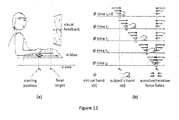
Figure 13 shows a further enhancement of the present invention. - The preferred embodiments of the present invention may provide an apparatus for upper body movement, specifically for elbows and shoulders. The apparatus can be used for applications such as, for example, surgical training, tele-operation, game playing, and most pertinently, rehabilitation. For example, a surgeon grasps a manipulator's handle of the apparatus as if it were a scalpel, and a virtual organ is displayed on a computer screen. The surgeon then moves the handle as if he were cutting the organ with a scalpel. The apparatus then records the trajectory/force and the apparatus can introduce disturbances along the path to simulate anomalies in the organ. Although the apparatus is not suitable to all patients (e.g. the severely impaired ones) undergoing rehabilitation, a large proportion of patients will be able to benefit from use of the apparatus. The low cost to fabricate the apparatus ensures that the apparatus is able to be readily deployed in hospitals, community centres and private homes. Furthermore, the apparatus complements current robotic therapies and allows patient-robot interaction, enabling early discharge and continuous monitoring/training of patients.
-
Figure 6 shows a schematic top view of the apparatus 20 (in this instance used for upper body rehabilitation),Figure 9 shows the schematic diagram of theapparatus 20 andFigure 10 shows a photograph of an example implementation of theapparatus 20. Theapparatus 20 includes ahandle 36 on amanipulandum 22, a six degree of freedom force/torque sensor 23 (for example, ATI Mini40 with 80 N and 4 Nm sensing range), two DC-motors handle 36 is a main component of the apparatus-user interface, but it should be appreciated that thehandle 36 need not be a separate object. Themanipulandum 22 can be shaped in a physical form which facilitates gripping by a user's hand. The force/torque sensor 23 is configured to measure the force/torque transmitted between themanipulandum 22 and the user's hand while gripping thehandle 36. - The driver and the PC with a data acquisition system may be scalable down to a microcontroller form. For a haptic device, a data acquisition system is required to read the position of the
manipulandum 22 and to provide instructions to control an output force of themotors manipulandum 22. In our current implementation, a PC with a real-time control platform (dSPACE, Germany) is used to read the position of the manipulandum 22 (via a linear encoder attached to themotors 24, 26) and to send an output signal to control the output current to themotors - The force transmission from DC-
motors manipulandum 22 is carried out through an H-shaped cable-drivenmechanism 28. It may be possible, according to an example which is not part of the invention, to adopt an A-shaped cable-driven mechanism, but such a shape would introduce more issues/complexity, such as, for example, asymmetric friction, position-dependant impedance, more complex kinematics and so forth. The DC-motors pulleys motors cable 32 which is routed through eight idler pulleys 30 (for example, diameter of 20 mm with 6 mm bearing inside, Misumi AFBD9-20) in the H-shaped cable-drivenmechanism 28. Ultimately the force is directly transferred to the carriages (and ultimately the manipulandum 22), with minimal friction losses. - The handle 36 (made from peek rod) is connected rigidly to a horizontal carriage 38. A mounting is fixed to a solid base 40 to mount the six degree of freedom force/torque sensor. The handle 36 (of
sample dimensions 25 mm x 65 mm) is mounted on top of the six degree of freedom force/torque sensor 23. The solid base 40 is mounted to the horizontal carriage 38. Themanipulandum 22 also includes four idler pulleys 30 (from the eightidler pulleys 30 mentioned earlier) and twovertical carriages 39. - The
apparatus 20 has a configuration in a form of a differential mechanism which enables independent movement of themanipulandum 22 along x and y axes despite having just one cable loop. Another advantage of this configuration is that both actuators are grounded hence a user holding themanipulandum 22 experiences low inertia. Moreover, a Cartesian approach in themanipulandum 22 is obtained by the linear guides/rails of the H-shaped cable-drivenmechanism 28. This configuration ensures homogeneous inertia and friction throughout a whole workspace of theapparatus 20. - The
apparatus 20 is configured to provide planar (i.e. in the xy plane) differential motion. A differential mechanism is a device that produces resultant motion as sum or difference of the component motions, an example of cabled differential for rotary motions can be found in [Sal93]. In theapparatus 20, one movement in one axis is obtained by the sum of the rotation of the motors, while the other is obtained by the difference. This differential movement is represented graphically inFigure 7 . To produce movement in the x axis, DC-motors Figure 7(a) shows both DC-motors manipulandum 22 in a positive x direction and inFigure 7(b) , both DC-motors manipulandum 22 in positive y direction. It should be noted that during x axis movement, only the horizontal carriage 38 moves (together with thehandle 36 and force/torque sensor 23). However for y axis movement, the moving parts are more, i.e. allcarriages 38, 39 with 4 idler pulleys 30. Hence, in order to reduce the inertia experienced by the user, lightweight components are necessary. It should be appreciated that themotors - The
apparatus 20 sits on an aluminum table structure (for example, a 30 x 60 mm aluminum frame), and is suitable for table-top use. Two sets of lightweight stainless steel parallel rails, one on top of the other, are used to implement a 2D Cartesian mechanism.Vertical rails 50 allow for movement of themanipulandum 22 in Y axis, and may be 470 mm long miniature linear guides from Misumi (SSELB13-470), mounted 108 mm apart on a 6 mm clear plastic plate. Horizontal rails 52 mounted above thevertical rails 50 allow for movement of themanipulandum 22 in X axis, and may be 275 mm long miniature linear guides from Misumi (SEBZ10-275). The smaller set of rails 52 contributes to the total inertia that the subject has to move for movement in y axis. In this example, by leaving out the length of the carriage (45 mm) and end stoppers at the linear guides, the total Cartesian work space of the mechanism is 221 mm (x) x 441 mm (y). - An H configuration of
cable 32 is required for the differential driving system for themechanism 28 with two drivingmotors Figure 10 , the H-shaped cable-drivenmechanism 28 is constructed using eightidler pulleys 30, four of which are fixed to two T-shaped custom made mounting plates (as shown inFigure 10(a) ) which are fixed at the bottom side of the top rails. Six mm male end threaded cantilever shafts are used to fix thepulleys 30 to the mounting plates. The other fouridler pulleys 30 are installed at the 4 ends of themechanism 28, three of which are fixed to the aluminum table structure while one at the bottom right hand side is mounted on top of the lead screw guide unit (for example, Misumi XKNEJ20, as shown inFigure 10(b) ) to enable the adjustment of pretension of thecable 32. Clear plastic spacers are used to adjust the height of the idler pulleys 30 to align the grooves of the idler pulleys 30 into a single horizontal plane. The use of spacers ensures that thecable 32 is maintained in a substantially horizontal plane to minimize vertical loading of the idler pulleys 30 which will cause additional friction. - For the actuation of the
mechanism 28, the driving pulleys 25, 27 (for example, having diameter 27.5 mm) are used at the middle in tangent to the long side of the outer cable line of themechanism 28. The driving pulleys 25, 27 are mounted on a clear plastic plate with a double bearing unit (for example, Misumi BGCBB623ZZ-20) driving shaft. Themotors Figures 10(c) and 10(d) respectively). A six mm coupler (for example, Misumi MCO15-6) connects themotors motors pulleys manipulandum 22 will only be able to move at one speed/trajectory. For example, if the driving pulleys 25, 27 are coupled with a 1:1 transmission, themanipulandum 22 will only move in a left-right manner. If the driving pulleys 25, 27 are coupled with a -1:1 transmission, themanipulandum 22 will only move in an up-down manner. If the driving pulleys 25, 27 are coupled with a 1:2 transmission, themanipulandum 22 will only be able to move along a straight line at a pre-defined angle. It should be appreciated that varying the gear ratios (akin to a continuous variable transmission gear system in cars) would require a second motor. - In this embodiment, 0.54 mm nylon coated steel wire rope (7x7) (for example, Asahi Intecc NB45-61) was selected for the
cable 32. Due to its flexibility, it is easy to combine it for use with small pulleys like those used in themechanism 28, hence allowing the possibility to scale down the working space with minimum effort. Thecable 32 is routed through eight pulleys as shown inFig. 9 to form an H configuration and is wrapped at least four turns around the each drivingpulley 25, 27 (as shown inFigure 10(e) ). The more turns around each drivingpulley pulley cable 32. The friction provided from the at least four turns of thecable 32 at each drivingpulley handle 36 when both drivingpulleys cable 32 are fixed to a bottom mounting plate of a torque sensor at a distal side of themechanism 28. - As an example, Faulhaber's DC Micromotors (3863H012C) are chosen to drive the
manipulandum 22. They are light and compact (400 gram, 38 mm diameter, 63 mm length) but it can produce significant amount of torque (1424 mNm stall torque). By attaching a 27.5 mm diameter pulley to the motor shaft, 25 N force can be generated by each motor to move the driving pulley. This amount of force is at the same order as the arm force to move the handle in general, though still below what the arm can produce maximally. For rehabilitation purpose, a more powerful motor may be needed if for example the patient has a very minimum muscle power and the robot is required to assist his/her motion to achieve a certain goal. For motor control experiments, the force generated by this particular setup is sufficient to provide perturbation. - To drive the motor,
Faulhaber 4 quadrant PWM motion controller (MCDC3006, 65 x 58 x 27.5 mm3) may be used. It has its own ROM, an RS232 interface, and an analog input so that it can be programmed to accept a voltage input to be used as the voltage sent to the motor. Using a simple DC motor allows control of current supply by controlling the voltage sent to the motor. - Faulhaber optical encoder (HEDL5540) may be attached to the shaft of each motor. It has a resolution of 500 lines per revolution, thus for a 27.5 mm pulley diameter, its resolution is <0.2 mm in the xy plane. The encoder count is acquired through an input port on the dSPACE system. The dSPACE system is then programmed to provide an analog output which controls the voltage to be sent to the motor through the driver. The programming is done using Simulink and the program is compiled to the dSPACE memory with Simulink Coder.
- Due to the differential mechanism of the
apparatus 20, the forces at the end-effector depend on the torque generated at the motor shaft according to the following equations:

Figure 6 , and the variables with L and R subscript are with respect to the DC-motors motors motors handle 36. The variable r is the radius of the driving pulleys 25, 27 attached to the motor shaft, i.e. 0.5∗25.5mm = 13.75 mm. - A possible family of perturbation force fields is the velocity dependent fields, which can comprises damping and/or Coriolis' fields. In both cases the force FH at the handle is proportional to the handle velocity vH

- The perturbation B in our setup may consist of two components, Coriolis field - Bc, and damping field - Bd, parameterized as α and β

- Substituting eqs (1) and (2) to (3), we can rewrite the perturbation equation with respect to the motors

- Hence once we obtain the angular velocity of the shaft of the DC-
motors motors motors 
Fig. 7 ). - In conclusion, the feedforward model is

- As mentioned earlier, the motor driver only supports voltage control and not current control. So we have to provide a model relating the current and voltage. Based on classical DC motor models, as shown in
Figure 12 , the following equations can be applicable for the 2-motor system:
- Putting everything together in equation, we have the feedforward model

- A basic requirement for the next generation of the
apparatus 20 is the possibility to implement adaptive impedance control which is currently used in commercial MIT-MANUS and which is key to the Performance-Based Progressive Therapy (PBPT) used on the largest clinical study (127 patients) with a MIT-MANUS [Lo10] to date. This approach incorporates the concept of 'assist-as-needed' whereby the patient attempts a movement and the therapist manually helps complete the movement, only when needed. - The details of the adaptive impedance control are fully described in [Kre03], here we will just recall the basic characteristics. Subjects are asked to perform goal-directed reaching, as shown in
Fig. 12-a , from a central target (x0) to a peripheral target (xT). - Healthy subjects are known to perform reaching movements along straight lines and following a so-called minimum-jerk trajectory [Kre03]:

- Impaired subjects, in general, will neither follow straight lines nor move along smooth trajectories. Some subjects might not even be able to start moving and will require assistance. Unlike standard industrial robotic devices, robots such as the MIT-MANUS and the
apparatus 20 will be able to generate impedance-like force fields to guide the movement, just like a therapist guiding the patient hand-in-hand. - The trajectory s(t) can be seen as a 'virtual hand', moving from x0 to xT. If the subject is able to move fast enough, his/her hand would in general move ahead of the virtual hand. If a subject is unable to move or is too slow, the position of the subject's hand x(t) at a certain time t will lag behind the virtual hand s(t).
Figure 13(a) shows theapparatus 20 in use. - As shown in
Figure 13(b) , whenever x(t) lags behind s(t) the subject will experience an assistive force field (). If a subject overshoots the target, he/she would then experience a resistive force field ( ). Similarly, lateral fields (acting perpendicularly to the x-direction, but not shown in
Figure 13 ) will help the subject follow straight lines. - The force fields implemented in the impedance controller are a combination of elastic and damping fields. Damping fields produce torques proportional, via a coefficient typically set around B=10Ns/m, to movement speed and always against the actual movement direction. Also for very jerky motions, speed will rarely exceed 20cm/s, therefore damping torques will rarely exceed 2N (approximately 0.2 Kg of force) which can be considered a very low force. On the other hand, elastic fields might produce much larger forces, depending on the specific subject, and this needs to be taken into account in the early phases of design as well as recruitment. For example, the assistive field () in
Figure 13(b) schematically represents the field of a virtual spring connected between the subject's hand at position x(t) and the virtual hand at position s(t). The virtual spring implemented in the MIT-MANUS has a stiffness coefficient k=200N/m, so that an elastic force F=k∗(x-s), i.e. a force proportional to the distance between subject's hand (x) and virtual hand(s). Peripheral targets are 15cm away from the central target. This means that if a severely impaired subject is unable to move towards a target, the virtual spring should generate forces as high as 200N/m∗15cm = 30N, i.e. approximately 3Kg of force. - This is a considerable amount of force, in fact close to the limits of the
apparatus 20. Larger forces require larger motors, making the system more expensive and less safe. As theapparatus 20 is meant for subjects with mild impairments who would require some level of assistance but who would still be able to move, smaller motors would be preferable. - The behavior of the user (e.g. speed, jerkiness and so forth) will be monitored during the task. The movement time of the virtual hand tf, can be adjusted from trial to trial in order to assist-as-needed or to challenge the subject to do better/faster. Krebs et al [Kre03] describe in detail the adaptive algorithm used to tune the reaching time tf to a specific subject's needs, based on his/her performance during previous trials. This concept is at the basis of the Performance-Based Progressive Therapy.
- A fundamental part of the robot-aided therapy is the goal-directed therapeutic gaming aspect, which is used to motivate and guide the patient through the training session. A possible rehabilitation scenario is shown in
Figure 5 whereby the apparatus can be placed on an inclined surface. It should be appreciated that due to homogeneous inertia, a simple counter weight can be used to balance against gravity when using the inclined surface. The user sits in front of theapparatus 20 and faces a computer screen with a video-game which motivates and guides the user through a series of motor tasks, typically reaching peripheral targets starting from a central one. Healthy subjects are expected to perform reaching tasks by moving along straight lines, with theapparatus 20 being used to generate assistive/resistive force fields to correct the trajectories of the user, as described in the preceding paragraphs. - The
apparatus 20 can be easily manufactured mostly with off-the-shelf components and via a microcontroller, implementing the real-time control, connected to a regular PC (where the video games would be implemented). With its low cost, multiple systems can be employed in hospitals or even community centres, enabling step-down care. It is possible to separate the software for the control of the robot from the user interface. The robotic platform can be made portable with a serial port connectivity as its output. This serial port can be connected directly to any computer which has the user interface software installed within. Hence an understanding of the user interface and of theapparatus 20 is all which is required. - The use of the planar differential mechanism used in the
apparatus 20 provides the following advantages: - i. The user will experience the same inertia, friction, and damping in every point of the workspace, i.e. homogeneous impedance. This feature is not necessarily available in any robotic manipulandum and non-homogenous impedance might lead to arm trajectories which are curved rather than straight as expected, for example, during reaching tasks.
- ii. Another significant advantage of having this type of Cartesian differential mechanism is the simplicity of the mechanism resulting in easier control. It will be shown later that the calculations for controlling the mechanism involve only simple algebra without any trigonometric/logarithmic functions or online matrix inversions. As a result, a simple microcontroller can execute all the operations in real time, hence reducing the complexity and therefore the cost of the system.
- iii. Finally, the so-called "force channels" can be implemented by means of simple mechanical stops. Some experimental paradigms make use of force channels to guide the subject's arm along predefined straight lines (e.g. horizontal, vertical, or oblique). Typically, the channel is implemented by actively, i.e. by means of very powerful actuators which generate canyon-like potentials with steep walls to allow motion only along the canyon, e.g. see [Krebs03]. When using the
apparatus 20, channels in four different directions are passively obtained by mechanical stops. The actuator does not need to be oversized to generate large channel forces, hence increasing the safety of the system by using low power actuators. Four channels are available in our system (seeFigure 8 ), the horizontal and vertical channels are obtained by mechanically blocking the carriages, while the 45° channels by blocking the driving pulleys or motor shafts. Passive vertical and horizontal channels are possible only in Cartesian mechanisms like theapparatus 20. Oblique channels are a direct consequence of the differential transmission. - Unlike conventional machines or robots which are based on complex designs (often readapting industrial mechanisms) to match all possible conditions and severities of impairments, the
apparatus 20 has been primarily conceived to be intrinsically lightweight, portable and simple. In particular, its mechanism makes use of the planar cabled differential with properties potentially beneficial to rehabilitation: - a) lightweight and therefore portable: as only these characteristics will allow use in remote locations and at home.
- b) low-cost and therefore accessible: If only few and specialized clinics can afford (at most) one robot, only few patients will have access to it and for a very limited time.
- c) intrinsically simple and safe: complex and strong robots can harm and therefore require highly trained personnel to be operated.
- Whilst there have been described in the foregoing description preferred embodiments of the present invention, it will be understood by those skilled in the technology concerned that many variations or modifications in details of design or construction may be made without departing from the present invention, which is defined by the appended claims.
-
- [Bre07]
- Brewer BR, McDowell SK, Worthen-Chaudhari LC (2007) Poststroke Upper Extremity Rehabilitation: A Review of Robotic Systems and Clinical Results. Topics in Stroke Rehabilitation 14(6):22-44
- [Cam09]
- Campolo D, Accoto D, Formica D, Guglielmelli E (2009) Intrinsic Constraints of Neural Origin: Assessment and Application to Rehabilitation Robotics. IEEE Trans. on Robotics (Special Issue on 'Rehabilitation Robotics') 25(3):492-501
- [Casa09]
- Casadio M, Giannoni P, Morasso P, Sanguineti V (2009) A proof of concept study for the integration of robot therapy with physiotherapy in the treatment of stroke patients. Clin Rehabil 23: 217-228
- [Col08]
- Colombo R, Pisano F, Micera S, Mazzone A, Delconte C, Carrozza MC, Dario P, Minuco G (2008) Assessing Mechanisms of Recovery During Robot-Aided Neurorehabilitation of the Upper Limb, Neurorehab. and Neural Repair, 22:50-63.
- [Dip07]
- L. Dipietro, H. I. Krebs, S. E. Fasoli, B. T. Volpe, J. Stein, C. Bever and N. Hogan (2007) Changing Motor Synergies in Chronic Stroke. Neurophysiol 98:757-768.
- [Gurg00]
- C.G. Burgar, P.S. Lum, P.C. Shor, M. Van der Loos (2000) Development of robots for rehabilitation therapy: the Palo Alto VA/Stanford experience. J Rehabilitation Research and Development 37:663-73.
- [Hess08]
- S Hesse, C Werner, M Pohl, J Mehrholz, U Puzich, and HI Krebs (2008) Mechanical arm trainer for the treatment of the severely affected arm after a stroke: a single-blinded randomized trial in two centers," Am J Phys Med Rehab 87(10):779-88.
- [Kahn06]
- LE Kahn, ML Zygman, WZ Rymer, DJ Reinkensmeyer (2006) Robot-assisted reaching exercise promotes arm movement recovery in chronic hemiparetic stroke: a randomized controlled pilot study, J Neuroeng Rehabil, 3(12)
- [Kre03]
- HI Krebs et al (2003) Rehabilitation Robotics: Performance-Based Progressive Robot-Assisted Therapy, Autonomous Robots 15, 7-20.
- [Kwak07]
- Kwakkel G, Kollen B (2007) Predicting improvement in the upper paretic limb after stroke: A longitudinal prospective study. Restorative Neurology and Neuroscience 25:453-460
- [Lang07]
- Langhorne P, Widen-Holmqvist L (2007), Early supported discharge after stroke, Journal of Rehabilitation Medicine, 39:103-108.
- [Lo10]
- Lo et al. (2010) Robot-assisted therapy for long-term upper-limb impairment after stroke, New Engl J Med 362(19):1772-83
- [Lum02]
- P. Lum, D.J. Reinkensmeyer, R. Mahoney, W.Z. Rymer, C. Burgar (2002) Robotic devices for movement therapy after stroke: current status and challenges to clinical acceptance. Top Stroke Rehabilitation 8:40-53
- [Lu11a]
- Lu EC, Wang RH, Hebert D, Boger J, Galea MP, Mihilidis A (2011) The development of an upper limb stroke rehabilitation robot: identification of clinical practices and design requirements through a survey of therapists. Disability and Rehabilitation: Assistive Technology, 6(5): 420-431
- [Lu11b]
- Lu EC, Wang RH, Huq R, Gardner D, Karam P, Zabjek K, Hebert D, Boger J, Mihilidis A (2011) Development of a robotic device for upper limb stroke rehabilitation: A user-centered design approach, PALADYN Journal of Behavioral Robotics 2(4):176-184
- [Mice05]
- S. Micera, M.C. Carrozza, E. Guglielmelli, G. Cappiello, F. Zaccone, C. Freschi, R. Colombo, A. Mazzone, C. Delconte, F. Pisano, G. Minuco, P. Dario (2005) A Simple Robotic System for Neurorehabilitation. Autonomous Robots19:271-284.
- [Mor81]
- P. Morasso (1981) Spatial control of arm movements. Exp Brain Res 42:223-227
- [Rein00]
- D.J. Reinkensmeyer, L.E. Kahn, M. Averbuch, A. McKenna-Cole, B.D. Schmit, W.Z. Rymer (2000) Understanding and treating arm movement impairment after chronic brain injury: progress with the ARM guide, Journal of Rehabilitation Research and Development 37:653-662.
- [Sal93]
- Salisbury JK, Townsend WT (1993). Compact Cable Transmission with Cable Differential.
U.S. Patent No. 5,207,114 . Washington, DC: U.S. Patent and Trademark Office. - [San03]
- Sanguineti, V., Morasso, P., Baratto, L., Brichetto, G., Mancardi, G. L., & Solaro, C. (2003). Cerebellar ataxia: Quantitative assessment and cybernetic interpretation. Human Movement Science, 22, 189-205.
- [Sch00]
- T Schallert, JL Leasure, B Kolb (2000) Experience-associated structural events, subependymal cellular proliferative activity, and functional recovery after injury to the central nervous system," J Cerebr Blood F Met, 20(11):1513-1528.
- [Kre06]
- HI Krebs, N Hogan (2006) Therapeautic Robotics: a technology push. Proceedings of the IEEE. 94(9):1727-1738
- [Kre98]
- H.I. Krebs, N. Hogan, M.L. Aisen, B.T. Volpe (1998) Robot-aided neurorehabilitation, IEEE Transactions on Rehabilitation Engineering 6:75-87.
- [Vol00]
- B.T. Volpe, H.I. Krebs, N. Hogan, L. Edelstein, C. Diels, M. Aisen (2000) A novel approach to stroke rehabilitation: robot-aided sensorimotor stimulation. Neurology 54:1938-1944.
Claims (9)
- A rehabilitation patient-robot interaction apparatus (20) for upper body movement, the apparatus comprising:a H-shaped cable-driven mechanism (28);two motors (24, 26) for driving the H-shaped cable-driven mechanism, a driving pulley (25, 27) coupled to each motor;a plurality of guides (52, 50) arranged along the x and y axes;a manipulandum (22) coupled to the H-shaped cable-driven mechanism for independent movement along x and y axes, characterized in that,the manipulandum includes:a horizontal carriage (38);a solid base (40) mounted to the horizontal carriage;a six degree of freedom force/torque sensor (23) mounted to the solid base;a plurality of idler pulleys (30);and a plurality of vertical carriages (39); the H-shaped cable-driven mechanism comprises only one cable; andfour force channels are available, horizontal and vertical channels being passively obtained by providing mechanical stops on the vertical and horizontal carriages respectively to mechanically block the vertical and horizontal carriages respectively, and 45° channels being passively obtained by providing mechanical stops on one of the driving pulleys to block the driving pulley.
- The apparatus of claim 1, wherein the H-shaped mechanism is configured in a form of a differential mechanism such that a user holding the manipulandum experiences low inertia.
- The apparatus of claim 1, wherein the manipulandum further includes a handle (36).
- The apparatus of claim 3, wherein the handle is a separate part of the manipulandum.
- The apparatus of claim 1, wherein the cable is wound at least four turns around the driving pulley coupled to each motor.
- The apparatus of any one of claims 1 to 5, wherein the two motors are controlled by a motor driver.
- The apparatus of any one of claims 1 to 6, wherein a driving force of the two DC motors is determined by a position of the manipulandum.
- The apparatus of claim 7, wherein the driving force of the two DC motors is determined using the following equations:


- The apparatus of any one of claims 1 to 8, wherein the motor is of a type selected from a group consisting of: DC motor, AC motor, magnetic linear actuator, and pneumatic linear actuator.
Applications Claiming Priority (2)
| Application Number | Priority Date | Filing Date | Title |
|---|---|---|---|
| US201261735295P | 2012-12-10 | 2012-12-10 | |
| PCT/SG2013/000520 WO2014092645A1 (en) | 2012-12-10 | 2013-12-10 | An apparatus for upper body movement |
Publications (3)
| Publication Number | Publication Date |
|---|---|
| EP2928568A1 EP2928568A1 (en) | 2015-10-14 |
| EP2928568A4 EP2928568A4 (en) | 2016-08-31 |
| EP2928568B1 true EP2928568B1 (en) | 2019-06-19 |
Family
ID=50934751
Family Applications (1)
| Application Number | Title | Priority Date | Filing Date |
|---|---|---|---|
| EP13863356.5A Active EP2928568B1 (en) | 2012-12-10 | 2013-12-10 | An apparatus for upper body movement |
Country Status (4)
| Country | Link |
|---|---|
| US (1) | US9847045B2 (en) |
| EP (1) | EP2928568B1 (en) |
| SG (2) | SG10201704805UA (en) |
| WO (1) | WO2014092645A1 (en) |
Families Citing this family (33)
| Publication number | Priority date | Publication date | Assignee | Title |
|---|---|---|---|---|
| US9847045B2 (en) | 2012-12-10 | 2017-12-19 | Nanyang Technological University | Apparatus for upper body movement |
| US9387588B1 (en) | 2014-08-25 | 2016-07-12 | Google Inc. | Handling gait disturbances with asynchronous timing |
| US9618937B1 (en) | 2014-08-25 | 2017-04-11 | Google Inc. | Slip detection using robotic limbs |
| US9499218B1 (en) | 2014-12-30 | 2016-11-22 | Google Inc. | Mechanically-timed footsteps for a robotic device |
| ITUB20153189A1 (en) * | 2015-08-21 | 2017-02-21 | Ferrari Spa | VEHICLE SIMULATOR WITH TESE ROPE HANDLING SYSTEM |
| US9999803B1 (en) * | 2015-09-14 | 2018-06-19 | Robert Henschel | Orthopedic hand linear and rotation |
| CA2999413C (en) * | 2015-09-23 | 2022-07-19 | Universite Catholique De Louvain | Rehabilitation system and method |
| US9925667B1 (en) | 2016-01-25 | 2018-03-27 | Boston Dynamics, Inc. | Continuous slip recovery |
| US10118696B1 (en) | 2016-03-31 | 2018-11-06 | Steven M. Hoffberg | Steerable rotating projectile |
| JP6418652B2 (en) * | 2016-04-22 | 2018-11-07 | トヨタ自動車株式会社 | Upper limb rehabilitation support apparatus and method for operating the same |
| KR101808137B1 (en) * | 2016-05-27 | 2017-12-13 | 주식회사 네오펙트 | Rehabilitation training apparatus |
| WO2018001348A1 (en) * | 2016-06-30 | 2018-01-04 | 上海傅利叶智能科技有限公司 | Upper limb rehabilitation training machine |
| IT201600107499A1 (en) * | 2016-10-26 | 2018-04-26 | Marco Ceccarelli | Device for motor assistance of the arm |
| JP7004549B2 (en) * | 2017-11-28 | 2022-02-10 | キヤノンファインテックニスカ株式会社 | Exercise training device |
| JP7071820B2 (en) * | 2017-11-28 | 2022-05-19 | キヤノンファインテックニスカ株式会社 | Exercise training device |
| US11712637B1 (en) | 2018-03-23 | 2023-08-01 | Steven M. Hoffberg | Steerable disk or ball |
| GB201806071D0 (en) * | 2018-04-13 | 2018-05-30 | Rolls Royce Power Eng Plc | Apparatus |
| US10561899B2 (en) * | 2018-07-21 | 2020-02-18 | Tiffaney Florentine | Responsive hip stabilization device |
| JP7157979B2 (en) * | 2018-12-07 | 2022-10-21 | キヤノンファインテックニスカ株式会社 | exercise training device |
| IT201800010921A1 (en) | 2018-12-10 | 2020-06-10 | Polibrixia S R L | MOVING-ROTATION MACHINE |
| CN110547948A (en) * | 2019-09-11 | 2019-12-10 | 聊城大学 | Two-shaft movable upper limb rehabilitation device |
| CN110742775B (en) * | 2019-10-12 | 2022-04-12 | 东南大学 | Upper limb active and passive rehabilitation training robot system based on force feedback technology |
| CN111067760B (en) * | 2019-12-31 | 2022-11-08 | 上海机器人产业技术研究院有限公司 | Upper limb rehabilitation training robot based on omnidirectional mobile platform |
| CN111870868B (en) * | 2020-08-13 | 2024-06-04 | 南通铁人运动用品有限公司 | Resistance-adjustable explosive force trainer |
| CN121695462A (en) | 2020-10-08 | 2026-03-20 | F&P科技健身有限公司 | Exercise device |
| IT202000026975A1 (en) | 2020-11-19 | 2022-05-19 | Daniele Cafolla | UPPER LIMBS MOTOR SUPPORT DEVICE |
| CN112587867A (en) * | 2020-12-29 | 2021-04-02 | 西安建筑科技大学 | Interesting upper limb rehabilitation training device for stroke patient |
| CN113288712B (en) * | 2021-05-08 | 2024-03-26 | 傅键炯 | Clinical rehabilitation training device for neurology |
| BE1030388B1 (en) * | 2023-05-17 | 2024-05-15 | Univ Shanghai | A multifunctional upper limb rehabilitation robot and a corresponding rehabilitation method |
| IT202400000156A1 (en) | 2024-01-05 | 2025-07-05 | Marco Ceccarelli | DEVICE FOR ARM MOTOR EXERCISES |
| IT202400001428A1 (en) | 2024-01-25 | 2025-07-25 | Marco Ceccarelli | DEVICE FOR MOTOR ASSISTANCE OF LIMBS |
| IT202400006292A1 (en) * | 2024-03-21 | 2025-09-21 | Giuseppe Carbone | UPPER LIMB ASSISTANCE DEVICE WITH VARIABLE STIFFNESS JOINTS |
| CN121629758A (en) * | 2024-08-28 | 2026-03-10 | 深圳市经纬线科技有限公司 | Portable soft material cutting device |
Family Cites Families (27)
| Publication number | Priority date | Publication date | Assignee | Title |
|---|---|---|---|---|
| US2785941A (en) * | 1953-11-12 | 1957-03-19 | Macklem F Sutherland | Low-inertia plotting-board drive |
| US3505670A (en) * | 1965-12-21 | 1970-04-07 | Calma Co | Graphical data digitizer |
| FR2398937A1 (en) * | 1977-07-25 | 1979-02-23 | Lectra Systemes Sa | DEVICE FOR DRIVING AND MOVING A BEAM BASED ON TWO GUIDE RAILS AND ONE OR MORE TROLLEYS ASSOCIATED WITH THE BEAM |
| US4524520A (en) * | 1983-02-24 | 1985-06-25 | Levy Nessim I | Carriage positioning system |
| US4600083A (en) * | 1984-09-06 | 1986-07-15 | Parent Christopher A | Positioning systems |
| GB2210350A (en) * | 1987-09-25 | 1989-06-07 | Kemble Instr Company Limited | Machine drive system |
| US5207114A (en) | 1988-04-21 | 1993-05-04 | Massachusetts Institute Of Technology | Compact cable transmission with cable differential |
| US5850928A (en) * | 1989-05-02 | 1998-12-22 | Kahlman; Sture | Arrangement for a vertical and horizontal goods hoist |
| GB9301787D0 (en) * | 1993-01-29 | 1993-03-17 | Rice Quentin | X-y drive |
| US5625576A (en) * | 1993-10-01 | 1997-04-29 | Massachusetts Institute Of Technology | Force reflecting haptic interface |
| US6088020A (en) * | 1998-08-12 | 2000-07-11 | Mitsubishi Electric Information Technology Center America, Inc. (Ita) | Haptic device |
| US6046563A (en) * | 1998-08-19 | 2000-04-04 | Moreyra; Manuel R. | Haptic device |
| US6070480A (en) * | 1998-10-09 | 2000-06-06 | Hewlett Packard Company | Differential motor drive for an XY stage |
| US6386513B1 (en) * | 1999-05-13 | 2002-05-14 | Hamayoon Kazerooni | Human power amplifier for lifting load including apparatus for preventing slack in lifting cable |
| US7831292B2 (en) * | 2002-03-06 | 2010-11-09 | Mako Surgical Corp. | Guidance system and method for surgical procedures with improved feedback |
| US7043337B2 (en) * | 2002-09-30 | 2006-05-09 | The Stanley Works | Methods and apparatus for eliminating instability in intelligent assist devices |
| WO2005000537A1 (en) * | 2003-06-25 | 2005-01-06 | Honda Motor Co., Ltd. | Assist transportation method and device |
| US8054289B2 (en) * | 2006-12-01 | 2011-11-08 | Mimic Technologies, Inc. | Methods, apparatus, and article for force feedback based on tension control and tracking through cables |
| US8317730B2 (en) | 2007-02-16 | 2012-11-27 | Rehabtek Llc | Robotic rehabilitation apparatus and method |
| DE602007006513D1 (en) * | 2007-11-12 | 2010-06-24 | Pilz Gmbh & Co Kg | Multi-axis robot for high-speed applications |
| US8317453B2 (en) * | 2008-05-15 | 2012-11-27 | Ray Givens | Compound-arm manipulator |
| WO2010040416A1 (en) * | 2008-10-10 | 2010-04-15 | Fundacion Fatronik | Universal haptic drive system |
| JP5854992B2 (en) * | 2010-07-02 | 2016-02-09 | 株式会社五合 | Operating device and moving device provided with the operating device |
| IT1406207B1 (en) * | 2011-02-21 | 2014-02-14 | Humanware S R L | APTIC ROBOTIC PLANAR DEVICE ON OMNIDIRECTIONAL WHEELS |
| TR201807071T4 (en) | 2011-06-21 | 2018-06-21 | Univ Sabanci | EXTERNAL SKELETON. |
| US9108360B2 (en) * | 2011-09-23 | 2015-08-18 | Stratasys, Inc. | Gantry assembly for use in additive manufacturing system |
| US9847045B2 (en) | 2012-12-10 | 2017-12-19 | Nanyang Technological University | Apparatus for upper body movement |
-
2013
- 2013-12-10 US US14/650,544 patent/US9847045B2/en active Active
- 2013-12-10 SG SG10201704805UA patent/SG10201704805UA/en unknown
- 2013-12-10 SG SG11201504446TA patent/SG11201504446TA/en unknown
- 2013-12-10 EP EP13863356.5A patent/EP2928568B1/en active Active
- 2013-12-10 WO PCT/SG2013/000520 patent/WO2014092645A1/en not_active Ceased
Non-Patent Citations (1)
| Title |
|---|
| None * |
Also Published As
| Publication number | Publication date |
|---|---|
| SG10201704805UA (en) | 2017-07-28 |
| SG11201504446TA (en) | 2015-07-30 |
| WO2014092645A1 (en) | 2014-06-19 |
| EP2928568A4 (en) | 2016-08-31 |
| US9847045B2 (en) | 2017-12-19 |
| EP2928568A1 (en) | 2015-10-14 |
| US20150302777A1 (en) | 2015-10-22 |
Similar Documents
| Publication | Publication Date | Title |
|---|---|---|
| US9847045B2 (en) | Apparatus for upper body movement | |
| Nef et al. | ARMin: a robot for patient-cooperative arm therapy | |
| Oblak et al. | Universal haptic drive: A robot for arm and wrist rehabilitation | |
| Liu et al. | A home-based tele-rehabilitation system with enhanced therapist-patient remote interaction: a feasibility study | |
| CN106456431B (en) | Interactive devices for upper limb rehabilitation, monitoring and/or evaluation | |
| Frisoli et al. | A force-feedback exoskeleton for upper-limb rehabilitation in virtual reality | |
| Bhujel et al. | A comparative study of end-effector and exoskeleton type rehabilitation robots in human upper extremity rehabilitation | |
| CN110997084B (en) | Upper limb exerciser and control method thereof | |
| Krebs et al. | 24 A wrist extension for mit-manus | |
| Huang et al. | Robot-assisted post-stroke motion rehabilitation in upper extremities: a survey | |
| Atlihan et al. | Development of a therapeutic exercise robot for wrist and forearm rehabilitation | |
| Metzger et al. | Design and characterization of the ReHapticKnob, a robot for assessment and therapy of hand function | |
| US20150290071A1 (en) | Multiple Degree of Freedom Portable Rehabilitation System Having DC Motor-Based, Multi-Mode Actuator | |
| Peng et al. | Design of casia-arm: A novel rehabilitation robot for upper limbs | |
| US12605587B2 (en) | Automatic arm training device, system, and method | |
| Song et al. | ULERD-based active training for upper limb rehabilitation | |
| Duc et al. | Study on the Lower Extremity Rehabilitation Device RHleg. | |
| Shen et al. | EXO-UL upper limb robotic exoskeleton system series: from 1 DOF single-arm to (7+ 1) DOFs dual-arm | |
| Song et al. | Implementation of self-rehabilitation for upper limb based on a haptic device and an exoskeleton device | |
| Oyman et al. | Impedance-based control of a cable driven rehabilitation robot | |
| Song et al. | Usability testing of 2D and 3D displays in an immersive upper extremity exercise testbed | |
| Kikuchi et al. | “Hybrid-PLEMO “, rehabilitation system for upper limbs with active/passive force feedback, and its application for facilitation techniques | |
| Masia et al. | Adaptive training strategy of distal movements by means of a wrist-robot | |
| Song et al. | Development of a new compliant exoskeleton device for elbow joint rehabilitation | |
| Bonikowski et al. | New trends in the use of robotic devices in motor rehabilitation of upper limbs |
Legal Events
| Date | Code | Title | Description |
|---|---|---|---|
| PUAI | Public reference made under article 153(3) epc to a published international application that has entered the european phase |
Free format text: ORIGINAL CODE: 0009012 |
|
| 17P | Request for examination filed |
Effective date: 20150608 |
|
| AK | Designated contracting states |
Kind code of ref document: A1 Designated state(s): AL AT BE BG CH CY CZ DE DK EE ES FI FR GB GR HR HU IE IS IT LI LT LU LV MC MK MT NL NO PL PT RO RS SE SI SK SM TR |
|
| AX | Request for extension of the european patent |
Extension state: BA ME |
|
| DAX | Request for extension of the european patent (deleted) | ||
| RA4 | Supplementary search report drawn up and despatched (corrected) |
Effective date: 20160801 |
|
| RIC1 | Information provided on ipc code assigned before grant |
Ipc: A63B 21/078 20060101AFI20160726BHEP Ipc: A63B 23/02 20060101ALI20160726BHEP Ipc: A61B 5/103 20060101ALI20160726BHEP Ipc: A61H 1/02 20060101ALI20160726BHEP Ipc: F16H 55/36 20060101ALI20160726BHEP |
|
| GRAP | Despatch of communication of intention to grant a patent |
Free format text: ORIGINAL CODE: EPIDOSNIGR1 |
|
| STAA | Information on the status of an ep patent application or granted ep patent |
Free format text: STATUS: GRANT OF PATENT IS INTENDED |
|
| INTG | Intention to grant announced |
Effective date: 20190103 |
|
| GRAS | Grant fee paid |
Free format text: ORIGINAL CODE: EPIDOSNIGR3 |
|
| GRAA | (expected) grant |
Free format text: ORIGINAL CODE: 0009210 |
|
| STAA | Information on the status of an ep patent application or granted ep patent |
Free format text: STATUS: THE PATENT HAS BEEN GRANTED |
|
| AK | Designated contracting states |
Kind code of ref document: B1 Designated state(s): AL AT BE BG CH CY CZ DE DK EE ES FI FR GB GR HR HU IE IS IT LI LT LU LV MC MK MT NL NO PL PT RO RS SE SI SK SM TR |
|
| REG | Reference to a national code |
Ref country code: GB Ref legal event code: FG4D |
|
| REG | Reference to a national code |
Ref country code: CH Ref legal event code: EP |
|
| REG | Reference to a national code |
Ref country code: IE Ref legal event code: FG4D |
|
| REG | Reference to a national code |
Ref country code: AT Ref legal event code: REF Ref document number: 1144739 Country of ref document: AT Kind code of ref document: T Effective date: 20190715 |
|
| REG | Reference to a national code |
Ref country code: DE Ref legal event code: R096 Ref document number: 602013056945 Country of ref document: DE |
|
| REG | Reference to a national code |
Ref country code: NL Ref legal event code: MP Effective date: 20190619 |
|
| PG25 | Lapsed in a contracting state [announced via postgrant information from national office to epo] |
Ref country code: SE Free format text: LAPSE BECAUSE OF FAILURE TO SUBMIT A TRANSLATION OF THE DESCRIPTION OR TO PAY THE FEE WITHIN THE PRESCRIBED TIME-LIMIT Effective date: 20190619 Ref country code: LT Free format text: LAPSE BECAUSE OF FAILURE TO SUBMIT A TRANSLATION OF THE DESCRIPTION OR TO PAY THE FEE WITHIN THE PRESCRIBED TIME-LIMIT Effective date: 20190619 Ref country code: FI Free format text: LAPSE BECAUSE OF FAILURE TO SUBMIT A TRANSLATION OF THE DESCRIPTION OR TO PAY THE FEE WITHIN THE PRESCRIBED TIME-LIMIT Effective date: 20190619 Ref country code: NO Free format text: LAPSE BECAUSE OF FAILURE TO SUBMIT A TRANSLATION OF THE DESCRIPTION OR TO PAY THE FEE WITHIN THE PRESCRIBED TIME-LIMIT Effective date: 20190919 Ref country code: AL Free format text: LAPSE BECAUSE OF FAILURE TO SUBMIT A TRANSLATION OF THE DESCRIPTION OR TO PAY THE FEE WITHIN THE PRESCRIBED TIME-LIMIT Effective date: 20190619 Ref country code: HR Free format text: LAPSE BECAUSE OF FAILURE TO SUBMIT A TRANSLATION OF THE DESCRIPTION OR TO PAY THE FEE WITHIN THE PRESCRIBED TIME-LIMIT Effective date: 20190619 |
|
| REG | Reference to a national code |
Ref country code: LT Ref legal event code: MG4D |
|
| PG25 | Lapsed in a contracting state [announced via postgrant information from national office to epo] |
Ref country code: BG Free format text: LAPSE BECAUSE OF FAILURE TO SUBMIT A TRANSLATION OF THE DESCRIPTION OR TO PAY THE FEE WITHIN THE PRESCRIBED TIME-LIMIT Effective date: 20190919 Ref country code: LV Free format text: LAPSE BECAUSE OF FAILURE TO SUBMIT A TRANSLATION OF THE DESCRIPTION OR TO PAY THE FEE WITHIN THE PRESCRIBED TIME-LIMIT Effective date: 20190619 Ref country code: GR Free format text: LAPSE BECAUSE OF FAILURE TO SUBMIT A TRANSLATION OF THE DESCRIPTION OR TO PAY THE FEE WITHIN THE PRESCRIBED TIME-LIMIT Effective date: 20190920 Ref country code: RS Free format text: LAPSE BECAUSE OF FAILURE TO SUBMIT A TRANSLATION OF THE DESCRIPTION OR TO PAY THE FEE WITHIN THE PRESCRIBED TIME-LIMIT Effective date: 20190619 |
|
| REG | Reference to a national code |
Ref country code: AT Ref legal event code: MK05 Ref document number: 1144739 Country of ref document: AT Kind code of ref document: T Effective date: 20190619 |
|
| PG25 | Lapsed in a contracting state [announced via postgrant information from national office to epo] |
Ref country code: PT Free format text: LAPSE BECAUSE OF FAILURE TO SUBMIT A TRANSLATION OF THE DESCRIPTION OR TO PAY THE FEE WITHIN THE PRESCRIBED TIME-LIMIT Effective date: 20191021 Ref country code: EE Free format text: LAPSE BECAUSE OF FAILURE TO SUBMIT A TRANSLATION OF THE DESCRIPTION OR TO PAY THE FEE WITHIN THE PRESCRIBED TIME-LIMIT Effective date: 20190619 Ref country code: AT Free format text: LAPSE BECAUSE OF FAILURE TO SUBMIT A TRANSLATION OF THE DESCRIPTION OR TO PAY THE FEE WITHIN THE PRESCRIBED TIME-LIMIT Effective date: 20190619 Ref country code: NL Free format text: LAPSE BECAUSE OF FAILURE TO SUBMIT A TRANSLATION OF THE DESCRIPTION OR TO PAY THE FEE WITHIN THE PRESCRIBED TIME-LIMIT Effective date: 20190619 Ref country code: CZ Free format text: LAPSE BECAUSE OF FAILURE TO SUBMIT A TRANSLATION OF THE DESCRIPTION OR TO PAY THE FEE WITHIN THE PRESCRIBED TIME-LIMIT Effective date: 20190619 Ref country code: RO Free format text: LAPSE BECAUSE OF FAILURE TO SUBMIT A TRANSLATION OF THE DESCRIPTION OR TO PAY THE FEE WITHIN THE PRESCRIBED TIME-LIMIT Effective date: 20190619 Ref country code: SK Free format text: LAPSE BECAUSE OF FAILURE TO SUBMIT A TRANSLATION OF THE DESCRIPTION OR TO PAY THE FEE WITHIN THE PRESCRIBED TIME-LIMIT Effective date: 20190619 |
|
| PG25 | Lapsed in a contracting state [announced via postgrant information from national office to epo] |
Ref country code: IS Free format text: LAPSE BECAUSE OF FAILURE TO SUBMIT A TRANSLATION OF THE DESCRIPTION OR TO PAY THE FEE WITHIN THE PRESCRIBED TIME-LIMIT Effective date: 20191019 Ref country code: SM Free format text: LAPSE BECAUSE OF FAILURE TO SUBMIT A TRANSLATION OF THE DESCRIPTION OR TO PAY THE FEE WITHIN THE PRESCRIBED TIME-LIMIT Effective date: 20190619 Ref country code: ES Free format text: LAPSE BECAUSE OF FAILURE TO SUBMIT A TRANSLATION OF THE DESCRIPTION OR TO PAY THE FEE WITHIN THE PRESCRIBED TIME-LIMIT Effective date: 20190619 |
|
| PG25 | Lapsed in a contracting state [announced via postgrant information from national office to epo] |
Ref country code: TR Free format text: LAPSE BECAUSE OF FAILURE TO SUBMIT A TRANSLATION OF THE DESCRIPTION OR TO PAY THE FEE WITHIN THE PRESCRIBED TIME-LIMIT Effective date: 20190619 |
|
| PG25 | Lapsed in a contracting state [announced via postgrant information from national office to epo] |
Ref country code: DK Free format text: LAPSE BECAUSE OF FAILURE TO SUBMIT A TRANSLATION OF THE DESCRIPTION OR TO PAY THE FEE WITHIN THE PRESCRIBED TIME-LIMIT Effective date: 20190619 Ref country code: PL Free format text: LAPSE BECAUSE OF FAILURE TO SUBMIT A TRANSLATION OF THE DESCRIPTION OR TO PAY THE FEE WITHIN THE PRESCRIBED TIME-LIMIT Effective date: 20190619 |
|
| PG25 | Lapsed in a contracting state [announced via postgrant information from national office to epo] |
Ref country code: IS Free format text: LAPSE BECAUSE OF FAILURE TO SUBMIT A TRANSLATION OF THE DESCRIPTION OR TO PAY THE FEE WITHIN THE PRESCRIBED TIME-LIMIT Effective date: 20200224 |
|
| REG | Reference to a national code |
Ref country code: DE Ref legal event code: R097 Ref document number: 602013056945 Country of ref document: DE |
|
| PLBE | No opposition filed within time limit |
Free format text: ORIGINAL CODE: 0009261 |
|
| STAA | Information on the status of an ep patent application or granted ep patent |
Free format text: STATUS: NO OPPOSITION FILED WITHIN TIME LIMIT |
|
| PG2D | Information on lapse in contracting state deleted |
Ref country code: IS |
|
| REG | Reference to a national code |
Ref country code: CH Ref legal event code: PL |
|
| 26N | No opposition filed |
Effective date: 20200603 |
|
| REG | Reference to a national code |
Ref country code: BE Ref legal event code: MM Effective date: 20191231 |
|
| PG25 | Lapsed in a contracting state [announced via postgrant information from national office to epo] |
Ref country code: SI Free format text: LAPSE BECAUSE OF FAILURE TO SUBMIT A TRANSLATION OF THE DESCRIPTION OR TO PAY THE FEE WITHIN THE PRESCRIBED TIME-LIMIT Effective date: 20190619 Ref country code: MC Free format text: LAPSE BECAUSE OF FAILURE TO SUBMIT A TRANSLATION OF THE DESCRIPTION OR TO PAY THE FEE WITHIN THE PRESCRIBED TIME-LIMIT Effective date: 20190619 |
|
| PG25 | Lapsed in a contracting state [announced via postgrant information from national office to epo] |
Ref country code: IE Free format text: LAPSE BECAUSE OF NON-PAYMENT OF DUE FEES Effective date: 20191210 Ref country code: LU Free format text: LAPSE BECAUSE OF NON-PAYMENT OF DUE FEES Effective date: 20191210 |
|
| PG25 | Lapsed in a contracting state [announced via postgrant information from national office to epo] |
Ref country code: BE Free format text: LAPSE BECAUSE OF NON-PAYMENT OF DUE FEES Effective date: 20191231 Ref country code: CH Free format text: LAPSE BECAUSE OF NON-PAYMENT OF DUE FEES Effective date: 20191231 Ref country code: LI Free format text: LAPSE BECAUSE OF NON-PAYMENT OF DUE FEES Effective date: 20191231 |
|
| PG25 | Lapsed in a contracting state [announced via postgrant information from national office to epo] |
Ref country code: CY Free format text: LAPSE BECAUSE OF FAILURE TO SUBMIT A TRANSLATION OF THE DESCRIPTION OR TO PAY THE FEE WITHIN THE PRESCRIBED TIME-LIMIT Effective date: 20190619 |
|
| PG25 | Lapsed in a contracting state [announced via postgrant information from national office to epo] |
Ref country code: HU Free format text: LAPSE BECAUSE OF FAILURE TO SUBMIT A TRANSLATION OF THE DESCRIPTION OR TO PAY THE FEE WITHIN THE PRESCRIBED TIME-LIMIT; INVALID AB INITIO Effective date: 20131210 Ref country code: MT Free format text: LAPSE BECAUSE OF FAILURE TO SUBMIT A TRANSLATION OF THE DESCRIPTION OR TO PAY THE FEE WITHIN THE PRESCRIBED TIME-LIMIT Effective date: 20190619 |
|
| PG25 | Lapsed in a contracting state [announced via postgrant information from national office to epo] |
Ref country code: MK Free format text: LAPSE BECAUSE OF FAILURE TO SUBMIT A TRANSLATION OF THE DESCRIPTION OR TO PAY THE FEE WITHIN THE PRESCRIBED TIME-LIMIT Effective date: 20190619 |
|
| P01 | Opt-out of the competence of the unified patent court (upc) registered |
Effective date: 20230530 |
|
| PGFP | Annual fee paid to national office [announced via postgrant information from national office to epo] |
Ref country code: GB Payment date: 20231130 Year of fee payment: 11 |
|
| PGFP | Annual fee paid to national office [announced via postgrant information from national office to epo] |
Ref country code: IT Payment date: 20231212 Year of fee payment: 11 |
|
| GBPC | Gb: european patent ceased through non-payment of renewal fee |
Effective date: 20241210 |
|
| PG25 | Lapsed in a contracting state [announced via postgrant information from national office to epo] |
Ref country code: IT Free format text: LAPSE BECAUSE OF NON-PAYMENT OF DUE FEES Effective date: 20241210 |
|
| PG25 | Lapsed in a contracting state [announced via postgrant information from national office to epo] |
Ref country code: GB Free format text: LAPSE BECAUSE OF NON-PAYMENT OF DUE FEES Effective date: 20241210 |
|
| PGFP | Annual fee paid to national office [announced via postgrant information from national office to epo] |
Ref country code: DE Payment date: 20251119 Year of fee payment: 13 |
|
| PGFP | Annual fee paid to national office [announced via postgrant information from national office to epo] |
Ref country code: FR Payment date: 20251124 Year of fee payment: 13 |