EP2928073A1 - Electromagnetic rotating device and vacuum pump equipped with electromagnetic rotating device - Google Patents
Electromagnetic rotating device and vacuum pump equipped with electromagnetic rotating device Download PDFInfo
- Publication number
- EP2928073A1 EP2928073A1 EP13857910.7A EP13857910A EP2928073A1 EP 2928073 A1 EP2928073 A1 EP 2928073A1 EP 13857910 A EP13857910 A EP 13857910A EP 2928073 A1 EP2928073 A1 EP 2928073A1
- Authority
- EP
- European Patent Office
- Prior art keywords
- motor
- current
- circuit
- voltage
- detection signal
- Prior art date
- Legal status (The legal status is an assumption and is not a legal conclusion. Google has not performed a legal analysis and makes no representation as to the accuracy of the status listed.)
- Granted
Links
Images





Classifications
-
- F—MECHANICAL ENGINEERING; LIGHTING; HEATING; WEAPONS; BLASTING
- F04—POSITIVE - DISPLACEMENT MACHINES FOR LIQUIDS; PUMPS FOR LIQUIDS OR ELASTIC FLUIDS
- F04D—NON-POSITIVE-DISPLACEMENT PUMPS
- F04D19/00—Axial-flow pumps
- F04D19/02—Multi-stage pumps
- F04D19/04—Multi-stage pumps specially adapted to the production of a high vacuum, e.g. molecular pumps
- F04D19/048—Multi-stage pumps specially adapted to the production of a high vacuum, e.g. molecular pumps comprising magnetic bearings
-
- F—MECHANICAL ENGINEERING; LIGHTING; HEATING; WEAPONS; BLASTING
- F04—POSITIVE - DISPLACEMENT MACHINES FOR LIQUIDS; PUMPS FOR LIQUIDS OR ELASTIC FLUIDS
- F04D—NON-POSITIVE-DISPLACEMENT PUMPS
- F04D25/00—Pumping installations or systems
- F04D25/02—Units comprising pumps and their driving means
- F04D25/06—Units comprising pumps and their driving means the pump being electrically driven
-
- F—MECHANICAL ENGINEERING; LIGHTING; HEATING; WEAPONS; BLASTING
- F04—POSITIVE - DISPLACEMENT MACHINES FOR LIQUIDS; PUMPS FOR LIQUIDS OR ELASTIC FLUIDS
- F04D—NON-POSITIVE-DISPLACEMENT PUMPS
- F04D25/00—Pumping installations or systems
- F04D25/02—Units comprising pumps and their driving means
- F04D25/06—Units comprising pumps and their driving means the pump being electrically driven
- F04D25/0606—Units comprising pumps and their driving means the pump being electrically driven the electric motor being specially adapted for integration in the pump
-
- F—MECHANICAL ENGINEERING; LIGHTING; HEATING; WEAPONS; BLASTING
- F04—POSITIVE - DISPLACEMENT MACHINES FOR LIQUIDS; PUMPS FOR LIQUIDS OR ELASTIC FLUIDS
- F04D—NON-POSITIVE-DISPLACEMENT PUMPS
- F04D27/00—Control, e.g. regulation, of pumps, pumping installations or pumping systems specially adapted for elastic fluids
-
- F—MECHANICAL ENGINEERING; LIGHTING; HEATING; WEAPONS; BLASTING
- F04—POSITIVE - DISPLACEMENT MACHINES FOR LIQUIDS; PUMPS FOR LIQUIDS OR ELASTIC FLUIDS
- F04D—NON-POSITIVE-DISPLACEMENT PUMPS
- F04D27/00—Control, e.g. regulation, of pumps, pumping installations or pumping systems specially adapted for elastic fluids
- F04D27/02—Surge control
- F04D27/0261—Surge control by varying driving speed
-
- F—MECHANICAL ENGINEERING; LIGHTING; HEATING; WEAPONS; BLASTING
- F04—POSITIVE - DISPLACEMENT MACHINES FOR LIQUIDS; PUMPS FOR LIQUIDS OR ELASTIC FLUIDS
- F04D—NON-POSITIVE-DISPLACEMENT PUMPS
- F04D29/00—Details, component parts, or accessories
- F04D29/05—Shafts or bearings, or assemblies thereof, specially adapted for elastic fluid pumps
- F04D29/053—Shafts
-
- F—MECHANICAL ENGINEERING; LIGHTING; HEATING; WEAPONS; BLASTING
- F04—POSITIVE - DISPLACEMENT MACHINES FOR LIQUIDS; PUMPS FOR LIQUIDS OR ELASTIC FLUIDS
- F04D—NON-POSITIVE-DISPLACEMENT PUMPS
- F04D29/00—Details, component parts, or accessories
- F04D29/05—Shafts or bearings, or assemblies thereof, specially adapted for elastic fluid pumps
- F04D29/056—Bearings
- F04D29/058—Bearings magnetic; electromagnetic
-
- F—MECHANICAL ENGINEERING; LIGHTING; HEATING; WEAPONS; BLASTING
- F16—ENGINEERING ELEMENTS AND UNITS; GENERAL MEASURES FOR PRODUCING AND MAINTAINING EFFECTIVE FUNCTIONING OF MACHINES OR INSTALLATIONS; THERMAL INSULATION IN GENERAL
- F16C—SHAFTS; FLEXIBLE SHAFTS; ELEMENTS OR CRANKSHAFT MECHANISMS; ROTARY BODIES OTHER THAN GEARING ELEMENTS; BEARINGS
- F16C32/00—Bearings not otherwise provided for
- F16C32/04—Bearings not otherwise provided for using magnetic or electric supporting means
- F16C32/0406—Magnetic bearings
- F16C32/044—Active magnetic bearings
- F16C32/0444—Details of devices to control the actuation of the electromagnets
- F16C32/0457—Details of the power supply to the electromagnets
-
- H—ELECTRICITY
- H02—GENERATION; CONVERSION OR DISTRIBUTION OF ELECTRIC POWER
- H02P—CONTROL OR REGULATION OF ELECTRIC MOTORS, ELECTRIC GENERATORS OR DYNAMO-ELECTRIC CONVERTERS; CONTROLLING TRANSFORMERS, REACTORS OR CHOKE COILS
- H02P3/00—Arrangements for stopping or slowing electric motors, generators, or dynamo-electric converters
- H02P3/06—Arrangements for stopping or slowing electric motors, generators, or dynamo-electric converters for stopping or slowing an individual dynamo-electric motor or dynamo-electric converter
- H02P3/08—Arrangements for stopping or slowing electric motors, generators, or dynamo-electric converters for stopping or slowing an individual dynamo-electric motor or dynamo-electric converter for stopping or slowing a DC motor
- H02P3/14—Arrangements for stopping or slowing electric motors, generators, or dynamo-electric converters for stopping or slowing an individual dynamo-electric motor or dynamo-electric converter for stopping or slowing a DC motor by regenerative braking
-
- H—ELECTRICITY
- H02—GENERATION; CONVERSION OR DISTRIBUTION OF ELECTRIC POWER
- H02P—CONTROL OR REGULATION OF ELECTRIC MOTORS, ELECTRIC GENERATORS OR DYNAMO-ELECTRIC CONVERTERS; CONTROLLING TRANSFORMERS, REACTORS OR CHOKE COILS
- H02P3/00—Arrangements for stopping or slowing electric motors, generators, or dynamo-electric converters
- H02P3/06—Arrangements for stopping or slowing electric motors, generators, or dynamo-electric converters for stopping or slowing an individual dynamo-electric motor or dynamo-electric converter
- H02P3/18—Arrangements for stopping or slowing electric motors, generators, or dynamo-electric converters for stopping or slowing an individual dynamo-electric motor or dynamo-electric converter for stopping or slowing an AC motor
-
- H—ELECTRICITY
- H02—GENERATION; CONVERSION OR DISTRIBUTION OF ELECTRIC POWER
- H02P—CONTROL OR REGULATION OF ELECTRIC MOTORS, ELECTRIC GENERATORS OR DYNAMO-ELECTRIC CONVERTERS; CONTROLLING TRANSFORMERS, REACTORS OR CHOKE COILS
- H02P6/00—Arrangements for controlling synchronous motors or other dynamo-electric motors using electronic commutation dependent on the rotor position; Electronic commutators therefor
- H02P6/08—Arrangements for controlling the speed or torque of a single motor
- H02P6/085—Arrangements for controlling the speed or torque of a single motor in a bridge configuration
-
- H—ELECTRICITY
- H02—GENERATION; CONVERSION OR DISTRIBUTION OF ELECTRIC POWER
- H02P—CONTROL OR REGULATION OF ELECTRIC MOTORS, ELECTRIC GENERATORS OR DYNAMO-ELECTRIC CONVERTERS; CONTROLLING TRANSFORMERS, REACTORS OR CHOKE COILS
- H02P6/00—Arrangements for controlling synchronous motors or other dynamo-electric motors using electronic commutation dependent on the rotor position; Electronic commutators therefor
- H02P6/24—Arrangements for stopping
-
- F—MECHANICAL ENGINEERING; LIGHTING; HEATING; WEAPONS; BLASTING
- F16—ENGINEERING ELEMENTS AND UNITS; GENERAL MEASURES FOR PRODUCING AND MAINTAINING EFFECTIVE FUNCTIONING OF MACHINES OR INSTALLATIONS; THERMAL INSULATION IN GENERAL
- F16C—SHAFTS; FLEXIBLE SHAFTS; ELEMENTS OR CRANKSHAFT MECHANISMS; ROTARY BODIES OTHER THAN GEARING ELEMENTS; BEARINGS
- F16C2360/00—Engines or pumps
- F16C2360/44—Centrifugal pumps
- F16C2360/45—Turbo-molecular pumps
-
- Y—GENERAL TAGGING OF NEW TECHNOLOGICAL DEVELOPMENTS; GENERAL TAGGING OF CROSS-SECTIONAL TECHNOLOGIES SPANNING OVER SEVERAL SECTIONS OF THE IPC; TECHNICAL SUBJECTS COVERED BY FORMER USPC CROSS-REFERENCE ART COLLECTIONS [XRACs] AND DIGESTS
- Y02—TECHNOLOGIES OR APPLICATIONS FOR MITIGATION OR ADAPTATION AGAINST CLIMATE CHANGE
- Y02B—CLIMATE CHANGE MITIGATION TECHNOLOGIES RELATED TO BUILDINGS, e.g. HOUSING, HOUSE APPLIANCES OR RELATED END-USER APPLICATIONS
- Y02B30/00—Energy efficient heating, ventilation or air conditioning [HVAC]
- Y02B30/70—Efficient control or regulation technologies, e.g. for control of refrigerant flow, motor or heating
Definitions
- the present invention relates to an electromagnetic rotating apparatus and a vacuum pump having the electromagnetic rotating apparatus, and in particular, to an electromagnetic rotating apparatus and a vacuum pump having the electromagnetic rotating apparatus in which power generated during regeneration is consumed by an electromagnet winding in the electromagnetic rotating apparatus to allow a reduction in the size of the apparatus and in costs.
- a vacuum pump is generally used as a pump apparatus.
- a turbo-molecular pump - one type of vacuum pump - is frequency used because of, for example, a lower level of residual gas and high maintainability thereof.
- steps of manufacturing a semiconductor include a large number of steps for allowing various process gases to act on a semiconductor substrate.
- the turbo-molecular pump is used not only to vacuumize the inside of the chamber but also to discharge the process gases from the inside of the chamber.
- the turbo-molecular pump is used in a facility for an electronic microscope or the like to set the environment in a chamber for the electronic microscope or the like to a high vacuum state in order to prevent refraction of electron beams and the like caused by the presence of dust and the like.
- Such a turbo-molecular pump includes a turbo-molecular pump main body that allows the gas to be sucked and discharged from the chamber for a semiconductor manufacturing apparatus, an electronic microscope, or the like and a control apparatus that controls the turbo-molecular pump main body.
- FIG. 9 depicts a longitudinal cross-sectional view of the turbo-molecular pump main body.
- an inlet port 101 is formed at an upper end of a tubular outer cylinder 127.
- a rotor 103 is provided which includes a plurality of rotor blades 102a, 102b, 102c, ... radially formed around a peripheral portion of the rotor at multiple stages, the rotor blades 102a, 102b, 102c, ... being turbine blades allowing the gas to be sucked and discharged.
- a rotor shaft 113 is attached to the center of the rotor 103. The rotor shaft 113 is supported so as to float in the air and subjected to position control, for example, by a magnetic bearing for five-axis control.
- an upper radial electromagnet 104 four electromagnets are arranged such that the electromagnets of each of two pairs of electromagnets are arranged on an X axis and a Y axis and such that the electromagnets of each of different two pairs of electromagnets are arranged in a positive direction and in a negative direction (although not depicted in the drawings, the electromagnets are denoted by 104X+, 104X-, 104Y+, and 104Y-).
- An upper radial sensor 107 including four electromagnets is provided in proximity to and in association with the upper radial electromagnet 104. The upper radial sensor 107 is configured to detect radial displacement of the rotor 103 to transmit the relevant signal to the control apparatus.
- a magnetic bearing control circuit excites and controls the upper radial electromagnet 104 via a compensation circuit with a PID adjustment function to adjust an upper radial position of the rotor shaft 113.
- the rotor shaft 113 is formed of a high-magnetic-permeability material (iron or the like) and attracted by a magnetic force of the upper radial electromagnet 104. Such adjustment is made independently in the direction of the X axis and in the direction of the Y axis.
- a lower radial electromagnet 105 and a lower radial sensor 108 are arranged similarly to the upper radial electromagnet 104 and the upper radial sensor 107 to adjust a lower radial position of the rotor shaft 113 similarly to the upper radial position (for the lower radial electromagnet 105, the electromagnets are denoted by 105X+, 105X-, 105Y+, and 105Y- as needed).
- axial electromagnets 106A and 106B are arranged above and below a disc-shaped metal disc 111 to sandwich the same that is provided below the rotor shaft 113.
- the metal disc 111 is formed of a high-magnetic-permeability material such as iron.
- An axial sensor 109 is provided to detect axial displacement of the rotor shaft 113 so that an axial displacement signal is transmitted to the control apparatus.
- the axial electromagnets 106A and 106B are excited and controlled by the magnetic bearing control circuit via the compensation circuit with the PID adjustment function, the magnetic bearing control circuit and the compensation circuit being included in the control apparatus.
- the axial electromagnet 106A magnetically attracts the metal disc 111 upward.
- the axial electromagnet 106B magnetically attracts the metal disc 111 downward.
- the control apparatus appropriately adjusts the magnetic force applied to the metal disc 111 by the axial electromagnets 106A and 106B to allow the rotor shaft 113 to magnetically float in the axial direction, thus holding the rotor shaft 113 in the space in a non-contact manner.
- the magnetic bearing control circuit exciting and driving the upper radial electromagnet 104, the lower radial electromagnet 105, and the axial electromagnets 106A and 106B will be described below.
- a motor 121 includes a plurality of magnetic poles peripherally arranged so as to surround the rotor shaft 113. Each of the magnetic poles is controlled by the control apparatus so as to rotationally drive the rotor shaft 113 via an electromagnetic force acting between the magnetic pole and the rotor shaft 113.
- a number-of-rotations sensor not depicted in the drawings is incorporated in the motor 121.
- the number of rotations of the rotor shaft 113 is detected based on a detection signal from the number-of-rotations sensor.
- a phase sensor not depicted in the drawings is attached, for example, near the lower radial sensor 108 to detect the phase of rotation of the rotor shaft 113.
- the control apparatus uses detection signals from both the phase sensor and the number-of-rotations sensor to detect the positions of the magnetic poles.
- a plurality of stator blades 123a, 123b, 123c, ... is disposed such that a small void is present between each of the stator blades 123a, 123b, 123c, ... and a corresponding one of the rotor blades 102a, 102b, 102c, ...
- the rotor blades 102a, 102b, 102c, ... are formed to incline at a predetermined angle to a plane perpendicular to the axis of the rotor shaft 113 so as to transfer molecules of exhaust gas downward which collide against the rotor blades 102a, 102b, 102c, ...
- the stator blade 123 is also formed to incline at the predetermined angle from the plane perpendicular to the axis of the rotor shaft 113 and disposed so as to extend to the center of the outer cylinder 127 and so that stages of the stator blade 123 alternate with corresponding stages of the rotor blade 102.
- stator blade 123 One end of the stator blade 123 is supported so as to be fitted and inserted between a plurality of stacked stator blade spacers 125a, 125b, 125c, ...
- the stator blade spacer 125 is a ring-shaped member and is formed of metal, for example, aluminum, iron, stainless steel, or copper, or an alloy containing any of these metals as a component.
- the outer cylinder 127 is fixed around an outer periphery of the stator blade spacer 125 with a small void between the outer cylinder 127 and the stator blade spacer 125.
- a base portion 129 is disposed at a bottom portion of the outer cylinder 127.
- a threaded spacer 131 is disposed between a lower portion of the stator blade spacer 125 and the base portion 129.
- An outlet port 133 is formed in the base portion 129 and below the threaded spacer 131 so as to communicate with the exterior of the apparatus.
- the turbo-molecular pump needs control based on individually adjusted specific parameters (for example, the identity of a machine type and characteristics corresponding to the machine type).
- the turbo-molecular pump main body 100 includes an electronic circuit section 141.
- the electronic circuit section 141 is housed near the center of the base portion 129, which provides a lower portion of the turbo-molecular pump main body 100, and below the number-of-rotations sensor not depicted in the drawings.
- the electronic circuit section 141 is closed by an air-tight bottom cover 145.
- a rectifier circuit 10 converts an alternating current into a direct current as depicted in FIG. 10 .
- the direct current is converted into three phases by a motor driving main circuit 30 based on a pulse signal adjusted by a motor driving control circuit 20 so that the motor 121 is driven by the converted current.
- Power from a rectifier circuit 10 is reduced in voltage by a direct-current stabilizing power supply circuit 40 and then supplied to the motor driving control circuit 20 and to the magnetic bearing control circuit 50.
- the magnetic bearing control circuit 50 passes an excitation current to each of the electromagnets including the upper radial electromagnet 104, the lower radial electromagnet 105, and the axial electromagnets 106A and 106B.
- the excitation current is passed to the pair of electromagnets providing each of the following: the upper radial electromagnet 104, the lower radial electromagnet 105, and the axial electromagnets 106A and 106B, as a constant steady current (bias current) on which a displacement current dependent on a position deviation signal is superimposed.
- a resistor 3 and a transistor 5 located between two power supply lines 1a and 1b are connected to the power supply circuit.
- transistors 7, 9, 11, 13, 15, and 17 are located between the two power supply lines 1a and 1b and connected to the power supply lines 1a and 1b in form of a three-phase bridge connection to provide power supply to the motor 121.
- Diodes 19a to 19g for passage of a regeneration current are each connected between a source and a drain of a corresponding one of the transistors 5 to 17.
- a current flowing through the transistors 9, 13, and 17 is detected by a current detecting section not depicted in the drawings to determine a deviation of the current from a motor current command value. Then, a PWM control signal adjusted based on this deviation is input to a gate of each of the transistors 7, 9, 11, 13, 15, and 17.
- the resistor 3 functions as a regeneration resistor to convert regenerated electric power generated by the motor 121 when the rotor 103 is decelerated, into heat for consumption.
- Japanese Patent Application Laid-open Nos. H7-279962 , 2002-180990 , and 2004-112877 are known as conventional examples that use the regenerative resistance for the vacuum pump as described above.
- An object of the present invention is to provide an electromagnetic rotating apparatus and a vacuum pump having the electromagnetic rotating apparatus in which power generated during regeneration is consumed by an electromagnet winding in the electromagnetic rotating apparatus to allow a reduction in the size of the apparatus and in costs.
- an aspect of the present invention includes a motor; a rotor shaft that is rotationally driven by the motor; an electromagnet through which, as an excitation current, a displacement current generated in accordance with a positional deviation of the rotor shaft and superimposed on a bias current is passed; a power supply that supplies a direct current; a motor driving main circuit that supplies the direct current supplied by the power supply to the motor; a motor voltage monitoring circuit that monitors a voltage of the direct current; detection signal output means for outputting a detection signal when the voltage monitored by the motor voltage monitoring circuit reaches a predetermined value or larger; and a magnetic bearing control circuit that increases the bias current that excites the electromagnet, based on the detection signal that is output by the detection signal output means.
- the bias current in the magnetic bearing is increased to allow regenerated electric power to be consumed by an electromagnet winding in a magnetic bearing apparatus.
- This enables a regeneration resistor to be removed.
- the removal of the regeneration resistor eliminates the need for an installation space for the regeneration resistor, leading to a miniaturized control apparatus. Furthermore, a switching element that turns on and off the regeneration resistor can be made unnecessary, reducing costs.
- claim 2 includes: a motor driving control circuit that controls a motor current passed through the motor in accordance with a command value; and a braking current adjusting circuit that reduces the command value for the motor current, based on the detection signal that is output by the detection signal output means.
- the motor current is adjusted to prevent the voltage from increasing during regeneration or the like. That is, when the voltage to the motor driving main circuit increases, the command value for the motor current is reduced. A reduced current flowing through the motor decreases the voltage during regeneration or the like.
- an aspect of the present invention (claim 3) is characterized in that the power supply supplies the magnetic bearing control circuit with a direct current of a voltage identical to a voltage supplied to the motor driving main circuit.
- a direct-current stabilizing power supply circuit that supplies the direct current to the motor driving control circuit and the magnetic bearing control circuit can be reduced in size.
- an aspect of the present invention is a vacuum pump including the electromagnetic rotating apparatus set forth in any one of claims 1 to 3, characterized in that a rotor blade is attached to the rotor shaft.
- the removal of the regeneration resistor eliminates the need for an installation space for the regeneration resistor, leading to a miniaturized control apparatus. Furthermore, the switching element that turns on and off the regeneration resistor can be made unnecessary, reducing costs.
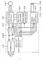
- FIG. 1 depicts a general block diagram of a first embodiment of the present invention. Elements of the first embodiment which are identical to the corresponding elements in FIG. 10 are denoted by identical reference numerals and will not be described below.
- FIG. 1 depicts that an AC power supply is connected to a rectifier circuit 10 in a control apparatus 400.
- the rectifier circuit 10 rectifies and converts an alternating current into a direct current of 100 to 150 V.
- the direct current flows between power supply lines 1a and 1b and is input to a motor driving main circuit 30.
- a motor voltage monitoring circuit 60 is disposed to monitor a voltage at the motor driving main circuit 30.
- the motor voltage monitoring circuit 60 detects that the voltage between the power supply lines 1a and 1b has become higher than a predetermined voltage during deceleration or acceleration of a motor 121.
- the motor voltage monitoring circuit 60 outputs a high-voltage detection signal.
- the high-voltage detection signal is input to a braking current adjusting circuit 70 and a magnetic bearing control circuit 50.
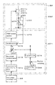
- a braking current command value calculating section 71 depicted in FIG. 2 calculates a command value for a braking current for the motor 121.
- a deviation section 75 determines a deviation of the command value for the braking current calculated by the braking current command value calculating section 71 from a current value detected by a current detecting section 73 disposed in series with transistors 9, 13, and 17.
- a PWM control signal is generated which results from pulse width modulation by a PWM control section 77 based on the deviation.
- the PWM control signal is input to a gate of each of the transistors 7, 9, 11, 13, 15, and 17 in the motor driving main circuit 30 to adjust the braking current.
- a direct current that is output by the rectifier circuit 10 is reduced to approximately several V by a direct-current stabilizing power supply circuit 40.
- the resultant direct current is input to the motor driving control circuit 20 and the magnetic bearing control circuit 50 as a control voltage. Furthermore, the voltage between the power supply lines 1a and 1b is supplied to the magnetic bearing control circuit 50.
- FIG. 3 is a configuration diagram of the magnetic bearing control circuit 50.
- the magnetic bearing control circuit 50 includes an amplifier circuit 250 and an amplifier control circuit 271.
- the control voltage from the direct-current stabilizing power supply circuit 40 is input to the amplifier control circuit 271.
- FIG. 3 depicts that the turbo-molecular pump main body 100 is provided with a node common to electromagnet windings 151 providing electromagnets 104, 105, 106A, and 106B, respectively (the node is hereinafter referred to as the common node C). Furthermore, each electromagnet winding 151 is connected to the common node C at one end 151a of the winding. Additionally, the electromagnet winding 151 is connected to a transistor 261 and a diode 265 in the amplifier circuit 250 at the other end 151b of the winding (a node at the other end 151b is hereinafter referred to as a node E).
- the transistor 261 is a power MOSFET with a drain terminal 261a connected to the other end 151b of the electromagnet winding 151 and a source terminal 261b connected a negative pole 1b of the rectifier circuit 10 via a current detecting circuit 255.
- the diode 265 is a diode for current regeneration or a flywheel including a cathode terminal 265a connected to a positive pole 1a of the rectifier circuit 10 and an anode terminal 265b connected to the other end 151b of the electromagnet winding 151.
- the current detecting circuit 255 connected to the source terminal 261b of the transistor 261 has a detection resistor 256 connected to the negative pole 1b at one end of the resistor and to the source terminal 261b of the transistor 261 at the other end of the resistor, and a detection section 257 that detects an electromagnet current iL in a voltage at the other end of the detection resistor 256.
- the detection section 257 detects the electromagnet current iL flowing through the electromagnet winding 151 to output a current detection signal 273 corresponding to a result of the detection to the amplifier control circuit 271.
- the amplifier circuit 250 configured as described above is provided for each of the electromagnet windings 151 providing the electromagnets 104, 105, 106A, and 106B, respectively.
- the amplifier control circuit 271 is a circuit in a DSP section (not depicted in the drawings).
- the high-voltage detection signal detected by the motor voltage monitoring circuit 60 is input to the amplifier control circuit 271 as depicted in FIG. 4 .
- a current command value calculating section 371 calculates a command value for a bias current passed through the electromagnet winding 151.
- a bias current command value 373 resulting from the calculation by the current command value calculating section 371 is input to a deviation section 375 after being added in an addition section 387 to one of two signals output by a compensation circuit 379, in order to drive an electromagnet 105X+ providing a lower radial electromagnet 105, as depicted in FIG. 4 and a system diagram for control of a radial position in FIG. 5 .
- the other signal that is output by the compensation circuit 379 is inverted by an inversion circuit 381, and the resultant signal is input to the deviation section 375 after being added in the addition section 389 to the bias current command value 373.
- bias current command value is intended to linearly perform radial positional control on a rotor 103. That is, a constant direct bias current and a braking current allowing the rotor 103 to be held in position are passed through the electromagnet 105X+ and the electromagnet 105X- in a superimposed manner.
- the compensation circuit 379 receives, for example, a deviation, from a position command value 385, of the radial position of the rotor 103 detected by a position detecting circuit 383 in a lower radial sensor 108, which deviation has been calculated by a deviation section 341.
- FIG. 4 depicts that the deviation section 375 compares a value for the electromagnet current iL detected by the current detecting circuit 255 with a current command value and that a PWM control section 377 determines a time for which the electromagnet current iL is increased (increase time Tp1 described below) and a time for which the electromagnet current iL is reduced (reduction time Tp2 described below), and based on these times, determines a pulse width time for a gate driving signal 274 output to a gate terminal of the transistor 261 within a control cycle Ts that is one period according to PWM control.
- FIG. 3 depicts that a switching circuit 280 is connected to the common node C in the amplifier circuit 250.
- a transistor 281 and a diode 285 are connected to the common node C.
- the diode 285 is a diode for current regeneration or a flywheel including a cathode terminal 285a connected to the common node C and an anode terminal 285b connected to the negative pole 1b as is the case with the amplifier circuit 250.
- the transistor 281 is a power MOSFET including a drain terminal 281a connected to the positive pole 1a of the rectifier circuit 10 and a source terminal 281b connected to the common node C.
- a switching signal 276 from the amplifier control circuit 271 is output to a gate terminal of the transistor 281.
- the amplifier control circuit 271 determines a pulse width time for the switching signal 276 output to the gate terminal of the transistor 281 within the control cycle Ts as is the case with the control performed on the amplifier circuit 250.
- FIG. 6 depicts a time chart illustrating adjustment of a control phase provided to the transistor 261 and the like by the amplifier circuit 250 and a switching phase provided to the transistor 281 and the like by the switching circuit 280.
- FIG. 6 depicts that the switching circuit 280 is controlled such that, during the control cycle Ts, the time during which the transistor 281 is on is the same as the time during which the transistor 281 is off. In this case, the transistor 281 is on from a point in time corresponding to the beginning of the control cycle Ts (time 0) until a point in time corresponding to the half of the control cycle Ts (time 0.5Ts).
- a voltage at the common node C is substantially the same as a voltage at the negative pole 1b due to, for example, the counter electromotive force generated in the electromagnet winding 151 (this voltage is hereinafter referred to as a voltage VL).
- the transistor 281 is on from a point in time corresponding to the half of the control cycle Ts (time 0.5Ts) until a point in time corresponding to the end of the control cycle Ts (time Ts). Consequently, the voltage at the common node C is substantially the same as a voltage at the positive pole 1a (this voltage is hereinafter referred to as a voltage VH).
- the amplifier control circuit 271 When the value for the electromagnet current iL detected by the current detecting circuit 255 is smaller than the current command value, the amplifier control circuit 271 performs control such that the electromagnet current iL is increased. In this case, control is performed such that, during one control cycle Ts, a state of the increase mode A1 lasts for the above-described increase time Tp1 and a state of one of the constant modes A3 and A4 lasts for the remaining time.
- the transistor 281 in the switching circuit 280 is on from the time 0.5Ts until the time Ts, and thus, the transistor 261 is on for the time Tp1 beginning at the time 0.5Ts to allow the state of the increase mode A1 to last for the increase time Tp1. Furthermore, when the time Tp1 elapses, the transistor 261 is turned off to establish the state of the constant mode A4.
- the transistor 281 in the switching circuit 280 is off (that is, the state of the increase mode A1 cannot be established). Consequently, the transistor 261 is turned on to establish the constant mode A3.
- the electromagnet current iL is increased for the increase time Tp1.
- the amplifier control circuit 271 performs control such that the electromagnet current iL is reduced.
- control is performed such that, during one control cycle Ts, the state of the reduction mode A2 lasts for the above-described reduction time Tp2 and the state of one of the constant modes A3 and A4 lasts for the remaining time.
- the transistor 281 in the switching circuit 280 is off from the time 0 until the time 0.5Ts, and thus, the transistor 261 is off for the time Tp2 ending at the time 0.5Ts to allow the state of the reduction mode A2 to last for the reduction time Tp2. Furthermore, before the transistor 261 is turned off, the transistor 261 is kept on to maintain the state of the constant mode A3.
- the transistor 281 in the switching circuit 280 is on (that is, the state of the reduction mode A2 cannot be established). Consequently, the transistor 261 is turned off to establish the constant mode A4.
- the electromagnet current iL is reduced for the reduction time Tp2.
- the amplifier control circuit 271 performs control such that the electromagnet current iL is maintained constant. In this case, control is performed such that one of the constant modes A3 and A4 is constantly present during one control cycle Ts.
- the transistor 281 in the switching circuit 280 is off, and thus, the transistor 261 is turned on to establish the state of the constant mode A3.
- the transistor 281 in the switching circuit 280 is on, and thus, the transistor 261 is turned off to establish the state of the constant mode A4.
- the electromagnet current iL is maintained at a predetermined level.
- the electromagnet current iL can be increased or reduced or maintained constant so as to be equal to the current command value, by controlling the amplifier circuit 250 while controlling the switching circuit 280.
- FIG. 1 unlike in FIG. 10 , the regeneration resistor 3 and the transistor 5 are omitted from the motor driving main circuit 30. Regenerated electric power consumed by the regeneration resistor 3 according to the conventional technique is consumed by the electromagnet winding 151.
- the voltage at the motor driving main circuit 30 increases when a regenerative current flows at the time of overshoot following arrival at a set rotation speed during deceleration of the motor 121 or during acceleration the motor 121 as depicted in FIG. 7 .
- the voltage thus increases, an electronic element may be broken. Consequently, an increase in voltage needs to be prevented by adjusting the braking current.
- the motor voltage monitoring circuit 60 detects this state and transmits a high-voltage detection signal to the braking current adjusting circuit 70 and the magnetic bearing control circuit 50.
- the braking current adjusting circuit 70 Upon receiving the high-voltage detection signal, the braking current adjusting circuit 70 reduces a braking current command value for the motor 121 so as to maintain the excitation voltage constant or reduce the excitation voltage. A deviation, from the braking current command value, of a current flowing through transistors 9, 13, and 17 is determined. A PWM control signal adjusted based on the deviation is input to a gate of each of the transistors 7, 9, 11, 13, 15, and 17. At this time, a braking current flowing through the motor 121 decreases, and the reduced braking current lowers regenerated electric power generated between power supply lines 1a and 1b.
- the amplifier control circuit 271 in the magnetic bearing control circuit 50 calculates a current command value including a bias current so as to increase the current flowing through the electromagnet winding 151 by a factor of approximately 1.2 to 3 compared to the bias current during the normal operation. That is, when the voltage at the motor driving main circuit 30 increases, the current including the bias current and flowing through the electromagnet winding 151 is increased, thereby increasing power consumption.
- the regeneration resistor 3 even when the regeneration resistor 3 is removed, the regenerated electric power may be consumed and the pump may be stably stopped. Furthermore, the removal of the regeneration resistor 3 eliminates the need for an installation space for the regeneration resistor, leading to the size reduction of a control apparatus. Additionally, a switching element that turns on and off the regeneration resistor 3 can be made unnecessary, reducing costs.
- the regeneration resistor 3 is removed in the above description but may be left.
- the electromagnet winding 151 side consumes most of the regenerated energy, enabling a reduction in the capacities of the regeneration resistor 3 and the switching element that turns the regeneration resistor 3 on and off. Furthermore, the pump may be quickly stopped.
- the high-voltage detection signal is represented as a reference character but may be represented as a consecutive voltage value.
- the high-voltage detection signal may be represented as a reference character generated in a step-by-step manner in accordance with the level of the voltage value.
- the consecutive voltage value enables the braking current and the bias current to be consecutively adjusted.
- the step-by-step reference character allows the adjustment of the braking current and the bias current to be changed in a step-by-step manner.
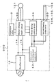
- FIG. 8 depicts a general block diagram of the second embodiment of the present invention.
- the same elements as those in FIG. 1 are denoted by the same reference numerals and will thus not be described.
- a control apparatus 500 in FIG. 8 is different from the control apparatus in FIG. 1 in that, in the former case, the direct current between the power supply lines 1a and 1b is supplied to the magnetic bearing control circuit 50, whereas, in the latter case, a DC voltage reduced down to 40 to 60 V by the direct-current stabilizing power supply circuit 40 is supplied to the magnetic bearing control circuit 50.
- One direct-current stabilizing power supply circuit 40 can be branched into a circuit for control and a circuit for a magnetic bearing. However, the direct-current stabilizing power supply circuit 40 has a larger capacity in the second embodiment than in the first embodiment.
Landscapes
- Engineering & Computer Science (AREA)
- General Engineering & Computer Science (AREA)
- Mechanical Engineering (AREA)
- Power Engineering (AREA)
- Physics & Mathematics (AREA)
- Electromagnetism (AREA)
- Magnetic Bearings And Hydrostatic Bearings (AREA)
- Non-Positive Displacement Air Blowers (AREA)
- Control Of Electric Motors In General (AREA)
Abstract
Description
- The present invention relates to an electromagnetic rotating apparatus and a vacuum pump having the electromagnetic rotating apparatus, and in particular, to an electromagnetic rotating apparatus and a vacuum pump having the electromagnetic rotating apparatus in which power generated during regeneration is consumed by an electromagnet winding in the electromagnetic rotating apparatus to allow a reduction in the size of the apparatus and in costs.
- With recent development of electronics, demands for semiconductors such as memories and integrated circuits have been growing rapidly. These semiconductors are manufactured, for example, by doping impurities into a semiconductor substrate with an extremely high purity to provide the semiconductor substrate with electric properties or forming and laminating fine circuit patterns on the semiconductor substrate. These operations need to be performed in a chamber in a vacuum sate in order to avoid the adverse effects of dust in the air or the like. To ventilate the chamber, a vacuum pump is generally used as a pump apparatus. In particular, a turbo-molecular pump - one type of vacuum pump - is frequency used because of, for example, a lower level of residual gas and high maintainability thereof.
- Furthermore, steps of manufacturing a semiconductor include a large number of steps for allowing various process gases to act on a semiconductor substrate. The turbo-molecular pump is used not only to vacuumize the inside of the chamber but also to discharge the process gases from the inside of the chamber. Moreover, the turbo-molecular pump is used in a facility for an electronic microscope or the like to set the environment in a chamber for the electronic microscope or the like to a high vacuum state in order to prevent refraction of electron beams and the like caused by the presence of dust and the like.
- Such a turbo-molecular pump includes a turbo-molecular pump main body that allows the gas to be sucked and discharged from the chamber for a semiconductor manufacturing apparatus, an electronic microscope, or the like and a control apparatus that controls the turbo-molecular pump main body.
FIG. 9 depicts a longitudinal cross-sectional view of the turbo-molecular pump main body. - In
FIG. 9 , in a turbo-molecular pump 100, aninlet port 101 is formed at an upper end of a tubularouter cylinder 127. Inside theouter cylinder 127, arotor 103 is provided which includes a plurality of rotor blades 102a, 102b, 102c, ... radially formed around a peripheral portion of the rotor at multiple stages, the rotor blades 102a, 102b, 102c, ... being turbine blades allowing the gas to be sucked and discharged. Arotor shaft 113 is attached to the center of therotor 103. Therotor shaft 113 is supported so as to float in the air and subjected to position control, for example, by a magnetic bearing for five-axis control. - In an upper
radial electromagnet 104, four electromagnets are arranged such that the electromagnets of each of two pairs of electromagnets are arranged on an X axis and a Y axis and such that the electromagnets of each of different two pairs of electromagnets are arranged in a positive direction and in a negative direction (although not depicted in the drawings, the electromagnets are denoted by 104X+, 104X-, 104Y+, and 104Y-). An upperradial sensor 107 including four electromagnets is provided in proximity to and in association with the upperradial electromagnet 104. The upperradial sensor 107 is configured to detect radial displacement of therotor 103 to transmit the relevant signal to the control apparatus. - In the control apparatus, based on a displacement signal detected by the upper
radial sensor 107, a magnetic bearing control circuit excites and controls the upperradial electromagnet 104 via a compensation circuit with a PID adjustment function to adjust an upper radial position of therotor shaft 113. Therotor shaft 113 is formed of a high-magnetic-permeability material (iron or the like) and attracted by a magnetic force of the upperradial electromagnet 104. Such adjustment is made independently in the direction of the X axis and in the direction of the Y axis. - Furthermore, a lower
radial electromagnet 105 and a lowerradial sensor 108 are arranged similarly to the upperradial electromagnet 104 and the upperradial sensor 107 to adjust a lower radial position of therotor shaft 113 similarly to the upper radial position (for the lowerradial electromagnet 105, the electromagnets are denoted by 105X+, 105X-, 105Y+, and 105Y- as needed). - Moreover, axial electromagnets 106A and 106B are arranged above and below a disc-
shaped metal disc 111 to sandwich the same that is provided below therotor shaft 113. Themetal disc 111 is formed of a high-magnetic-permeability material such as iron. Anaxial sensor 109 is provided to detect axial displacement of therotor shaft 113 so that an axial displacement signal is transmitted to the control apparatus. - Based on this axial displacement signal, the axial electromagnets 106A and 106B are excited and controlled by the magnetic bearing control circuit via the compensation circuit with the PID adjustment function, the magnetic bearing control circuit and the compensation circuit being included in the control apparatus. The axial electromagnet 106A magnetically attracts the
metal disc 111 upward. The axial electromagnet 106B magnetically attracts themetal disc 111 downward. - Thus, the control apparatus appropriately adjusts the magnetic force applied to the
metal disc 111 by the axial electromagnets 106A and 106B to allow therotor shaft 113 to magnetically float in the axial direction, thus holding therotor shaft 113 in the space in a non-contact manner. The magnetic bearing control circuit exciting and driving the upperradial electromagnet 104, the lowerradial electromagnet 105, and the axial electromagnets 106A and 106B will be described below. - On the other hand, a
motor 121 includes a plurality of magnetic poles peripherally arranged so as to surround therotor shaft 113. Each of the magnetic poles is controlled by the control apparatus so as to rotationally drive therotor shaft 113 via an electromagnetic force acting between the magnetic pole and therotor shaft 113. - Furthermore, a number-of-rotations sensor not depicted in the drawings is incorporated in the
motor 121. The number of rotations of therotor shaft 113 is detected based on a detection signal from the number-of-rotations sensor. Moreover, a phase sensor not depicted in the drawings is attached, for example, near the lowerradial sensor 108 to detect the phase of rotation of therotor shaft 113. The control apparatus uses detection signals from both the phase sensor and the number-of-rotations sensor to detect the positions of the magnetic poles. - A plurality of stator blades 123a, 123b, 123c, ... is disposed such that a small void is present between each of the stator blades 123a, 123b, 123c, ... and a corresponding one of the rotor blades 102a, 102b, 102c, ... The rotor blades 102a, 102b, 102c, ... are formed to incline at a predetermined angle to a plane perpendicular to the axis of the
rotor shaft 113 so as to transfer molecules of exhaust gas downward which collide against the rotor blades 102a, 102b, 102c, ... The stator blade 123 is also formed to incline at the predetermined angle from the plane perpendicular to the axis of therotor shaft 113 and disposed so as to extend to the center of theouter cylinder 127 and so that stages of the stator blade 123 alternate with corresponding stages of therotor blade 102. - One end of the stator blade 123 is supported so as to be fitted and inserted between a plurality of stacked stator blade spacers 125a, 125b, 125c, ... The
stator blade spacer 125 is a ring-shaped member and is formed of metal, for example, aluminum, iron, stainless steel, or copper, or an alloy containing any of these metals as a component. - The
outer cylinder 127 is fixed around an outer periphery of thestator blade spacer 125 with a small void between theouter cylinder 127 and thestator blade spacer 125. Abase portion 129 is disposed at a bottom portion of theouter cylinder 127. A threadedspacer 131 is disposed between a lower portion of thestator blade spacer 125 and thebase portion 129. Anoutlet port 133 is formed in thebase portion 129 and below the threadedspacer 131 so as to communicate with the exterior of the apparatus. - In such a configuration, when the
rotor blade 102 is driven by themotor 121 to rotate with therotor shaft 113, therotor blade 102 and the stator blade 123 act to suck exhaust gas from the chamber through theinlet port 101. - The turbo-molecular pump needs control based on individually adjusted specific parameters (for example, the identity of a machine type and characteristics corresponding to the machine type). To store the control parameters, the turbo-molecular pump
main body 100 includes anelectronic circuit section 141. Theelectronic circuit section 141 is housed near the center of thebase portion 129, which provides a lower portion of the turbo-molecular pumpmain body 100, and below the number-of-rotations sensor not depicted in the drawings. Theelectronic circuit section 141 is closed by an air-tight bottom cover 145. - Now, the control apparatus will be described. In a
control apparatus 300, arectifier circuit 10 converts an alternating current into a direct current as depicted inFIG. 10 . The direct current is converted into three phases by a motor drivingmain circuit 30 based on a pulse signal adjusted by a motordriving control circuit 20 so that themotor 121 is driven by the converted current. - Power from a
rectifier circuit 10 is reduced in voltage by a direct-current stabilizingpower supply circuit 40 and then supplied to the motordriving control circuit 20 and to the magneticbearing control circuit 50. The magneticbearing control circuit 50 passes an excitation current to each of the electromagnets including the upperradial electromagnet 104, the lowerradial electromagnet 105, and the axial electromagnets 106A and 106B. - The excitation current is passed to the pair of electromagnets providing each of the following: the upper
radial electromagnet 104, the lowerradial electromagnet 105, and the axial electromagnets 106A and 106B, as a constant steady current (bias current) on which a displacement current dependent on a position deviation signal is superimposed. - Now, the motor driving
main circuit 30 will be described. As depicted inFIG. 11 , aresistor 3 and atransistor 5 located between twopower supply lines - Furthermore,
transistors power supply lines power supply lines motor 121. Diodes 19a to 19g for passage of a regeneration current are each connected between a source and a drain of a corresponding one of thetransistors 5 to 17. - A current flowing through the
transistors transistors - In such a configuration, the
resistor 3 functions as a regeneration resistor to convert regenerated electric power generated by themotor 121 when therotor 103 is decelerated, into heat for consumption. Japanese Patent Application Laid-open Nos.H7-279962 2002-180990 2004-112877 - When the regeneration resistor is installed in the motor driving main circuit as in the conventional technique, an attachment space is needed through which the heat resulting from the regeneration resistor is transferred. This disadvantageously leads to an increase in the size of the control apparatus. Furthermore, in association with the regeneration resistor, a transistor and a diode that turn on and off a current to the regeneration resistor are needed, resulting in increased costs.
- The present invention has been developed in view of the conventional problems described above. An object of the present invention is to provide an electromagnetic rotating apparatus and a vacuum pump having the electromagnetic rotating apparatus in which power generated during regeneration is consumed by an electromagnet winding in the electromagnetic rotating apparatus to allow a reduction in the size of the apparatus and in costs.
- Thus, an aspect of the present invention (claim 1) includes a motor; a rotor shaft that is rotationally driven by the motor; an electromagnet through which, as an excitation current, a displacement current generated in accordance with a positional deviation of the rotor shaft and superimposed on a bias current is passed; a power supply that supplies a direct current; a motor driving main circuit that supplies the direct current supplied by the power supply to the motor; a motor voltage monitoring circuit that monitors a voltage of the direct current; detection signal output means for outputting a detection signal when the voltage monitored by the motor voltage monitoring circuit reaches a predetermined value or larger; and a magnetic bearing control circuit that increases the bias current that excites the electromagnet, based on the detection signal that is output by the detection signal output means.
- When a voltage applied to the motor driving main circuit is increased by overshoot or the like following arrival at a set speed during regeneration or acceleration, the bias current in the magnetic bearing is increased to allow regenerated electric power to be consumed by an electromagnet winding in a magnetic bearing apparatus. This enables a regeneration resistor to be removed. The removal of the regeneration resistor eliminates the need for an installation space for the regeneration resistor, leading to a miniaturized control apparatus. Furthermore, a switching element that turns on and off the regeneration resistor can be made unnecessary, reducing costs.
- Additionally, as aspect of the present invention (claim 2) includes: a motor driving control circuit that controls a motor current passed through the motor in accordance with a command value; and a braking current adjusting circuit that reduces the command value for the motor current, based on the detection signal that is output by the detection signal output means.
- When the voltage increases excessively during regeneration or acceleration, an electronic element may be destroyed. Thus, the motor current is adjusted to prevent the voltage from increasing during regeneration or the like. That is, when the voltage to the motor driving main circuit increases, the command value for the motor current is reduced. A reduced current flowing through the motor decreases the voltage during regeneration or the like.
- Moreover, an aspect of the present invention (claim 3) is characterized in that the power supply supplies the magnetic bearing control circuit with a direct current of a voltage identical to a voltage supplied to the motor driving main circuit.
- When the magnetic bearing control circuit is supplied with the direct current of the voltage identical to the voltage supplied to the motor driving main circuit, a direct-current stabilizing power supply circuit that supplies the direct current to the motor driving control circuit and the magnetic bearing control circuit can be reduced in size.
- Moreover, an aspect of the present invention (claim 4) is a vacuum pump including the electromagnetic rotating apparatus set forth in any one of
claims 1 to 3, characterized in that a rotor blade is attached to the rotor shaft. - As described above, according to the aspect of the present invention (claim 1), when the voltage monitored by the motor voltage monitoring circuit reaches the predetermined value or larger, the detection signal is output, and based on the detection signal, the bias current, which excites the electromagnets, is increased. Thus, when the voltage applied to the motor driving main circuit increases during regeneration, acceleration, or the like, the electromagnet winding in the magnetic bearing apparatus is allowed to consume regenerated electric power. This enables the regeneration resistor to be removed.
- The removal of the regeneration resistor eliminates the need for an installation space for the regeneration resistor, leading to a miniaturized control apparatus. Furthermore, the switching element that turns on and off the regeneration resistor can be made unnecessary, reducing costs.
-
FIG. 1 is a general block diagram of a first embodiment of the present invention; -
FIG. 2 is a control block diagram for a braking current for a motor; -
FIG. 3 is a configuration diagram of a magnetic bearing control circuit; -
FIG. 4 is a control block diagram for a current passed through an electromagnet winding; -
FIG. 5 is a system diagram for control of a radial position; -
FIG. 6 is a time chart; -
FIG. 7 is a diagram indicating how regenerated electric power is generated during acceleration; -
FIG. 8 is a general block diagram of a second embodiment of the present invention; -
FIG. 9 is a longitudinal cross-sectional view of a turbo-molecular pump main body; -
FIG. 10 is a general block diagram of a conventional technique; and -
FIG. 11 is a configuration diagram of a motor driving main circuit. - Embodiments of the present invention will be described below.
FIG. 1 depicts a general block diagram of a first embodiment of the present invention. Elements of the first embodiment which are identical to the corresponding elements inFIG. 10 are denoted by identical reference numerals and will not be described below. -
FIG. 1 depicts that an AC power supply is connected to arectifier circuit 10 in acontrol apparatus 400. Therectifier circuit 10 rectifies and converts an alternating current into a direct current of 100 to 150 V. The direct current flows betweenpower supply lines main circuit 30. Between thepower supply lines voltage monitoring circuit 60 is disposed to monitor a voltage at the motor drivingmain circuit 30. - The motor
voltage monitoring circuit 60 detects that the voltage between thepower supply lines motor 121. - At this time, the motor
voltage monitoring circuit 60 outputs a high-voltage detection signal. The high-voltage detection signal is input to a brakingcurrent adjusting circuit 70 and a magneticbearing control circuit 50. When the high-voltage detection signal is input to the brakingcurrent adjusting circuit 70, a braking current commandvalue calculating section 71 depicted inFIG. 2 calculates a command value for a braking current for themotor 121. - A
deviation section 75 determines a deviation of the command value for the braking current calculated by the braking current commandvalue calculating section 71 from a current value detected by a current detectingsection 73 disposed in series withtransistors PWM control section 77 based on the deviation. - The PWM control signal is input to a gate of each of the
transistors main circuit 30 to adjust the braking current. - A direct current that is output by the
rectifier circuit 10 is reduced to approximately several V by a direct-current stabilizingpower supply circuit 40. The resultant direct current is input to the motor drivingcontrol circuit 20 and the magneticbearing control circuit 50 as a control voltage. Furthermore, the voltage between thepower supply lines bearing control circuit 50. -
FIG. 3 is a configuration diagram of the magneticbearing control circuit 50. The magneticbearing control circuit 50 includes anamplifier circuit 250 and anamplifier control circuit 271. The control voltage from the direct-current stabilizingpower supply circuit 40 is input to theamplifier control circuit 271. -
FIG. 3 depicts that the turbo-molecular pumpmain body 100 is provided with a node common to electromagnet windings 151 providingelectromagnets transistor 261 and adiode 265 in theamplifier circuit 250 at theother end 151b of the winding (a node at theother end 151b is hereinafter referred to as a node E). - In this regard, the
transistor 261 is a power MOSFET with adrain terminal 261a connected to theother end 151b of the electromagnet winding 151 and a source terminal 261b connected anegative pole 1b of therectifier circuit 10 via a current detectingcircuit 255. Furthermore, thediode 265 is a diode for current regeneration or a flywheel including acathode terminal 265a connected to apositive pole 1a of therectifier circuit 10 and ananode terminal 265b connected to theother end 151b of the electromagnet winding 151. - The current detecting
circuit 255 connected to the source terminal 261b of thetransistor 261 has adetection resistor 256 connected to thenegative pole 1b at one end of the resistor and to the source terminal 261b of thetransistor 261 at the other end of the resistor, and adetection section 257 that detects an electromagnet current iL in a voltage at the other end of thedetection resistor 256. Thedetection section 257 detects the electromagnet current iL flowing through the electromagnet winding 151 to output acurrent detection signal 273 corresponding to a result of the detection to theamplifier control circuit 271. - The
amplifier circuit 250 configured as described above is provided for each of the electromagnet windings 151 providing theelectromagnets - The
amplifier control circuit 271 is a circuit in a DSP section (not depicted in the drawings). The high-voltage detection signal detected by the motorvoltage monitoring circuit 60 is input to theamplifier control circuit 271 as depicted inFIG. 4 . When the high-voltage detection signal is input to theamplifier control circuit 271, a current command value calculating section 371 calculates a command value for a bias current passed through the electromagnet winding 151. - A bias
current command value 373 resulting from the calculation by the current command value calculating section 371 is input to adeviation section 375 after being added in anaddition section 387 to one of two signals output by acompensation circuit 379, in order to drive an electromagnet 105X+ providing a lowerradial electromagnet 105, as depicted inFIG. 4 and a system diagram for control of a radial position inFIG. 5 . - Furthermore, to drive an
electromagnet 105X-, the other signal that is output by thecompensation circuit 379 is inverted by aninversion circuit 381, and the resultant signal is input to thedeviation section 375 after being added in theaddition section 389 to the biascurrent command value 373. - The addition of the bias current command value is intended to linearly perform radial positional control on a
rotor 103. That is, a constant direct bias current and a braking current allowing therotor 103 to be held in position are passed through the electromagnet 105X+ and theelectromagnet 105X- in a superimposed manner. - The
compensation circuit 379 receives, for example, a deviation, from aposition command value 385, of the radial position of therotor 103 detected by a position detecting circuit 383 in a lowerradial sensor 108, which deviation has been calculated by a deviation section 341. -
FIG. 4 depicts that thedeviation section 375 compares a value for the electromagnet current iL detected by the current detectingcircuit 255 with a current command value and that aPWM control section 377 determines a time for which the electromagnet current iL is increased (increase time Tp1 described below) and a time for which the electromagnet current iL is reduced (reduction time Tp2 described below), and based on these times, determines a pulse width time for agate driving signal 274 output to a gate terminal of thetransistor 261 within a control cycle Ts that is one period according to PWM control. - Moreover,
FIG. 3 depicts that aswitching circuit 280 is connected to the common node C in theamplifier circuit 250. In theswitching circuit 280, atransistor 281 and adiode 285 are connected to the common node C. - The
diode 285 is a diode for current regeneration or a flywheel including acathode terminal 285a connected to the common node C and ananode terminal 285b connected to thenegative pole 1b as is the case with theamplifier circuit 250. Furthermore, thetransistor 281 is a power MOSFET including adrain terminal 281a connected to thepositive pole 1a of therectifier circuit 10 and a source terminal 281b connected to the common node C. - A
switching signal 276 from theamplifier control circuit 271 is output to a gate terminal of thetransistor 281. Theamplifier control circuit 271 determines a pulse width time for theswitching signal 276 output to the gate terminal of thetransistor 281 within the control cycle Ts as is the case with the control performed on theamplifier circuit 250. - In such a configuration, when the
transistor 261 in theamplifier circuit 250 is turned on and thetransistor 281 in theswitching circuit 280 is turned on, a current flows from thepositive pole 1a thetransistor 281 through the common node C, the electromagnet winding 151, and the transistor 261 (and the current detecting circuit 255) to thenegative pole 1b. Consequently, the current from thepositive pole 1a is supplied to the electromagnet winding 151, thus increasing the electromagnet current iL (this state is hereinafter referred to as an increase mode A1). - On the other hand, when the
transistor 261 in theamplifier circuit 250 is turned off and thetransistor 281 in theswitching circuit 280 is turned off, a counter electromotive force is generated in the electromagnet winding 151 to pass regenerated electric power from thenegative pole 1b through thediode 285, the common node C, the electromagnet winding 151, and thediode 265 to thepositive pole 1a. Thus, electromagnetic energy generated by the electromagnet winding 151 is consumed to reduce the electromagnet current iL (this state is hereinafter referred to as a reduction mode A2). - Moreover, when the
transistor 261 in theamplifier circuit 250 is turned on and thetransistor 281 in theswitching circuit 280 is turned off, a counter electromotive force is generated in the electromagnet winding 151 to pass a flywheel current from thenegative pole 1b through thediode 285, the common node C, the electromagnet winding 151, and the transistor 261 (and the current detecting circuit 255) to thenegative pole 1b. At this time, no potential difference occurs between the opposite ends 151a and 151b of the electromagnet winding 151, thus maintaining the electromagnet current iL approximately constant (this state is hereinafter referred to as a constant mode A3). - Also in a state other than a state of the constant mode A3, when the
transistor 261 in theamplifier circuit 250 is turned off and thetransistor 281 in theswitching circuit 280 is turned on, a counter electromotive force is generated in the electromagnet winding 151 to pass a flywheel current from thepositive pole 1a through thetransistor 281, the common node C, the electromagnet winding 151, and thediode 265 to thepositive pole 1a. Thus, also in this case, the electromagnet current iL is maintained approximately constant (this state is hereinafter referred to as a constant mode A4) . -
FIG. 6 depicts a time chart illustrating adjustment of a control phase provided to thetransistor 261 and the like by theamplifier circuit 250 and a switching phase provided to thetransistor 281 and the like by the switchingcircuit 280. -
FIG. 6 depicts that theswitching circuit 280 is controlled such that, during the control cycle Ts, the time during which thetransistor 281 is on is the same as the time during which thetransistor 281 is off. In this case, thetransistor 281 is on from a point in time corresponding to the beginning of the control cycle Ts (time 0) until a point in time corresponding to the half of the control cycle Ts (time 0.5Ts). - Thus, a voltage at the common node C is substantially the same as a voltage at the
negative pole 1b due to, for example, the counter electromotive force generated in the electromagnet winding 151 (this voltage is hereinafter referred to as a voltage VL). On the other hand, thetransistor 281 is on from a point in time corresponding to the half of the control cycle Ts (time 0.5Ts) until a point in time corresponding to the end of the control cycle Ts (time Ts). Consequently, the voltage at the common node C is substantially the same as a voltage at thepositive pole 1a (this voltage is hereinafter referred to as a voltage VH). - When the value for the electromagnet current iL detected by the current detecting
circuit 255 is smaller than the current command value, theamplifier control circuit 271 performs control such that the electromagnet current iL is increased. In this case, control is performed such that, during one control cycle Ts, a state of the increase mode A1 lasts for the above-described increase time Tp1 and a state of one of the constant modes A3 and A4 lasts for the remaining time. - Specifically, the
transistor 281 in theswitching circuit 280 is on from the time 0.5Ts until the time Ts, and thus, thetransistor 261 is on for the time Tp1 beginning at the time 0.5Ts to allow the state of the increase mode A1 to last for the increase time Tp1. Furthermore, when the time Tp1 elapses, thetransistor 261 is turned off to establish the state of the constant mode A4. - On the other hand, from the
time 0 until the time 0.5Ts, thetransistor 281 in theswitching circuit 280 is off (that is, the state of the increase mode A1 cannot be established). Consequently, thetransistor 261 is turned on to establish the constant mode A3. Thus, during one control cycle Ts, the electromagnet current iL is increased for the increase time Tp1. - On the other hand, when the value for the electromagnet current iL detected by the current detecting
circuit 255 is larger than the current command value, theamplifier control circuit 271 performs control such that the electromagnet current iL is reduced. In this case, control is performed such that, during one control cycle Ts, the state of the reduction mode A2 lasts for the above-described reduction time Tp2 and the state of one of the constant modes A3 and A4 lasts for the remaining time. - Specifically, the
transistor 281 in theswitching circuit 280 is off from thetime 0 until the time 0.5Ts, and thus, thetransistor 261 is off for the time Tp2 ending at the time 0.5Ts to allow the state of the reduction mode A2 to last for the reduction time Tp2. Furthermore, before thetransistor 261 is turned off, thetransistor 261 is kept on to maintain the state of the constant mode A3. - On the other hand, from the time 0.5Ts until the time Ts, the
transistor 281 in theswitching circuit 280 is on (that is, the state of the reduction mode A2 cannot be established). Consequently, thetransistor 261 is turned off to establish the constant mode A4. Thus, during one control cycle Ts, the electromagnet current iL is reduced for the reduction time Tp2. - Moreover, when the value for the electromagnet current iL detected by the current detecting
circuit 255 matches with the current command value, theamplifier control circuit 271 performs control such that the electromagnet current iL is maintained constant. In this case, control is performed such that one of the constant modes A3 and A4 is constantly present during one control cycle Ts. - Specifically, from the
time 0 until the time 0.5Ts, thetransistor 281 in theswitching circuit 280 is off, and thus, thetransistor 261 is turned on to establish the state of the constant mode A3. - On the other hand, from the time 0.5Ts until the time Ts, the
transistor 281 in theswitching circuit 280 is on, and thus, thetransistor 261 is turned off to establish the state of the constant mode A4. Thus, the electromagnet current iL is maintained at a predetermined level. - As described above, the electromagnet current iL can be increased or reduced or maintained constant so as to be equal to the current command value, by controlling the
amplifier circuit 250 while controlling theswitching circuit 280. - Now, operations of the first embodiment will be described. In
FIG. 1 , unlike inFIG. 10 , theregeneration resistor 3 and thetransistor 5 are omitted from the motor drivingmain circuit 30. Regenerated electric power consumed by theregeneration resistor 3 according to the conventional technique is consumed by the electromagnet winding 151. - When the energy consumed by the electromagnet winding 151 is not equal to all of the energy consumed by the
regeneration resistor 3 according to the conventional technique, then without theregeneration resistor 3, the voltage at the motor drivingmain circuit 30 increases when a regenerative current flows at the time of overshoot following arrival at a set rotation speed during deceleration of themotor 121 or during acceleration themotor 121 as depicted inFIG. 7 . When the voltage thus increases, an electronic element may be broken. Consequently, an increase in voltage needs to be prevented by adjusting the braking current. - Thus, when the voltage at the motor driving
main circuit 30 becomes at least 10 to 20% higher during deceleration or acceleration of themotor 121 than during normal operation, the motorvoltage monitoring circuit 60 detects this state and transmits a high-voltage detection signal to the brakingcurrent adjusting circuit 70 and the magneticbearing control circuit 50. - Upon receiving the high-voltage detection signal, the braking
current adjusting circuit 70 reduces a braking current command value for themotor 121 so as to maintain the excitation voltage constant or reduce the excitation voltage. A deviation, from the braking current command value, of a current flowing throughtransistors transistors motor 121 decreases, and the reduced braking current lowers regenerated electric power generated betweenpower supply lines - On the other hand, upon receiving the high-voltage detection signal, the
amplifier control circuit 271 in the magneticbearing control circuit 50 calculates a current command value including a bias current so as to increase the current flowing through the electromagnet winding 151 by a factor of approximately 1.2 to 3 compared to the bias current during the normal operation. That is, when the voltage at the motor drivingmain circuit 30 increases, the current including the bias current and flowing through the electromagnet winding 151 is increased, thereby increasing power consumption. - As described above, even when the
regeneration resistor 3 is removed, the regenerated electric power may be consumed and the pump may be stably stopped. Furthermore, the removal of theregeneration resistor 3 eliminates the need for an installation space for the regeneration resistor, leading to the size reduction of a control apparatus. Additionally, a switching element that turns on and off theregeneration resistor 3 can be made unnecessary, reducing costs. - The
regeneration resistor 3 is removed in the above description but may be left. In this case, the electromagnet winding 151 side consumes most of the regenerated energy, enabling a reduction in the capacities of theregeneration resistor 3 and the switching element that turns theregeneration resistor 3 on and off. Furthermore, the pump may be quickly stopped. - The high-voltage detection signal is represented as a reference character but may be represented as a consecutive voltage value. Alternatively, the high-voltage detection signal may be represented as a reference character generated in a step-by-step manner in accordance with the level of the voltage value. The consecutive voltage value enables the braking current and the bias current to be consecutively adjusted. The step-by-step reference character allows the adjustment of the braking current and the bias current to be changed in a step-by-step manner.
- Now, a second embodiment of the present invention will be described.
FIG. 8 depicts a general block diagram of the second embodiment of the present invention. The same elements as those inFIG. 1 are denoted by the same reference numerals and will thus not be described. - a
control apparatus 500 inFIG. 8 is different from the control apparatus inFIG. 1 in that, in the former case, the direct current between thepower supply lines bearing control circuit 50, whereas, in the latter case, a DC voltage reduced down to 40 to 60 V by the direct-current stabilizingpower supply circuit 40 is supplied to the magneticbearing control circuit 50. One direct-current stabilizingpower supply circuit 40 can be branched into a circuit for control and a circuit for a magnetic bearing. However, the direct-current stabilizingpower supply circuit 40 has a larger capacity in the second embodiment than in the first embodiment. - 1
- Power supply line
- 3
- Regeneration resistor
- 5 to 17, 261, 281
- Transistor
- 10
- Rectifier circuit
- 20
- Motor driving control circuit
- 30
- Motor driving main circuit
- 40
- Direct-current stabilizing power supply circuit
- 50
- Magnetic bearing control circuit
- 60
- Motor voltage monitoring circuit
- 70
- Braking current adjusting circuit
- 71
- Braking current command value calculating section
- 73
- Current detecting section
- 75, 375
- Deviation section
- 77, 377
- PWM control section
- 100
- Turbo-molecular pump main body
- 102
- Rotor blade
- 104
- Upper radial electromagnet
- 105
- Lower radial electromagnet
- 106A, 106B
- Axial electromagnet
- 113
- Rotor shaft
- 121
- Motor
- 151
- Electromagnet winding
- 250
- Amplifier circuit
- 255
- Current detecting circuit
- 256
- Detection resistor
- 257
- Detection section
- 265, 285
- Diode
- 271
- Amplifier control circuit
- 273
- Current detection signal
- 274
- Gate driving signal
- 276
- Switching signal
- 280
- Switching circuit
- 300, 400, 500
- Control apparatus
- 371
- Current command value calculating section
- 373
- Bias current command value
Claims (4)
- An electromagnetic rotating apparatus comprising: a motor; a rotor shaft that is rotationally driven by the motor; an electromagnet through which, as an excitation current, a displacement current generated in accordance with a positional deviation of the rotor shaft and superimposed on a bias current is passed; a power supply that supplies a direct current; a motor driving main circuit that supplies the direct current supplied by the power supply to the motor; a motor voltage monitoring circuit that monitors a voltage of the direct current; detection signal output means for outputting a detection signal when the voltage monitored by the motor voltage monitoring circuit reaches a predetermined value or larger; and a magnetic bearing control circuit that increases the bias current that excites the electromagnet, based on the detection signal that is output by the detection signal output means.
- The electromagnetic rotating apparatus according to claim 1, further comprising: a motor driving control circuit that controls a motor current passing through the motor in accordance with a command value; and a braking current adjusting circuit that reduces the command value for the motor current, based on the detection signal that is output by the detection signal output means.
- The electromagnetic rotating apparatus according to claim 1 or claim 2, wherein the power supply supplies the magnetic bearing control circuit with a direct current of a voltage identical to a voltage supplied to the motor driving main circuit.
- A vacuum pump comprising the electromagnetic rotating apparatus according to any one of claims 1 to 3, wherein a rotor blade is attached to the rotor shaft.
Applications Claiming Priority (2)
| Application Number | Priority Date | Filing Date | Title |
|---|---|---|---|
| JP2012262591A JP6077286B2 (en) | 2012-11-30 | 2012-11-30 | Electromagnetic rotating device and vacuum pump provided with the electromagnetic rotating device |
| PCT/JP2013/077510 WO2014083946A1 (en) | 2012-11-30 | 2013-10-09 | Electromagnetic rotating device and vacuum pump equipped with electromagnetic rotating device |
Publications (3)
| Publication Number | Publication Date |
|---|---|
| EP2928073A1 true EP2928073A1 (en) | 2015-10-07 |
| EP2928073A4 EP2928073A4 (en) | 2016-07-06 |
| EP2928073B1 EP2928073B1 (en) | 2017-06-21 |
Family
ID=50827592
Family Applications (1)
| Application Number | Title | Priority Date | Filing Date |
|---|---|---|---|
| EP13857910.7A Active EP2928073B1 (en) | 2012-11-30 | 2013-10-09 | Electromagnetic rotating device and vacuum pump equipped with electromagnetic rotating device |
Country Status (6)
| Country | Link |
|---|---|
| US (1) | US10876540B2 (en) |
| EP (1) | EP2928073B1 (en) |
| JP (1) | JP6077286B2 (en) |
| KR (1) | KR102106659B1 (en) |
| CN (1) | CN104782045B (en) |
| WO (1) | WO2014083946A1 (en) |
Cited By (2)
| Publication number | Priority date | Publication date | Assignee | Title |
|---|---|---|---|---|
| EP3677785A4 (en) * | 2017-08-31 | 2021-05-26 | Edwards Japan Limited | VACUUM PUMP AND CONTROL DEVICE |
| EP2988009B1 (en) * | 2013-04-16 | 2021-09-01 | Edwards Japan Limited | Magnetic bearing device, and vacuum pump provided with said magnetic bearing device |
Families Citing this family (6)
| Publication number | Priority date | Publication date | Assignee | Title |
|---|---|---|---|---|
| CN105071735B (en) * | 2015-07-31 | 2017-08-22 | 西安理工大学 | Asynchronous machine energy-saving control method based on the simplified models of T 1 |
| CN105446231A (en) * | 2015-12-29 | 2016-03-30 | 安徽海兴泰瑞智能科技有限公司 | Pumping station energy consumption analysis and monitoring system |
| CN106549362A (en) * | 2016-10-31 | 2017-03-29 | 青岛海尔科技有限公司 | A kind of motor and motor protection method |
| JP6967954B2 (en) * | 2017-12-05 | 2021-11-17 | 東京エレクトロン株式会社 | Exhaust device, processing device and exhaust method |
| TWI654376B (en) | 2018-04-17 | 2019-03-21 | 太琦科技股份有限公司 | Pump control system and its operation method |
| CN110107593B (en) * | 2019-04-19 | 2020-06-02 | 微控物理储能研究开发(深圳)有限公司 | Non-biased magnetic bearing coil control circuit and control method |
Family Cites Families (16)
| Publication number | Priority date | Publication date | Assignee | Title |
|---|---|---|---|---|
| JPH04271288A (en) * | 1991-02-25 | 1992-09-28 | Mitsubishi Electric Corp | Control method for inverter group |
| JP3585950B2 (en) | 1994-04-13 | 2004-11-10 | Bocエドワーズ株式会社 | Magnetic bearing type rotating device |
| JP3793856B2 (en) * | 1996-08-01 | 2006-07-05 | 株式会社ジェイテクト | Magnetic bearing device |
| JP3550465B2 (en) * | 1996-08-30 | 2004-08-04 | 株式会社日立製作所 | Turbo vacuum pump and operating method thereof |
| JP2000145774A (en) * | 1998-11-17 | 2000-05-26 | Koyo Seiko Co Ltd | Control-type magnetic bearing device |
| JP2001086704A (en) * | 1999-09-13 | 2001-03-30 | Ebara Corp | Magnetic bearing device with integrated motor structure |
| JP4249916B2 (en) * | 2000-09-18 | 2009-04-08 | エドワーズ株式会社 | Brushless motor control circuit, brushless motor device, and vacuum pump device |
| JP2002180990A (en) | 2000-12-11 | 2002-06-26 | Ebara Corp | Vacuum pump controller |
| JP4674422B2 (en) * | 2001-07-17 | 2011-04-20 | 株式会社島津製作所 | Apparatus and pump system with multiple turbomolecular pumps |
| JP3772979B2 (en) | 2002-09-13 | 2006-05-10 | 株式会社荏原製作所 | Braking control device for rotating machine |
| US20050174087A1 (en) * | 2004-02-10 | 2005-08-11 | Koyo Seiko Co., Ltd. | Control magnetic bearing device |
| JP4031398B2 (en) * | 2003-07-04 | 2008-01-09 | 住友重機械工業株式会社 | Molding machine |
| JP2005198377A (en) | 2004-01-05 | 2005-07-21 | Matsushita Electric Ind Co Ltd | Inverter controller for motor drive |
| JP2005198441A (en) * | 2004-01-08 | 2005-07-21 | Tamagawa Seiki Co Ltd | Control method of brushless motor |
| JP4502667B2 (en) | 2004-03-04 | 2010-07-14 | エドワーズ株式会社 | Magnetic bearing device and turbomolecular pump equipped with the magnetic bearing device |
| US20080206079A1 (en) * | 2007-02-27 | 2008-08-28 | Jtekt Corporation | Turbo-molecular pump and touchdown bearing device |
-
2012
- 2012-11-30 JP JP2012262591A patent/JP6077286B2/en active Active
-
2013
- 2013-10-09 KR KR1020157006203A patent/KR102106659B1/en active Active
- 2013-10-09 WO PCT/JP2013/077510 patent/WO2014083946A1/en not_active Ceased
- 2013-10-09 CN CN201380061136.7A patent/CN104782045B/en active Active
- 2013-10-09 US US14/443,102 patent/US10876540B2/en active Active
- 2013-10-09 EP EP13857910.7A patent/EP2928073B1/en active Active
Cited By (2)
| Publication number | Priority date | Publication date | Assignee | Title |
|---|---|---|---|---|
| EP2988009B1 (en) * | 2013-04-16 | 2021-09-01 | Edwards Japan Limited | Magnetic bearing device, and vacuum pump provided with said magnetic bearing device |
| EP3677785A4 (en) * | 2017-08-31 | 2021-05-26 | Edwards Japan Limited | VACUUM PUMP AND CONTROL DEVICE |
Also Published As
| Publication number | Publication date |
|---|---|
| CN104782045B (en) | 2017-10-10 |
| KR20150088992A (en) | 2015-08-04 |
| US20150303836A1 (en) | 2015-10-22 |
| US10876540B2 (en) | 2020-12-29 |
| KR102106659B1 (en) | 2020-05-04 |
| JP6077286B2 (en) | 2017-02-08 |
| JP2014110653A (en) | 2014-06-12 |
| EP2928073A4 (en) | 2016-07-06 |
| WO2014083946A1 (en) | 2014-06-05 |
| EP2928073B1 (en) | 2017-06-21 |
| CN104782045A (en) | 2015-07-15 |
Similar Documents
| Publication | Publication Date | Title |
|---|---|---|
| EP2928073B1 (en) | Electromagnetic rotating device and vacuum pump equipped with electromagnetic rotating device | |
| EP2315349B1 (en) | Motor driver circuit and vacuum pump equipped with motor driver circuit | |
| EP1460293B1 (en) | Magnetic bearing device and pump device with the magnetic bearing device mounted thereto | |
| CN100446416C (en) | Magnetic bearing device and turbomolecular pump equipped with the magnetic bearing device | |
| KR102589086B1 (en) | Vacuum pump and control unit | |
| KR20040082954A (en) | Magnetic bearing device and turbo molecular pump with the magnetic bearing device mounted thereto | |
| JP2005083316A (en) | Motor control system and vacuum pump mounting the same | |
| JP2013253502A (en) | Vacuum pump | |
| JP4376645B2 (en) | Magnetic bearing device and turbomolecular pump equipped with the magnetic bearing device | |
| US12305652B2 (en) | Vacuum pump | |
| JP2005094852A (en) | Motor control system and vacuum pump mounting same thereon |
Legal Events
| Date | Code | Title | Description |
|---|---|---|---|
| PUAI | Public reference made under article 153(3) epc to a published international application that has entered the european phase |
Free format text: ORIGINAL CODE: 0009012 |
|
| 17P | Request for examination filed |
Effective date: 20150513 |
|
| AK | Designated contracting states |
Kind code of ref document: A1 Designated state(s): AL AT BE BG CH CY CZ DE DK EE ES FI FR GB GR HR HU IE IS IT LI LT LU LV MC MK MT NL NO PL PT RO RS SE SI SK SM TR |
|
| AX | Request for extension of the european patent |
Extension state: BA ME |
|
| DAX | Request for extension of the european patent (deleted) | ||
| RA4 | Supplementary search report drawn up and despatched (corrected) |
Effective date: 20160608 |
|
| RIC1 | Information provided on ipc code assigned before grant |
Ipc: H02P 29/00 20160101ALI20160602BHEP Ipc: F04D 19/04 20060101ALI20160602BHEP Ipc: F16C 32/04 20060101ALI20160602BHEP Ipc: H02P 29/02 20060101AFI20160602BHEP |
|
| GRAP | Despatch of communication of intention to grant a patent |
Free format text: ORIGINAL CODE: EPIDOSNIGR1 |
|
| STAA | Information on the status of an ep patent application or granted ep patent |
Free format text: STATUS: GRANT OF PATENT IS INTENDED |
|
| RIC1 | Information provided on ipc code assigned before grant |
Ipc: F04D 27/02 20060101ALI20161123BHEP Ipc: H02P 29/00 20160101ALI20161123BHEP Ipc: F04D 19/04 20060101ALI20161123BHEP Ipc: F04D 25/06 20060101ALI20161123BHEP Ipc: H02P 29/02 20060101AFI20161123BHEP Ipc: F04D 29/058 20060101ALI20161123BHEP Ipc: F16C 32/04 20060101ALI20161123BHEP |
|
| INTG | Intention to grant announced |
Effective date: 20161222 |
|
| GRAS | Grant fee paid |
Free format text: ORIGINAL CODE: EPIDOSNIGR3 |
|
| GRAJ | Information related to disapproval of communication of intention to grant by the applicant or resumption of examination proceedings by the epo deleted |
Free format text: ORIGINAL CODE: EPIDOSDIGR1 |
|
| GRAL | Information related to payment of fee for publishing/printing deleted |
Free format text: ORIGINAL CODE: EPIDOSDIGR3 |
|
| STAA | Information on the status of an ep patent application or granted ep patent |
Free format text: STATUS: REQUEST FOR EXAMINATION WAS MADE |
|
| GRAP | Despatch of communication of intention to grant a patent |
Free format text: ORIGINAL CODE: EPIDOSNIGR1 |
|
| STAA | Information on the status of an ep patent application or granted ep patent |
Free format text: STATUS: GRANT OF PATENT IS INTENDED |
|
| INTC | Intention to grant announced (deleted) | ||
| GRAA | (expected) grant |
Free format text: ORIGINAL CODE: 0009210 |
|
| STAA | Information on the status of an ep patent application or granted ep patent |
Free format text: STATUS: THE PATENT HAS BEEN GRANTED |
|
| INTG | Intention to grant announced |
Effective date: 20170428 |
|
| AK | Designated contracting states |
Kind code of ref document: B1 Designated state(s): AL AT BE BG CH CY CZ DE DK EE ES FI FR GB GR HR HU IE IS IT LI LT LU LV MC MK MT NL NO PL PT RO RS SE SI SK SM TR |
|
| REG | Reference to a national code |
Ref country code: GB Ref legal event code: FG4D |
|
| REG | Reference to a national code |
Ref country code: CH Ref legal event code: EP |
|
| REG | Reference to a national code |
Ref country code: IE Ref legal event code: FG4D |
|
| REG | Reference to a national code |
Ref country code: AT Ref legal event code: REF Ref document number: 903767 Country of ref document: AT Kind code of ref document: T Effective date: 20170715 |
|
| REG | Reference to a national code |
Ref country code: DE Ref legal event code: R096 Ref document number: 602013022707 Country of ref document: DE |
|
| REG | Reference to a national code |
Ref country code: FR Ref legal event code: PLFP Year of fee payment: 5 |
|
| REG | Reference to a national code |
Ref country code: NL Ref legal event code: MP Effective date: 20170621 |
|
| PG25 | Lapsed in a contracting state [announced via postgrant information from national office to epo] |
Ref country code: LT Free format text: LAPSE BECAUSE OF FAILURE TO SUBMIT A TRANSLATION OF THE DESCRIPTION OR TO PAY THE FEE WITHIN THE PRESCRIBED TIME-LIMIT Effective date: 20170621 Ref country code: FI Free format text: LAPSE BECAUSE OF FAILURE TO SUBMIT A TRANSLATION OF THE DESCRIPTION OR TO PAY THE FEE WITHIN THE PRESCRIBED TIME-LIMIT Effective date: 20170621 Ref country code: NO Free format text: LAPSE BECAUSE OF FAILURE TO SUBMIT A TRANSLATION OF THE DESCRIPTION OR TO PAY THE FEE WITHIN THE PRESCRIBED TIME-LIMIT Effective date: 20170921 Ref country code: GR Free format text: LAPSE BECAUSE OF FAILURE TO SUBMIT A TRANSLATION OF THE DESCRIPTION OR TO PAY THE FEE WITHIN THE PRESCRIBED TIME-LIMIT Effective date: 20170922 Ref country code: HR Free format text: LAPSE BECAUSE OF FAILURE TO SUBMIT A TRANSLATION OF THE DESCRIPTION OR TO PAY THE FEE WITHIN THE PRESCRIBED TIME-LIMIT Effective date: 20170621 |
|
| REG | Reference to a national code |
Ref country code: LT Ref legal event code: MG4D |
|
| REG | Reference to a national code |
Ref country code: AT Ref legal event code: MK05 Ref document number: 903767 Country of ref document: AT Kind code of ref document: T Effective date: 20170621 |
|
| PG25 | Lapsed in a contracting state [announced via postgrant information from national office to epo] |
Ref country code: BG Free format text: LAPSE BECAUSE OF FAILURE TO SUBMIT A TRANSLATION OF THE DESCRIPTION OR TO PAY THE FEE WITHIN THE PRESCRIBED TIME-LIMIT Effective date: 20170921 Ref country code: NL Free format text: LAPSE BECAUSE OF FAILURE TO SUBMIT A TRANSLATION OF THE DESCRIPTION OR TO PAY THE FEE WITHIN THE PRESCRIBED TIME-LIMIT Effective date: 20170621 Ref country code: RS Free format text: LAPSE BECAUSE OF FAILURE TO SUBMIT A TRANSLATION OF THE DESCRIPTION OR TO PAY THE FEE WITHIN THE PRESCRIBED TIME-LIMIT Effective date: 20170621 Ref country code: LV Free format text: LAPSE BECAUSE OF FAILURE TO SUBMIT A TRANSLATION OF THE DESCRIPTION OR TO PAY THE FEE WITHIN THE PRESCRIBED TIME-LIMIT Effective date: 20170621 Ref country code: SE Free format text: LAPSE BECAUSE OF FAILURE TO SUBMIT A TRANSLATION OF THE DESCRIPTION OR TO PAY THE FEE WITHIN THE PRESCRIBED TIME-LIMIT Effective date: 20170621 |
|
| PG25 | Lapsed in a contracting state [announced via postgrant information from national office to epo] |
Ref country code: SK Free format text: LAPSE BECAUSE OF FAILURE TO SUBMIT A TRANSLATION OF THE DESCRIPTION OR TO PAY THE FEE WITHIN THE PRESCRIBED TIME-LIMIT Effective date: 20170621 Ref country code: RO Free format text: LAPSE BECAUSE OF FAILURE TO SUBMIT A TRANSLATION OF THE DESCRIPTION OR TO PAY THE FEE WITHIN THE PRESCRIBED TIME-LIMIT Effective date: 20170621 Ref country code: EE Free format text: LAPSE BECAUSE OF FAILURE TO SUBMIT A TRANSLATION OF THE DESCRIPTION OR TO PAY THE FEE WITHIN THE PRESCRIBED TIME-LIMIT Effective date: 20170621 Ref country code: CZ Free format text: LAPSE BECAUSE OF FAILURE TO SUBMIT A TRANSLATION OF THE DESCRIPTION OR TO PAY THE FEE WITHIN THE PRESCRIBED TIME-LIMIT Effective date: 20170621 Ref country code: AT Free format text: LAPSE BECAUSE OF FAILURE TO SUBMIT A TRANSLATION OF THE DESCRIPTION OR TO PAY THE FEE WITHIN THE PRESCRIBED TIME-LIMIT Effective date: 20170621 |
|
| PG25 | Lapsed in a contracting state [announced via postgrant information from national office to epo] |
Ref country code: SM Free format text: LAPSE BECAUSE OF FAILURE TO SUBMIT A TRANSLATION OF THE DESCRIPTION OR TO PAY THE FEE WITHIN THE PRESCRIBED TIME-LIMIT Effective date: 20170621 Ref country code: ES Free format text: LAPSE BECAUSE OF FAILURE TO SUBMIT A TRANSLATION OF THE DESCRIPTION OR TO PAY THE FEE WITHIN THE PRESCRIBED TIME-LIMIT Effective date: 20170621 Ref country code: PL Free format text: LAPSE BECAUSE OF FAILURE TO SUBMIT A TRANSLATION OF THE DESCRIPTION OR TO PAY THE FEE WITHIN THE PRESCRIBED TIME-LIMIT Effective date: 20170621 Ref country code: IT Free format text: LAPSE BECAUSE OF FAILURE TO SUBMIT A TRANSLATION OF THE DESCRIPTION OR TO PAY THE FEE WITHIN THE PRESCRIBED TIME-LIMIT Effective date: 20170621 Ref country code: IS Free format text: LAPSE BECAUSE OF FAILURE TO SUBMIT A TRANSLATION OF THE DESCRIPTION OR TO PAY THE FEE WITHIN THE PRESCRIBED TIME-LIMIT Effective date: 20171021 |
|
| REG | Reference to a national code |
Ref country code: DE Ref legal event code: R097 Ref document number: 602013022707 Country of ref document: DE |
|
| PLBE | No opposition filed within time limit |
Free format text: ORIGINAL CODE: 0009261 |
|
| STAA | Information on the status of an ep patent application or granted ep patent |
Free format text: STATUS: NO OPPOSITION FILED WITHIN TIME LIMIT |
|
| PG25 | Lapsed in a contracting state [announced via postgrant information from national office to epo] |
Ref country code: DK Free format text: LAPSE BECAUSE OF FAILURE TO SUBMIT A TRANSLATION OF THE DESCRIPTION OR TO PAY THE FEE WITHIN THE PRESCRIBED TIME-LIMIT Effective date: 20170621 |
|
| 26N | No opposition filed |
Effective date: 20180322 |
|
| PG25 | Lapsed in a contracting state [announced via postgrant information from national office to epo] |
Ref country code: MC Free format text: LAPSE BECAUSE OF FAILURE TO SUBMIT A TRANSLATION OF THE DESCRIPTION OR TO PAY THE FEE WITHIN THE PRESCRIBED TIME-LIMIT Effective date: 20170621 |
|
| REG | Reference to a national code |
Ref country code: CH Ref legal event code: PL |
|
| REG | Reference to a national code |
Ref country code: IE Ref legal event code: MM4A |
|
| PG25 | Lapsed in a contracting state [announced via postgrant information from national office to epo] |
Ref country code: CH Free format text: LAPSE BECAUSE OF NON-PAYMENT OF DUE FEES Effective date: 20171031 Ref country code: LU Free format text: LAPSE BECAUSE OF NON-PAYMENT OF DUE FEES Effective date: 20171009 Ref country code: LI Free format text: LAPSE BECAUSE OF NON-PAYMENT OF DUE FEES Effective date: 20171031 |
|
| REG | Reference to a national code |
Ref country code: BE Ref legal event code: MM Effective date: 20171031 |
|
| PG25 | Lapsed in a contracting state [announced via postgrant information from national office to epo] |
Ref country code: BE Free format text: LAPSE BECAUSE OF NON-PAYMENT OF DUE FEES Effective date: 20171031 Ref country code: SI Free format text: LAPSE BECAUSE OF FAILURE TO SUBMIT A TRANSLATION OF THE DESCRIPTION OR TO PAY THE FEE WITHIN THE PRESCRIBED TIME-LIMIT Effective date: 20170621 |
|
| REG | Reference to a national code |
Ref country code: FR Ref legal event code: PLFP Year of fee payment: 6 |
|
| PG25 | Lapsed in a contracting state [announced via postgrant information from national office to epo] |
Ref country code: MT Free format text: LAPSE BECAUSE OF NON-PAYMENT OF DUE FEES Effective date: 20171009 |
|
| PG25 | Lapsed in a contracting state [announced via postgrant information from national office to epo] |
Ref country code: IE Free format text: LAPSE BECAUSE OF NON-PAYMENT OF DUE FEES Effective date: 20171009 |
|
| PG25 | Lapsed in a contracting state [announced via postgrant information from national office to epo] |
Ref country code: HU Free format text: LAPSE BECAUSE OF FAILURE TO SUBMIT A TRANSLATION OF THE DESCRIPTION OR TO PAY THE FEE WITHIN THE PRESCRIBED TIME-LIMIT; INVALID AB INITIO Effective date: 20131009 |
|
| PG25 | Lapsed in a contracting state [announced via postgrant information from national office to epo] |
Ref country code: CY Free format text: LAPSE BECAUSE OF FAILURE TO SUBMIT A TRANSLATION OF THE DESCRIPTION OR TO PAY THE FEE WITHIN THE PRESCRIBED TIME-LIMIT Effective date: 20170621 |
|
| PG25 | Lapsed in a contracting state [announced via postgrant information from national office to epo] |
Ref country code: MK Free format text: LAPSE BECAUSE OF FAILURE TO SUBMIT A TRANSLATION OF THE DESCRIPTION OR TO PAY THE FEE WITHIN THE PRESCRIBED TIME-LIMIT Effective date: 20170621 |
|
| PG25 | Lapsed in a contracting state [announced via postgrant information from national office to epo] |
Ref country code: TR Free format text: LAPSE BECAUSE OF FAILURE TO SUBMIT A TRANSLATION OF THE DESCRIPTION OR TO PAY THE FEE WITHIN THE PRESCRIBED TIME-LIMIT Effective date: 20170621 |
|
| PG25 | Lapsed in a contracting state [announced via postgrant information from national office to epo] |
Ref country code: PT Free format text: LAPSE BECAUSE OF FAILURE TO SUBMIT A TRANSLATION OF THE DESCRIPTION OR TO PAY THE FEE WITHIN THE PRESCRIBED TIME-LIMIT Effective date: 20170621 |
|
| PG25 | Lapsed in a contracting state [announced via postgrant information from national office to epo] |
Ref country code: AL Free format text: LAPSE BECAUSE OF FAILURE TO SUBMIT A TRANSLATION OF THE DESCRIPTION OR TO PAY THE FEE WITHIN THE PRESCRIBED TIME-LIMIT Effective date: 20170621 |
|
| P01 | Opt-out of the competence of the unified patent court (upc) registered |
Effective date: 20230505 |
|
| PGFP | Annual fee paid to national office [announced via postgrant information from national office to epo] |
Ref country code: DE Payment date: 20251029 Year of fee payment: 13 |
|
| PGFP | Annual fee paid to national office [announced via postgrant information from national office to epo] |
Ref country code: GB Payment date: 20251027 Year of fee payment: 13 |
|
| PGFP | Annual fee paid to national office [announced via postgrant information from national office to epo] |
Ref country code: FR Payment date: 20251027 Year of fee payment: 13 |