EP2927757A1 - Control device design method and control device - Google Patents
Control device design method and control device Download PDFInfo
- Publication number
- EP2927757A1 EP2927757A1 EP13859458.5A EP13859458A EP2927757A1 EP 2927757 A1 EP2927757 A1 EP 2927757A1 EP 13859458 A EP13859458 A EP 13859458A EP 2927757 A1 EP2927757 A1 EP 2927757A1
- Authority
- EP
- European Patent Office
- Prior art keywords
- transfer function
- feedback
- plant
- feedback controller
- control device
- Prior art date
- Legal status (The legal status is an assumption and is not a legal conclusion. Google has not performed a legal analysis and makes no representation as to the accuracy of the status listed.)
- Granted
Links
Images


Classifications
-
- G—PHYSICS
- G05—CONTROLLING; REGULATING
- G05B—CONTROL OR REGULATING SYSTEMS IN GENERAL; FUNCTIONAL ELEMENTS OF SUCH SYSTEMS; MONITORING OR TESTING ARRANGEMENTS FOR SUCH SYSTEMS OR ELEMENTS
- G05B11/00—Automatic controllers
- G05B11/01—Automatic controllers electric
- G05B11/36—Automatic controllers electric with provision for obtaining particular characteristics, e.g. proportional, integral, differential
- G05B11/42—Automatic controllers electric with provision for obtaining particular characteristics, e.g. proportional, integral, differential for obtaining a characteristic which is both proportional and time-dependent, e.g. P. I., P. I. D.
-
- G—PHYSICS
- G05—CONTROLLING; REGULATING
- G05B—CONTROL OR REGULATING SYSTEMS IN GENERAL; FUNCTIONAL ELEMENTS OF SUCH SYSTEMS; MONITORING OR TESTING ARRANGEMENTS FOR SUCH SYSTEMS OR ELEMENTS
- G05B19/00—Program-control systems
- G05B19/02—Program-control systems electric
- G05B19/18—Numerical control [NC], i.e. automatically operating machines, in particular machine tools, e.g. in a manufacturing environment, so as to execute positioning, movement or co-ordinated operations by means of program data in numerical form
- G05B19/19—Numerical control [NC], i.e. automatically operating machines, in particular machine tools, e.g. in a manufacturing environment, so as to execute positioning, movement or co-ordinated operations by means of program data in numerical form characterised by positioning or contouring control systems, e.g. to control position from one programmed point to another or to control movement along a programmed continuous path
-
- G—PHYSICS
- G05—CONTROLLING; REGULATING
- G05B—CONTROL OR REGULATING SYSTEMS IN GENERAL; FUNCTIONAL ELEMENTS OF SUCH SYSTEMS; MONITORING OR TESTING ARRANGEMENTS FOR SUCH SYSTEMS OR ELEMENTS
- G05B2219/00—Program-control systems
- G05B2219/30—Nc systems
- G05B2219/41—Servomotor, servo controller till figures
- G05B2219/41368—Disturbance observer, inject disturbance, adapt controller to resulting effect
-
- G—PHYSICS
- G05—CONTROLLING; REGULATING
- G05B—CONTROL OR REGULATING SYSTEMS IN GENERAL; FUNCTIONAL ELEMENTS OF SUCH SYSTEMS; MONITORING OR TESTING ARRANGEMENTS FOR SUCH SYSTEMS OR ELEMENTS
- G05B2219/00—Program-control systems
- G05B2219/30—Nc systems
- G05B2219/42—Servomotor, servo controller kind till VSS
- G05B2219/42033—Kind of servo controller
-
- Y—GENERAL TAGGING OF NEW TECHNOLOGICAL DEVELOPMENTS; GENERAL TAGGING OF CROSS-SECTIONAL TECHNOLOGIES SPANNING OVER SEVERAL SECTIONS OF THE IPC; TECHNICAL SUBJECTS COVERED BY FORMER USPC CROSS-REFERENCE ART COLLECTIONS [XRACs] AND DIGESTS
- Y02—TECHNOLOGIES OR APPLICATIONS FOR MITIGATION OR ADAPTATION AGAINST CLIMATE CHANGE
- Y02P—CLIMATE CHANGE MITIGATION TECHNOLOGIES IN THE PRODUCTION OR PROCESSING OF GOODS
- Y02P90/00—Enabling technologies with a potential contribution to greenhouse gas [GHG] emissions mitigation
- Y02P90/02—Total factory control, e.g. smart factories, flexible manufacturing systems [FMS] or integrated manufacturing systems [IMS]
Definitions
- the present invention relates to a design method of control device and to a control device.
- a feedback control system control device 2 is such that a feedback controller 201 outputs a manipulated variable u based on the difference between a controlled variable y of a plant 9, calculated by an adder 202, and a set point r of the controlled variable y (r - y). Also, a feedback controller PID (Proportional-Integral-Derivative) control is still dominant as this kind of feedback controller.
- PID Proportional-Integral-Derivative
- a controlled variable being an output of a plant (plant) is a variable that is measured by a measuring instrument such as a sensor, and controlled so as to be of a set point.
- a manipulated variable being an output of a controller, is a variable that is manipulated so as to cause a controlled variable for tracking to conform to a set point.
- control of the plant 9 by the control device 2 is affected by disturbance d, as shown in Fig. 40 .
- a PID control system is such that the effect of disturbance can be reduced by tuning PID parameters such as proportional gain, integral time, and derivative time, it may happen that there is a trade-off relationship between set point response and disturbance response.
- a method whereby disturbance is estimated and compensated for using a disturbance observer is also known.
- a model reference adaptive control system including a disturbance observer, a reference model, and a sliding mode controller is disclosed in PTL 1. This system is such that, by deviation between a state variable estimation value output from the disturbance observer and a reference state variable output from the reference model being caused to converge, and the sliding mode controller outputs ting a control input so as to attenuate the disturbance, balance between set point response and disturbance response is achieved.
- the model reference adaptive control system of PTL 1 is such that, in order to design a disturbance observer and sliding mode controller, it is necessary to make a plant model by using state-space representation. Consequently, in order to introduce this system, an engineer with background in modern control theories dealing with state-space representation is needed. In particular, the design of a disturbance observer necessitates satisfying conditions such that coefficient matrix poles are stabilized, but as the method of satisfying the stabilizing conditions is left to the discretion of the engineer, knowhow and trial and error are necessary. Because of this, design is difficult on site in the industrial world, and the system cannot be easily introduced.
- a PID control system is such that when balancing set point response and disturbance response by tuning the PID parameters, the engineer needs to tune three parameters that affect each other by trial and error, which takes considerable time and effort.
- a main aspect of an invention that resolves the heretofore described problems is a method of designing a control device that controls a controlled variable of a plant to a set point, the design method of control device being characterized in that the control device is configured as a feedback control system, which includes a feedback controller into which is input the difference between the set point and controlled variable and a disturbance feedback that outputs a disturbance estimation value that is the difference between the output of a nominal plant into which is input the output of the feedback controller and the controlled variable multiplied by a feedback gain, and which outputs a manipulated variable of the plant based on the output of the feedback controller and the disturbance estimation value, wherein one of a first order transfer function, second order transfer function, third order transfer function, first order and time delay transfer function, second order and time delay transfer function, and third order and time delay transfer function is selected as a transfer function of the nominal plant depending on the characteristics of the plant, and a transfer function of the feedback controller is determined based on a gain and time constant of the nominal plant.
- a control device configured as a set point filter type two degrees of freedom PID control system, which includes a filter into which is input a set point of a controlled variable of a plant and a first feedback controller into which is input the difference between the output of the filter and the controlled variable and that outputs a manipulated variable of the plant, and which controls the controlled variable to the set point
- the design method of control device being characterized in that a feedback control system including a second feedback controller into which is input the difference between the set point and controlled variable and a disturbance feedback that outputs the difference between the output of a nominal plant into which is input the output of the second feedback controller and the controlled variable multiplied by a feedback gain is equivalently converted to the set point filter type two degrees of freedom PID control system, wherein the equivalent conversion is such that a transfer function of the filter and a transfer function of the first feedback controller are both determined based on the feedback gain, a transfer function of the second feedback controller, and
- a control device of feedback control system 1 shown in Fig. 1 is configured to include, as well as a feedback controller 101 and adder 102, an adder 103 and disturbance feedback 110 in order to reduce the effect of disturbance d.
- the disturbance feedback 110 is configured to include a nominal plant 111, an adder 112, and a feedback gain 113.
- the output u 0 of the feedback controller 101 and the disturbance estimation value u d are input into the adder 103, and the sum of the output u 0 of the feedback controller 101 and the disturbance estimation value u d is output from the adder 102 as a control input (manipulated variable u) with respect to the plant 9. Consequently, the manipulated variable u is [Equation.
- the disturbance estimation value u d being estimated so as to attenuate the disturbance d, is negative when the disturbance d is positive, and positive when the disturbance d is negative.
- the disturbance estimation value u d being added to the output u 0 of the feedback controller 101 in the adder 103, the disturbance d added to the manipulated variable u in an adder 8 is compensated for.
- the sign of the disturbance estimation value u d may be changed as appropriate in accordance with the treatment of the disturbance estimation value u d in the adder 103 or the treatment of the disturbance d in the adder 8.
- the disturbance d can be attenuated by the disturbance estimation value u d being estimated so that the reference sign corresponds with the disturbance d.
- the adder 8 when the adder 8 is changed so that the disturbance d is subtracted from the manipulated variable u, it is sufficient that the disturbance estimation value u d is estimated so that the reference sign corresponds with the disturbance d.
- the transfer function P n of the nominal plant 111 is selected from six types, which are first order, second order, third order, first order and time delay, second order and time delay, and third order and time delay, depending on the characteristics of the plant 9. Specifically, firstly, the first order , second order , third order , first order and time delay, second order and time delay, and third order and time delay transfer functions of the nominal plant 111 are each identified from experiment or simulation data in accordance with a least squares method, a prediction error method, or the like. Also, with a conformity rate FIT shown in the following Equation (5) as an indicator, the conformity of each of the identified transfer functions with the experiment or simulation data is determined. [Equation.
- N is the total number of data point (N points)
- the transfer function with the highest conformity rate FIT at equation (5) is selected as the transfer function P n of the nominal plant 111.
- the transfer function K of the feedback controller 101 is uniquely determined depending on the type of nominal plant 111 selected.
- a Betrag method is used as an example of a method of determining the control parameters of the feedback controller 101 (for example, refer to PTL 2 and pages 198 and 199, "Modulus and Symmetrical Optimum" of NPL 1).
- Fig. 2 shows the configuration of the feedback control system when the nominal plant 111 is a first order.
- the transfer function P n of the nominal plant 111 in this case is described by the following Equation (6).
- K n and T n are a gain and time constant respectively of the nominal plant 111.
- Fig. 3 shows the configuration of the feedback control system when the nominal plant 111 is a second order.
- the transfer function P n of the nominal plant 111 in this case is described by the following Equation (8).
- K n and T 1n , ⁇ n are the gain and time constants respectively of the nominal plant 111.
- the characteristics of the nominal plant 111 (transfer function P n ) in this case are such that the longer time constant T 1n is dominant.
- Fig. 4 shows the configuration of the feedback control system when the nominal plant 111 is a third order.
- K n and T 1n , T 2n , ⁇ n are the gain and time constants respectively of the nominal plant 111.
- the characteristics of the nominal plant 111 (transfer function P n ) in this case are such that the longer time constant T 1n and T 2n are dominant.
- Fig. 5 shows the configuration of the feedback control system when the nominal plant 111 is a first order and time delay.
- K n , T n , and L dn are the gain, time constant, and time delay respectively of the nominal plant 111.
- a Smith compensator 104 into which is input the output u 0 of the feedback controller 101 is appended to the feedback controller 101, and the difference between the output of the adder 102 and the Smith compensator 104 is input via an adder 105.
- a transfer function S of the Smith compensator 104 is expressed from the transfer function P n of the nominal plant 111 as in the following Equation (13).
- the transfer function K of the feedback controller 101 is determined as in Equation (7) above using the gain K n and time constants T n of the nominal plant 111.
- Fig. 6 shows the configuration of the feedback control system when the nominal plant 111 is a second order and time delay.
- K n , T 1n , ⁇ n , and L dn are the gain, time constants, and time delay respectively of the nominal plant 111.
- the Smith compensator 104 into which is input the output u 0 of the feedback controller 101 is appended to the feedback controller 101, and the difference between the output of the adder 102 and the Smith compensator 104 is input via the adder 105.
- the transfer function K of the feedback controller 101 in the same way as in the case of Fig. 3 , is determined as in Equation (9) above using the gain K n and time constants T 1n , ⁇ n of the nominal plant 111.
- Fig. 7 shows the configuration of the feedback control system when the nominal plant 111 is a third order and time delay.
- K n , T 1n , T 2n , ⁇ n , and L dn are the gain, time constants, and time delay respectively of the nominal plant 111.
- the Smith compensator 104 into which is input the output u 0 of the feedback controller 101 is appended to the feedback controller 101, and the difference between the output of the adder 102 and the Smith compensator 104 is input via the adder 105.
- the transfer function K of the feedback controller 101 in the same way as in the case of Fig. 4 , is determined as in Equation (11) above using the gain K n and time constants T 1n , T 2n , ⁇ n of the nominal plant 111.
- the design method of control device of this embodiment is such that the engineer, firstly, selects the transfer function with the highest conformity rate FIT (whose characteristics are the nearest), from among the first order, second order, third order, first order and time delay, second order and time delay, and third order and time delay transfer functions, as the transfer function P n of the nominal plant 111 in the feedback control system including the disturbance feedback 110 shown in Fig. 1 . Also, the engineer determines the transfer function K of the feedback controller 101 based on the parameters (gain and time constants) of the nominal plant 111.
- Fig. 8 to Fig. 13 show configurations wherein the feedback control systems shown in Fig. 2 to Fig. 7 respectively are equivalently converted to a feedforward type two degrees of freedom control system.
- the feedback controller 101, adders 102, 103, and 123, the feedback gain 113, and compensating elements 120 to 122 enclosed by broken lines correspond to a configuration such that an output that is a proportional device (the compensating element 122) added to the product of an integrator (the compensating element 120) and a first order transfer function (the compensating element 121) and multiplied by L is added to the output of a general (one-degree-of freedom) PID control system (the output u 0 of the feedback controller 101).
- the Smith compensator 104 and adder 105 are added to the configurations of Fig. 8 to Fig. 10 respectively, and a first order and time delay transfer function (compensating element 130) is used in place of the first order transfer function (compensating element 121).
- the product of the compensating element 120 and compensating element 121 (130) in Fig. 8 to Fig. 13 is equivalent to the product of the transfer function P n of the nominal plant 111 and transfer function K of the feedback controller 101 in Fig. 2 to Fig. 7 respectively. Consequently, taking the output of the feedback gain 113 to be u e , the manipulated variable u in the feedforward type two degrees of freedom control systems is [Equation.
- Fig. 14 to Fig. 19 show configurations wherein the feedback control systems shown in Fig. 2 to Fig. 7 respectively are equivalently converted to a feedback type two degrees of freedom control system.
- the feedback controller 101, adders 102 and 103, feedback gain 113, and compensating elements 120 and 121 enclosed by broken lines correspond to a configuration such that an output that is the product of an integrator (the compensating element 120) and a first order transfer function (the compensating element 121) multiplied by L is added to the output of a general (one-degree-of freedom) PID control system (the output u 0 of the feedback controller 101).
- the Smith compensator 104 and adder 105 are added to the configurations of Fig. 14 to Fig. 16 respectively, and a first order and time delay transfer function (the compensating element 130) is used in place of the first order transfer function (compensating element 121).
- the product of the compensating element 120 and compensating element 121 (130) in Fig. 14 to Fig. 19 is equivalent to the product of the transfer function P n of the nominal plant 111 and transfer function K of the feedback controller 101 in Fig. 2 to Fig. 7 respectively. Consequently, taking the output of the feedback gain 113 to be u f , the manipulated variable u in the feedback type two degrees of freedom control systems is [Equation.
- Fig. 20 to Fig. 25 show configurations wherein the feedback control systems shown in Fig. 2 to Fig. 7 respectively are equivalently converted to a filter type two degrees of freedom control system.
- the feedback controller 101, adders 102, 103, and 123, feedback gain 113, and compensating elements 120 to 122 enclosed by broken lines correspond to a configuration such that an output that is a proportional device (the compensating element 122) added to the product of an integrator (the compensating element 120) and a first order transfer function (the compensating element 121) and multiplied by L is added to the output of a general (one-degree-of freedom) PID control system (the output u 0 of the feedback controller 101).
- the configuration of the filter type two degrees of freedom control system is such that a (filter) compensating element 128 is added before the input of the set point r into the adder 102.
- the Smith compensator 104 and adder 105 are added to the configurations of Fig. 20 to Fig. 22 respectively, and a first order and time delay transfer function (the compensating element 130) is used in place of the first order transfer function (compensating element 121).
- the product of the compensating element 120 and compensating element 121 (130) in Fig. 20 to Fig. 25 is equivalent to the product of the transfer function P n of the nominal plant 111 and transfer function K of the feedback controller 101 in Fig. 2 to Fig. 7 respectively.
- Fig. 26 to Fig. 31 show configurations wherein the feedback control systems shown in Fig. 2 to Fig. 7 respectively are equivalently converted to a loop type two degrees of freedom control system.
- the feedback controller 101, adders 102 and 103, feedback gain 113, and compensating elements 120 and 121 enclosed by broken lines correspond to a configuration such that an output that is the product of an integrator (the compensating element 120) and a first order transfer function (the compensating element 121) multiplied by L is added to the output of a general (one-degree-of freedom) PID control system (the output u 0 of the feedback controller 101).
- the configuration of the loop type two degrees of freedom control system is such that a (loop) compensating element 129 is added before the input of the manipulated variable y into the adder 102.
- the Smith compensator 104 and adder 105 are added to the configurations of Fig. 26 to Fig. 28 respectively, and a first order and time delay transfer function (the compensating element 130) is used in place of the first order transfer function (compensating element 121).
- Fig. 32 shows the configuration of the whole refrigeration cycle system
- Fig. 33 shows the configuration of each control device in the refrigeration cycle system
- Fig. 34 shows the relationship between manipulated variables (control device outputs) and controlled variables (plant outputs) in the refrigeration cycle system.
- the refrigeration cycle system shown in Fig. 32 is configured to include control devices 11 to 14, a refrigerant pipe 90, a compressor 91, a condenser 92, an expansion valve 93, an evaporator 94, and sensors S1, S2, S3a, S3b, and S4.
- the compressor 91, condenser 92, expansion valve 93, and evaporator 94 are connected to each other via the refrigerant pipe 90, and a refrigerant circulates inside the refrigerant pipe 90.
- the condenser 92 and evaporator 94 include fans F2 and F4 respectively.
- the combinations (pairings) of manipulated variables and controlled variables shown in Fig. 34 are an example, and are not limiting.
- the sensor S1 measures evaporation pressure (low pressure) y1
- the control device 11 outputs the rotation speed u1 of the compressor 91 as a manipulated variable based on the evaporation pressure y1 as a controlled variable and a set point r1 (not shown).
- the sensor S2 measures condensation pressure (high pressure) y2, and the control device 12outputs rotation speed u2 of the fan F2 as a manipulated variable based on the condensation pressure y2 as a controlled variable and a set point r2 (not shown).
- the sensor S4 measures a supply temperature y4, and the control device 14 outputs rotation speed u4 of the fan F4 as a manipulated variable based on the supply temperature y4 as a controlled variable and a set point r4 (not shown).
- control device of this embodiment it is possible to control each controlled variable of the refrigeration cycle system (plant) to the set point.
- the instruments configuring the refrigerant cycle are connected to each other via the refrigerant pipe 90, it may happen that controls by the control devices interfere with each other, and affect other controls as disturbance. Because of this, by the control device of this embodiment being applied to a refrigerant cycle system, it is possible to control the controlled variables to the s while reducing the effect of interference and disturbance.
- the control device of this embodiment is also applicable to any one instrument of the compressor 91, condenser 92, expansion valve 93, and evaporator 94 configuring the refrigerant cycle, or to a system wherein these instruments are combined.
- the design method of the control device of feedback control system 1 including the feedback controller 101 and disturbance feedback 110 is such that, by the transfer function nearest to the characteristics of the plant 9 among the six kinds of transfer function, which are the first order, second order , third order , first order and time delay, second order and time delay, and third order and time delay, being selected as the transfer function P n of the nominal plant 111, and the transfer function K of the feedback controller 101 being determined based on the parameters (gain and time constants) of the nominal plant 111, it is possible to easily design a feedback control system control device that, with only the feedback gain L as an tuning parameter and without using state-space representation, balances set point response controlling the controlled variable y to the set point r and disturbance response reducing the effect of the disturbance d. Furthermore, this kind of feedback control system including a disturbance feedback may be equivalently converted to a two degrees of freedom control system.
- control device 1 (11 to 14) designed in this way being applied to a refrigerant cycle system, it is possible to control the controlled variables to the set points while reducing the effect of interference and disturbance, even when controls by the control devices interfere with each other and affect other controls as disturbance.
- a feedback control system shown in Fig. 35 is equivalently converted to a two degrees of freedom PID control system shown in Fig. 36 .
- a feedback control system control device 3 shown in Fig. 35 is configured to include, as well as a feedback controller 301 and adder 302, an adder 303 and disturbance feedback 310 in order to reduce the effect of the disturbance d. Also, the disturbance feedback 310 is configured to include a nominal plant 311, an adder 312, and a feedback gain 313.
- a control output (controlled variable y) from the plant 9 and the set point r are input into the adder 302, and the difference between the set point r and controlled variable y (r - y) is input from the adder 302 into the feedback controller 301 (second feedback controller). Consequently, taking a transfer function of the feedback controller 301 to be K, the output u 0 of the feedback controller 301 is as in Equation (1) above.
- the reference sign of the disturbance estimation value u d may be changed as appropriate in accordance with the treatment of the disturbance estimation value u d in the adder 303 or the treatment of the disturbance d in the adder 8.
- the disturbance d can be attenuated by the disturbance estimation value u d being estimated so that the reference sign corresponds with the disturbance d.
- the adder 8 when the adder 8 is changed so that the disturbance d is subtracted from the manipulated variable u, it is sufficient that the disturbance estimation value u d is estimated so that the reference sign corresponds with the disturbance d.
- a two degrees of freedom PID control system control device 4 shown in Fig. 36 is configured to include, as well as a feedback controller 401 and adder 402, a filter 403.
- the two degrees of freedom PID control system being such that the set point r is input into the PID control system via the filter 403, is called a set point filter type (for example, refer to NPL 3).
- Equation 26) the transfer function K' of the feedback controller 401 and the transfer function F of the filter 403 are expressed as in the following Equation (26) and Equation (27) respectively [Equation. 26]
- K P proportional gain
- T I is integral time
- T D derivative time
- ⁇ and ⁇ are two degrees of freedom parameters.
- D(s) is an approximate derivative, taken to be [Equation. 27]
- D s s 1 + ⁇ s Where ⁇ is a time constant.
- Equation (2) and Equation (1) are substituted into Equation (3), the following Equation (29) is obtained.
- Equation (1) and Equation (29) are substituted into Equation (24)
- Equation (30) is obtained.
- Equation (31) is obtained.
- a feedback control system including a disturbance feedback can be equivalently converted to a set point filter type two degrees of freedom PID control system, as shown in Fig. 37 .
- the transfer function K' of the feedback controller 401 and the transfer function F of the filter 403 are both determined based on the feedback gain L, transfer function K of the feedback controller 301, and transfer function P n of the nominal plant 311.
- the transfer function K of the feedback controller 301 and transfer function P n of the nominal plant 311 are defined so that the transfer function K' of the feedback controller 401 and transfer function F of the filter 403 conform to the forms of Equation (26) and Equation (27) respectively.
- the transfer function P n of the nominal plant 311 is defined as a first order transfer function shown in the following Equation (34).
- K pn and T pn are a gain and time constant respectively of the nominal plant 311.
- Equation (36) and Equation (40) the transfer function K' of the feedback controller 401 and transfer function F of the filter 403 in the set point filter type two degrees of freedom PID control system after equivalent conversion are determined based on the gain K pn and time constant T pn of the nominal plant 311 and on the feedback gain L. Also, because of this, the proportional gain K p is given by Equation (37), the integral time T I is given by Equation (38) and Equation (41), and the two degrees of freedom parameter ⁇ is given by Equation (42). Furthermore, from Equation (39) and Equation (43), the derivative time T D is 0, and setting of the two degrees of freedom parameter ⁇ is unnecessary.
- the engineer firstly, carries out equivalent conversion of the feedback control system including a disturbance feedback of Fig. 35 to the set point filter type two degrees of freedom PID control system of Fig. 36 .
- the derivative time T D of the transfer function K' of the feedback controller 401 and transfer function F of the filter 403 is set to 0.
- a first order transfer function applied to the transfer function P n of the nominal plant 311, and furthermore, the transfer function K of the feedback controller 301 is determined based on the gain K pn and time constant T pn of the nominal plant 311.
- the transfer function K' of the feedback controller 401 and transfer function F of the filter 403 are determined based on the gain K pn and time constant T pn of the nominal plant 311, and on the feedback gain L. Therefore, the engineer, by identifying the first order transfer function of the nominal plant 311 from experiment or simulation data in accordance with a least squares method, a prediction error method, or the like, thus obtaining the gain K pn and time constant T pn , can determine the transfer function K' of the feedback controller 401 and transfer function F of the filter 403, with only the feedback gain L as an tuning parameter. Further, as the control device 4 designed in this way outputs the same manipulated variable u as the control device 3 including disturbance feedback, it is possible to balance set point response controlling the controlled variable y to the set point r and disturbance response reducing the effect of the disturbance d.
- control device 4 of this embodiment is applicable to the kind of refrigerant cycle system shown in Fig. 32 , in the same way as the control device 1 of the first embodiment.
- the design method of control device whereby the controlled variable y of the plant 9 is controlled to the set point r is such that, by the transfer function K' of the feedback controller 401 (first feedback controller) and the transfer function F of the filter 403 in the set point filter type two degrees of freedom PID control system of Fig. 36 both being determined based on the feedback gain L, transfer function K of the feedback controller 301 (second feedback controller), and transfer function P n of the nominal plant 311 in the feedback control system including disturbance feedback of Fig. 35 , it is possible to easily design a control device such that a feedback control system including a disturbance feedback is equivalently converted to a set point filter type two degrees of freedom PID control system, without using an state-space representation. Further, as the control device 4 designed in this way outputs the same manipulated variable u as the control device 3 including disturbance feedback, it is possible to balance set point response controlling the controlled variable y to the set point r and disturbance response reducing the effect of the disturbance d.
- the transfer function K' of the feedback controller 401 and transfer function F of the filter 403 can be determined based on the gain K pn and time constant T pn of the nominal plant 311, and on the feedback gain L.
- the design method of control device of the heretofore described embodiment is such that it is possible to design with only the one tuning parameter (L).
- control device 4 (11 to 14) designed in this way being applied to a refrigerant cycle system, it is possible to control the controlled variables to the set points while reducing the effect of interference and disturbance, even when controls by the control devices interfere with each other and affect other controls as disturbance.
Landscapes
- Engineering & Computer Science (AREA)
- Physics & Mathematics (AREA)
- General Physics & Mathematics (AREA)
- Automation & Control Theory (AREA)
- Human Computer Interaction (AREA)
- Manufacturing & Machinery (AREA)
- Feedback Control In General (AREA)
Abstract
Description
- The present invention relates to a design method of control device and to a control device.
- Feedback control systems have been widely applied to date as a control method in control devices. As shown in
Fig. 39 , a feedback controlsystem control device 2 is such that afeedback controller 201 outputs a manipulated variable u based on the difference between a controlled variable y of a plant 9, calculated by anadder 202, and a set point r of the controlled variable y (r - y). Also, a feedback controller PID (Proportional-Integral-Derivative) control is still dominant as this kind of feedback controller. - Where, a controlled variable, being an output of a plant (plant), is a variable that is measured by a measuring instrument such as a sensor, and controlled so as to be of a set point. Also, a manipulated variable, being an output of a controller, is a variable that is manipulated so as to cause a controlled variable for tracking to conform to a set point.
- However, it may happen that control of the plant 9 by the
control device 2 is affected by disturbance d, as shown inFig. 40 . Although a PID control system is such that the effect of disturbance can be reduced by tuning PID parameters such as proportional gain, integral time, and derivative time, it may happen that there is a trade-off relationship between set point response and disturbance response. - Also, a method whereby disturbance is estimated and compensated for using a disturbance observer is also known. For example, a model reference adaptive control system including a disturbance observer, a reference model, and a sliding mode controller is disclosed in
PTL 1. This system is such that, by deviation between a state variable estimation value output from the disturbance observer and a reference state variable output from the reference model being caused to converge, and the sliding mode controller outputs ting a control input so as to attenuate the disturbance, balance between set point response and disturbance response is achieved. -
- PTL 1:
JP-A-2002-287804 - PTL 2:
JP-A-8-273827 -
- NPL 1: Karl J. Astrom, Tore Hagglund, "Advanced PID Control", The Instrumentation, Systems, and Automation Society (ISA), 2005
- NPL 2: Mitsuhiko Araki, "Unified View of I-PID, Differential Forward Type, and I-PID Control Two degree of freedom Control Systems", Systems and Controls, Japan Association of Automatic Control Engineers, 1985, Volume 29, Issue 10, Pages 649 to 656
- NPL 3: Mitsuhiko Araki, Hidefumi Taguchi, "Two degree of freedom PID Control Devices", Systems/Controls/Information, The Institute of Systems, Control, and Information Engineers, January 15, 1998, Volume 42,
- However, the model reference adaptive control system of
PTL 1 is such that, in order to design a disturbance observer and sliding mode controller, it is necessary to make a plant model by using state-space representation. Consequently, in order to introduce this system, an engineer with background in modern control theories dealing with state-space representation is needed. In particular, the design of a disturbance observer necessitates satisfying conditions such that coefficient matrix poles are stabilized, but as the method of satisfying the stabilizing conditions is left to the discretion of the engineer, knowhow and trial and error are necessary. Because of this, design is difficult on site in the industrial world, and the system cannot be easily introduced. - Also, a PID control system is such that when balancing set point response and disturbance response by tuning the PID parameters, the engineer needs to tune three parameters that affect each other by trial and error, which takes considerable time and effort.
- A main aspect of an invention that resolves the heretofore described problems is a method of designing a control device that controls a controlled variable of a plant to a set point, the design method of control device being characterized in that the control device is configured as a feedback control system, which includes a feedback controller into which is input the difference between the set point and controlled variable and a disturbance feedback that outputs a disturbance estimation value that is the difference between the output of a nominal plant into which is input the output of the feedback controller and the controlled variable multiplied by a feedback gain, and which outputs a manipulated variable of the plant based on the output of the feedback controller and the disturbance estimation value, wherein one of a first order transfer function, second order transfer function, third order transfer function, first order and time delay transfer function, second order and time delay transfer function, and third order and time delay transfer function is selected as a transfer function of the nominal plant depending on the characteristics of the plant, and a transfer function of the feedback controller is determined based on a gain and time constant of the nominal plant.
- Also, another main aspect of an invention that resolves the heretofore described problems is a method of designing a control device configured as a set point filter type two degrees of freedom PID control system, which includes a filter into which is input a set point of a controlled variable of a plant and a first feedback controller into which is input the difference between the output of the filter and the controlled variable and that outputs a manipulated variable of the plant, and which controls the controlled variable to the set point, the design method of control device being characterized in that a feedback control system including a second feedback controller into which is input the difference between the set point and controlled variable and a disturbance feedback that outputs the difference between the output of a nominal plant into which is input the output of the second feedback controller and the controlled variable multiplied by a feedback gain is equivalently converted to the set point filter type two degrees of freedom PID control system, wherein the equivalent conversion is such that a transfer function of the filter and a transfer function of the first feedback controller are both determined based on the feedback gain, a transfer function of the second feedback controller, and a transfer function of the nominal plant.
- Other characteristics of the invention are clear from the details of the attached figures and description.
- According to the invention, it is possible to easily design a control device such that set point response and disturbance response are balanced, without using state-space representation.
-
- Fig. 1
- is a block diagram showing a configuration of a feedback control system including a disturbance feedback according to a design method of control device in a first embodiment of the invention.
- Fig. 2
- is a block diagram showing a configuration of a feedback control system including a disturbance feedback including a first order nominal plant according to the design method of control device in the first embodiment of the invention.
- Fig. 3
- is a block diagram showing a configuration of a feedback control system including a disturbance feedback including a second order nominal plant according to the design method of control device in the first embodiment of the invention.
- Fig. 4
- is a block diagram showing a configuration of a feedback control system including a disturbance feedback including a third order nominal plant according to the design method of control device in the first embodiment of the invention.
- Fig. 5
- is a block diagram showing a configuration of a feedback control system including a disturbance feedback including a first order and time delay nominal plant according to the design method of control device in the first embodiment of the invention.
- Fig. 6
- is a block diagram showing a configuration of a feedback control system including a disturbance feedback including a second order and time delay nominal plant according to the design method of control device in the first embodiment of the invention.
- Fig. 7
- is a block diagram showing a configuration of a feedback control system including a disturbance feedback including a third order and time delay nominal plant according to the design method of control device in the first embodiment of the invention.
- Fig. 8
- is a block diagram showing a configuration wherein the feedback control system including a disturbance feedback shown in
Fig. 2 is equivalently converted to a feedforward type two degrees of freedom control system. - Fig. 9
- is a block diagram showing a configuration wherein the feedback control system including a disturbance feedback shown in
Fig. 3 is equivalently converted to a feedforward type two degrees of freedom control system. - Fig. 10
- is a block diagram showing a configuration wherein the feedback control system including a disturbance feedback shown in
Fig. 4 is equivalently converted to a feedforward type two degrees of freedom control system. - Fig. 11
- is a block diagram showing a configuration wherein the feedback control system including a disturbance feedback shown in
Fig. 5 is equivalently converted to a feedforward type two degrees of freedom control system. - Fig. 12
- is a block diagram showing a configuration wherein the feedback control system including a disturbance feedback shown in
Fig. 6 is equivalently converted to a feedforward type two degrees of freedom control system. - Fig. 13
- is a block diagram showing a configuration wherein the feedback control system including a disturbance feedback shown in
Fig. 7 is equivalently converted to a feedforward type two degrees of freedom control system. - Fig. 14
- is a block diagram showing a configuration wherein the feedback control system including a disturbance feedback shown in
Fig. 2 is equivalently converted to a feedback type two degrees of freedom control system. - Fig. 15
- is a block diagram showing a configuration wherein the feedback control system including a disturbance feedback shown in
Fig. 3 is equivalently converted to a feedback type two degrees of freedom control system. - Fig. 16
- is a block diagram showing a configuration wherein the feedback control system including a disturbance feedback shown in
Fig. 4 is equivalently converted to a feedback type two degrees of freedom control system. - Fig. 17
- is a block diagram showing a configuration wherein the feedback control system including a disturbance feedback shown in
Fig. 5 is equivalently converted to a feedback type two degrees of freedom control system. - Fig. 18
- is a block diagram showing a configuration wherein the feedback control system including a disturbance feedback shown in
Fig. 6 is equivalently converted to a feedback type two degrees of freedom control system. - Fig. 19
- is a block diagram showing a configuration wherein the feedback control system including a disturbance feedback shown in
Fig. 7 is equivalently converted to a feedback type two degrees of freedom control system. - Fig. 20
- is a block diagram showing a configuration wherein the feedback control system including a disturbance feedback shown in
Fig. 2 is equivalently converted to a filter type two degrees of freedom control system. - Fig. 21
- is a block diagram showing a configuration wherein the feedback control system including a disturbance feedback shown in
Fig. 3 is equivalently converted to a filter type two degrees of freedom control system. - Fig. 22
- is a block diagram showing a configuration wherein the feedback control system including a disturbance feedback shown in
Fig. 4 is equivalently converted to a filter type two degrees of freedom control system. - Fig. 23
- is a block diagram showing a configuration wherein the feedback control system including a disturbance feedback shown in
Fig. 5 is equivalently converted to a filter type two degrees of freedom control system. - Fig. 24
- is a block diagram showing a configuration wherein the feedback control system including a disturbance feedback shown in
Fig. 6 is equivalently converted to a filter type two degrees of freedom control system. - Fig. 25
- is a block diagram showing a configuration wherein the feedback control system including a disturbance feedback shown in
Fig. 7 is equivalently converted to a filter type two degrees of freedom control system. - Fig. 26
- is a block diagram showing a configuration wherein the feedback control system including a disturbance feedback shown in
Fig. 2 is equivalently converted to a loop type two degrees of freedom control system. - Fig. 27
- is a block diagram showing a configuration wherein the feedback control system including a disturbance feedback shown in
Fig. 3 is equivalently converted to a loop type two degrees of freedom control system. - Fig. 28
- is a block diagram showing a configuration wherein the feedback control system including a disturbance feedback shown in
Fig. 4 is equivalently converted to a loop type two degrees of freedom control system. - Fig. 29
- is a block diagram showing a configuration wherein the feedback control system including a disturbance feedback shown in
Fig. 5 is equivalently converted to a loop type two degrees of freedom control system. - [Fig. 30] Fig. 30
- is a block diagram showing a configuration wherein the feedback control system including a disturbance feedback shown in
Fig. 6 is equivalently converted to a loop type two degrees of freedom control system. - Fig. 31
- is a block diagram showing a configuration wherein the feedback control system including a disturbance feedback shown in
Fig. 7 is equivalently converted to a loop type two degrees of freedom control system. - Fig. 32
- is a block diagram showing an example wherein the control device in the first and second embodiments of the invention is applied to a refrigeration cycle system.
- Fig. 33
- is a block diagram showing the configuration of each control device in the refrigeration cycle system shown in
Fig. 32 in the first embodiment of the invention. - Fig. 34
- is a diagram showing the relationship between manipulated variables and controlled variables in the refrigeration cycle system shown in
Fig. 32 . - Fig. 35
- is a block diagram showing a configuration of a feedback control system including a disturbance feedback according to a design method of control device in a second embodiment of the invention.
- Fig. 36
- is a block diagram showing a configuration of a set point filter type two degrees of freedom PID control system according to the design method of control device in the second embodiment of the invention.
- Fig. 37
- is a block diagram showing a configuration of a set point filter type two degrees of freedom PID control system wherein a feedback control system including a disturbance feedback has been equivalently converted.
- Fig. 38
- is a block diagram showing the configuration of each control device in the refrigeration cycle system shown in
Fig. 32 in the second embodiment of the invention. - Fig. 39
- is a block diagram showing a configuration of a general feedback control system control device.
- Fig. 40
- is a diagram illustrating the effect of disturbance in the feedback control system shown in
Fig. 39 . - From the details of the description and the attached figures, at least the following items are clear.
- Hereafter, referring to
Fig. 1 to Fig. 7 , a description will be given of a design method of control device in a first embodiment. - A control device of
feedback control system 1 shown inFig. 1 is configured to include, as well as afeedback controller 101 andadder 102, anadder 103 anddisturbance feedback 110 in order to reduce the effect of disturbance d. Also, thedisturbance feedback 110 is configured to include anominal plant 111, anadder 112, and afeedback gain 113. - A control output (controlled variable y) from a plant 9 and a set point r are input into the
adder 102, and the difference between the set point r and controlled variable y (r - y) is input from theadder 102 into thefeedback controller 101. Consequently, taking a transfer function of thefeedback controller 101 to be K, an output u0 of thefeedback controller 101 is
[Equation. 1]
- The output u0 of the
feedback controller 101 is input into thenominal plant 111 of thedisturbance feedback 110. Consequently, taking a transfer function of thenominal plant 111 to be Pn, an output yn of thenominal plant 111 is
[Equation. 2]
nominal plant 111 and the controlled variable y are input into theadder 112, and a difference e between the output yn of thenominal plant 111 and the controlled variable y (= yn - y) is input from theadder 112 into thefeedback gain 113. Consequently, taking the value of thefeedback gain 113 to be L (hereafter called the feedback gain L), a disturbance estimation value ud output from thefeedback gain 113 is
[Equation. 3]
- The output u0 of the
feedback controller 101 and the disturbance estimation value ud are input into theadder 103, and the sum of the output u0 of thefeedback controller 101 and the disturbance estimation value ud is output from theadder 102 as a control input (manipulated variable u) with respect to the plant 9. Consequently, the manipulated variable u is
[Equation. 4]
feedback controller 101 in theadder 103, the disturbance d added to the manipulated variable u in anadder 8 is compensated for. - The sign of the disturbance estimation value ud may be changed as appropriate in accordance with the treatment of the disturbance estimation value ud in the
adder 103 or the treatment of the disturbance d in theadder 8. For example, inFig. 1 , when theadder 103 is changed so that the disturbance estimation value ud is subtracted from the output u0 of thefeedback controller 101, the disturbance d can be attenuated by the disturbance estimation value ud being estimated so that the reference sign corresponds with the disturbance d. Also, for example, inFig. 1 , when theadder 8 is changed so that the disturbance d is subtracted from the manipulated variable u, it is sufficient that the disturbance estimation value ud is estimated so that the reference sign corresponds with the disturbance d. - The transfer function Pn of the
nominal plant 111 is selected from six types, which are first order, second order, third order, first order and time delay, second order and time delay, and third order and time delay, depending on the characteristics of the plant 9. Specifically, firstly, the first order , second order , third order , first order and time delay, second order and time delay, and third order and time delay transfer functions of thenominal plant 111 are each identified from experiment or simulation data in accordance with a least squares method, a prediction error method, or the like. Also, with a conformity rate FIT shown in the following Equation (5) as an indicator, the conformity of each of the identified transfer functions with the experiment or simulation data is determined.
[Equation. 5]
nominal plant 111. - The transfer function K of the
feedback controller 101 is uniquely determined depending on the type ofnominal plant 111 selected. In this embodiment, a Betrag method is used as an example of a method of determining the control parameters of the feedback controller 101 (for example, refer toPTL 2 and pages 198 and 199, "Modulus and Symmetrical Optimum" of NPL 1). -
Fig. 2 shows the configuration of the feedback control system when thenominal plant 111 is a first order. The transfer function Pn of thenominal plant 111 in this case is described by the following Equation (6).
[Equation. 6]
nominal plant 111. Further, using the gain Kn and time constant Tn of thenominal plant 111, the transfer function K of thefeedback controller 101 is determined as in
[Equation. 7]
-
Fig. 3 shows the configuration of the feedback control system when thenominal plant 111 is a second order. The transfer function Pn of thenominal plant 111 in this case is described by the following Equation (8).
[Equation. 8]
nominal plant 111. As σn < T1n at this time, the characteristics of the nominal plant 111 (transfer function Pn) in this case are such that the longer time constant T1n is dominant. Therefore, the transfer function K of thefeedback controller 101 is designated so as to attenuate the characteristics of the time constant T1n. Further, using the gain Kn and time constants T1n, σn of thenominal plant 111, the transfer function K of thefeedback controller 101 is determined as in
[Equation. 9]
-
Fig. 4 shows the configuration of the feedback control system when thenominal plant 111 is a third order. The transfer function Pn of thenominal plant 111 in this case is described by the following Equation (10).
[Equation. 10]
nominal plant 111. As σn < T2n < T1n at this time, the characteristics of the nominal plant 111 (transfer function Pn) in this case are such that the longer time constant T1n and T2n are dominant. Therefore, the transfer function K of thefeedback controller 101 is designated so as to attenuate the characteristics of the time constants T1n and T2n. Further, using the gain Kn and time constants T1n, T2n, σn of thenominal plant 111, the transfer function K of thefeedback controller 101 is determined as in
[Equation. 11]
-
Fig. 5 shows the configuration of the feedback control system when thenominal plant 111 is a first order and time delay. The transfer function Pn of thenominal plant 111 in this case is described by the following Equation (12).
[Equation. 12]
nominal plant 111. Also, a Smith compensator 104 into which is input the output u0 of thefeedback controller 101 is appended to thefeedback controller 101, and the difference between the output of theadder 102 and the Smith compensator 104 is input via anadder 105. At this time, a transfer function S of the Smith compensator 104 is expressed from the transfer function Pn of thenominal plant 111 as in the following Equation (13).
[Equation. 13]
feedback controller 101, in the same way as in the case ofFig. 2 , is determined as in Equation (7) above using the gain Kn and time constants Tn of thenominal plant 111. -
Fig. 6 shows the configuration of the feedback control system when thenominal plant 111 is a second order and time delay. The transfer function Pn of thenominal plant 111 in this case is described by the following Equation (14).
[Equation. 14]
nominal plant 111. Also, the Smith compensator 104 into which is input the output u0 of thefeedback controller 101 is appended to thefeedback controller 101, and the difference between the output of theadder 102 and the Smith compensator 104 is input via theadder 105. At this time, the transfer function S of the Smith compensator 104 is expressed from the transfer function Pn of thenominal plant 111 as in the following Equation (15).
[Equation. 15]
feedback controller 101, in the same way as in the case ofFig. 3 , is determined as in Equation (9) above using the gain Kn and time constants T1n, σn of thenominal plant 111. -
Fig. 7 shows the configuration of the feedback control system when thenominal plant 111 is a third order and time delay. The transfer function Pn of thenominal plant 111 in this case is described by the following Equation (16).
[Equation. 16]
nominal plant 111. Also, the Smith compensator 104 into which is input the output u0 of thefeedback controller 101 is appended to thefeedback controller 101, and the difference between the output of theadder 102 and the Smith compensator 104 is input via theadder 105. At this time, the transfer function S of the Smith compensator 104 is expressed from the transfer function Pn of thenominal plant 111 as in the following Equation (17).
[Equation. 17]
feedback controller 101, in the same way as in the case ofFig. 4 , is determined as in Equation (11) above using the gain Kn and time constants T1n, T2n, σn of thenominal plant 111. - In this way, the transfer function Pn of the
nominal plant 111 and the transfer function K of thefeedback controller 101 are determined. Because of this, from Equation (4), it is possible to design the control device offeedback control system 1 with only the feedback gain L as a tuning parameter. - As heretofore described, the design method of control device of this embodiment is such that the engineer, firstly, selects the transfer function with the highest conformity rate FIT (whose characteristics are the nearest), from among the first order, second order, third order, first order and time delay, second order and time delay, and third order and time delay transfer functions, as the transfer function Pn of the
nominal plant 111 in the feedback control system including thedisturbance feedback 110 shown inFig. 1 . Also, the engineer determines the transfer function K of thefeedback controller 101 based on the parameters (gain and time constants) of thenominal plant 111. - At this time, it is possible to identify the transfer function Pn of the
nominal plant 111 from experiment or simulation data depending on a least squares method, a prediction error method, or the like, and possible to determine the transfer function K of thefeedback controller 101 from the parameters of the transfer function Pn. Consequently, the engineer can design the control device offeedback control system 1 with only the feedback gain L as a tuning parameter. - It is possible to change equivalently from the feedback control system including disturbance feedback shown in
Fig. 2 to Fig. 7 to various types of two degrees of freedom control system, , such as a feedforward type or loop type (for example, refer to NPL 2). -
Fig. 8 to Fig. 13 show configurations wherein the feedback control systems shown inFig. 2 to Fig. 7 respectively are equivalently converted to a feedforward type two degrees of freedom control system.
InFig. 8 to Fig. 10 , thefeedback controller 101,adders feedback gain 113, and compensatingelements 120 to 122 enclosed by broken lines correspond to a configuration such that an output that is a proportional device (the compensating element 122) added to the product of an integrator (the compensating element 120) and a first order transfer function (the compensating element 121) and multiplied by L is added to the output of a general (one-degree-of freedom) PID control system (the output u0 of the feedback controller 101).
Furthermore, a feedforward path formed of a (feedforward) compensatingelement 124 andadder 125, entering directly from the set point r to the manipulated variable u, is added to the configuration of the feedforward type two degree of freedom control system. Also, inFig. 11 to Fig. 13 , the Smith compensator 104 andadder 105 are added to the configurations ofFig. 8 to Fig. 10 respectively, and a first order and time delay transfer function (compensating element 130) is used in place of the first order transfer function (compensating element 121). - Where, the product of the compensating
element 120 and compensating element 121 (130) inFig. 8 to Fig. 13 is equivalent to the product of the transfer function Pn of thenominal plant 111 and transfer function K of thefeedback controller 101 inFig. 2 to Fig. 7 respectively. Consequently, taking the output of thefeedback gain 113 to be ue, the manipulated variable u in the feedforward type two degrees of freedom control systems is
[Equation. 18]
-
Fig. 14 to Fig. 19 show configurations wherein the feedback control systems shown inFig. 2 to Fig. 7 respectively are equivalently converted to a feedback type two degrees of freedom control system. InFig. 14 to Fig. 16 , thefeedback controller 101,adders feedback gain 113, and compensatingelements element 126 andadder 127, entering directly from the controlled variable y to the manipulated variable u, is added to the configuration of the feedback type two degrees of freedom control system. Also, inFig. 17 to Fig. 19 , the Smith compensator 104 andadder 105 are added to the configurations ofFig. 14 to Fig. 16 respectively, and a first order and time delay transfer function (the compensating element 130) is used in place of the first order transfer function (compensating element 121). - Herein, the product of the compensating
element 120 and compensating element 121 (130) inFig. 14 to Fig. 19 is equivalent to the product of the transfer function Pn of thenominal plant 111 and transfer function K of thefeedback controller 101 inFig. 2 to Fig. 7 respectively. Consequently, taking the output of thefeedback gain 113 to be uf, the manipulated variable u in the feedback type two degrees of freedom control systems is
[Equation. 19]
-
Fig. 20 to Fig. 25 show configurations wherein the feedback control systems shown inFig. 2 to Fig. 7 respectively are equivalently converted to a filter type two degrees of freedom control system. InFig. 20 to Fig. 22 , thefeedback controller 101,adders feedback gain 113, and compensatingelements 120 to 122 enclosed by broken lines correspond to a configuration such that an output that is a proportional device (the compensating element 122) added to the product of an integrator (the compensating element 120) and a first order transfer function (the compensating element 121) and multiplied by L is added to the output of a general (one-degree-of freedom) PID control system (the output u0 of the feedback controller 101). Furthermore, the configuration of the filter type two degrees of freedom control system is such that a (filter) compensatingelement 128 is added before the input of the set point r into theadder 102. Also, inFig. 23 to Fig. 25 , the Smith compensator 104 andadder 105 are added to the configurations ofFig. 20 to Fig. 22 respectively, and a first order and time delay transfer function (the compensating element 130) is used in place of the first order transfer function (compensating element 121). - Herein, the product of the compensating
element 120 and compensating element 121 (130) inFig. 20 to Fig. 25 is equivalent to the product of the transfer function Pn of thenominal plant 111 and transfer function K of thefeedback controller 101 inFig. 2 to Fig. 7 respectively. Also, a transfer function F of the compensatingelement 128 is described by the following Equation (20) in each case.
[Equation. 20]
feedback gain 113 to be ug, the manipulated variable u in the filter type two degrees of freedom control systems is
[Equation. 21]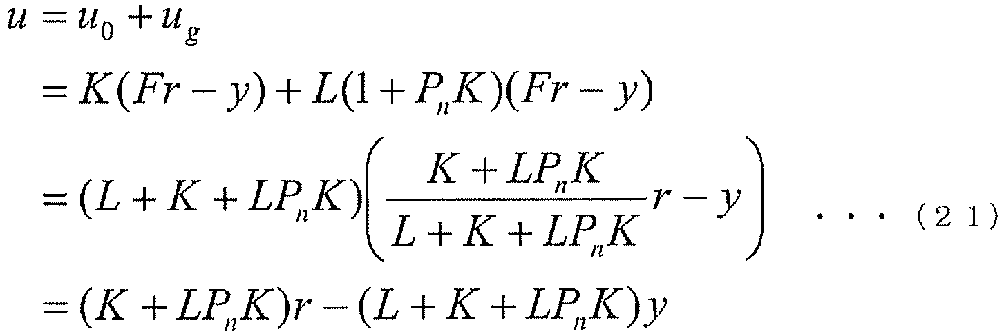
-
Fig. 26 to Fig. 31 show configurations wherein the feedback control systems shown inFig. 2 to Fig. 7 respectively are equivalently converted to a loop type two degrees of freedom control system. InFig. 26 to Fig. 28 , thefeedback controller 101,adders feedback gain 113, and compensatingelements element 129 is added before the input of the manipulated variable y into theadder 102. Also, inFig. 29 to Fig. 31 , the Smith compensator 104 andadder 105 are added to the configurations ofFig. 26 to Fig. 28 respectively, and a first order and time delay transfer function (the compensating element 130) is used in place of the first order transfer function (compensating element 121). - Where, the product of the compensating
element 120 and compensating element 121 (130) inFig. 26 to Fig. 31 is equivalent to the product of the transfer function Pn of thenominal plant 111 and transfer function K of thefeedback controller 101 inFig. 2 to Fig. 7 respectively. Also, a transfer function C of the compensatingelement 129 is described by the following Equation (22) in each case.
[Equation. 22]
feedback gain 113 to be uh, the manipulated variable u in the loop type two degrees of freedom control systems is
[Equation. 23]
- Hereafter, referring to
Fig. 32 to Fig. 34 , a description will be given of an example wherein the control device of this embodiment is applied to a refrigeration cycle system.Fig. 32 shows the configuration of the whole refrigeration cycle system,Fig. 33 shows the configuration of each control device in the refrigeration cycle system, andFig. 34 shows the relationship between manipulated variables (control device outputs) and controlled variables (plant outputs) in the refrigeration cycle system. - The refrigeration cycle system shown in
Fig. 32 is configured to includecontrol devices 11 to 14, arefrigerant pipe 90, acompressor 91, acondenser 92, anexpansion valve 93, anevaporator 94, and sensors S1, S2, S3a, S3b, and S4. Thecompressor 91,condenser 92,expansion valve 93, andevaporator 94 are connected to each other via therefrigerant pipe 90, and a refrigerant circulates inside therefrigerant pipe 90. Also, thecondenser 92 andevaporator 94 include fans F2 and F4 respectively. - A
control device 1m (m = 1, 2, 3, 4) shown inFig. 33 has a configuration the same as that of thecontrol device 1 shown inFig. 1 , a controlled variable ym of the plant 9 and a set point rm are input, and a manipulated variable um of the plant 9 is output. The combinations (pairings) of manipulated variables and controlled variables shown inFig. 34 are an example, and are not limiting. - In the application example of
Fig. 32 , the sensor S1 measures evaporation pressure (low pressure) y1, and thecontrol device 11 outputs the rotation speed u1 of thecompressor 91 as a manipulated variable based on the evaporation pressure y1 as a controlled variable and a set point r1 (not shown). - Also, the sensor S2 measures condensation pressure (high pressure) y2, and the control device 12outputs rotation speed u2 of the fan F2 as a manipulated variable based on the condensation pressure y2 as a controlled variable and a set point r2 (not shown). Also, the sensors S3a and S3b measure inlet temperature Ti and outlet temperature To respectively of the
evaporator 94, and thecontrol device 13 outputs an open degree u3 of theexpansion valve 93 as a manipulated variable based on a degree of overheat y3 (= To - Ti) as a controlled variable and a set point r3 (not shown). Also, the sensor S4 measures a supply temperature y4, and thecontrol device 14 outputs rotation speed u4 of the fan F4 as a manipulated variable based on the supply temperature y4 as a controlled variable and a set point r4 (not shown). - In this way, according to the control device of this embodiment, it is possible to control each controlled variable of the refrigeration cycle system (plant) to the set point. As the instruments configuring the refrigerant cycle are connected to each other via the
refrigerant pipe 90, it may happen that controls by the control devices interfere with each other, and affect other controls as disturbance. Because of this, by the control device of this embodiment being applied to a refrigerant cycle system, it is possible to control the controlled variables to the s while reducing the effect of interference and disturbance. The control device of this embodiment is also applicable to any one instrument of thecompressor 91,condenser 92,expansion valve 93, andevaporator 94 configuring the refrigerant cycle, or to a system wherein these instruments are combined. - As previously described, the design method of the control device of
feedback control system 1 including thefeedback controller 101 anddisturbance feedback 110 is such that, by the transfer function nearest to the characteristics of the plant 9 among the six kinds of transfer function, which are the first order, second order , third order , first order and time delay, second order and time delay, and third order and time delay, being selected as the transfer function Pn of thenominal plant 111, and the transfer function K of thefeedback controller 101 being determined based on the parameters (gain and time constants) of thenominal plant 111, it is possible to easily design a feedback control system control device that, with only the feedback gain L as an tuning parameter and without using state-space representation, balances set point response controlling the controlled variable y to the set point r and disturbance response reducing the effect of the disturbance d. Furthermore, this kind of feedback control system including a disturbance feedback may be equivalently converted to a two degrees of freedom control system. - Also, by the control device 1 (11 to 14) designed in this way being applied to a refrigerant cycle system, it is possible to control the controlled variables to the set points while reducing the effect of interference and disturbance, even when controls by the control devices interfere with each other and affect other controls as disturbance.
- Hereafter, referring to
Fig. 35 to Fig. 37 , a description will be given of a design method of control device in a second embodiment. - In this embodiment, firstly, a feedback control system shown in
Fig. 35 is equivalently converted to a two degrees of freedom PID control system shown inFig. 36 . - A feedback control system control device 3 shown in
Fig. 35 is configured to include, as well as afeedback controller 301 andadder 302, anadder 303 anddisturbance feedback 310 in order to reduce the effect of the disturbance d. Also, thedisturbance feedback 310 is configured to include anominal plant 311, anadder 312, and a feedback gain 313. - A control output (controlled variable y) from the plant 9 and the set point r are input into the
adder 302, and the difference between the set point r and controlled variable y (r - y) is input from theadder 302 into the feedback controller 301 (second feedback controller). Consequently, taking a transfer function of thefeedback controller 301 to be K, the output u0 of thefeedback controller 301 is as in Equation (1) above. - The output u0 of the
feedback controller 301 is inputs into thenominal plant 311 of thedisturbance feedback 310. Consequently, taking a transfer function of thenominal plant 311 to be Pn, the output yn of thenominal plant 311 is as in Equation (2) above. Also, the output yn of thenominal plant 311 and the controlled variable y are input into theadder 312, and the difference e between the output yn of thenominal plant 311 and the controlled variable y (= yn - y) is input from theadder 312 into the feedback gain 313. Consequently, taking the value of the feedback gain 313 to be L (hereafter called the feedback gain L), the disturbance estimation value ud outputs from the feedback gain 313 is as in Equation (3) above. - The output u0 of the
feedback controller 301 and the disturbance estimation value ud are input into theadder 303, and the sum of the output u0 of thefeedback controller 301 and the disturbance estimation value ud is output from theadder 302 as a control input (manipulated variable u) with respect to the plant 9. Consequently, the manipulated variable u is
[Equation. 24]
feedback controller 301 in theadder 303, the disturbance d added to the manipulated variable u in theadder 8 is compensated for. - The reference sign of the disturbance estimation value ud may be changed as appropriate in accordance with the treatment of the disturbance estimation value ud in the
adder 303 or the treatment of the disturbance d in theadder 8. For example, inFig. 35 , when theadder 303 is changed so that the disturbance estimation value ud is subtracted from the output u0 of thefeedback controller 301, the disturbance d can be attenuated by the disturbance estimation value ud being estimated so that the reference sign corresponds with the disturbance d. Also, for example, inFig. 35 , when theadder 8 is changed so that the disturbance d is subtracted from the manipulated variable u, it is sufficient that the disturbance estimation value ud is estimated so that the reference sign corresponds with the disturbance d. - A two degrees of freedom PID control system control device 4 shown in
Fig. 36 is configured to include, as well as afeedback controller 401 andadder 402, afilter 403. The two degrees of freedom PID control system, being such that the set point r is input into the PID control system via thefilter 403, is called a set point filter type (for example, refer to NPL 3). - The set point r is input into the
filter 403, and the output of thefilter 403 and the controlled variable y are input into theadder 402. Also the difference between the output of thefilter 403 and the controlled variable y is input from theadder 402 into the feedback controller 401 (first feedback controller), and the manipulated variable u is output from thefeedback controller 401. Consequently, taking the transfer functions of thefeedback controller 401 and filter 403 to be K' and F respectively, the manipulated variable u is
[Equation. 25]
- In the set point filter type two degrees of freedom PID control system, the transfer function K' of the
feedback controller 401 and the transfer function F of thefilter 403 are expressed as in the following Equation (26) and Equation (27) respectively
[Equation. 26]

[Equation. 27]
- When Equation (2) and Equation (1) are substituted into Equation (3), the following Equation (29) is obtained.
[Equation. 28]
[Equation. 29]
[Equation. 30]
[Equation. 31]

- In this way, a feedback control system including a disturbance feedback can be equivalently converted to a set point filter type two degrees of freedom PID control system, as shown in
Fig. 37 . Further, from Equation (32) and Equation (33), the transfer function K' of thefeedback controller 401 and the transfer function F of thefilter 403 are both determined based on the feedback gain L, transfer function K of thefeedback controller 301, and transfer function Pn of thenominal plant 311. - Next, the transfer function K of the
feedback controller 301 and transfer function Pn of thenominal plant 311 are defined so that the transfer function K' of thefeedback controller 401 and transfer function F of thefilter 403 conform to the forms of Equation (26) and Equation (27) respectively. - In this embodiment, the transfer function Pn of the
nominal plant 311 is defined as a first order transfer function shown in the following Equation (34).
[Equation. 32]
nominal plant 311. Also, using the gain Kpn and time constant Tpn of thenominal plant 311, the transfer function K of thefeedback controller 301 is defined as
[Equation. 35]
- When substituting Equation (34) and Equation (35) into Equation (32), and rearranging in terms of 1/s, the following Equation (36) is obtained.
[Equation. 34]
[Equation. 35]


- Also, when substituting Equation (34) and Equation (35) into Equation (33), and rearranging in terms of s, the following Equation (40) is obtained.
[Equation. 36]
[Equation. 37]


- In this way, from Equation (36) and Equation (40), the transfer function K' of the
feedback controller 401 and transfer function F of thefilter 403 in the set point filter type two degrees of freedom PID control system after equivalent conversion are determined based on the gain Kpn and time constant Tpn of thenominal plant 311 and on the feedback gain L. Also, because of this, the proportional gain Kp is given by Equation (37), the integral time TI is given by Equation (38) and Equation (41), and the two degrees of freedom parameter α is given by Equation (42).
Furthermore, from Equation (39) and Equation (43), the derivative time TD is 0, and setting of the two degrees of freedom parameter β is unnecessary. - As heretofore described, of this embodiment is such that the engineer, firstly, carries out equivalent conversion of the feedback control system including a disturbance feedback of
Fig. 35 to the set point filter type two degrees of freedom PID control system ofFig. 36 . Next, in the set point filter type two degrees of freedom PID control system after equivalent conversion, the derivative time TD of the transfer function K' of thefeedback controller 401 and transfer function F of thefilter 403 is set to 0. Also, in the feedback control system before equivalent conversion, a first order transfer function applied to the transfer function Pn of thenominal plant 311, and furthermore, the transfer function K of thefeedback controller 301 is determined based on the gain Kpn and time constant Tpn of thenominal plant 311. - Because of this, the transfer function K' of the
feedback controller 401 and transfer function F of thefilter 403 are determined based on the gain Kpn and time constant Tpn of thenominal plant 311, and on the feedback gain L. Therefore, the engineer, by identifying the first order transfer function of thenominal plant 311 from experiment or simulation data in accordance with a least squares method, a prediction error method, or the like, thus obtaining the gain Kpn and time constant Tpn, can determine the transfer function K' of thefeedback controller 401 and transfer function F of thefilter 403, with only the feedback gain L as an tuning parameter. Further, as the control device 4 designed in this way outputs the same manipulated variable u as the control device 3 including disturbance feedback, it is possible to balance set point response controlling the controlled variable y to the set point r and disturbance response reducing the effect of the disturbance d. - Also, the control device 4 of this embodiment is applicable to the kind of refrigerant cycle system shown in
Fig. 32 , in the same way as thecontrol device 1 of the first embodiment. Thecontrol device 1m (m = 1, 2, 3, 4) shown inFig. 38 being of a configuration the same as that of the control device 4 shown inFig. 36 , the controlled variable ym of the plant 9 and the set point rm thereof are input, and the manipulated variable um of the plant 9 is output. - As previously described, the design method of control device whereby the controlled variable y of the plant 9 is controlled to the set point r is such that, by the transfer function K' of the feedback controller 401 (first feedback controller) and the transfer function F of the
filter 403 in the set point filter type two degrees of freedom PID control system ofFig. 36 both being determined based on the feedback gain L, transfer function K of the feedback controller 301 (second feedback controller), and transfer function Pn of thenominal plant 311 in the feedback control system including disturbance feedback ofFig. 35 , it is possible to easily design a control device such that a feedback control system including a disturbance feedback is equivalently converted to a set point filter type two degrees of freedom PID control system, without using an state-space representation. Further, as the control device 4 designed in this way outputs the same manipulated variable u as the control device 3 including disturbance feedback, it is possible to balance set point response controlling the controlled variable y to the set point r and disturbance response reducing the effect of the disturbance d. - Also, by the derivative time TD of the transfer function K' of the
feedback controller 401 and transfer function F of thefilter 403 being set to 0 in the set point filter type two degrees of freedom PID control system after equivalent conversion, a first order transfer function being adopted as the transfer function Pn of thenominal plant 311 in the feedback control system before equivalent conversion, and furthermore, the transfer function K of thefeedback controller 301 being determined based on the gain Kpn and time constant Tpn of thenominal plant 311, the transfer function K' of thefeedback controller 401 and transfer function F of thefilter 403 can be determined based on the gain Kpn and time constant Tpn of thenominal plant 311, and on the feedback gain L. - Also, by identifying the first order transfer function of the
nominal plant 311, thus obtaining the gain Kpn and time constant Tpn, it is possible to determine the transfer function K' of thefeedback controller 401 and transfer function F of thefilter 403, with only the feedback gain L as a tuning parameter. That is, as opposed to normally needing to tune five parameters (the proportional gain KP, integral time TI, derivative time TD, and two degrees of freedom parameters α and P) when designing a two degrees of freedom PID control system, as shown in Equation (26) and Equation (27), the design method of control device of the heretofore described embodiment is such that it is possible to design with only the one tuning parameter (L). - Also, by the control device 4 (11 to 14) designed in this way being applied to a refrigerant cycle system, it is possible to control the controlled variables to the set points while reducing the effect of interference and disturbance, even when controls by the control devices interfere with each other and affect other controls as disturbance.
- The heretofore described embodiments are for facilitating understanding of the invention, not for limiting interpretation of the invention. The invention may be changed or improved without departing from the scope thereof, and equivalents thereof are also included in the invention.
-
- 1 to 4
- Control device
- 8
- Adder
- 9
- Plant
- 1m (11 to 14)
- Control device
- 90
- Refrigerant pipe
- 91
- Compressor
- 92
- Condenser
- 93
- Expansion valve
- 94
- Evaporator
- 101, 201
- Feedback controller
- 102, 103, 105, 112, 123, 125, 127, 202
- Adder
- 104
- Smith compensator
- 110
- Disturbance feedback
- 111
- Nominal plant
- 113
- Feedback gain
- 120 to 122, 124, 126, 128 to 130
- Compensating element
- 301, 401
- Feedback controller
- 302, 303, 312, 402
- Adder
- 310
- Disturbance feedback
- 311
- Nominal plant
- 313
- Feedback gain
- 403
- Filter
- F2, F4
- Fan
- S1, S2, S3a, S3b, S4
- Sensor
Claims (11)
- A method of designing a control device that controls a controlled variable of a plant to a set point, the design method of control device being characterized in that
the control device is configured as a feedback control system, which includes a feedback controller into which is input the difference between the set point and controlled variable and
a disturbance feedback that outputs a disturbance estimation value that is the difference between the output of a nominal plant into which is input the output of the feedback controller and the controlled variable multiplied by a feedback gain,
and which outputs a manipulated variable of the plant based on the output of the feedback controller and the disturbance estimation value, wherein
one of a first order transfer function, second order transfer function, third order transfer function, first order and time delay transfer function, second order and time delay transfer function, and third order and time delay transfer function is selected as a transfer function of the nominal plant in accordance with the characteristics of the plant, and
a transfer function of the feedback controller is determined based on a gain and time constant of the nominal plant. - A method of designing the control device according to claim 1, characterized in that
when the first order transfer function shown in the following Equation (1) is selected as a transfer function Pn of the nominal plant, a transfer function K of the feedback controller is determined as in the following Equation (2) based on a gain Kn and time constant Tn of the nominal plant,
when the second order transfer function shown in the following Equation (3) is selected as the transfer function Pn of the nominal plant, the transfer function K of the feedback controller is determined as in the following Equation (4) based on the gain Kn and time constants T1n and σn of the nominal plant, and when the third order transfer function shown in the following Equation (5) is selected as the transfer function Pn of the nominal plant, the transfer function K of the feedback controller is determined as in the following Equation (6) based on the gain Kn and time constants T1n, T2n, and σn of the nominal plant.
[Equation. 1]


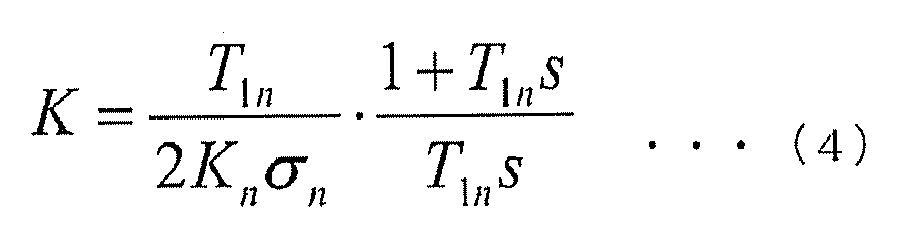


- A method of designing the control device according to claim 1, characterized in that when the first order and time delay transfer function, second order and time delay transfer function, or third order and time delay transfer function is selected as the transfer function of the nominal plant, a Smith compensator is appended to the transfer function of the feedback controller.
- A method of designing the control device according to any of claim 1 to claim 3,
characterized in that
the feedback control system wherein the transfer function of the nominal plant has been selected and the transfer function of the feedback controller has been determined is further equivalently converted to a two degrees of freedom control system. - A method of designing a control device configured as a set point filter type two degrees of freedom PID control system, which includes
a filter into which is input a set point of a controlled variable of a plant and
a first feedback controller into which is input the difference between the output of the filter and the controlled variable and that outputs a manipulated variable of the plant,
and which controls the controlled variable to the set point,
the design method of control device being characterized in that a feedback control system including a second feedback controller into which is input the difference between the set point and controlled variable and a disturbance feedback that outputs the difference between the output of a nominal plant into which is input the output of the second feedback controller and the controlled variable multiplied by a feedback gain is equivalently converted to the set point filter type two degree of freedom PID control system, wherein
the equivalent conversion is such that a transfer function of the filter and a transfer function of the first feedback controller are both determined based on the feedback gain, a transfer function of the second feedback controller, and a transfer function of the nominal plant. - A method of designing the control device according to claim 5, characterized in that
derivative time of the transfer function of the filter and the transfer function of the first feedback controller is 0,
the transfer function of the nominal plant is a first order transfer function, and the transfer function of the second feedback controller is determined based on a gain and time constant of the nominal plant. - A method of designing the control device according to claim 6, characterized in that the first order transfer function is identified, obtaining the gain and time constant of the nominal plant, and
the transfer function of the filter and transfer function of the first feedback controller are determined based on the obtained gain and time constant of the nominal plant, with only the feedback gain as a tuning parameter. - A control device, characterized by being designed depending on the method of designing the control device according to any of claim 1 to claim 7.
- A control device that controls a controlled variable of a plant to a set point,
the control device being configured as a set point filter type two degrees of freedom PID control system including
a filter into which is input the set point and
a first feedback controller into which is input the difference between the output of the filter and the controlled variable and that outputs a manipulated variable of the plant, wherein
a feedback control system including a second feedback controller into which is input the difference between the set point and controlled variable and a disturbance feedback that outputs the difference between the output of a nominal plant into which is input the output of the second feedback controller and the controlled variable multiplied by a feedback gain is equivalently converted, wherein
a transfer function of the filter and a transfer function of the first feedback controller are both determined based on the feedback gain, a transfer function of the second feedback controller, and a transfer function of the nominal plant. - The control device according to claim 9, characterized in that
derivative time of the transfer function of the filter and the transfer function of the first feedback controller is 0,
the transfer function of the nominal plant is a first order transfer function, and the transfer function of the second feedback controller is determined based on a gain and time constant of the nominal plant. - The control device according to any of claim 8 to claim 10, characterized in that
the plant is any one instrument of a compressor, condenser, expansion valve, and evaporator configuring a refrigerant cycle, or to a system wherein these instruments are combined.
Applications Claiming Priority (3)
| Application Number | Priority Date | Filing Date | Title |
|---|---|---|---|
| JP2012263080 | 2012-11-30 | ||
| JP2013121732 | 2013-06-10 | ||
| PCT/JP2013/081278 WO2014084098A1 (en) | 2012-11-30 | 2013-11-20 | Control device design method and control device |
Publications (3)
| Publication Number | Publication Date |
|---|---|
| EP2927757A1 true EP2927757A1 (en) | 2015-10-07 |
| EP2927757A4 EP2927757A4 (en) | 2016-08-31 |
| EP2927757B1 EP2927757B1 (en) | 2018-09-05 |
Family
ID=50827740
Family Applications (1)
| Application Number | Title | Priority Date | Filing Date |
|---|---|---|---|
| EP13859458.5A Active EP2927757B1 (en) | 2012-11-30 | 2013-11-20 | Control device design method and control device |
Country Status (4)
| Country | Link |
|---|---|
| US (1) | US10409229B2 (en) |
| EP (1) | EP2927757B1 (en) |
| JP (1) | JP5817940B2 (en) |
| WO (1) | WO2014084098A1 (en) |
Families Citing this family (15)
| Publication number | Priority date | Publication date | Assignee | Title |
|---|---|---|---|---|
| US10324424B2 (en) | 2013-03-11 | 2019-06-18 | Johnson Controls Technology Company | Control system with response time estimation and automatic operating parameter adjustment |
| US9395708B2 (en) | 2013-03-11 | 2016-07-19 | Johnson Controls Technology Company | Systems and methods for adaptive sampling rate adjustment |
| EP3252548B1 (en) * | 2016-06-03 | 2021-11-17 | Johnson Controls Technology Company | Control system with response time estimation and automatic operating parameter adjustment |
| JP6769219B2 (en) * | 2016-09-30 | 2020-10-14 | ブラザー工業株式会社 | Numerical control device |
| WO2018095530A1 (en) * | 2016-11-24 | 2018-05-31 | Renesas Electronics Europe Gmbh | Adaptive control system |
| US10509629B2 (en) * | 2017-03-22 | 2019-12-17 | Kabushiki Kaisha Toshiba | Control device |
| CN108733910B (en) * | 2018-05-16 | 2022-04-29 | 广西电网有限责任公司电力科学研究院 | A method for realizing automatic derivation of state equation of power system |
| JP7219115B2 (en) * | 2018-08-13 | 2023-02-07 | Thk株式会社 | Disturbance suppression control device |
| JP7314710B2 (en) * | 2019-08-14 | 2023-07-26 | 富士電機株式会社 | CONTROLLER, DESIGN METHOD OF CONTROLLER |
| CN110837254B (en) * | 2019-11-04 | 2022-10-28 | 哈尔滨工程大学 | Longitudinal motion control method for hydrofoil craft |
| CN113110252B (en) * | 2021-05-19 | 2022-03-18 | 广东电网有限责任公司 | Control method of double-parameter novel basic controller |
| CN113589681A (en) * | 2021-08-02 | 2021-11-02 | 广东工业大学 | Anti-interference controller easy to set and setting method thereof |
| CN116736753A (en) * | 2022-03-08 | 2023-09-12 | 知微电子有限公司 | Feedback control systems and related methods |
| CN114755914B (en) * | 2022-04-11 | 2024-06-25 | 中国航发控制系统研究所 | IMC-PID-based aeroengine servo controller design method |
| CN115509121B (en) * | 2022-10-27 | 2024-08-30 | 中国科学院光电技术研究所 | Method for setting parameters of PI-Smith controller in pure time-lag system |
Family Cites Families (8)
| Publication number | Priority date | Publication date | Assignee | Title |
|---|---|---|---|---|
| JPH08273827A (en) | 1995-03-30 | 1996-10-18 | Fuji Electric Co Ltd | Electric current control device for arc furnace |
| JP2001265408A (en) * | 2000-03-22 | 2001-09-28 | Shuichi Yokoyama | Device and method for controlling temperature of heat system plant |
| JP2002287804A (en) | 2001-03-28 | 2002-10-04 | Seiko Instruments Inc | Reference model adaptive control system and reference model adaptive control method |
| ITTO20030792A1 (en) * | 2002-10-08 | 2004-04-09 | Danfoss As | VALVE CONTROL DEVICE AND PROCEDURE |
| JP4177235B2 (en) * | 2003-11-11 | 2008-11-05 | 三菱化学株式会社 | Plant control method and apparatus |
| JP2005267296A (en) * | 2004-03-19 | 2005-09-29 | Yaskawa Electric Corp | Servo control device |
| JP2008097390A (en) * | 2006-10-13 | 2008-04-24 | Fuji Electric Systems Co Ltd | Model following control device applied to controlled objects including dead time |
| JP2009116515A (en) * | 2007-11-05 | 2009-05-28 | Fuji Electric Systems Co Ltd | PID parameter adjustment support device |
-
2013
- 2013-11-20 JP JP2014550143A patent/JP5817940B2/en active Active
- 2013-11-20 WO PCT/JP2013/081278 patent/WO2014084098A1/en not_active Ceased
- 2013-11-20 EP EP13859458.5A patent/EP2927757B1/en active Active
-
2015
- 2015-04-06 US US14/679,588 patent/US10409229B2/en active Active
Also Published As
| Publication number | Publication date |
|---|---|
| JPWO2014084098A1 (en) | 2017-01-05 |
| EP2927757A4 (en) | 2016-08-31 |
| US20150212498A1 (en) | 2015-07-30 |
| US10409229B2 (en) | 2019-09-10 |
| WO2014084098A1 (en) | 2014-06-05 |
| JP5817940B2 (en) | 2015-11-18 |
| EP2927757B1 (en) | 2018-09-05 |
Similar Documents
| Publication | Publication Date | Title |
|---|---|---|
| EP2927757B1 (en) | Control device design method and control device | |
| US7331191B2 (en) | Heating, ventilation and air conditioning (HVAC) system and method using feedback linearization | |
| Azam et al. | A dual Kalman filter approach for state estimation via output-only acceleration measurements | |
| Dougherty et al. | A practical multiple model adaptive strategy for single-loop MPC | |
| EP2492762B1 (en) | Method and system for controlling a multivariable system with limits | |
| US10409232B2 (en) | Engineering tool and method for parameterizing a model-based predictive controller | |
| US20160132027A1 (en) | Dither switching extremum seeking control | |
| JP2009537880A (en) | Axis position control method based on Generalized Predictive Control (GPC) | |
| CN113433819B (en) | A system identification method and computer equipment | |
| US9523365B2 (en) | Decoupling of controlled variables in a fluid conveying system with dead time | |
| EP2884354A1 (en) | Model-based predictive controller with steady-state model adaptation | |
| Höckerdal et al. | EKF-based adaptation of look-up tables with an air mass-flow sensor application | |
| Andrieu et al. | Continuous discrete observer with updated sampling period | |
| US20100004895A1 (en) | Adaptive resolver compensation controller | |
| Salsbury et al. | An extremum-seeking control method driven by input–output correlation | |
| EP1406136B1 (en) | Estimation of process variables | |
| Cortes-Romero et al. | Discrete FIR filter-based Control | |
| Zhang et al. | Modeling and output feedback control of automotive air conditioning system | |
| CN118915698B (en) | Test system, method, device, equipment and storage medium | |
| Natori et al. | Analysis and design of time delayed control systems with communication disturbance observer | |
| EP4296586A1 (en) | System and method for estimating electrical power consumption of an air-conditioning system | |
| Rodríguez et al. | Robust and decoupling approach to PID control of vapour-compression refrigeration systems | |
| Yang et al. | Practical non-linear model predictive control pnmpc: Algorithm implementations | |
| Sørensen | Model based control of reefer container systems | |
| JP7089335B2 (en) | Control device |
Legal Events
| Date | Code | Title | Description |
|---|---|---|---|
| PUAI | Public reference made under article 153(3) epc to a published international application that has entered the european phase |
Free format text: ORIGINAL CODE: 0009012 |
|
| 17P | Request for examination filed |
Effective date: 20150401 |
|
| AK | Designated contracting states |
Kind code of ref document: A1 Designated state(s): AL AT BE BG CH CY CZ DE DK EE ES FI FR GB GR HR HU IE IS IT LI LT LU LV MC MK MT NL NO PL PT RO RS SE SI SK SM TR |
|
| AX | Request for extension of the european patent |
Extension state: BA ME |
|
| DAX | Request for extension of the european patent (deleted) | ||
| REG | Reference to a national code |
Ref country code: DE Ref legal event code: R079 Ref document number: 602013043340 Country of ref document: DE Free format text: PREVIOUS MAIN CLASS: G05B0011360000 Ipc: G05B0011420000 |
|
| RIC1 | Information provided on ipc code assigned before grant |
Ipc: G05B 11/42 20060101AFI20160721BHEP Ipc: G05B 19/19 20060101ALI20160721BHEP |
|
| RA4 | Supplementary search report drawn up and despatched (corrected) |
Effective date: 20160728 |
|
| 17Q | First examination report despatched |
Effective date: 20170523 |
|
| GRAP | Despatch of communication of intention to grant a patent |
Free format text: ORIGINAL CODE: EPIDOSNIGR1 |
|
| INTG | Intention to grant announced |
Effective date: 20180426 |
|
| GRAS | Grant fee paid |
Free format text: ORIGINAL CODE: EPIDOSNIGR3 |
|
| GRAA | (expected) grant |
Free format text: ORIGINAL CODE: 0009210 |
|
| AK | Designated contracting states |
Kind code of ref document: B1 Designated state(s): AL AT BE BG CH CY CZ DE DK EE ES FI FR GB GR HR HU IE IS IT LI LT LU LV MC MK MT NL NO PL PT RO RS SE SI SK SM TR |
|
| REG | Reference to a national code |
Ref country code: GB Ref legal event code: FG4D |
|
| REG | Reference to a national code |
Ref country code: CH Ref legal event code: EP |
|
| REG | Reference to a national code |
Ref country code: AT Ref legal event code: REF Ref document number: 1038545 Country of ref document: AT Kind code of ref document: T Effective date: 20180915 |
|
| REG | Reference to a national code |
Ref country code: IE Ref legal event code: FG4D |
|
| REG | Reference to a national code |
Ref country code: DE Ref legal event code: R096 Ref document number: 602013043340 Country of ref document: DE |
|
| REG | Reference to a national code |
Ref country code: FR Ref legal event code: PLFP Year of fee payment: 6 |
|
| REG | Reference to a national code |
Ref country code: NL Ref legal event code: MP Effective date: 20180905 |
|
| REG | Reference to a national code |
Ref country code: LT Ref legal event code: MG4D |
|
| PG25 | Lapsed in a contracting state [announced via postgrant information from national office to epo] |
Ref country code: LT Free format text: LAPSE BECAUSE OF FAILURE TO SUBMIT A TRANSLATION OF THE DESCRIPTION OR TO PAY THE FEE WITHIN THE PRESCRIBED TIME-LIMIT Effective date: 20180905 Ref country code: BG Free format text: LAPSE BECAUSE OF FAILURE TO SUBMIT A TRANSLATION OF THE DESCRIPTION OR TO PAY THE FEE WITHIN THE PRESCRIBED TIME-LIMIT Effective date: 20181205 Ref country code: SE Free format text: LAPSE BECAUSE OF FAILURE TO SUBMIT A TRANSLATION OF THE DESCRIPTION OR TO PAY THE FEE WITHIN THE PRESCRIBED TIME-LIMIT Effective date: 20180905 Ref country code: RS Free format text: LAPSE BECAUSE OF FAILURE TO SUBMIT A TRANSLATION OF THE DESCRIPTION OR TO PAY THE FEE WITHIN THE PRESCRIBED TIME-LIMIT Effective date: 20180905 Ref country code: GR Free format text: LAPSE BECAUSE OF FAILURE TO SUBMIT A TRANSLATION OF THE DESCRIPTION OR TO PAY THE FEE WITHIN THE PRESCRIBED TIME-LIMIT Effective date: 20181206 Ref country code: NO Free format text: LAPSE BECAUSE OF FAILURE TO SUBMIT A TRANSLATION OF THE DESCRIPTION OR TO PAY THE FEE WITHIN THE PRESCRIBED TIME-LIMIT Effective date: 20181205 Ref country code: FI Free format text: LAPSE BECAUSE OF FAILURE TO SUBMIT A TRANSLATION OF THE DESCRIPTION OR TO PAY THE FEE WITHIN THE PRESCRIBED TIME-LIMIT Effective date: 20180905 |
|
| REG | Reference to a national code |
Ref country code: AT Ref legal event code: MK05 Ref document number: 1038545 Country of ref document: AT Kind code of ref document: T Effective date: 20180905 |
|
| PG25 | Lapsed in a contracting state [announced via postgrant information from national office to epo] |
Ref country code: LV Free format text: LAPSE BECAUSE OF FAILURE TO SUBMIT A TRANSLATION OF THE DESCRIPTION OR TO PAY THE FEE WITHIN THE PRESCRIBED TIME-LIMIT Effective date: 20180905 Ref country code: AL Free format text: LAPSE BECAUSE OF FAILURE TO SUBMIT A TRANSLATION OF THE DESCRIPTION OR TO PAY THE FEE WITHIN THE PRESCRIBED TIME-LIMIT Effective date: 20180905 Ref country code: HR Free format text: LAPSE BECAUSE OF FAILURE TO SUBMIT A TRANSLATION OF THE DESCRIPTION OR TO PAY THE FEE WITHIN THE PRESCRIBED TIME-LIMIT Effective date: 20180905 |
|
| PG25 | Lapsed in a contracting state [announced via postgrant information from national office to epo] |
Ref country code: ES Free format text: LAPSE BECAUSE OF FAILURE TO SUBMIT A TRANSLATION OF THE DESCRIPTION OR TO PAY THE FEE WITHIN THE PRESCRIBED TIME-LIMIT Effective date: 20180905 Ref country code: IS Free format text: LAPSE BECAUSE OF FAILURE TO SUBMIT A TRANSLATION OF THE DESCRIPTION OR TO PAY THE FEE WITHIN THE PRESCRIBED TIME-LIMIT Effective date: 20190105 Ref country code: AT Free format text: LAPSE BECAUSE OF FAILURE TO SUBMIT A TRANSLATION OF THE DESCRIPTION OR TO PAY THE FEE WITHIN THE PRESCRIBED TIME-LIMIT Effective date: 20180905 Ref country code: IT Free format text: LAPSE BECAUSE OF FAILURE TO SUBMIT A TRANSLATION OF THE DESCRIPTION OR TO PAY THE FEE WITHIN THE PRESCRIBED TIME-LIMIT Effective date: 20180905 Ref country code: EE Free format text: LAPSE BECAUSE OF FAILURE TO SUBMIT A TRANSLATION OF THE DESCRIPTION OR TO PAY THE FEE WITHIN THE PRESCRIBED TIME-LIMIT Effective date: 20180905 Ref country code: PL Free format text: LAPSE BECAUSE OF FAILURE TO SUBMIT A TRANSLATION OF THE DESCRIPTION OR TO PAY THE FEE WITHIN THE PRESCRIBED TIME-LIMIT Effective date: 20180905 Ref country code: NL Free format text: LAPSE BECAUSE OF FAILURE TO SUBMIT A TRANSLATION OF THE DESCRIPTION OR TO PAY THE FEE WITHIN THE PRESCRIBED TIME-LIMIT Effective date: 20180905 Ref country code: RO Free format text: LAPSE BECAUSE OF FAILURE TO SUBMIT A TRANSLATION OF THE DESCRIPTION OR TO PAY THE FEE WITHIN THE PRESCRIBED TIME-LIMIT Effective date: 20180905 Ref country code: CZ Free format text: LAPSE BECAUSE OF FAILURE TO SUBMIT A TRANSLATION OF THE DESCRIPTION OR TO PAY THE FEE WITHIN THE PRESCRIBED TIME-LIMIT Effective date: 20180905 |
|
| PG25 | Lapsed in a contracting state [announced via postgrant information from national office to epo] |
Ref country code: PT Free format text: LAPSE BECAUSE OF FAILURE TO SUBMIT A TRANSLATION OF THE DESCRIPTION OR TO PAY THE FEE WITHIN THE PRESCRIBED TIME-LIMIT Effective date: 20190105 Ref country code: SM Free format text: LAPSE BECAUSE OF FAILURE TO SUBMIT A TRANSLATION OF THE DESCRIPTION OR TO PAY THE FEE WITHIN THE PRESCRIBED TIME-LIMIT Effective date: 20180905 Ref country code: SK Free format text: LAPSE BECAUSE OF FAILURE TO SUBMIT A TRANSLATION OF THE DESCRIPTION OR TO PAY THE FEE WITHIN THE PRESCRIBED TIME-LIMIT Effective date: 20180905 |
|
| REG | Reference to a national code |
Ref country code: DE Ref legal event code: R097 Ref document number: 602013043340 Country of ref document: DE |
|
| REG | Reference to a national code |
Ref country code: CH Ref legal event code: PL |
|
| PLBE | No opposition filed within time limit |
Free format text: ORIGINAL CODE: 0009261 |
|
| STAA | Information on the status of an ep patent application or granted ep patent |
Free format text: STATUS: NO OPPOSITION FILED WITHIN TIME LIMIT |
|
| PG25 | Lapsed in a contracting state [announced via postgrant information from national office to epo] |
Ref country code: LU Free format text: LAPSE BECAUSE OF NON-PAYMENT OF DUE FEES Effective date: 20181120 Ref country code: MC Free format text: LAPSE BECAUSE OF FAILURE TO SUBMIT A TRANSLATION OF THE DESCRIPTION OR TO PAY THE FEE WITHIN THE PRESCRIBED TIME-LIMIT Effective date: 20180905 Ref country code: DK Free format text: LAPSE BECAUSE OF FAILURE TO SUBMIT A TRANSLATION OF THE DESCRIPTION OR TO PAY THE FEE WITHIN THE PRESCRIBED TIME-LIMIT Effective date: 20180905 |
|
| 26N | No opposition filed |
Effective date: 20190606 |
|
| REG | Reference to a national code |
Ref country code: BE Ref legal event code: MM Effective date: 20181130 |
|
| REG | Reference to a national code |
Ref country code: IE Ref legal event code: MM4A |
|
| GBPC | Gb: european patent ceased through non-payment of renewal fee |
Effective date: 20181205 |
|
| PG25 | Lapsed in a contracting state [announced via postgrant information from national office to epo] |
Ref country code: LI Free format text: LAPSE BECAUSE OF NON-PAYMENT OF DUE FEES Effective date: 20181130 Ref country code: CH Free format text: LAPSE BECAUSE OF NON-PAYMENT OF DUE FEES Effective date: 20181130 Ref country code: SI Free format text: LAPSE BECAUSE OF FAILURE TO SUBMIT A TRANSLATION OF THE DESCRIPTION OR TO PAY THE FEE WITHIN THE PRESCRIBED TIME-LIMIT Effective date: 20180905 |
|
| PG25 | Lapsed in a contracting state [announced via postgrant information from national office to epo] |
Ref country code: IE Free format text: LAPSE BECAUSE OF NON-PAYMENT OF DUE FEES Effective date: 20181120 |
|
| PG25 | Lapsed in a contracting state [announced via postgrant information from national office to epo] |
Ref country code: BE Free format text: LAPSE BECAUSE OF NON-PAYMENT OF DUE FEES Effective date: 20181130 |
|
| PG25 | Lapsed in a contracting state [announced via postgrant information from national office to epo] |
Ref country code: GB Free format text: LAPSE BECAUSE OF NON-PAYMENT OF DUE FEES Effective date: 20181205 |
|
| PG25 | Lapsed in a contracting state [announced via postgrant information from national office to epo] |
Ref country code: MT Free format text: LAPSE BECAUSE OF NON-PAYMENT OF DUE FEES Effective date: 20181120 |
|
| PG25 | Lapsed in a contracting state [announced via postgrant information from national office to epo] |
Ref country code: TR Free format text: LAPSE BECAUSE OF FAILURE TO SUBMIT A TRANSLATION OF THE DESCRIPTION OR TO PAY THE FEE WITHIN THE PRESCRIBED TIME-LIMIT Effective date: 20180905 |
|
| PG25 | Lapsed in a contracting state [announced via postgrant information from national office to epo] |
Ref country code: MK Free format text: LAPSE BECAUSE OF NON-PAYMENT OF DUE FEES Effective date: 20180905 Ref country code: HU Free format text: LAPSE BECAUSE OF FAILURE TO SUBMIT A TRANSLATION OF THE DESCRIPTION OR TO PAY THE FEE WITHIN THE PRESCRIBED TIME-LIMIT; INVALID AB INITIO Effective date: 20131120 Ref country code: CY Free format text: LAPSE BECAUSE OF FAILURE TO SUBMIT A TRANSLATION OF THE DESCRIPTION OR TO PAY THE FEE WITHIN THE PRESCRIBED TIME-LIMIT Effective date: 20180905 |
|
| PGFP | Annual fee paid to national office [announced via postgrant information from national office to epo] |
Ref country code: FR Payment date: 20250930 Year of fee payment: 13 |
|
| PGFP | Annual fee paid to national office [announced via postgrant information from national office to epo] |
Ref country code: DE Payment date: 20250930 Year of fee payment: 13 |