EP2927724A1 - Fiber optic distribution device - Google Patents
Fiber optic distribution device Download PDFInfo
- Publication number
- EP2927724A1 EP2927724A1 EP14163374.3A EP14163374A EP2927724A1 EP 2927724 A1 EP2927724 A1 EP 2927724A1 EP 14163374 A EP14163374 A EP 14163374A EP 2927724 A1 EP2927724 A1 EP 2927724A1
- Authority
- EP
- European Patent Office
- Prior art keywords
- fiber optic
- management unit
- housing
- distribution device
- interior space
- Prior art date
- Legal status (The legal status is an assumption and is not a legal conclusion. Google has not performed a legal analysis and makes no representation as to the accuracy of the status listed.)
- Granted
Links
- 239000000835 fiber Substances 0.000 title claims abstract description 290
- 238000009423 ventilation Methods 0.000 claims description 3
- 239000013307 optical fiber Substances 0.000 description 17
- 238000009434 installation Methods 0.000 description 2
- 239000007858 starting material Substances 0.000 description 2
- 230000005540 biological transmission Effects 0.000 description 1
- 230000001419 dependent effect Effects 0.000 description 1
- 230000001681 protective effect Effects 0.000 description 1
Images



Classifications
-
- G—PHYSICS
- G02—OPTICS
- G02B—OPTICAL ELEMENTS, SYSTEMS OR APPARATUS
- G02B6/00—Light guides; Structural details of arrangements comprising light guides and other optical elements, e.g. couplings
- G02B6/44—Mechanical structures for providing tensile strength and external protection for fibres, e.g. optical transmission cables
- G02B6/4439—Auxiliary devices
- G02B6/444—Systems or boxes with surplus lengths
- G02B6/4452—Distribution frames
- G02B6/44524—Distribution frames with frame parts or auxiliary devices mounted on the frame and collectively not covering a whole width of the frame or rack
-
- G—PHYSICS
- G02—OPTICS
- G02B—OPTICAL ELEMENTS, SYSTEMS OR APPARATUS
- G02B6/00—Light guides; Structural details of arrangements comprising light guides and other optical elements, e.g. couplings
- G02B6/44—Mechanical structures for providing tensile strength and external protection for fibres, e.g. optical transmission cables
- G02B6/4439—Auxiliary devices
- G02B6/444—Systems or boxes with surplus lengths
- G02B6/44528—Patch-cords; Connector arrangements in the system or in the box
Definitions
- DE 20 2005 019 319 U1 discloses a fiber optic distribution device designed as a street cabinet.
- the street cabinet according to DE 20 2005 019 319 U1 comprises a housing defining an interior space of the street cabinet, wherein at least one fiber optic cable can be inserted from an exterior into the interior space of the housing and passed out from the interior space of the housing in the exterior.
- a fiber optic management unit is mounted in the housing, wherein the fiber optic management unit comprises a back wall carrying over-length handling elements and a front wall hinged to the back wall carrying splice trays and strain relief elements.
- the or each fiber optic management unit is mounted on mounting rails in such a way that the respective fiber optic management unit having a first orientation in an upright position of the same can be horizontally pulled out from the interior space of the housing and horizontally pushed into the interior space of the housing in said first orientation; and that the respective fiber optic management unit being pulled out from the interior space of the housing can be pivoted around a vertical rotation axis from said first orientation into a second orientation and vice versa from said second orientation into the first orientation while maintaining the upright position of the respective fiber optic management unit.
- the fiber optic distribution device of the present application is at the same time modular, scalable on demand and provides good access to the optical fibers and fiber connections handled in the fiber optic distribution device.
- the fiber optic distribution device gives the flexibility to upgrade existing networks for new applications, like vectoring. It consists of modular fiber optic management units which can be configured individually according to the relevant needs or according to the available size of the interior space of the housing of the fiber optic distribution device.
- the mounting rails provide a slide-in/slide-out mechanism providing excellent access to the optical fibers for the field installation.
- the cable entry module provides a top module of the respective fiber optic management unit, the or each splice module is positioned below the cable entry module, and the or each patch module is positioned below the or each splice module.
- the fiber optic management unit 30 comprises two splice modules 39 each having several splice trays 52, wherein the number of several splice trays 52 of these splice module 39 can be identical or different.
- the fiber optic management unit 30 comprises further a WDM module 41 positioned below the or each splice module and the or each patch module 40.
- the WDM module 41 comprises a wave division multiplexing filter 63.
- the WDM module 41 comprises a back wall 65 carrying the wave division multiplexing filter 63 and fiber guide elements 71.
- the guide elements 71 can be used over over-length storage.
- the WDM module 41 further comprises at least one side wall 64.
Landscapes
- Physics & Mathematics (AREA)
- General Physics & Mathematics (AREA)
- Optics & Photonics (AREA)
- Light Guides In General And Applications Therefor (AREA)
- Mechanical Coupling Of Light Guides (AREA)
Abstract
Description
- The present patent application relates to a fiber optic distribution device comprising at least one fiber optic management unit.
- When designing data transmission networks comprising optical fibers, it is necessary to handle optical fibers, especially to connect optical fibers to one another. Junctions between optical fibers can be provided by patch connections and splice connections. Such junctions need to be handled both outside buildings and inside buildings. Outside buildings, junctions between optical fibers are accommodated in so called cable sleeves or street cabinets. Inside buildings, junctions between optical fiber are handled in so called distribution cabinets or distribution frames. So called wall boxes are used for the handling of junctions between optical fibers both outside buildings and inside buildings.
-
DE 20 2005 019 319 U1 discloses a fiber optic distribution device designed as a street cabinet. The street cabinet according toDE 20 2005 019 319 U1 comprises a housing defining an interior space of the street cabinet, wherein at least one fiber optic cable can be inserted from an exterior into the interior space of the housing and passed out from the interior space of the housing in the exterior. A fiber optic management unit is mounted in the housing, wherein the fiber optic management unit comprises a back wall carrying over-length handling elements and a front wall hinged to the back wall carrying splice trays and strain relief elements. - The present application is based on the object to provide a novel fiber optic distribution device suitable for handling optical fibers both outside buildings and inside buildings, the fiber optic distribution device being modular, scalable on demand and providing good access to the optical fibers and fiber connections handled in the fiber optic distribution device. The fiber optic distribution device according to the present patent application is defined in claim 1.
- The fiber optic distribution device comprises a housing defining an interior space of the fiber optic distribution device, wherein at least one fiber optic cable can be inserted from an exterior into the interior space of the housing and passed out from the interior space of the housing in the exterior. The fiber optic distribution device comprises further at least one modular fiber optic management unit mounted in the housing. The or each modular fiber optic management unit comprises several modules stacked above each other, namely at least a cable entry module for inserting at least one incoming fiber optic cable from the interior space of the housing into the respective fiber optic management unit and for passing out least one outgoing fiber optic cable from the respective fiber optic management unit in the interior space of the housing; and at least one splice module comprising several splice trays for handling splice connections between fibers of the or each incoming fiber optic cable and fibers of fiber optic pigtails or fibers of the or each outgoing fiber optic cable; and preferably at least one patch module comprising a patch field having several fiber optic adapters for handling patch connections between fibers of the fiber optic pigtails and fibers of the or each outgoing fiber optic cable. The or each fiber optic management unit is mounted on mounting rails in such a way that the respective fiber optic management unit having a first orientation in an upright position of the same can be horizontally pulled out from the interior space of the housing and horizontally pushed into the interior space of the housing in said first orientation; and that the respective fiber optic management unit being pulled out from the interior space of the housing can be pivoted around a vertical rotation axis from said first orientation into a second orientation and vice versa from said second orientation into the first orientation while maintaining the upright position of the respective fiber optic management unit.
- The fiber optic distribution device of the present application is at the same time modular, scalable on demand and provides good access to the optical fibers and fiber connections handled in the fiber optic distribution device. The fiber optic distribution device gives the flexibility to upgrade existing networks for new applications, like vectoring. It consists of modular fiber optic management units which can be configured individually according to the relevant needs or according to the available size of the interior space of the housing of the fiber optic distribution device. The mounting rails provide a slide-in/slide-out mechanism providing excellent access to the optical fibers for the field installation.
- The fiber optic distribution device of the present application provides higher fiber capacity than current products. The fiber optic distribution device provides higher versatility and flexibility. The fiber optic distribution device provides a modular design to match different configurations and sizes. The fiber optic distribution device can be provided with factory pre-configured fiber optic management units or can be configured in the field.
- According to a preferred embodiment, the or each fiber optic management unit comprises a top side, a bottom side, two opposite long sides and two opposite narrow sides. At least one first mounting rail is attached to one of the long sides of the respective fiber optic management unit. Preferably, at least one second mounting rail is attached to the bottom side or to said long side of the respective fiber optic management unit. In the first orientation of the upright position of the respective fiber optic management unit the opposite long sides of the respective fiber optic management unit run parallel to the mounting rails and thereby parallel to the direction in which the respective fiber optic management unit can be horizontally pulled out from the interior space of the housing and horizontally pushed into the interior space of the housing. In the second orientation of the upright position of the respective fiber optic management unit the opposite long sides of the respective fiber optic management unit run perpendicular to the mounting rails and thereby perpendicular to the slide-in/slide-out direction defined by the mounting rails. This provides excellent access to the optical fibers and fiber connections handled in the fiber optic distribution device.
- Preferably, the or each first mounting rail comprises a first hinge and the or each second mounting rail comprises a second hinge. The or each first hinge and the or each second hinge define the vertical rotation axis for pivoting the respective fiber optic management unit between the first orientation of the upright position and the second orientation of the upright position when the fiber optic management unit is pulled out from the interior space of the housing. This provides excellent access to the optical fibers and fiber connections handled in the fiber optic distribution device.
- According to a preferred embodiment, the cable entry module provides a top module of the respective fiber optic management unit, the or each splice module is positioned below the cable entry module, and the or each patch module is positioned below the or each splice module.
- The cable entry module of the respective fiber optic management unit comprises a back wall carrying strain relief elements and fiber guide elements, a top wall carrying an over-length storage tray, and at least one side wall. The or each splice module of the respective fiber optic management unit comprises a back wall carrying the splice trays, and hinged side walls. At least one of said hinged side walls provides over-length storage for the or each outgoing fiber optic cable. The or each patch module of the respective fiber optic management unit comprises a back wall carrying the fiber optic adapters, strain relief elements and fiber guide elements, and at least one side wall. The modules of the respective fiber optic management unit being positioned above each other are connected at their back walls. Such a fiber optic management unit is at the same modular, scalable on demand and provides good access to optical fibers and fiber connections.
- Embodiments of the fiber optic distribution device are given in the dependent claims and the description below. Exemplary embodiments will be explained in more detail with reference to the drawing, in which:
- Figure 1a
- shows a fiber optic distribution device comprising a housing and one fiber optic management unit being pushed in the housing in a first perspective view;
- Figure 1b
- shows the fiber optic distribution device of
Figure 1a with the fiber optic management being pushed in the housing in a second perspective view; - Figure 1c
- shows the fiber optic distribution device of
Figure 1b with the fiber optic management being pulled out the housing in the second perspective view; - Figure 1d
- shows the fiber optic distribution device of
Figure 1c with the fiber optic management being pulled out the housing and being pivoted around a vertical axis in the second perspective view; - Figure 2a
- shows a detail of the fiber optic distribution device of
Figure 1a , namely the fiber optic management unit of the same; - Figure 2b
- shows a detail of the fiber optic distribution device of
Figure 1b , namely the fiber optic management unit of the same; - Figure 2c
- shows a detail of the fiber optic distribution device of
Figure 1c , namely the fiber optic management unit of the same; - Figure 2d
- shows a detail of thee fiber optic distribution device of
Figure 1d , namely the fiber optic management unit of the same; - Figure 3a
- shows the fiber optic management unit in an opened status;
- Figure 3b
- shows the fiber optic management unit of
Figure 3a in a perspective view; - Figure 4
- shows a cable entry module of the fiber optic management unit;
- Figure 5a
- shows a splice module of the fiber optic management unit in a first status;
- Figure 5b
- shows the splice module in a second status;
- Figure 6
- shows a patch module of the fiber optic management unit; and
- Figure 7
- shows a WDM module of the fiber optic management unit.
- The present patent application relates to a fiber optic distribution device. The fiber optic distribution device can be designed as a street cabinet used to handle/accommodate optical fibers and connections/junctions between optical fibers outside of buildings. The fiber optic distribution device can also be designed as a distribution cabinet or distribution frame used to handle optical fibers and connections between the same inside of buildings.
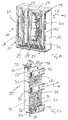
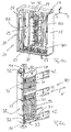
Figures 1a ,1b ,1c and1d show details of a fiber optic distribution device designed as a street cabinet and of a fiber optic management unit positioned inside the fiber optic distribution device.Figures 2a ,2b ,2c ,2d and3a to 7 show details of a fiber optic management unit. - The fiber
optic distribution device 20 shown inFigure 1a ,1b ,1c ,1d comprises ahousing 21 defining aninterior space 22 of the fiberoptic distribution device 20. Thehousing 21 is provided by abottom wall 23, atop wall 24, aback wall 25,side walls 26 and a cover (not shown) hinged to one of theside walls 26 by hinges 70. The cover can be pivoted around avertical axis 69 defined by thehinges 70 allowing to open and close the fiberoptic distribution device 20. At least onefiber optic cable 27 can be inserted from the exterior into theinterior space 22 of thehousing 21 and passed out from theinterior space 22 of thehousing 21 to the exterior. The or eachfiber optic cable 27 can be inserted into theinterior space 22 and passed out from theinterior space 22 through openings (not shown) in thebottom wall 23 in vertical direction Z. The vertical direction Z runs in the direction of to the height of the fiberoptic distribution device 20. - The fiber
optic distribution device 20 comprises at least one modular fiberoptic management unit 30 mounted in thehousing 21 of the fiberoptic distribution device 20. Each fiberoptic management unit 30 is positioned between two vertical mounting bars 29 of thehousing 21. Each fiberoptic management unit 30 is mounted to one of said two vertical mounting bars 29 of thehousing 21 of the fiberoptic distribution device 20 using mountingbrackets 42 and horizontal mounting rails 31. - The mounting rails 31 allow the respective fiber
optic management unit 30 to be horizontally pulled out from theinterior space 22 of thehousing 21 or horizontally pushed into theinterior space 22 of thehousing 21 in a horizontal direction X. The horizontal direction X runs in the direction of to the depth of the fiberoptic distribution device 20. The remaining horizontal direction Y runs in the direction of to the width of the fiberoptic distribution device 20. - The respective fiber
optic management unit 30 comprises atop side 32, abottom side 33, two oppositelong sides 34 and two oppositenarrow sides 35. In a first orientation (seeFigures 1a, 2a ,1b, 2b ,1c, 2c ) of an upright position of the respective fiberoptic management unit 30, the oppositelong sides 34 of the respective fiberoptic management unit 30 run parallel to horizontal direction X. In a second orientation (seeFigures 1d, 2d ) of the upright position of the respective fiberoptic management unit 30, the oppositelong sides 34 of the respective fiberoptic management unit 30 run perpendicular to the horizontal direction X. - The mounting rails 31 used to mount the respective fiber
optic management unit 30 in thehousing 21 of the fiberoptic distribution device 20 run in horizontal direction X. The same allow the respective fiberoptic management unit 30 to be horizontally pulled out from theinterior space 22 of thehousing 21 and to be horizontally pushed into theinterior space 22 of thehousing 21 when the respective fiberoptic management unit 30 is in said first orientation of the upright position. -
Figures 1a, 2a ,1b, 2b show the respective fiberoptic management unit 30 in the pushed in upright position andFigure 1c, 2c shows the respective fiberoptic management unit 30 in the pulled out upright position. - At least one first mounting
rail 31 is attached to one of thelong sides 34 of the respective fiberoptic management unit 30. At least one second mountingrail 31 is attached to thebottom side 33 or to the lower end of saidlong side 34 of the respective fiberoptic management unit 30. In the shown embodiment two first mounting rails 31 are attached to one of thelong sides 34 and one second mountingrail 31 is attached also to saidlong side 34 of the respective fiberoptic management unit 30, namely to a lower end of saidlong side 34. - The respective fiber
optic management unit 30 being pulled out from theinterior space 22 of thehousing 21 can be pivoted around avertical rotation axis 36 from said first orientation (seeFigure 1c, 2c ) into said second orientation (seeFigure 1d, 2d ) and vice versa from said second orientation into said first orientation while maintaining the upright position of the same (see arrow inFigures 2c ,2d ). - Each of the mounting
rails 31 provides at the end at which the respective mountingrail 31 is attached to the long side 34 ahinge 37, namely the or each first mountingrail 31 provides afirst hinge 37 and the or each second mountingrail 31 provides asecond hinge 37. - The hinges 37 define the
vertical rotation axis 36 for pivoting the respective fiberoptic management unit 30 between the first orientation of the upright position and the second orientation of the upright position when the respective fiberoptic management unit 30 is pulled out from theinterior space 22 of thehousing 21. - The or each second mounting
rail 31 being attached to thebottom side 33 or to the lower end of thelong side 34 of the respective fiberoptic management unit 30 is useful to avoid a tilting of the respective fiberoptic management unit 30 around a horizontal axis when the same is pivoted around thevertical axis 36 from of the first orientation into said second orientation thereby maintaining the upright position of the respective fiberoptic management unit 30 in the second orientation of the same. - As mentioned above, the fiber
optic distribution device 20 comprises at least one modular fiberoptic management unit 30 mounted in thehousing 21. Each fiberoptic management unit 30 comprisesseveral modules - Each fiber
optic management unit 30 comprises acable entry module 38 for inserting at least one incoming fiber optic cable (not shown) from theinterior space 22 of thehousing 21 of the fiberoptic distribution device 20 into the respective fiberoptic management unit 30 and for passing out least one outgoing fiber optic cable (not shown) from the respective fiberoptic management unit 30 in theinterior space 22 of thehousing 21 of the fiberoptic distribution device 20. - The
cable entry module 38 provides an upper module or top module of the respective fiberoptic management unit 30. Thecable entry module 38 of the respective fiberoptic management unit 30 comprises aback wall 44 carryingstrain relief elements 45 andfiber guide elements 46, atop wall 47 carrying anover-length storage unit 48, and at least oneside wall 49. The incoming fiber optic cable (not shown) is insertable into the respective fiberoptic management unit 30 through theside wall 49. A firststrain relief element 45 provides strain relief for the incoming fiber optic cable (not shown), while a secondstrain relief element 45 provides strain relief for fiber bundles (not shown) furcated from the incoming fiber optic cable. Thefiber guide elements 46 guide the fiber bundles within thecable entry module 38. - The
over-length storage unit 48 positioned on top of thecable entry module 38, namely above thetop wall 47 of thecable entry module 38, serves for storing over-length of the or each outgoing fiber optic cable (not shown). Theover-length storage unit 48 of thecable entry module 38 comprises acurved side wall 51 acting as bent control means for the or each outgoing fiber optic cable. - Each fiber
optic management unit 30 comprises further at least onesplice module 39. The or eachsplice module 39 is positioned below thecable entry module 38. The or eachsplice module 39 comprisesseveral splice trays 52 for handling splice connections preferably between fibers of the or each incoming fiber optic cable and fibers of fiber optic pigtails (not shown). - In the shown embodiment, the fiber
optic management unit 30 comprises twosplice modules 39 each havingseveral splice trays 52, wherein the number ofseveral splice trays 52 of thesesplice module 39 can be identical or different. - Each
splice module 39 of the respective fiberoptic management unit 30 comprises aback wall 58 carrying thesplice trays 52 and hingedside walls 54. Eachside wall 54 is mounted to one side of theback wall 58 of therespective splice module 39 throughhinges 72, wherein eachside wall 54 can be pivoted around a vertical axis 55 (seeFigures 5a and 5b ) defined by therespective hinge 72 between a first position in which theside walls 54 run generally perpendicular (seeFigure 5a ) to theback wall 58 and a second position in which theside walls 54 run generally parallel (seeFigure 5b ) to theback wall 58. This provides excellent access to thesplice trays 52 in the field. - At least one of said hinged side walls 54 (see
Figure 5b ) provides over-length storage for the or each outgoing fiber optic cable. In the shown embodiment, one hingedside wall 54 serves as anover-length storage unit 28 for the or each outgoing fiber optic cable. - Preferably, each fiber
optic management unit 30 comprises further at least onepatch module 40. The or eachpatch module 40 is positioned below the or eachsplice module 39. The or eachpatch module 40 comprises apatch field 56 having severalfiber optic adapters 57 for handling patch connections between fibers of the fiber optic pigtails (not shown) and fibers of the or each outgoing fiber optic cable (not shown). - Each
patch module 40 of the respective fiberoptic management unit 30 comprises aback wall 59 carrying thepatch field 56 and thereby thefiber optic adapters 57,strain relief elements 60,fiber guide elements 61 andover-length storage elements 73. Thestrain relief elements 60 provide strain relief for the fiber optic pigtails (not shown) running between thesplice trays 52 of therespective splice module 39 and the patch filed 56 of therespective patch module 40. Thefiber guide elements 61 guide the fiber optic pigtails in the region of therespective patch module 40. Eachpatch module 40 of the respective fiberoptic management unit 30 comprises further at least oneside wall 62. - In the shown embodiment, the fiber
optic management unit 30 comprises further aWDM module 41 positioned below the or each splice module and the or eachpatch module 40. TheWDM module 41 comprises a wavedivision multiplexing filter 63. TheWDM module 41 comprises aback wall 65 carrying the wavedivision multiplexing filter 63 andfiber guide elements 71. Theguide elements 71 can be used over over-length storage. TheWDM module 41 further comprises at least oneside wall 64. - In the shown embodiment, the
entry module 38, thepatch module 40 and theWDM module 41 each comprise oneside wall back wall respective module modules side wall optic management unit 30. Thesplice modules 39 each comprise two hingedside walls 54. - When the
modules optic management unit 30 are stacked above each other,adjacent modules back walls - This connection can be accomplished by screwing the
back walls adjacent modules back walls adjacent modules - Each fiber
optic management unit 30 further comprises acover 66 withventilation openings 67, thecover 66 being pivotable around a vertical rotation axis 68. - Each fiber
optic management unit 30 can be pre-configured in the plant according the customer requests or will consist at least of acable entry module 38 and asplice module 39 as starter configuration. Preferably, the starter configuration of the fiberoptic management unit 30 comprises further apatch module 40. - The field installer will mount the mounting
rails 31 providing the slide-out/slide-in functionality, which are part of the respective fiberoptic management unit 30, with the universal mounting bars 29 inside the fiberoptic distribution device 20. - The
fiber optic cables 27 are be guided from thebottom wall 23 of the in the fiberoptic distribution device 20 to the fiberoptic management units 30. - For best access to the fibers and fiber connections the fiber
optic management units 30 will slide in horizontal direction X out of theinterior space 22 of the housing of the fiberoptic distribution device 20 and will be pivoted around theaxis 36. - The fibers will be routed to the
splice trays 52. To improve accessibility theside walls 54 of thesplice modules 39 are hinged and can be opened. - The fibers of the incoming cable will be spliced to an outgoing cable or to the pigtails. In case of pigtails, the pigtails will be guided to the
patch module 40. On thepatch module 40 an integrated over length storage will handle the pigtail over length and guide the pigtails to theadapters 57 where theincoming cable 42 will be connected to the outgoing cables. - From the
patch module 40 the outgoing cables will be guided back to thesplice module 39 using one of the hingedside walls 54 as over-length storage. Theover-length storage tray 48 compensates the length differences due to the slide out function. - After installation, the
protective cover 66 will be closed. The closing will be done by fast locking levers. Then the fiberoptic management unit 30 will be slide back into the final park position within theinterior space 22 of the housing of the fiberoptic distribution device 20. -
- 20
- fiber optic distribution device
- 21
- housing
- 22
- interior space
- 23
- bottom wall
- 24
- top wall
- 25
- back wall
- 26
- side wall
- 27
- fiber optic cable
- 28
- over-length storage unit
- 29
- mounting bar
- 30
- fiber optic management unit
- 31
- mounting rail
- 32
- top side
- 33
- bottom side
- 34
- long side
- 35
- narrow side
- 36
- vertical axis
- 37
- hinge
- 38
- cable entry module
- 39
- splice module
- 40
- patch module
- 41
- WDM module
- 42
- mounting bracket
- 44
- back wall
- 45
- strain relief element
- 46
- fiber guide element
- 47
- top wall
- 48
- over-length storage tray
- 49
- side wall
- 50
- fiber bundle
- 51
- side wall
- 52
- splice tray
- 54
- side wall
- 55
- vertical axis
- 56
- patch field
- 57
- fiber optic adapters
- 58
- back wall
- 59
- back wall
- 60
- strain relief element
- 61
- fiber guide element
- 62
- side wall
- 63
- wave division multiplexing filter
- 64
- side wall
- 65
- back wall
- 66
- cover
- 67
- ventilation openings
- 68
- vertical axis
- 69
- vertical axis
- 70
- hinge
- 71
- fiber guide element
- 72
- hinge
- 73
- over-length storage element
Claims (13)
- A fiber optic distribution device (20), comprising:a housing (21) defining an interior space (22) of the fiber optic distribution device (20), wherein at least one fiber optic cable (27) can be inserted from an exterior into the interior space (22) of the housing (21) and passed out from the interior space (22) of the housing (21) in the exterior; andat least one modular fiber optic management unit (30) mounted in the housing (21), wherein the or each modular fiber optic management unit (30) comprises several modules stacked above each other, namely at least
a cable entry module (38) for inserting at least one incoming fiber optic cable from the interior space (22) of the housing (21) into the respective fiber optic management unit (30) and for passing out least one outgoing fiber optic cable from the respective fiber optic management unit (30) in the interior space (22) of the housing,
at least one splice module (39) comprising several splice trays (52) for handling splice connections between fibers of the or each incoming fiber optic cable and fibers of fiber optic pigtails or fibers of the or each outgoing fiber optic cable,wherein the or each fiber optic management unit (30) is mounted in the housing (21) through mounting rails (31) in such a way that
the respective fiber optic management unit (30) having a first orientation in an upright position of the same can be horizontally pulled out from the interior space (22) of the housing (21) or horizontally pushed into the interior space (22) of the housing (21) in said first orientation,
the respective fiber optic management unit (30) being pulled out from the interior space (22) of the housing (21) can be pivoted around a vertical rotation axis (36) from said first orientation into a second orientation and vice versa from said second orientation into the first orientation while maintaining the upright position of the same. - The fiber optic distribution device of claim 1, characterized in that
the or each fiber optic management unit (30) comprises a top side (32), a bottom side (33), two opposite long sides (34) and two opposite narrow sides (35);
in the first orientation of the upright position of the respective fiber optic management unit (30) the opposite long sides (34) of the respective fiber optic management unit (30) run almost parallel to the mounting rails (31) and thereby almost parallel to the direction in which the respective fiber optic management unit (30) can be horizontally pulled out from the interior space (22) of the housing (21) or horizontally pushed into the interior space (22) of the housing (21),
in the second orientation of the upright position of the respective fiber optic management unit (30) the opposite long sides (34) of the respective fiber optic management unit (30) run almost perpendicular to the mounting rails (31). - The fiber optic distribution device of claim 2, characterized in that
at least one first mounting rail (31) is attached to one of the long sides (34) of the respective fiber optic management unit (30),
at least one second mounting rail (31) is attached to the bottom side (33) or to said long side (34) of the fiber optic management unit (30). - The fiber optic distribution device of one of claims 1 to 3, characterized in that the mounting rails (31) comprise hinges (37), wherein the hinges (37) provide the vertical rotation axis (36) for pivoting the respective fiber optic management unit (30) between the first orientation of the upright position and the second orientation of the upright position when the respective fiber optic management unit (30) is pulled out from the interior space (22) of the housing (21).
- The fiber optic distribution device of one of claims 1 to 4, characterized in that the or each modular fiber optic management unit (30) further comprises at least one patch module (40) comprising a patch field (56) having several fiber optic adapters (57) for handling patch connections between fibers of the fiber optic pigtails and fibers of the or each outgoing fiber optic cable.
- The fiber optic distribution device of claim 5, characterized in that the cable entry module (38) provides a top module of the respective fiber optic management unit (30), that the or each splice module (39) is positioned below the cable entry module (38), and that the or each patch module (40) is positioned below the or each splice module (39).
- The fiber optic distribution device of one of claims 1 to 6, characterized in that the cable entry module (38) of the respective fiber optic management unit (30) comprises an over-length storage unit (48) on top of the cable entry module (38) for storing over-length of the or each outgoing fiber optic cable.
- The fiber optic distribution device of claim 7, characterized in that characterized in that the over-length storage unit (48) comprises a curved side wall (51) acting as bent control means the or each outgoing fiber optic cable.
- The fiber optic distribution device of one of claims 1 to 8, characterized in that the or each splice module (39) comprises hinged side walls (54), and that at least one of said hinged side walls (54) serves as an over-length storage unit (28) for the or each outgoing fiber optic cable.
- The fiber optic distribution device of claim 5, 7 and 9, characterized in that
the cable entry module (38) of the respective fiber optic management unit (30) comprises a back wall (44) carrying strain relief elements (45) and fiber guide elements (46), a top wall (47) carrying the over-length storage unit (48), and at least one side wall (49);
the or each splice module (39) of the respective fiber optic management unit (30) comprises a back wall (58) carrying the splice trays (52), and the hinged side walls (54),
the or each patch module (40) of the respective fiber optic management unit (30) comprises a back wall (59) carrying the fiber optic adapters (57), strain relief elements (60) and fiber guide elements (61), and at least one side wall (62),
wherein the modules (38, 39, 40, 41) of the respective fiber optic management unit (30) being positioned above each other are connected at their back walls (44, 58, 59, 65). - The fiber optic distribution device of one of claims 1 to 10, characterized in that the respective fiber optic management unit (30) further comprises a WDM module (41) positioned below the or each splice module (39) comprising a wave division multiplexing filter (62).
- The fiber optic distribution device of claim 11, characterized in that the WDM module (41) comprises a back wall (65) carrying the wave division multiplexing filter (62) and fiber guide elements (71), and at least one side wall (64).
- The fiber optic distribution device of one of claims 1 to 12, characterized in that the respective fiber optic management unit (30) further comprises a cover (66) with ventilation openings (67) being pivotable around a vertical rotation axis (68).
Priority Applications (1)
| Application Number | Priority Date | Filing Date | Title |
|---|---|---|---|
| EP14163374.3A EP2927724B1 (en) | 2014-04-03 | 2014-04-03 | Fiber optic distribution device |
Applications Claiming Priority (1)
| Application Number | Priority Date | Filing Date | Title |
|---|---|---|---|
| EP14163374.3A EP2927724B1 (en) | 2014-04-03 | 2014-04-03 | Fiber optic distribution device |
Publications (2)
| Publication Number | Publication Date |
|---|---|
| EP2927724A1 true EP2927724A1 (en) | 2015-10-07 |
| EP2927724B1 EP2927724B1 (en) | 2017-02-08 |
Family
ID=50397055
Family Applications (1)
| Application Number | Title | Priority Date | Filing Date |
|---|---|---|---|
| EP14163374.3A Not-in-force EP2927724B1 (en) | 2014-04-03 | 2014-04-03 | Fiber optic distribution device |
Country Status (1)
| Country | Link |
|---|---|
| EP (1) | EP2927724B1 (en) |
Cited By (7)
| Publication number | Priority date | Publication date | Assignee | Title |
|---|---|---|---|---|
| US10578823B2 (en) | 2017-12-28 | 2020-03-03 | Afl Ig Llc | Wall cabinets and fiber management trays |
| FR3108708A1 (en) * | 2020-03-27 | 2021-10-01 | Omelcom | Optical box comprising a storage element for optical fibers |
| CN116075761A (en) * | 2020-09-17 | 2023-05-05 | 泛达公司 | Optical distribution and splicing frame including box |
| CN117724216A (en) * | 2023-12-29 | 2024-03-19 | 烽火通信科技股份有限公司 | A kind of miniaturized optical cable transfer box |
| US20240094494A1 (en) * | 2021-05-20 | 2024-03-21 | Commscope Technologies Llc | Cabinet with sliding component mount |
| WO2024107586A3 (en) * | 2022-11-15 | 2024-06-27 | Afl Telecommunications Llc | Telecommunications rack and method for routing |
| WO2024166486A1 (en) * | 2023-02-08 | 2024-08-15 | 株式会社フジクラ | Optical cabinet |
Families Citing this family (1)
| Publication number | Priority date | Publication date | Assignee | Title |
|---|---|---|---|---|
| WO2025212720A1 (en) * | 2024-04-02 | 2025-10-09 | Afl Telecommunications Llc | Point of connection backboard assembly for telecommunications equipment |
Citations (6)
| Publication number | Priority date | Publication date | Assignee | Title |
|---|---|---|---|---|
| DE202005019319U1 (en) | 2005-12-08 | 2006-02-16 | CCS Technology, Inc., Wilmington | Built-in element for a cable distributor housing |
| US20070189691A1 (en) * | 2006-02-13 | 2007-08-16 | Michael Barth | Fiber distribution hub with swing frame and modular termination panels |
| US20080310810A1 (en) * | 2007-06-17 | 2008-12-18 | Telect, Inc. | Expandable fiber management |
| US20110285265A1 (en) * | 2006-10-02 | 2011-11-24 | Adc Telecommunications, Inc. | Fiber distribution hub with dual swing frames |
| WO2012106447A2 (en) * | 2011-02-01 | 2012-08-09 | K R Suresh Nair | Fiber distribution hubs |
| EP2629128A1 (en) * | 2012-02-14 | 2013-08-21 | CCS Technology, Inc. | Fiber optic distribution device |
-
2014
- 2014-04-03 EP EP14163374.3A patent/EP2927724B1/en not_active Not-in-force
Patent Citations (6)
| Publication number | Priority date | Publication date | Assignee | Title |
|---|---|---|---|---|
| DE202005019319U1 (en) | 2005-12-08 | 2006-02-16 | CCS Technology, Inc., Wilmington | Built-in element for a cable distributor housing |
| US20070189691A1 (en) * | 2006-02-13 | 2007-08-16 | Michael Barth | Fiber distribution hub with swing frame and modular termination panels |
| US20110285265A1 (en) * | 2006-10-02 | 2011-11-24 | Adc Telecommunications, Inc. | Fiber distribution hub with dual swing frames |
| US20080310810A1 (en) * | 2007-06-17 | 2008-12-18 | Telect, Inc. | Expandable fiber management |
| WO2012106447A2 (en) * | 2011-02-01 | 2012-08-09 | K R Suresh Nair | Fiber distribution hubs |
| EP2629128A1 (en) * | 2012-02-14 | 2013-08-21 | CCS Technology, Inc. | Fiber optic distribution device |
Cited By (7)
| Publication number | Priority date | Publication date | Assignee | Title |
|---|---|---|---|---|
| US10578823B2 (en) | 2017-12-28 | 2020-03-03 | Afl Ig Llc | Wall cabinets and fiber management trays |
| FR3108708A1 (en) * | 2020-03-27 | 2021-10-01 | Omelcom | Optical box comprising a storage element for optical fibers |
| CN116075761A (en) * | 2020-09-17 | 2023-05-05 | 泛达公司 | Optical distribution and splicing frame including box |
| US20240094494A1 (en) * | 2021-05-20 | 2024-03-21 | Commscope Technologies Llc | Cabinet with sliding component mount |
| WO2024107586A3 (en) * | 2022-11-15 | 2024-06-27 | Afl Telecommunications Llc | Telecommunications rack and method for routing |
| WO2024166486A1 (en) * | 2023-02-08 | 2024-08-15 | 株式会社フジクラ | Optical cabinet |
| CN117724216A (en) * | 2023-12-29 | 2024-03-19 | 烽火通信科技股份有限公司 | A kind of miniaturized optical cable transfer box |
Also Published As
| Publication number | Publication date |
|---|---|
| EP2927724B1 (en) | 2017-02-08 |
Similar Documents
| Publication | Publication Date | Title |
|---|---|---|
| EP2927724B1 (en) | Fiber optic distribution device | |
| US11614594B2 (en) | Optical fiber distribution system | |
| EP2508928B1 (en) | Enclosure for telecommunications cables, with removable organizer | |
| CN100589003C (en) | Framework for fiber distribution and management and related methods | |
| EP3195034B1 (en) | Multi-positionable telecommunications tray | |
| CN109541766B (en) | Telecommunications enclosure and organizer | |
| EP3195035B1 (en) | Telecommunications tray with a cable routing path extending through a pivot hinge | |
| US20160077296A1 (en) | Fiber optic enclosure for retrofitting pedestals in the field | |
| US7715682B2 (en) | Fiber distribution hub having an adjustable plate | |
| US10502914B2 (en) | Stackable telecommunication cabinet construction | |
| WO2019160672A1 (en) | Rack-mountable fiber optic splice enclosure | |
| EP2538255B1 (en) | Cable coupling device with overlength storage for jumper cables | |
| WO2016012873A1 (en) | Distribution container for optical fibres | |
| EP2521234A1 (en) | Wall mounted plate with integrated ducts | |
| WO1999047960A1 (en) | Optical fibre overlength storage | |
| HK1100976B (en) | Frame for optical fiber distribution and management, and associated methods |
Legal Events
| Date | Code | Title | Description |
|---|---|---|---|
| PUAI | Public reference made under article 153(3) epc to a published international application that has entered the european phase |
Free format text: ORIGINAL CODE: 0009012 |
|
| AK | Designated contracting states |
Kind code of ref document: A1 Designated state(s): AL AT BE BG CH CY CZ DE DK EE ES FI FR GB GR HR HU IE IS IT LI LT LU LV MC MK MT NL NO PL PT RO RS SE SI SK SM TR |
|
| AX | Request for extension of the european patent |
Extension state: BA ME |
|
| 17P | Request for examination filed |
Effective date: 20160407 |
|
| RBV | Designated contracting states (corrected) |
Designated state(s): AL AT BE BG CH CY CZ DE DK EE ES FI FR GB GR HR HU IE IS IT LI LT LU LV MC MK MT NL NO PL PT RO RS SE SI SK SM TR |
|
| GRAP | Despatch of communication of intention to grant a patent |
Free format text: ORIGINAL CODE: EPIDOSNIGR1 |
|
| INTG | Intention to grant announced |
Effective date: 20160719 |
|
| GRAS | Grant fee paid |
Free format text: ORIGINAL CODE: EPIDOSNIGR3 |
|
| GRAJ | Information related to disapproval of communication of intention to grant by the applicant or resumption of examination proceedings by the epo deleted |
Free format text: ORIGINAL CODE: EPIDOSDIGR1 |
|
| GRAL | Information related to payment of fee for publishing/printing deleted |
Free format text: ORIGINAL CODE: EPIDOSDIGR3 |
|
| GRAP | Despatch of communication of intention to grant a patent |
Free format text: ORIGINAL CODE: EPIDOSNIGR1 |
|
| INTC | Intention to grant announced (deleted) | ||
| GRAA | (expected) grant |
Free format text: ORIGINAL CODE: 0009210 |
|
| INTG | Intention to grant announced |
Effective date: 20161221 |
|
| AK | Designated contracting states |
Kind code of ref document: B1 Designated state(s): AL AT BE BG CH CY CZ DE DK EE ES FI FR GB GR HR HU IE IS IT LI LT LU LV MC MK MT NL NO PL PT RO RS SE SI SK SM TR |
|
| REG | Reference to a national code |
Ref country code: GB Ref legal event code: FG4D |
|
| RIN1 | Information on inventor provided before grant (corrected) |
Inventor name: MALOLEPSZY, BARTOSZ Inventor name: MUELLER, MICHAEL Inventor name: MUELLER, THORSTEN Inventor name: FABRYKOWSKI, GRZEGORZ Inventor name: SCHREIBER, SEBASTIAN Inventor name: STRUNCK, SVEN Inventor name: JEDRZEJKA, KAMIL |
|
| REG | Reference to a national code |
Ref country code: CH Ref legal event code: EP Ref country code: AT Ref legal event code: REF Ref document number: 867117 Country of ref document: AT Kind code of ref document: T Effective date: 20170215 |
|
| REG | Reference to a national code |
Ref country code: IE Ref legal event code: FG4D |
|
| REG | Reference to a national code |
Ref country code: DE Ref legal event code: R096 Ref document number: 602014006677 Country of ref document: DE |
|
| REG | Reference to a national code |
Ref country code: FR Ref legal event code: PLFP Year of fee payment: 4 |
|
| REG | Reference to a national code |
Ref country code: LT Ref legal event code: MG4D |
|
| REG | Reference to a national code |
Ref country code: NL Ref legal event code: MP Effective date: 20170208 |
|
| REG | Reference to a national code |
Ref country code: AT Ref legal event code: MK05 Ref document number: 867117 Country of ref document: AT Kind code of ref document: T Effective date: 20170208 |
|
| PG25 | Lapsed in a contracting state [announced via postgrant information from national office to epo] |
Ref country code: HR Free format text: LAPSE BECAUSE OF FAILURE TO SUBMIT A TRANSLATION OF THE DESCRIPTION OR TO PAY THE FEE WITHIN THE PRESCRIBED TIME-LIMIT Effective date: 20170208 Ref country code: FI Free format text: LAPSE BECAUSE OF FAILURE TO SUBMIT A TRANSLATION OF THE DESCRIPTION OR TO PAY THE FEE WITHIN THE PRESCRIBED TIME-LIMIT Effective date: 20170208 Ref country code: GR Free format text: LAPSE BECAUSE OF FAILURE TO SUBMIT A TRANSLATION OF THE DESCRIPTION OR TO PAY THE FEE WITHIN THE PRESCRIBED TIME-LIMIT Effective date: 20170509 Ref country code: LT Free format text: LAPSE BECAUSE OF FAILURE TO SUBMIT A TRANSLATION OF THE DESCRIPTION OR TO PAY THE FEE WITHIN THE PRESCRIBED TIME-LIMIT Effective date: 20170208 Ref country code: NO Free format text: LAPSE BECAUSE OF FAILURE TO SUBMIT A TRANSLATION OF THE DESCRIPTION OR TO PAY THE FEE WITHIN THE PRESCRIBED TIME-LIMIT Effective date: 20170508 |
|
| PG25 | Lapsed in a contracting state [announced via postgrant information from national office to epo] |
Ref country code: PT Free format text: LAPSE BECAUSE OF FAILURE TO SUBMIT A TRANSLATION OF THE DESCRIPTION OR TO PAY THE FEE WITHIN THE PRESCRIBED TIME-LIMIT Effective date: 20170608 Ref country code: ES Free format text: LAPSE BECAUSE OF FAILURE TO SUBMIT A TRANSLATION OF THE DESCRIPTION OR TO PAY THE FEE WITHIN THE PRESCRIBED TIME-LIMIT Effective date: 20170208 Ref country code: BG Free format text: LAPSE BECAUSE OF FAILURE TO SUBMIT A TRANSLATION OF THE DESCRIPTION OR TO PAY THE FEE WITHIN THE PRESCRIBED TIME-LIMIT Effective date: 20170508 Ref country code: NL Free format text: LAPSE BECAUSE OF NON-PAYMENT OF DUE FEES Effective date: 20170208 Ref country code: SE Free format text: LAPSE BECAUSE OF FAILURE TO SUBMIT A TRANSLATION OF THE DESCRIPTION OR TO PAY THE FEE WITHIN THE PRESCRIBED TIME-LIMIT Effective date: 20170208 Ref country code: LV Free format text: LAPSE BECAUSE OF FAILURE TO SUBMIT A TRANSLATION OF THE DESCRIPTION OR TO PAY THE FEE WITHIN THE PRESCRIBED TIME-LIMIT Effective date: 20170208 Ref country code: AT Free format text: LAPSE BECAUSE OF FAILURE TO SUBMIT A TRANSLATION OF THE DESCRIPTION OR TO PAY THE FEE WITHIN THE PRESCRIBED TIME-LIMIT Effective date: 20170208 Ref country code: RS Free format text: LAPSE BECAUSE OF FAILURE TO SUBMIT A TRANSLATION OF THE DESCRIPTION OR TO PAY THE FEE WITHIN THE PRESCRIBED TIME-LIMIT Effective date: 20170208 |
|
| PG25 | Lapsed in a contracting state [announced via postgrant information from national office to epo] |
Ref country code: EE Free format text: LAPSE BECAUSE OF FAILURE TO SUBMIT A TRANSLATION OF THE DESCRIPTION OR TO PAY THE FEE WITHIN THE PRESCRIBED TIME-LIMIT Effective date: 20170208 Ref country code: IT Free format text: LAPSE BECAUSE OF FAILURE TO SUBMIT A TRANSLATION OF THE DESCRIPTION OR TO PAY THE FEE WITHIN THE PRESCRIBED TIME-LIMIT Effective date: 20170208 Ref country code: SK Free format text: LAPSE BECAUSE OF FAILURE TO SUBMIT A TRANSLATION OF THE DESCRIPTION OR TO PAY THE FEE WITHIN THE PRESCRIBED TIME-LIMIT Effective date: 20170208 Ref country code: RO Free format text: LAPSE BECAUSE OF FAILURE TO SUBMIT A TRANSLATION OF THE DESCRIPTION OR TO PAY THE FEE WITHIN THE PRESCRIBED TIME-LIMIT Effective date: 20170208 Ref country code: CZ Free format text: LAPSE BECAUSE OF FAILURE TO SUBMIT A TRANSLATION OF THE DESCRIPTION OR TO PAY THE FEE WITHIN THE PRESCRIBED TIME-LIMIT Effective date: 20170208 |
|
| REG | Reference to a national code |
Ref country code: DE Ref legal event code: R097 Ref document number: 602014006677 Country of ref document: DE |
|
| PG25 | Lapsed in a contracting state [announced via postgrant information from national office to epo] |
Ref country code: PL Free format text: LAPSE BECAUSE OF FAILURE TO SUBMIT A TRANSLATION OF THE DESCRIPTION OR TO PAY THE FEE WITHIN THE PRESCRIBED TIME-LIMIT Effective date: 20170208 Ref country code: DK Free format text: LAPSE BECAUSE OF FAILURE TO SUBMIT A TRANSLATION OF THE DESCRIPTION OR TO PAY THE FEE WITHIN THE PRESCRIBED TIME-LIMIT Effective date: 20170208 Ref country code: SM Free format text: LAPSE BECAUSE OF FAILURE TO SUBMIT A TRANSLATION OF THE DESCRIPTION OR TO PAY THE FEE WITHIN THE PRESCRIBED TIME-LIMIT Effective date: 20170208 |
|
| REG | Reference to a national code |
Ref country code: CH Ref legal event code: PL |
|
| PLBE | No opposition filed within time limit |
Free format text: ORIGINAL CODE: 0009261 |
|
| STAA | Information on the status of an ep patent application or granted ep patent |
Free format text: STATUS: NO OPPOSITION FILED WITHIN TIME LIMIT |
|
| 26N | No opposition filed |
Effective date: 20171109 |
|
| REG | Reference to a national code |
Ref country code: IE Ref legal event code: MM4A |
|
| PG25 | Lapsed in a contracting state [announced via postgrant information from national office to epo] |
Ref country code: MC Free format text: LAPSE BECAUSE OF FAILURE TO SUBMIT A TRANSLATION OF THE DESCRIPTION OR TO PAY THE FEE WITHIN THE PRESCRIBED TIME-LIMIT Effective date: 20170208 |
|
| PG25 | Lapsed in a contracting state [announced via postgrant information from national office to epo] |
Ref country code: LU Free format text: LAPSE BECAUSE OF NON-PAYMENT OF DUE FEES Effective date: 20170403 Ref country code: SI Free format text: LAPSE BECAUSE OF FAILURE TO SUBMIT A TRANSLATION OF THE DESCRIPTION OR TO PAY THE FEE WITHIN THE PRESCRIBED TIME-LIMIT Effective date: 20170208 Ref country code: CH Free format text: LAPSE BECAUSE OF NON-PAYMENT OF DUE FEES Effective date: 20170430 Ref country code: LI Free format text: LAPSE BECAUSE OF NON-PAYMENT OF DUE FEES Effective date: 20170430 |
|
| REG | Reference to a national code |
Ref country code: FR Ref legal event code: PLFP Year of fee payment: 5 |
|
| REG | Reference to a national code |
Ref country code: BE Ref legal event code: MM Effective date: 20170430 |
|
| PG25 | Lapsed in a contracting state [announced via postgrant information from national office to epo] |
Ref country code: IE Free format text: LAPSE BECAUSE OF NON-PAYMENT OF DUE FEES Effective date: 20170403 |
|
| PG25 | Lapsed in a contracting state [announced via postgrant information from national office to epo] |
Ref country code: BE Free format text: LAPSE BECAUSE OF NON-PAYMENT OF DUE FEES Effective date: 20170430 |
|
| PG25 | Lapsed in a contracting state [announced via postgrant information from national office to epo] |
Ref country code: MT Free format text: LAPSE BECAUSE OF NON-PAYMENT OF DUE FEES Effective date: 20170403 |
|
| PG25 | Lapsed in a contracting state [announced via postgrant information from national office to epo] |
Ref country code: HU Free format text: LAPSE BECAUSE OF FAILURE TO SUBMIT A TRANSLATION OF THE DESCRIPTION OR TO PAY THE FEE WITHIN THE PRESCRIBED TIME-LIMIT; INVALID AB INITIO Effective date: 20140403 |
|
| PG25 | Lapsed in a contracting state [announced via postgrant information from national office to epo] |
Ref country code: CY Free format text: LAPSE BECAUSE OF FAILURE TO SUBMIT A TRANSLATION OF THE DESCRIPTION OR TO PAY THE FEE WITHIN THE PRESCRIBED TIME-LIMIT Effective date: 20170208 |
|
| PG25 | Lapsed in a contracting state [announced via postgrant information from national office to epo] |
Ref country code: MK Free format text: LAPSE BECAUSE OF FAILURE TO SUBMIT A TRANSLATION OF THE DESCRIPTION OR TO PAY THE FEE WITHIN THE PRESCRIBED TIME-LIMIT Effective date: 20170208 |
|
| PG25 | Lapsed in a contracting state [announced via postgrant information from national office to epo] |
Ref country code: TR Free format text: LAPSE BECAUSE OF FAILURE TO SUBMIT A TRANSLATION OF THE DESCRIPTION OR TO PAY THE FEE WITHIN THE PRESCRIBED TIME-LIMIT Effective date: 20170208 |
|
| PGFP | Annual fee paid to national office [announced via postgrant information from national office to epo] |
Ref country code: GB Payment date: 20200327 Year of fee payment: 7 |
|
| PGFP | Annual fee paid to national office [announced via postgrant information from national office to epo] |
Ref country code: FR Payment date: 20200320 Year of fee payment: 7 |
|
| PG25 | Lapsed in a contracting state [announced via postgrant information from national office to epo] |
Ref country code: AL Free format text: LAPSE BECAUSE OF FAILURE TO SUBMIT A TRANSLATION OF THE DESCRIPTION OR TO PAY THE FEE WITHIN THE PRESCRIBED TIME-LIMIT Effective date: 20170208 Ref country code: IS Free format text: LAPSE BECAUSE OF FAILURE TO SUBMIT A TRANSLATION OF THE DESCRIPTION OR TO PAY THE FEE WITHIN THE PRESCRIBED TIME-LIMIT Effective date: 20170608 |
|
| PGFP | Annual fee paid to national office [announced via postgrant information from national office to epo] |
Ref country code: DE Payment date: 20200317 Year of fee payment: 7 |
|
| REG | Reference to a national code |
Ref country code: DE Ref legal event code: R119 Ref document number: 602014006677 Country of ref document: DE |
|
| GBPC | Gb: european patent ceased through non-payment of renewal fee |
Effective date: 20210403 |
|
| PG25 | Lapsed in a contracting state [announced via postgrant information from national office to epo] |
Ref country code: GB Free format text: LAPSE BECAUSE OF NON-PAYMENT OF DUE FEES Effective date: 20210403 Ref country code: FR Free format text: LAPSE BECAUSE OF NON-PAYMENT OF DUE FEES Effective date: 20210430 Ref country code: DE Free format text: LAPSE BECAUSE OF NON-PAYMENT OF DUE FEES Effective date: 20211103 |