EP2927672A1 - Inspection method for welded joint - Google Patents
Inspection method for welded joint Download PDFInfo
- Publication number
- EP2927672A1 EP2927672A1 EP13859887.5A EP13859887A EP2927672A1 EP 2927672 A1 EP2927672 A1 EP 2927672A1 EP 13859887 A EP13859887 A EP 13859887A EP 2927672 A1 EP2927672 A1 EP 2927672A1
- Authority
- EP
- European Patent Office
- Prior art keywords
- recessed groove
- welded
- welded joint
- welding
- joint
- Prior art date
- Legal status (The legal status is an assumption and is not a legal conclusion. Google has not performed a legal analysis and makes no representation as to the accuracy of the status listed.)
- Granted
Links
Images



Classifications
-
- G—PHYSICS
- G01—MEASURING; TESTING
- G01N—INVESTIGATING OR ANALYSING MATERIALS BY DETERMINING THEIR CHEMICAL OR PHYSICAL PROPERTIES
- G01N23/00—Investigating or analysing materials by the use of wave or particle radiation, e.g. X-rays or neutrons, not covered by groups G01N3/00 – G01N17/00, G01N21/00 or G01N22/00
- G01N23/02—Investigating or analysing materials by the use of wave or particle radiation, e.g. X-rays or neutrons, not covered by groups G01N3/00 – G01N17/00, G01N21/00 or G01N22/00 by transmitting the radiation through the material
- G01N23/04—Investigating or analysing materials by the use of wave or particle radiation, e.g. X-rays or neutrons, not covered by groups G01N3/00 – G01N17/00, G01N21/00 or G01N22/00 by transmitting the radiation through the material and forming images of the material
-
- F—MECHANICAL ENGINEERING; LIGHTING; HEATING; WEAPONS; BLASTING
- F01—MACHINES OR ENGINES IN GENERAL; ENGINE PLANTS IN GENERAL; STEAM ENGINES
- F01D—NON-POSITIVE DISPLACEMENT MACHINES OR ENGINES, e.g. STEAM TURBINES
- F01D21/00—Shutting-down of machines or engines, e.g. in emergency; Regulating, controlling, or safety means not otherwise provided for
- F01D21/003—Arrangements for testing or measuring
-
- F—MECHANICAL ENGINEERING; LIGHTING; HEATING; WEAPONS; BLASTING
- F01—MACHINES OR ENGINES IN GENERAL; ENGINE PLANTS IN GENERAL; STEAM ENGINES
- F01D—NON-POSITIVE DISPLACEMENT MACHINES OR ENGINES, e.g. STEAM TURBINES
- F01D5/00—Blades; Blade-carrying members; Heating, heat-insulating, cooling or antivibration means on the blades or the members
- F01D5/02—Blade-carrying members, e.g. rotors
- F01D5/06—Rotors for more than one axial stage, e.g. of drum or multiple disc type; Details thereof, e.g. shafts, shaft connections
- F01D5/063—Welded rotors
-
- F—MECHANICAL ENGINEERING; LIGHTING; HEATING; WEAPONS; BLASTING
- F05—INDEXING SCHEMES RELATING TO ENGINES OR PUMPS IN VARIOUS SUBCLASSES OF CLASSES F01-F04
- F05D—INDEXING SCHEME FOR ASPECTS RELATING TO NON-POSITIVE-DISPLACEMENT MACHINES OR ENGINES, GAS-TURBINES OR JET-PROPULSION PLANTS
- F05D2230/00—Manufacture
- F05D2230/20—Manufacture essentially without removing material
- F05D2230/23—Manufacture essentially without removing material by permanently joining parts together
- F05D2230/232—Manufacture essentially without removing material by permanently joining parts together by welding
-
- F—MECHANICAL ENGINEERING; LIGHTING; HEATING; WEAPONS; BLASTING
- F05—INDEXING SCHEMES RELATING TO ENGINES OR PUMPS IN VARIOUS SUBCLASSES OF CLASSES F01-F04
- F05D—INDEXING SCHEME FOR ASPECTS RELATING TO NON-POSITIVE-DISPLACEMENT MACHINES OR ENGINES, GAS-TURBINES OR JET-PROPULSION PLANTS
- F05D2260/00—Function
- F05D2260/80—Diagnostics
-
- F—MECHANICAL ENGINEERING; LIGHTING; HEATING; WEAPONS; BLASTING
- F05—INDEXING SCHEMES RELATING TO ENGINES OR PUMPS IN VARIOUS SUBCLASSES OF CLASSES F01-F04
- F05D—INDEXING SCHEME FOR ASPECTS RELATING TO NON-POSITIVE-DISPLACEMENT MACHINES OR ENGINES, GAS-TURBINES OR JET-PROPULSION PLANTS
- F05D2300/00—Materials; Properties thereof
- F05D2300/10—Metals, alloys or intermetallic compounds
- F05D2300/17—Alloys
- F05D2300/171—Steel alloys
-
- G—PHYSICS
- G01—MEASURING; TESTING
- G01N—INVESTIGATING OR ANALYSING MATERIALS BY DETERMINING THEIR CHEMICAL OR PHYSICAL PROPERTIES
- G01N2223/00—Investigating materials by wave or particle radiation
- G01N2223/60—Specific applications or type of materials
- G01N2223/629—Specific applications or type of materials welds, bonds, sealing compounds
Definitions
- the present invention relates to a method of non-destructively inspecting a welded joint for incomplete penetration using radiation.
- a high-temperature section subjected to high temperature steam is made of material different from a low-temperature section subjected to low temperature steam so that each section is made of material appropriate for its environment and the sections are connected to each other by welding.
- the high-temperature section is made of high heat resisting steel
- the low-temperature section is made of low alloy steel.
- FIG.8 illustrates a common structure of a steam turbine. In FIG.
- the steam turbine 1 is configured such that a plurality of split hollow disks 7 are fitted together between split hollow disks 5 having support shafts 3 and cylindrical ends and that abutment portions of adjacent two of the split hollow disks 5, 7 are connected at a welded joint part W. In this manner, in the steam turbine 1 manufactured by welding the split hollow disks 5, 7 together, it is important to inspect a welding state of the welded joint part W. Further, as illustrated in FIG.1 , the steam turbine 1 has an interior space I formed therein.
- FIG.9A and FIG.9B illustrate a welding method of related art for the welded joint part W.
- the base metal 100 and the base metal 200 constitute the hollow disks that are made of different materials and on joint surfaces of the base metals 100, 200, groove parts 102, 202 and abutment faces 104, 204 are respectively formed.
- the groove parts 102, 202 are formed on a side that faces an exterior space O and the abutment faces 104, 204 are formed on a side facing the interior space I.
- a welding torch 300 is positioned between the groove part 102 and the groove part 202 from the exterior space O.
- the abutment faces 104, 204 are melted together and also build-up welding is performed on the groove parts 102, 202 one pass at a time using the welding torch 300.
- a penetration part M formed between the abutment faces 104, 204 needs to be inspected for lack of penetration.
- the penetration part M cannot be visually checked from the exterior space O.
- an inspection hole 106 is formed in the base metal 100 (or the base metal 200) to insert a borescope (not shown) into the interior space I through the inspection hole 106 from the exterior space O in the direction of arrow a.
- the borescope is inserted toward the penetration part M from the interior space I in the axial direction of the interior space I (direction of arrow b). Then, using the borescope, the penetration part M is visually checked for complete penetration. This visual inspection is preferably performed immediately after welding the first pass (a root pass) to make it easier to repair the part in case that lack of penetration is found.
- Patent Literature 1 It is described in Patent Literature 1 to perform the above inspection on the welded joint part of a steam turbine rotor. Further, Patent Literature 1 also describes that an X-ray source is inserted into the interior space I through the inspection hole and then a radiographic test of the welded joint part is carried out to inspect the welding state of the welded joint part. Further, it is described in Patent Literature 2 to visually monitor the welding part, in the case of welding a rotor of a steam turbine or the like, by means of a video system integrated in a welding torch.
- Patent Literature 3 describes that in the case of welding the steam turbine rotor or the like, the joint surface is formed with a groove and an abutment face and the abutment faces have complementary shapes to form a protrusion and a recess for orienting the joint surfaces of two base metal pieces.
- the inspection hole or the interior space I so that the borescope can be inserted to the welded joint part W from the exterior space O.
- the interior space I does not always exist.
- the strength of the base metal is deteriorated and thus, structural design taking into account the strength of the base metal around the inspection hole is required.
- foreign objects such as steam enter the base metal through the inspection hole, which may affect operation of a device such as a steam turbine formed by the base metals.
- the remaining state of the abutment face is checked using a radiographic image projected on a photosensitive film. Based on this, it is checked whether or not penetration of the abutment face is incomplete.
- the abutment face is hard to form an image on the photosensitive film.
- the image captured on the photosensitive film is of the part disposed on the side farther from an X-ray generator and thus it is difficult to check presence or absence of the abutment face based on the image on the photosensitive film.
- an object of the present invention to attain an inspection method for a welded joint, which enables inspection of the abutment face disposed where it cannot be visually inspected, without making an inspection hole in the base metal.
- an inspection method for a welded joint is an inspection method for a welded joint formed between a pair of base metals with a groove part and an abutment face being formed on a joint surface between the pair of base metals.
- the inspection method comprises steps of:
- the recessed groove is formed in advance and the step of irradiating the joint surface is performed after welding. Then, presence or absence of the recessed groove is determined based on the image formed on the photosensitive film. The presence or absence of the recessed groove can be clearly confirmed, unlike the abutment face. If the recessed groove is confirmed, it is determined there is incomplete penetration. If the recessed groove is not confirmed, it is determined that the abutment faces are penetrated. As a result, it is no longer necessary to provide the inspection hole and the above-mentioned issues regarding the inspection hole can be solved. Further, the irradiation step may be performed immediately after welding the first pass (a root pass) so that it is easier to repair the part in case that incomplete penetration is found.
- the recessed groove preferably has a cross section area whose dimension has a lower limit so that the recessed groove is distinguishable using the image obtained in the determining step and an upper limit so that the recessed groove is fillable with the at least one pass of build-up welding.
- a shape of the recessed groove in cross section may be arc, preferably rectangular, so that the image obtained by irradiation can be clearly formed on the film.
- the recessed groove has, for example, an opening width of 0.3mm or more to 0.5mm or less and a depth of 0.2mm or more to 1.0mm or less to satisfy the above conditions.
- the recessed groove is formed preferably on the joint surface of only one of the pair of base metals. This makes it easier to form the recessed groove.
- a protrusion and a recess are preferably formed adjacent to the recessed groove, the protrusion and the recess being configured to complementarily fit to each other. This makes it easier to position the joint surfaces of the pair of base materials with respect to each other.
- the pair of base metals has a hollow cylindrical shape and are welded to each other in an axial direction via the joint surfaces
- presence or absence of incomplete penetration in the abutment face formed facing the interior space of a hollow cylindrical shape can be inspected without making the inspection hole.
- a welded rotor for a turbine which is formed by the hollow cylindrical bodies welded to one another in the axial direction via the joint surfaces
- presence or absence of incomplete penetration in the abutment face formed in the joint surface can be inspected without making the inspection hole.
- the present invention it is possible to check presence or absence of incomplete penetration in the abutment faces of the welded joint surfaces where they cannot be visually checked directly, without making the inspection hole in the base metal. This saves extra work for making the inspection hole and also prevents decline in strength of the base metal. Further, the interior space of the base metal is maintained tightly sealed.
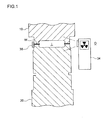
- FIG.1 illustrates the state where split hollow disks 10, 20 forming a steam turbine rotor are welded together at a welded joint part W.
- the steam turbine rotor is formed by a plurality of split hollow disks including the split hollow disks 10, 20 that are welded together in the axial direction.
- Inside the welded joint part W an interior space I is formed.
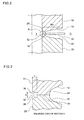
- FIG.2 and FIG.3 show a joint surface Wc before welding.
- the joint surface Wc has groove parts 12, 22 formed on an exterior space O side and abutment faces 14, 24 formed on the interior space I side.
- the abutment faces 14, 24 contact with each other.
- a circular recessed groove 32 opening to the interior space I is formed at one end of the abutment faces 14, 24 in the circumferential direction of the split hollow disks 10, 20.
- the end of the abutment faces 14, 24 where the recessed groove 32 is formed is on an opposite side of the abutment faces 14, 24 from the groove parts 12, 22.
- the recessed groove 32 is formed by a rectangular notch 16 formed in the abutment face 14 of the split hollow disk 10 and another rectangular notch 26 formed in the abutment face 24 of the split hollow disk 20, that are disposed facing each other.
- the recessed groove 32 has a symmetrical shape with respect to the abutment faces 14, 24.
- the recessed groove 32 has an opening width X in the axial direction, X being 0.3mm to 0.5mm and a depth Y being 0.2mm to 1.0mm.
- the joint surface Wc is welded by placing a welding torch 30 in a groove formed by the groove parts 12, 22 from the exterior space O, directing the welding torch 30 toward the abutment faces 14, 24, and then rotating the split hollow disks 10, 20 in such a state that the split hollow disks 10, 20 are positioned with respect to each other.
- build-up welding is performed by the welding torch 30 on the groove formed by the groove parts 12, 22.
- a penetration part is formed in the abutment faces 14, 24 and the recessed groove 32 is filled.
- ten to twenty passes of build-up welding are performed to fill the groove formed by the groove parts 12, 22.
- an X-ray generator 34 is placed in the exterior space O to check presence or absence of incomplete penetration in the abutment faces 14, 24 as illustrated in FIG.1 . Further, a high-temperature film cassette 36 is attached to outer circumferential surfaces of the split hollow disks 10, 20 which are 180° out of phase with the X-ray generator 34, at a position to extend over the welded joint part W.
- FIG.4 illustrates the configuration of the high-temperature film cassette 36.
- the high-temperature film cassette 36 includes a TeflonTM plate 38, a heat-insulating plate 40 made of heat insulating material, and a photosensitive film 42 on which radiation having passed through the welded joint part W is exposed.
- the TeflonTM plate 38, the heat-insulating plate 40 and the photosensitive film 42 are stacked in this order from a side nearer to the welded joint part W so as to form the high-temperature film cassette 36.
- the radiation penetrates the specimen and gradually weakens due to interaction with the specimen.
- the radiation penetrates well in a region with defects such as blowholes compared to a region without defects. As a result, the region with defects such as blowholes is detected as a dark image on the photosensitive film 42.
- X-rays are emitted toward the welded joint part W from the X-ray generator 34 and the photosensitive film 42 is exposed to the X-rays that have penetrated the welded joint part W to form an image on the photosensitive film 42.
- the image formed on the photosensitive film 42 is the welded joint part W on a side farther from the X-ray generator 34.
- the recessed groove 32 is shown on the photosensitive film 42 clearly as a dark image.
- the interior space I can be maintained airtight, so that steam can be prevented from entering the interior space I and affecting the operation of the steam turbine or deteriorating the operation efficiency.
- the cross section area of the recessed groove 32 is rectangular, a shape of the recessed groove 32 can be clearly formed on the photosensitive film 42.
- the image of the recessed groove 32 can be formed distinctly on the photosensitive film 42 and the recessed groove 32 can be surely filled with one pass of build-up welding.
- the welded joint part W is irradiated after one pass of build-up welding. This makes it easier to repair the part after confirming incomplete penetration.
- a circular recessed groove 44 opening to the interior space I is formed at one end of the abutment faces 14, 24 in the circumferential direction of the split hollow disks 10, 20.
- the end of the abutment faces 14, 24 where the recessed groove 44 is formed is on an opposite side of the abutment faces 14, 24 from the groove parts 12, 22.
- the recessed groove 44 is formed by arranging the split hollow disk 10 and a rectangular notch 46 formed only in the abutment face 24 of the split hollow disk 20 to face each other.
- the rest of the configuration is the same as that of the first embodiment.
- the recessed groove 44 can be formed by machining only the abutment face 24 and thus formation of the recessed groove 44 is easy.
- the recessed groove 44 opening to the interior space I is formed by arranging the split hollow disk 10 and the rectangular notch 46 formed only in the abutment face 24 of the split hollow disk 20 to face each other.
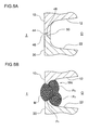
- a protrusion 48 and a protrusion 50 are formed adjacent to the recessed groove 44 behind the recessed groove 44 (the exterior space O side) in the abutment faces 24, 14 of the split hollow disks 20, 10, respectively.
- These protrusions 48, 50 have shapes to complementarily fit to each other.
- FIG.6B illustrates the joint surface Wc after the first pass P 1 , the second pass P 2 and the third pass P 3 of build-up welding are performed.
- the penetration part M is formed in the abutment faces to fill the recessed groove 44.
- FIG.7A is an image of the pre-welding joint part W captured on the photosensitive film 42.
- FIG.7B is an actual image of the welded joint part W captured on the photosensitive film 42 after the first pass of build-up welding is performed.
- the image S 44 of the recessed groove 44 is clearly shown.
- no image is formed on the photosensitive film 42 and thus it can be seen that the penetration part M is formed in the abutment faces and the recessed groove 44 is successfully filled.
- FIG.7C is an image of the joint part W shown as a comparison example.
- the welded joint part W is not formed with the recessed groove 44 and the image of the welded joint part W is formed on the photosensitive film 42.
- the line of the abutment face is vaguely confirmed. However, it is hard to distinguish from the rest. This makes it difficult to determine whether or not the penetration part M is formed normally after the first pass of build-up welding.
- the same function effects as the second embodiment can be obtained. Further, as the protrusions 48, 50 that complementarily fit to each other are formed in the abutment face of the split hollow disks 10, 20, sealing effect of the interior space I in the welded joint part W can be enhanced. Furthermore, as the protrusions 48, 50 are formed, it is made easier to position the split hollow disks 10, 20 with respect to each other when welding.
- inspection of the welded joint part can be performed on the abutment faces of the welded joint surfaces located where they cannot be visually inspected, without making an inspection hole in a base metal.
Landscapes
- Engineering & Computer Science (AREA)
- Biochemistry (AREA)
- Immunology (AREA)
- Physics & Mathematics (AREA)
- Health & Medical Sciences (AREA)
- Life Sciences & Earth Sciences (AREA)
- Chemical & Material Sciences (AREA)
- Pathology (AREA)
- General Health & Medical Sciences (AREA)
- Analytical Chemistry (AREA)
- General Physics & Mathematics (AREA)
- Mechanical Engineering (AREA)
- General Engineering & Computer Science (AREA)
- Butt Welding And Welding Of Specific Article (AREA)
- Analysing Materials By The Use Of Radiation (AREA)
- Turbine Rotor Nozzle Sealing (AREA)
Abstract
Description
- The present invention relates to a method of non-destructively inspecting a welded joint for incomplete penetration using radiation.
- In a rotor of a steam turbine, in association with the trend of using high temperature steam, a high-temperature section subjected to high temperature steam is made of material different from a low-temperature section subjected to low temperature steam so that each section is made of material appropriate for its environment and the sections are connected to each other by welding. For instance, the high-temperature section is made of high heat resisting steel, whereas the low-temperature section is made of low alloy steel.
FIG.8 illustrates a common structure of a steam turbine. InFIG. 8 , the steam turbine 1 is configured such that a plurality of split hollow disks 7 are fitted together between split hollow disks 5 having support shafts 3 and cylindrical ends and that abutment portions of adjacent two of the split hollow disks 5, 7 are connected at a welded joint part W. In this manner, in the steam turbine 1 manufactured by welding the split hollow disks 5, 7 together, it is important to inspect a welding state of the welded joint part W. Further, as illustrated inFIG.1 , the steam turbine 1 has an interior space I formed therein. -
FIG.9A and FIG.9B illustrate a welding method of related art for the welded joint part W. InFIG.9A , thebase metal 100 and thebase metal 200 constitute the hollow disks that are made of different materials and on joint surfaces of thebase metals groove parts abutment faces FIG.9A , thegroove parts abutment faces welding torch 300 is positioned between thegroove part 102 and thegroove part 202 from the exterior space O. - Next, as illustrated in
FIG.9B , the abutment faces 104, 204 are melted together and also build-up welding is performed on thegroove parts welding torch 300. After performing the build-up welding, a penetration part M formed between theabutment faces inspection hole 106 is formed in the base metal 100 (or the base metal 200) to insert a borescope (not shown) into the interior space I through theinspection hole 106 from the exterior space O in the direction of arrow a. If the penetration part M is accessible, the borescope is inserted toward the penetration part M from the interior space I in the axial direction of the interior space I (direction of arrow b). Then, using the borescope, the penetration part M is visually checked for complete penetration. This visual inspection is preferably performed immediately after welding the first pass (a root pass) to make it easier to repair the part in case that lack of penetration is found. - It is described in Patent Literature 1 to perform the above inspection on the welded joint part of a steam turbine rotor. Further, Patent Literature 1 also describes that an X-ray source is inserted into the interior space I through the inspection hole and then a radiographic test of the welded joint part is carried out to inspect the welding state of the welded joint part. Further, it is described in Patent Literature 2 to visually monitor the welding part, in the case of welding a rotor of a steam turbine or the like, by means of a video system integrated in a welding torch. Furthermore, Patent Literature 3 describes that in the case of welding the steam turbine rotor or the like, the joint surface is formed with a groove and an abutment face and the abutment faces have complementary shapes to form a protrusion and a recess for orienting the joint surfaces of two base metal pieces.
-
- [PTL 1]
JP 09-108883 A - [PTL 2]
JP 2010-201507 A - [PTL 3]
JP 2011-177790 A - In the inspection methods of the related art, it is necessary to form the inspection hole or the interior space I so that the borescope can be inserted to the welded joint part W from the exterior space O. However, the interior space I does not always exist. Also, by making the inspection hole in the base metal, the strength of the base metal is deteriorated and thus, structural design taking into account the strength of the base metal around the inspection hole is required. Further, there is a concern that foreign objects such as steam enter the base metal through the inspection hole, which may affect operation of a device such as a steam turbine formed by the base metals.
- As described in Patent Literature 1, in the radiographic test using the X-ray source inserted in the inspection hole, the remaining state of the abutment face is checked using a radiographic image projected on a photosensitive film. Based on this, it is checked whether or not penetration of the abutment face is incomplete. However, the abutment face is hard to form an image on the photosensitive film. Further, the image captured on the photosensitive film is of the part disposed on the side farther from an X-ray generator and thus it is difficult to check presence or absence of the abutment face based on the image on the photosensitive film.
- In view of the above issues of the related art, it is an object of the present invention to attain an inspection method for a welded joint, which enables inspection of the abutment face disposed where it cannot be visually inspected, without making an inspection hole in the base metal.
- To achieve the above object, an inspection method for a welded joint according to the present invention is an inspection method for a welded joint formed between a pair of base metals with a groove part and an abutment face being formed on a joint surface between the pair of base metals. The inspection method comprises steps of:
- forming a recessed groove opening to a surface of the base metal in advance at one end of the abutment face;
- irradiating the joint surface from a groove part formation side after at least one pass of build-up welding is performed on the groove part; and
- determining presence or absence of incomplete penetration in the welded joint based on an image formed on a photosensitive film by radiation penetrating the joint surface.
- In the present invention, the recessed groove is formed in advance and the step of irradiating the joint surface is performed after welding. Then, presence or absence of the recessed groove is determined based on the image formed on the photosensitive film. The presence or absence of the recessed groove can be clearly confirmed, unlike the abutment face. If the recessed groove is confirmed, it is determined there is incomplete penetration. If the recessed groove is not confirmed, it is determined that the abutment faces are penetrated. As a result, it is no longer necessary to provide the inspection hole and the above-mentioned issues regarding the inspection hole can be solved. Further, the irradiation step may be performed immediately after welding the first pass (a root pass) so that it is easier to repair the part in case that incomplete penetration is found.
- In the present invention, the recessed groove preferably has a cross section area whose dimension has a lower limit so that the recessed groove is distinguishable using the image obtained in the determining step and an upper limit so that the recessed groove is fillable with the at least one pass of build-up welding. As a result, presence or absence of the recessed groove after welding can be confirmed by irradiating the joint surface and the recessed groove can be filled by build-up welding. Therefore, the adverse effect on strength, etc. of the base metal can be eliminated.
- A shape of the recessed groove in cross section may be arc, preferably rectangular, so that the image obtained by irradiation can be clearly formed on the film. In the case where the recessed groove has a rectangular shape in cross section, the recessed groove has, for example, an opening width of 0.3mm or more to 0.5mm or less and a depth of 0.2mm or more to 1.0mm or less to satisfy the above conditions.
- In the present invention, the recessed groove is formed preferably on the joint surface of only one of the pair of base metals. This makes it easier to form the recessed groove. Further, on the joint surface, a protrusion and a recess are preferably formed adjacent to the recessed groove, the protrusion and the recess being configured to complementarily fit to each other. This makes it easier to position the joint surfaces of the pair of base materials with respect to each other.
- In such a case that the pair of base metals has a hollow cylindrical shape and are welded to each other in an axial direction via the joint surfaces, with application of the present invention to this, presence or absence of incomplete penetration in the abutment face formed facing the interior space of a hollow cylindrical shape can be inspected without making the inspection hole. For instance, by applying the present invention to a welded rotor for a turbine which is formed by the hollow cylindrical bodies welded to one another in the axial direction via the joint surfaces, presence or absence of incomplete penetration in the abutment face formed in the joint surface can be inspected without making the inspection hole.
- According to the present invention, it is possible to check presence or absence of incomplete penetration in the abutment faces of the welded joint surfaces where they cannot be visually checked directly, without making the inspection hole in the base metal. This saves extra work for making the inspection hole and also prevents decline in strength of the base metal. Further, the interior space of the base metal is maintained tightly sealed.
-
- [
FIG.1] FIG.1 is a cross-sectional view of a welded joint part in relation to a first embodiment of the present invention. - [
FIG.2] FIG.2 is an enlarged cross-sectional view of a part ofFIG.1 . - [
FIG.3] FIG.3 is an enlarged cross-sectional view of section A ofFIG.2 . - [
FIG.4] FIG.4 is a cross-sectional view of a photosensitive film used in the first embodiment. - [
FIG.5] FIG.5 is a cross-sectional view of a welded joint part in relation to a second embodiment of the present invention. - [
FIG.6A] FIG.6A is a cross-sectional view of a pre-welding joint surface which is the joint surface before welding in relation to a third embodiment of the present invention. - [
FIG.6B] FIG.6B is a cross-sectional view of a post-welding joint surface which is a joint surface after welding in relation to the third embodiment of the present invention. - [
FIG.7A] FIG.7A is an image of the pre-welding joint surface captured on a photosensitive film in relation to the third embodiment. - [
FIG.7B] FIG.7B is an image of the post-welding joint surface captured on the photosensitive film in relation to the third embodiment. - [
FIG.7C] FIG.7C is an image of a pre-welding joint surface in which a recessed groove is not formed (Comparison Example). - [
FIG.8] FIG.8 is a cross-sectional view of a steam turbine rotor taken from the front. - [
FIG.9A] FIG.9A is a cross-sectional view of a pre-welding joint surface according to a conventional welding method. - [
FIG.9B] FIG.9B is a cross-sectional view of a joint surface on which one pass is welded according to the conventional welding method. - The present invention will now be described in detail using embodiments shown in the accompanying drawings. It is intended, however, that unless particularly specified in these embodiments, dimensions, materials, and shapes of components, their relative positions and the like shall be interpreted as illustrative only and not limitative of the scope of the present invention.
- A first embodiment of the present invention is explained in reference to
FIG.1 to FIG.4 .FIG.1 illustrates the state where splithollow disks hollow disks FIG.2 and FIG.3 show a joint surface Wc before welding. - In
FIG.2 and FIG.3 , the joint surface Wc hasgroove parts - As illustrated in
FIG.3 , a circular recessedgroove 32 opening to the interior space I is formed at one end of the abutment faces 14, 24 in the circumferential direction of the splithollow disks groove 32 is formed is on an opposite side of the abutment faces 14, 24 from thegroove parts groove 32 is formed by arectangular notch 16 formed in theabutment face 14 of the splithollow disk 10 and anotherrectangular notch 26 formed in theabutment face 24 of the splithollow disk 20, that are disposed facing each other. The recessedgroove 32 has a symmetrical shape with respect to the abutment faces 14, 24. In this embodiment, the recessedgroove 32 has an opening width X in the axial direction, X being 0.3mm to 0.5mm and a depth Y being 0.2mm to 1.0mm. - As illustrated in
FIG.2 , the joint surface Wc is welded by placing awelding torch 30 in a groove formed by thegroove parts welding torch 30 toward the abutment faces 14, 24, and then rotating the splithollow disks hollow disks welding torch 30 on the groove formed by thegroove parts groove 32 is filled. Next, ten to twenty passes of build-up welding are performed to fill the groove formed by thegroove parts - After laying one pass, an
X-ray generator 34 is placed in the exterior space O to check presence or absence of incomplete penetration in the abutment faces 14, 24 as illustrated inFIG.1 . Further, a high-temperature film cassette 36 is attached to outer circumferential surfaces of the splithollow disks X-ray generator 34, at a position to extend over the welded joint part W. -
FIG.4 illustrates the configuration of the high-temperature film cassette 36. The high-temperature film cassette 36 includes aTeflon™ plate 38, a heat-insulatingplate 40 made of heat insulating material, and aphotosensitive film 42 on which radiation having passed through the welded joint part W is exposed. TheTeflon™ plate 38, the heat-insulatingplate 40 and thephotosensitive film 42 are stacked in this order from a side nearer to the welded joint part W so as to form the high-temperature film cassette 36. When irradiating a specimen, the radiation penetrates the specimen and gradually weakens due to interaction with the specimen. In the case of a welded part, the radiation penetrates well in a region with defects such as blowholes compared to a region without defects. As a result, the region with defects such as blowholes is detected as a dark image on thephotosensitive film 42. - In this configuration, X-rays are emitted toward the welded joint part W from the
X-ray generator 34 and thephotosensitive film 42 is exposed to the X-rays that have penetrated the welded joint part W to form an image on thephotosensitive film 42. The image formed on thephotosensitive film 42 is the welded joint part W on a side farther from theX-ray generator 34. Thus, if there is incomplete penetration in the abutment faces 14, 24, an image of the recessedgroove 32 is formed clearly on thephotosensitive film 42. - According to this embodiment, when there is incomplete penetration in the abutment faces 14, 24, the recessed
groove 32 is shown on thephotosensitive film 42 clearly as a dark image. Thus, it is possible to precisely acknowledge presence or absence of incomplete penetration in the abutment faces 14, 24. Therefore, it is no longer necessary to drill an inspection hole in the splithollow disks hollow disks - Further, the interior space I can be maintained airtight, so that steam can be prevented from entering the interior space I and affecting the operation of the steam turbine or deteriorating the operation efficiency. Further, as the cross section area of the recessed
groove 32 is rectangular, a shape of the recessedgroove 32 can be clearly formed on thephotosensitive film 42. Further, as the cross section area of the recessedgroove 32 has the above described dimensions, the image of the recessedgroove 32 can be formed distinctly on thephotosensitive film 42 and the recessedgroove 32 can be surely filled with one pass of build-up welding. Furthermore, the welded joint part W is irradiated after one pass of build-up welding. This makes it easier to repair the part after confirming incomplete penetration. - Next, a second embodiment of the present invention is explained in reference to
FIG 5 . In this embodiment, similarly to the first embodiment, a circular recessedgroove 44 opening to the interior space I is formed at one end of the abutment faces 14, 24 in the circumferential direction of the splithollow disks groove 44 is formed is on an opposite side of the abutment faces 14, 24 from thegroove parts groove 44 is formed by arranging the splithollow disk 10 and arectangular notch 46 formed only in theabutment face 24 of the splithollow disk 20 to face each other. The rest of the configuration is the same as that of the first embodiment. According to this embodiment, the recessedgroove 44 can be formed by machining only theabutment face 24 and thus formation of the recessedgroove 44 is easy. - Next, a third embodiment of the present invention is explained in reference to
FIG.6A, FIG.6B ,FIG.7A, FIG.7B, and FIG7C . In this embodiment, similarly to the second embodiment, the recessedgroove 44 opening to the interior space I is formed by arranging the splithollow disk 10 and therectangular notch 46 formed only in theabutment face 24 of the splithollow disk 20 to face each other. In addition to the recessedgroove 44, aprotrusion 48 and aprotrusion 50 are formed adjacent to the recessedgroove 44 behind the recessed groove 44 (the exterior space O side) in the abutment faces 24, 14 of the splithollow disks protrusions -
FIG.6B illustrates the joint surface Wc after the first pass P1, the second pass P2 and the third pass P3 of build-up welding are performed. By the first pass P1, the penetration part M is formed in the abutment faces to fill the recessedgroove 44.FIG.7A is an image of the pre-welding joint part W captured on thephotosensitive film 42.FIG.7B is an actual image of the welded joint part W captured on thephotosensitive film 42 after the first pass of build-up welding is performed. InFIG.7A , the image S44 of the recessedgroove 44 is clearly shown. In contrast, inFIG.7B , no image is formed on thephotosensitive film 42 and thus it can be seen that the penetration part M is formed in the abutment faces and the recessedgroove 44 is successfully filled. -
FIG.7C is an image of the joint part W shown as a comparison example. In this comparison example, the welded joint part W is not formed with the recessedgroove 44 and the image of the welded joint part W is formed on thephotosensitive film 42. InFIG.7C , the line of the abutment face is vaguely confirmed. However, it is hard to distinguish from the rest. This makes it difficult to determine whether or not the penetration part M is formed normally after the first pass of build-up welding. - According to this embodiment, the same function effects as the second embodiment can be obtained. Further, as the
protrusions hollow disks protrusions hollow disks - According to the present invention, inspection of the welded joint part can be performed on the abutment faces of the welded joint surfaces located where they cannot be visually inspected, without making an inspection hole in a base metal.
-
- 1
- Steam turbine
- 3
- Support shaft
- 5, 7, 10, 20
- Split hollow disk
- 12, 22, 102, 202
- Groove part
- 14, 24, 104, 204
- Abutment face
- 16, 26, 46
- Notch
- 30, 300
- Welding torch
- 32, 44
- Recessed groove
- 34
- X-ray generator
- 36
- High-temperature film cassette
- 38
- Teflon™ plate
- 40
- Heat-insulating plate
- 42
- Photosensitive film
- 48, 50
- Protrusion
- 100, 200
- Base metal
- 106
- Inspection hole
- I
- Interior space
- M
- Penetration part
- O
- Exterior space
- P1, P2, P3
- Build-up welding
- W
- Welded joint part
- Wc
- Joint surface
Claims (6)
- An inspection method for a welded joint formed between a pair of base metals with a groove part and an abutment face being formed on a joint surface between the pair of base metals, the method comprising the steps of:forming a recessed groove opening to a surface of the base metal in advance at one end of the abutment face;irradiating the joint surface from a groove part formation side after at least one pass of build-up welding is performed on the groove part; anddetermining presence or absence of incomplete penetration in the welded joint based on an image formed on a photosensitive film by radiation penetrating the joint surface.
- The inspection method for the welded joint according to claim 1,
wherein the recessed groove has a cross section area whose dimension has a lower limit so that the recessed groove is distinguishable using the image obtained in the determining step and an upper limit so that the recessed groove is fillable with the at least one pass of build-up welding. - The inspection method for the welded joint according to claim 1 or 2,
wherein the recessed groove is formed on the joint surface of only one of the pair of base metals. - The inspection method for the welded joint according to claim 1 or 2,
wherein on the joint surface, a protrusion and a recess are formed adjacent to the recessed groove, the protrusion and the recess being configured to complementarily fit to each other. - The inspection method for the welded joint according to claim 1 or 2,
wherein the pair of base metals has a hollow cylindrical shape and is welded to each other in an axial direction via the joint surfaces. - The inspection method for the welded joint according to claim 5,
wherein the pair of base metals is adjacent two of hollow cylindrical bodies of a welded rotor for a turbine which is formed by the hollow cylindrical bodies welded to one another in the axial direction via the joint surfaces.
Applications Claiming Priority (2)
| Application Number | Priority Date | Filing Date | Title |
|---|---|---|---|
| JP2012266779A JP6239230B2 (en) | 2012-12-05 | 2012-12-05 | Manufacturing method of turbine rotor |
| PCT/JP2013/059091 WO2014087680A1 (en) | 2012-12-05 | 2013-03-27 | Inspection method for welded joint |
Publications (3)
| Publication Number | Publication Date |
|---|---|
| EP2927672A1 true EP2927672A1 (en) | 2015-10-07 |
| EP2927672A4 EP2927672A4 (en) | 2015-11-18 |
| EP2927672B1 EP2927672B1 (en) | 2017-11-01 |
Family
ID=50825457
Family Applications (1)
| Application Number | Title | Priority Date | Filing Date |
|---|---|---|---|
| EP13859887.5A Active EP2927672B1 (en) | 2012-12-05 | 2013-03-27 | Inspection method for welded joint |
Country Status (6)
| Country | Link |
|---|---|
| US (1) | US9194820B2 (en) |
| EP (1) | EP2927672B1 (en) |
| JP (1) | JP6239230B2 (en) |
| KR (1) | KR101658746B1 (en) |
| CN (1) | CN104823043B (en) |
| WO (1) | WO2014087680A1 (en) |
Cited By (2)
| Publication number | Priority date | Publication date | Assignee | Title |
|---|---|---|---|---|
| EP2881539A1 (en) * | 2013-12-05 | 2015-06-10 | Honeywell International Inc. | Welded shaft and turbine wheel assembly |
| US12053842B2 (en) | 2019-11-27 | 2024-08-06 | Jfe Steel Corporation | Weld inspection apparatus |
Families Citing this family (1)
| Publication number | Priority date | Publication date | Assignee | Title |
|---|---|---|---|---|
| US9683949B2 (en) * | 2015-01-30 | 2017-06-20 | Toyota Motor Engineering & Manufacturing North America, Inc. | Non-destructive quantitative weld quality measurement using radiographic imaging |
Family Cites Families (16)
| Publication number | Priority date | Publication date | Assignee | Title |
|---|---|---|---|---|
| DE1257793B (en) * | 1962-07-20 | 1968-01-04 | Prvni Brnenska Strojirna Zd Y | Turbola runner consisting of welded wheel disks |
| GB1137662A (en) * | 1965-09-09 | 1968-12-27 | Ass Elect Ind | Improvements in or relating to turbine rotors |
| JP3495052B2 (en) * | 1992-07-15 | 2004-02-09 | 株式会社東芝 | Metallized body and manufacturing method thereof |
| JP3249360B2 (en) * | 1995-10-20 | 2002-01-21 | 三菱重工業株式会社 | Inspection method of weld joint of welding rotor |
| JP3999402B2 (en) * | 1998-06-09 | 2007-10-31 | 三菱重工業株式会社 | Dissimilar welding rotor for steam turbine |
| JP2001047232A (en) * | 1999-06-03 | 2001-02-20 | Nippon Sanso Corp | Groove shape for single-sided butt welding and inspection method of its weld |
| EP1057581B1 (en) * | 1999-06-03 | 2006-05-03 | Taiyo Nippon Sanso Corporation | Groove shape for single butt welding and inspection method of weld zone thereof |
| DE10114612A1 (en) * | 2001-03-23 | 2002-09-26 | Alstom Switzerland Ltd | Rotor for a turbomachine and method for producing such a rotor |
| JP2003344313A (en) * | 2002-05-23 | 2003-12-03 | Toshiba Corp | Non-destructive inspection method and inspection device for flexible hose |
| DE102006000480A1 (en) * | 2006-09-26 | 2008-04-03 | Forschungszentrum Jülich GmbH | Work pieces joint connection inspecting method, involves irradiating joint region by x-ray, and detecting and evaluating x-ray such that fault position of already joined regions is determined |
| JP2008275352A (en) * | 2007-04-26 | 2008-11-13 | Hitachi Ltd | Piping inspection method and piping inspection device |
| EP2172772B1 (en) * | 2008-10-01 | 2011-05-11 | Alstom Technology Ltd | Rotor disk weld inspection method and arrangement therefore |
| CH700542A1 (en) | 2009-03-03 | 2010-09-15 | Alstom Technology Ltd | Method for connecting two particular rotation balanced, metal, by means of a wolframinert-gas (tig) -schweissverfahrens and device for implementing the process. |
| JP5363927B2 (en) * | 2009-09-07 | 2013-12-11 | 株式会社日立製作所 | Abnormality detection / diagnosis method, abnormality detection / diagnosis system, and abnormality detection / diagnosis program |
| JP2011069307A (en) * | 2009-09-28 | 2011-04-07 | Hitachi Ltd | Steam turbine rotor and steam turbine using the same |
| US20110198318A1 (en) * | 2010-02-12 | 2011-08-18 | General Electric Company | Horizontal welding method and joint structure therefor |
-
2012
- 2012-12-05 JP JP2012266779A patent/JP6239230B2/en active Active
-
2013
- 2013-03-15 US US13/837,487 patent/US9194820B2/en active Active
- 2013-03-27 WO PCT/JP2013/059091 patent/WO2014087680A1/en not_active Ceased
- 2013-03-27 KR KR1020157014649A patent/KR101658746B1/en active Active
- 2013-03-27 EP EP13859887.5A patent/EP2927672B1/en active Active
- 2013-03-27 CN CN201380063013.7A patent/CN104823043B/en active Active
Cited By (2)
| Publication number | Priority date | Publication date | Assignee | Title |
|---|---|---|---|---|
| EP2881539A1 (en) * | 2013-12-05 | 2015-06-10 | Honeywell International Inc. | Welded shaft and turbine wheel assembly |
| US12053842B2 (en) | 2019-11-27 | 2024-08-06 | Jfe Steel Corporation | Weld inspection apparatus |
Also Published As
| Publication number | Publication date |
|---|---|
| KR20150079954A (en) | 2015-07-08 |
| JP6239230B2 (en) | 2017-11-29 |
| EP2927672A4 (en) | 2015-11-18 |
| US20140153693A1 (en) | 2014-06-05 |
| WO2014087680A1 (en) | 2014-06-12 |
| CN104823043A (en) | 2015-08-05 |
| KR101658746B1 (en) | 2016-09-21 |
| EP2927672B1 (en) | 2017-11-01 |
| US9194820B2 (en) | 2015-11-24 |
| CN104823043B (en) | 2018-08-17 |
| JP2014111274A (en) | 2014-06-19 |
Similar Documents
| Publication | Publication Date | Title |
|---|---|---|
| CN103492764B (en) | Manufacturing method and manufacturing device of driving force transmission device for vehicle | |
| EP2468447A1 (en) | Welded structure and welding method | |
| EP2927672B1 (en) | Inspection method for welded joint | |
| EP2786828A1 (en) | Method for welding rotors for power generation | |
| KR101386920B1 (en) | Double―walled pipe, method for manufacturing double―walled pipe, and vapor generator | |
| JP2005121023A (en) | Welded rotors used in thermal machines and methods for making such rotors | |
| US8575562B2 (en) | Apparatus and system for inspecting an asset | |
| US20110274229A1 (en) | Reactor bottom repairing method | |
| US8359925B2 (en) | Rotor disk weld inspection method and arrangement | |
| US9724785B2 (en) | Radiographic markers for partial penetration welded joints | |
| JP2012202740A (en) | Method for manufacturing specimen with defect for nondestructive inspection | |
| Kim et al. | Manufacturing and testing of full scale prototype for ITER blanket shield block | |
| EP3409411B1 (en) | Manufacturing method for welding a nozzle to a parent material | |
| KR101579211B1 (en) | The copy method of defection in welded zone | |
| Nurbanasari et al. | Investigation of leakage on water wall tube in a 660 MW supercritical boiler | |
| JP2014238085A (en) | Turbine rotor, steam turbine using the same, and turbine rotor manufacturing method | |
| KR102503728B1 (en) | Method for partially replacing nozzle | |
| US11872663B2 (en) | Repair welding method | |
| Shah et al. | Internal Bore Welding of Tubes to Tubesheet Joints in 5G Position. | |
| JP2010169232A (en) | Inspection repair method for cracked portion of pipe arrangement | |
| Walker et al. | MSFC Additive Manufacturing Nondestructive Evaluation Efforts | |
| US20140013821A1 (en) | Method of Evaluating Friction Stir Welding Defects | |
| KR20130074161A (en) | Movable x-ray testing apparatus for maritime work | |
| Zamanzadeh et al. | Failure analysis and investigation methods for boiler tube failures | |
| JP2015031619A (en) | Method of manufacturing control rod for reactor |
Legal Events
| Date | Code | Title | Description |
|---|---|---|---|
| PUAI | Public reference made under article 153(3) epc to a published international application that has entered the european phase |
Free format text: ORIGINAL CODE: 0009012 |
|
| 17P | Request for examination filed |
Effective date: 20150601 |
|
| AK | Designated contracting states |
Kind code of ref document: A1 Designated state(s): AL AT BE BG CH CY CZ DE DK EE ES FI FR GB GR HR HU IE IS IT LI LT LU LV MC MK MT NL NO PL PT RO RS SE SI SK SM TR |
|
| AX | Request for extension of the european patent |
Extension state: BA ME |
|
| RA4 | Supplementary search report drawn up and despatched (corrected) |
Effective date: 20151020 |
|
| RIC1 | Information provided on ipc code assigned before grant |
Ipc: F01D 5/06 20060101ALI20151014BHEP Ipc: G01N 23/04 20060101AFI20151014BHEP |
|
| DAX | Request for extension of the european patent (deleted) | ||
| 17Q | First examination report despatched |
Effective date: 20160511 |
|
| GRAP | Despatch of communication of intention to grant a patent |
Free format text: ORIGINAL CODE: EPIDOSNIGR1 |
|
| INTG | Intention to grant announced |
Effective date: 20170802 |
|
| GRAS | Grant fee paid |
Free format text: ORIGINAL CODE: EPIDOSNIGR3 |
|
| GRAA | (expected) grant |
Free format text: ORIGINAL CODE: 0009210 |
|
| AK | Designated contracting states |
Kind code of ref document: B1 Designated state(s): AL AT BE BG CH CY CZ DE DK EE ES FI FR GB GR HR HU IE IS IT LI LT LU LV MC MK MT NL NO PL PT RO RS SE SI SK SM TR |
|
| REG | Reference to a national code |
Ref country code: GB Ref legal event code: FG4D |
|
| REG | Reference to a national code |
Ref country code: CH Ref legal event code: EP Ref country code: AT Ref legal event code: REF Ref document number: 942526 Country of ref document: AT Kind code of ref document: T Effective date: 20171115 |
|
| REG | Reference to a national code |
Ref country code: IE Ref legal event code: FG4D |
|
| REG | Reference to a national code |
Ref country code: DE Ref legal event code: R096 Ref document number: 602013028936 Country of ref document: DE |
|
| REG | Reference to a national code |
Ref country code: NL Ref legal event code: MP Effective date: 20171101 |
|
| REG | Reference to a national code |
Ref country code: LT Ref legal event code: MG4D |
|
| REG | Reference to a national code |
Ref country code: AT Ref legal event code: MK05 Ref document number: 942526 Country of ref document: AT Kind code of ref document: T Effective date: 20171101 |
|
| PG25 | Lapsed in a contracting state [announced via postgrant information from national office to epo] |
Ref country code: LT Free format text: LAPSE BECAUSE OF FAILURE TO SUBMIT A TRANSLATION OF THE DESCRIPTION OR TO PAY THE FEE WITHIN THE PRESCRIBED TIME-LIMIT Effective date: 20171101 Ref country code: SE Free format text: LAPSE BECAUSE OF FAILURE TO SUBMIT A TRANSLATION OF THE DESCRIPTION OR TO PAY THE FEE WITHIN THE PRESCRIBED TIME-LIMIT Effective date: 20171101 Ref country code: NL Free format text: LAPSE BECAUSE OF FAILURE TO SUBMIT A TRANSLATION OF THE DESCRIPTION OR TO PAY THE FEE WITHIN THE PRESCRIBED TIME-LIMIT Effective date: 20171101 Ref country code: NO Free format text: LAPSE BECAUSE OF FAILURE TO SUBMIT A TRANSLATION OF THE DESCRIPTION OR TO PAY THE FEE WITHIN THE PRESCRIBED TIME-LIMIT Effective date: 20180201 Ref country code: FI Free format text: LAPSE BECAUSE OF FAILURE TO SUBMIT A TRANSLATION OF THE DESCRIPTION OR TO PAY THE FEE WITHIN THE PRESCRIBED TIME-LIMIT Effective date: 20171101 Ref country code: ES Free format text: LAPSE BECAUSE OF FAILURE TO SUBMIT A TRANSLATION OF THE DESCRIPTION OR TO PAY THE FEE WITHIN THE PRESCRIBED TIME-LIMIT Effective date: 20171101 |
|
| PG25 | Lapsed in a contracting state [announced via postgrant information from national office to epo] |
Ref country code: RS Free format text: LAPSE BECAUSE OF FAILURE TO SUBMIT A TRANSLATION OF THE DESCRIPTION OR TO PAY THE FEE WITHIN THE PRESCRIBED TIME-LIMIT Effective date: 20171101 Ref country code: HR Free format text: LAPSE BECAUSE OF FAILURE TO SUBMIT A TRANSLATION OF THE DESCRIPTION OR TO PAY THE FEE WITHIN THE PRESCRIBED TIME-LIMIT Effective date: 20171101 Ref country code: BG Free format text: LAPSE BECAUSE OF FAILURE TO SUBMIT A TRANSLATION OF THE DESCRIPTION OR TO PAY THE FEE WITHIN THE PRESCRIBED TIME-LIMIT Effective date: 20180201 Ref country code: IS Free format text: LAPSE BECAUSE OF FAILURE TO SUBMIT A TRANSLATION OF THE DESCRIPTION OR TO PAY THE FEE WITHIN THE PRESCRIBED TIME-LIMIT Effective date: 20180301 Ref country code: AT Free format text: LAPSE BECAUSE OF FAILURE TO SUBMIT A TRANSLATION OF THE DESCRIPTION OR TO PAY THE FEE WITHIN THE PRESCRIBED TIME-LIMIT Effective date: 20171101 Ref country code: GR Free format text: LAPSE BECAUSE OF FAILURE TO SUBMIT A TRANSLATION OF THE DESCRIPTION OR TO PAY THE FEE WITHIN THE PRESCRIBED TIME-LIMIT Effective date: 20180202 Ref country code: LV Free format text: LAPSE BECAUSE OF FAILURE TO SUBMIT A TRANSLATION OF THE DESCRIPTION OR TO PAY THE FEE WITHIN THE PRESCRIBED TIME-LIMIT Effective date: 20171101 |
|
| PG25 | Lapsed in a contracting state [announced via postgrant information from national office to epo] |
Ref country code: EE Free format text: LAPSE BECAUSE OF FAILURE TO SUBMIT A TRANSLATION OF THE DESCRIPTION OR TO PAY THE FEE WITHIN THE PRESCRIBED TIME-LIMIT Effective date: 20171101 Ref country code: CY Free format text: LAPSE BECAUSE OF FAILURE TO SUBMIT A TRANSLATION OF THE DESCRIPTION OR TO PAY THE FEE WITHIN THE PRESCRIBED TIME-LIMIT Effective date: 20171101 Ref country code: SK Free format text: LAPSE BECAUSE OF FAILURE TO SUBMIT A TRANSLATION OF THE DESCRIPTION OR TO PAY THE FEE WITHIN THE PRESCRIBED TIME-LIMIT Effective date: 20171101 Ref country code: CZ Free format text: LAPSE BECAUSE OF FAILURE TO SUBMIT A TRANSLATION OF THE DESCRIPTION OR TO PAY THE FEE WITHIN THE PRESCRIBED TIME-LIMIT Effective date: 20171101 Ref country code: DK Free format text: LAPSE BECAUSE OF FAILURE TO SUBMIT A TRANSLATION OF THE DESCRIPTION OR TO PAY THE FEE WITHIN THE PRESCRIBED TIME-LIMIT Effective date: 20171101 |
|
| REG | Reference to a national code |
Ref country code: DE Ref legal event code: R097 Ref document number: 602013028936 Country of ref document: DE |
|
| PG25 | Lapsed in a contracting state [announced via postgrant information from national office to epo] |
Ref country code: PL Free format text: LAPSE BECAUSE OF FAILURE TO SUBMIT A TRANSLATION OF THE DESCRIPTION OR TO PAY THE FEE WITHIN THE PRESCRIBED TIME-LIMIT Effective date: 20171101 Ref country code: RO Free format text: LAPSE BECAUSE OF FAILURE TO SUBMIT A TRANSLATION OF THE DESCRIPTION OR TO PAY THE FEE WITHIN THE PRESCRIBED TIME-LIMIT Effective date: 20171101 Ref country code: IT Free format text: LAPSE BECAUSE OF FAILURE TO SUBMIT A TRANSLATION OF THE DESCRIPTION OR TO PAY THE FEE WITHIN THE PRESCRIBED TIME-LIMIT Effective date: 20171101 Ref country code: SM Free format text: LAPSE BECAUSE OF FAILURE TO SUBMIT A TRANSLATION OF THE DESCRIPTION OR TO PAY THE FEE WITHIN THE PRESCRIBED TIME-LIMIT Effective date: 20171101 |
|
| PLBE | No opposition filed within time limit |
Free format text: ORIGINAL CODE: 0009261 |
|
| STAA | Information on the status of an ep patent application or granted ep patent |
Free format text: STATUS: NO OPPOSITION FILED WITHIN TIME LIMIT |
|
| 26N | No opposition filed |
Effective date: 20180802 |
|
| REG | Reference to a national code |
Ref country code: CH Ref legal event code: PL |
|
| GBPC | Gb: european patent ceased through non-payment of renewal fee |
Effective date: 20180327 |
|
| PG25 | Lapsed in a contracting state [announced via postgrant information from national office to epo] |
Ref country code: SI Free format text: LAPSE BECAUSE OF FAILURE TO SUBMIT A TRANSLATION OF THE DESCRIPTION OR TO PAY THE FEE WITHIN THE PRESCRIBED TIME-LIMIT Effective date: 20171101 Ref country code: MC Free format text: LAPSE BECAUSE OF FAILURE TO SUBMIT A TRANSLATION OF THE DESCRIPTION OR TO PAY THE FEE WITHIN THE PRESCRIBED TIME-LIMIT Effective date: 20171101 |
|
| REG | Reference to a national code |
Ref country code: BE Ref legal event code: MM Effective date: 20180331 |
|
| REG | Reference to a national code |
Ref country code: IE Ref legal event code: MM4A |
|
| PG25 | Lapsed in a contracting state [announced via postgrant information from national office to epo] |
Ref country code: LU Free format text: LAPSE BECAUSE OF NON-PAYMENT OF DUE FEES Effective date: 20180327 |
|
| PG25 | Lapsed in a contracting state [announced via postgrant information from national office to epo] |
Ref country code: IE Free format text: LAPSE BECAUSE OF NON-PAYMENT OF DUE FEES Effective date: 20180327 |
|
| PG25 | Lapsed in a contracting state [announced via postgrant information from national office to epo] |
Ref country code: GB Free format text: LAPSE BECAUSE OF NON-PAYMENT OF DUE FEES Effective date: 20180327 Ref country code: CH Free format text: LAPSE BECAUSE OF NON-PAYMENT OF DUE FEES Effective date: 20180331 Ref country code: LI Free format text: LAPSE BECAUSE OF NON-PAYMENT OF DUE FEES Effective date: 20180331 Ref country code: BE Free format text: LAPSE BECAUSE OF NON-PAYMENT OF DUE FEES Effective date: 20180331 |
|
| PG25 | Lapsed in a contracting state [announced via postgrant information from national office to epo] |
Ref country code: FR Free format text: LAPSE BECAUSE OF NON-PAYMENT OF DUE FEES Effective date: 20180331 |
|
| PG25 | Lapsed in a contracting state [announced via postgrant information from national office to epo] |
Ref country code: MT Free format text: LAPSE BECAUSE OF NON-PAYMENT OF DUE FEES Effective date: 20180327 |
|
| PG25 | Lapsed in a contracting state [announced via postgrant information from national office to epo] |
Ref country code: TR Free format text: LAPSE BECAUSE OF FAILURE TO SUBMIT A TRANSLATION OF THE DESCRIPTION OR TO PAY THE FEE WITHIN THE PRESCRIBED TIME-LIMIT Effective date: 20171101 |
|
| PG25 | Lapsed in a contracting state [announced via postgrant information from national office to epo] |
Ref country code: PT Free format text: LAPSE BECAUSE OF FAILURE TO SUBMIT A TRANSLATION OF THE DESCRIPTION OR TO PAY THE FEE WITHIN THE PRESCRIBED TIME-LIMIT Effective date: 20171101 |
|
| PG25 | Lapsed in a contracting state [announced via postgrant information from national office to epo] |
Ref country code: MK Free format text: LAPSE BECAUSE OF NON-PAYMENT OF DUE FEES Effective date: 20171101 Ref country code: HU Free format text: LAPSE BECAUSE OF FAILURE TO SUBMIT A TRANSLATION OF THE DESCRIPTION OR TO PAY THE FEE WITHIN THE PRESCRIBED TIME-LIMIT; INVALID AB INITIO Effective date: 20130327 |
|
| PG25 | Lapsed in a contracting state [announced via postgrant information from national office to epo] |
Ref country code: AL Free format text: LAPSE BECAUSE OF FAILURE TO SUBMIT A TRANSLATION OF THE DESCRIPTION OR TO PAY THE FEE WITHIN THE PRESCRIBED TIME-LIMIT Effective date: 20171101 |
|
| REG | Reference to a national code |
Ref country code: DE Ref legal event code: R082 Ref document number: 602013028936 Country of ref document: DE Representative=s name: HOFFMANN - EITLE PATENT- UND RECHTSANWAELTE PA, DE Ref country code: DE Ref legal event code: R081 Ref document number: 602013028936 Country of ref document: DE Owner name: MITSUBISHI POWER, LTD., JP Free format text: FORMER OWNER: MITSUBISHI HITACHI POWER SYSTEMS, LTD., YOKOHAMA, JP |
|
| PGFP | Annual fee paid to national office [announced via postgrant information from national office to epo] |
Ref country code: DE Payment date: 20260128 Year of fee payment: 14 |