EP2927496A2 - Variable displacement swash plate compressor - Google Patents
Variable displacement swash plate compressor Download PDFInfo
- Publication number
- EP2927496A2 EP2927496A2 EP15160833.8A EP15160833A EP2927496A2 EP 2927496 A2 EP2927496 A2 EP 2927496A2 EP 15160833 A EP15160833 A EP 15160833A EP 2927496 A2 EP2927496 A2 EP 2927496A2
- Authority
- EP
- European Patent Office
- Prior art keywords
- swash plate
- chamber
- drive shaft
- cylinder bore
- movable body
- Prior art date
- Legal status (The legal status is an assumption and is not a legal conclusion. Google has not performed a legal analysis and makes no representation as to the accuracy of the status listed.)
- Withdrawn
Links
- 238000006073 displacement reaction Methods 0.000 title claims description 19
- 230000007246 mechanism Effects 0.000 claims abstract description 55
- 238000000638 solvent extraction Methods 0.000 claims abstract description 18
- 238000006243 chemical reaction Methods 0.000 claims description 10
- 230000008859 change Effects 0.000 claims description 7
- 238000004891 communication Methods 0.000 description 21
- 230000033228 biological regulation Effects 0.000 description 19
- 230000007423 decrease Effects 0.000 description 15
- 230000006835 compression Effects 0.000 description 13
- 238000007906 compression Methods 0.000 description 13
- 239000003507 refrigerant Substances 0.000 description 9
- 238000003780 insertion Methods 0.000 description 5
- 230000037431 insertion Effects 0.000 description 5
- 230000009471 action Effects 0.000 description 4
- 230000008878 coupling Effects 0.000 description 3
- 238000010168 coupling process Methods 0.000 description 3
- 238000005859 coupling reaction Methods 0.000 description 3
- 238000010586 diagram Methods 0.000 description 2
- 230000000694 effects Effects 0.000 description 2
- 238000005057 refrigeration Methods 0.000 description 2
- 238000013459 approach Methods 0.000 description 1
- 230000003247 decreasing effect Effects 0.000 description 1
- 230000010349 pulsation Effects 0.000 description 1
- 238000007789 sealing Methods 0.000 description 1
- 238000004904 shortening Methods 0.000 description 1
Images


Classifications
-
- F—MECHANICAL ENGINEERING; LIGHTING; HEATING; WEAPONS; BLASTING
- F04—POSITIVE - DISPLACEMENT MACHINES FOR LIQUIDS; PUMPS FOR LIQUIDS OR ELASTIC FLUIDS
- F04B—POSITIVE-DISPLACEMENT MACHINES FOR LIQUIDS; PUMPS
- F04B27/00—Multi-cylinder pumps specially adapted for elastic fluids and characterised by number or arrangement of cylinders
- F04B27/08—Multi-cylinder pumps specially adapted for elastic fluids and characterised by number or arrangement of cylinders having cylinders coaxial with, or parallel or inclined to, main shaft axis
- F04B27/14—Control
- F04B27/16—Control of pumps with stationary cylinders
- F04B27/18—Control of pumps with stationary cylinders by varying the relative positions of a swash plate and a cylinder block
- F04B27/1804—Controlled by crankcase pressure
-
- F—MECHANICAL ENGINEERING; LIGHTING; HEATING; WEAPONS; BLASTING
- F04—POSITIVE - DISPLACEMENT MACHINES FOR LIQUIDS; PUMPS FOR LIQUIDS OR ELASTIC FLUIDS
- F04B—POSITIVE-DISPLACEMENT MACHINES FOR LIQUIDS; PUMPS
- F04B27/00—Multi-cylinder pumps specially adapted for elastic fluids and characterised by number or arrangement of cylinders
- F04B27/08—Multi-cylinder pumps specially adapted for elastic fluids and characterised by number or arrangement of cylinders having cylinders coaxial with, or parallel or inclined to, main shaft axis
- F04B27/0804—Multi-cylinder pumps specially adapted for elastic fluids and characterised by number or arrangement of cylinders having cylinders coaxial with, or parallel or inclined to, main shaft axis having rotary cylinder block
-
- F—MECHANICAL ENGINEERING; LIGHTING; HEATING; WEAPONS; BLASTING
- F04—POSITIVE - DISPLACEMENT MACHINES FOR LIQUIDS; PUMPS FOR LIQUIDS OR ELASTIC FLUIDS
- F04B—POSITIVE-DISPLACEMENT MACHINES FOR LIQUIDS; PUMPS
- F04B27/00—Multi-cylinder pumps specially adapted for elastic fluids and characterised by number or arrangement of cylinders
- F04B27/08—Multi-cylinder pumps specially adapted for elastic fluids and characterised by number or arrangement of cylinders having cylinders coaxial with, or parallel or inclined to, main shaft axis
- F04B27/10—Multi-cylinder pumps specially adapted for elastic fluids and characterised by number or arrangement of cylinders having cylinders coaxial with, or parallel or inclined to, main shaft axis having stationary cylinders
- F04B27/1036—Component parts, details, e.g. sealings, lubrication
-
- F—MECHANICAL ENGINEERING; LIGHTING; HEATING; WEAPONS; BLASTING
- F04—POSITIVE - DISPLACEMENT MACHINES FOR LIQUIDS; PUMPS FOR LIQUIDS OR ELASTIC FLUIDS
- F04B—POSITIVE-DISPLACEMENT MACHINES FOR LIQUIDS; PUMPS
- F04B27/00—Multi-cylinder pumps specially adapted for elastic fluids and characterised by number or arrangement of cylinders
- F04B27/08—Multi-cylinder pumps specially adapted for elastic fluids and characterised by number or arrangement of cylinders having cylinders coaxial with, or parallel or inclined to, main shaft axis
- F04B27/10—Multi-cylinder pumps specially adapted for elastic fluids and characterised by number or arrangement of cylinders having cylinders coaxial with, or parallel or inclined to, main shaft axis having stationary cylinders
- F04B27/1036—Component parts, details, e.g. sealings, lubrication
- F04B27/1054—Actuating elements
-
- F—MECHANICAL ENGINEERING; LIGHTING; HEATING; WEAPONS; BLASTING
- F04—POSITIVE - DISPLACEMENT MACHINES FOR LIQUIDS; PUMPS FOR LIQUIDS OR ELASTIC FLUIDS
- F04B—POSITIVE-DISPLACEMENT MACHINES FOR LIQUIDS; PUMPS
- F04B27/00—Multi-cylinder pumps specially adapted for elastic fluids and characterised by number or arrangement of cylinders
- F04B27/08—Multi-cylinder pumps specially adapted for elastic fluids and characterised by number or arrangement of cylinders having cylinders coaxial with, or parallel or inclined to, main shaft axis
- F04B27/10—Multi-cylinder pumps specially adapted for elastic fluids and characterised by number or arrangement of cylinders having cylinders coaxial with, or parallel or inclined to, main shaft axis having stationary cylinders
- F04B27/1036—Component parts, details, e.g. sealings, lubrication
- F04B27/1054—Actuating elements
- F04B27/1063—Actuating-element bearing means or driving-axis bearing means
-
- F—MECHANICAL ENGINEERING; LIGHTING; HEATING; WEAPONS; BLASTING
- F04—POSITIVE - DISPLACEMENT MACHINES FOR LIQUIDS; PUMPS FOR LIQUIDS OR ELASTIC FLUIDS
- F04B—POSITIVE-DISPLACEMENT MACHINES FOR LIQUIDS; PUMPS
- F04B27/00—Multi-cylinder pumps specially adapted for elastic fluids and characterised by number or arrangement of cylinders
- F04B27/08—Multi-cylinder pumps specially adapted for elastic fluids and characterised by number or arrangement of cylinders having cylinders coaxial with, or parallel or inclined to, main shaft axis
- F04B27/10—Multi-cylinder pumps specially adapted for elastic fluids and characterised by number or arrangement of cylinders having cylinders coaxial with, or parallel or inclined to, main shaft axis having stationary cylinders
- F04B27/1036—Component parts, details, e.g. sealings, lubrication
- F04B27/1054—Actuating elements
- F04B27/1072—Pivot mechanisms
-
- F—MECHANICAL ENGINEERING; LIGHTING; HEATING; WEAPONS; BLASTING
- F04—POSITIVE - DISPLACEMENT MACHINES FOR LIQUIDS; PUMPS FOR LIQUIDS OR ELASTIC FLUIDS
- F04B—POSITIVE-DISPLACEMENT MACHINES FOR LIQUIDS; PUMPS
- F04B27/00—Multi-cylinder pumps specially adapted for elastic fluids and characterised by number or arrangement of cylinders
- F04B27/08—Multi-cylinder pumps specially adapted for elastic fluids and characterised by number or arrangement of cylinders having cylinders coaxial with, or parallel or inclined to, main shaft axis
- F04B27/14—Control
- F04B27/20—Control of pumps with rotary cylinder block
-
- F—MECHANICAL ENGINEERING; LIGHTING; HEATING; WEAPONS; BLASTING
- F04—POSITIVE - DISPLACEMENT MACHINES FOR LIQUIDS; PUMPS FOR LIQUIDS OR ELASTIC FLUIDS
- F04B—POSITIVE-DISPLACEMENT MACHINES FOR LIQUIDS; PUMPS
- F04B39/00—Component parts, details, or accessories, of pumps or pumping systems specially adapted for elastic fluids, not otherwise provided for in, or of interest apart from, groups F04B25/00 - F04B37/00
- F04B39/12—Casings; Cylinders; Cylinder heads; Fluid connections
- F04B39/123—Fluid connections
Definitions
- the present invention relates to a variable displacement swash plate compressor.
- the compressors each have a housing including a suction chamber, a discharge chamber, a swash plate chamber, and pairs of cylinder bores.
- a rotatable drive shaft is supported in the housing.
- a swash plate that is rotatable together with the drive shaft is arranged in the swash plate chamber.
- a link mechanism is located between the drive shaft and the swash plate to allow the inclination angle of the swash plate to change.
- the inclination angle refers to an angle relative to a direction orthogonal to the rotation axis of the drive shaft.
- Each cylinder bore pair accommodates a piston.
- the piston is reciprocated in the cylinder bore pair and defines compression chambers in the cylinder bore pair.
- Each cylinder bore pair includes a first cylinder bore, which is located at a first side, or front side, of the swash plate, and a second cylinder bore, which is located at a second side, or rear side, of the swash plate.
- Each piston includes a first head, which reciprocates in the first cylinder bore, and a second head, which is formed integrally with the first head and which reciprocates in the second cylinder bore.
- a conversion mechanism coverts rotation of the swash plate to reciprocation of the piston in each cylinder bore pair.
- the stroke when the piston reciprocates is in accordance with the inclination angle of the swash plate.
- the inclination angle of the swash plate is changed by an actuator, which is controlled by a control mechanism.
- the compressors described in Japanese Laid-Out Patent Publication Nos. 2-19665 and 5-172052 each include a pressure regulation chamber in a rear housing member, which is an element of the housing.
- a cylinder block which is also an element of the housing, includes a control pressure chamber, which is in communication with the pressure regulation chamber.
- the actuator is located in the control pressure chamber. The actuator is not rotated integrally with the drive shaft.
- the actuator is located at the second side, or rear side, of the housing.
- the actuator includes a non-rotation movable body that covers the rear end of the drive shaft.
- the non-rotation movable body includes an inner wall surface that supports the rear end of the drive shaft so that the rear end is rotatable.
- the non-rotation movable body is movable along the rotation axis of the drive shaft. Although the non-rotation movable body moves in the control pressure chamber along the rotation axis of the drive shaft, the non-rotation movable body is not allowed to rotate about the rotation axis of the drive shaft.
- a spring that urges the non-rotation movable body toward the front is arranged in the control pressure chamber or the pressure regulation chamber.
- the actuator includes a movable body, which is coupled to the swash plate and movable along the rotation axis of the drive shaft.
- a thrust bearing is arranged between the non-rotation movable body and the movable body.
- a pressure control valve which changes the pressure of the control chamber, is arranged between the pressure regulation chamber and the discharge chamber. A change in the pressure of the control pressure chamber moves the non-rotation movable body and the movable body in the axial direction of the drive shaft.
- a link mechanism which is located in the swash plate chamber, includes a movable body and a lug arm, which is fixed to the drive shaft.
- the rear end of the lug arm includes an elongated hole, which extends in a direction orthogonal to the rotation axis of the drive shaft and in a direction intersecting the rotation axis of the drive shaft.
- the front of the swash plate is supported by a pin inserted through the elongated hole so that the swash plate is pivotal about a first pivot axis.
- the front end of the movable body also includes an elongated hole that extends in a direction orthogonal to the rotation axis and in a direction intersecting the rotation axis.
- the rear end of the swash plate is supported by a pin inserted through the elongated hole so that the swash plate is pivotal about a second pivot axis, which is parallel to the first pivot axis.
- the pressure control valve opens to connect the discharge chamber and the pressure regulation chamber so that the pressure of the control pressure chamber becomes higher than that of the swash plate chamber. This moves the non-rotation movable body and the movable body toward the front. Thus, the inclination angle of the swash plate increases, the piston stroke is lengthened, and the compression displacement is increased for each rotation of the drive shaft.
- the pressure control valve closes to disconnect the discharge chamber and the pressure regulation chamber, the pressure of the control pressure chamber becomes low and about the same as that of the swash plate chamber. This moves the non-rotation movable body and the movable body toward the rear. Thus, the inclination angle of the swash plate decreases, the piston stroke is shortened, and the compressor displacement is decreased for each rotation of the drive shaft.
- the link mechanism is configured so that the top dead center of the first head of each piston is shifted by a greater distance than the top dead center of the second head. More specifically, when the inclination angle of the swash plate is changed, the top dead center of the second head of each piston remains at substantially the same position but the top dead center of the first head is shifted over a relatively long distance to another position. Thus, as the inclination angle of the swash plate approaches zero degrees, each piston slightly performs compression with the second head and does not perform compression with the first head.
- the actuator is located at the second side of the swash plate, that is, the same side as the second cylinder bores as viewed from the swash plate.
- it is difficult to provide open space in the housing at the second side of the swash plate to allow for forward and rearward movement of the non-rotation movable body and the movable body.
- the size of the actuator is limited in the radial direction, displacement control is difficult.
- when enlarging the housing in the radial direction so that the inclination angle of the swash plate is easily changed it may become difficult to install the compressor in a vehicle or the like.
- variable displacement swash plate compressor including a housing, a drive shaft, a swash plate, a link mechanism, a piston, a conversion mechanism, and actuator, and a control mechanism.
- the housing includes a suction chamber, a discharge chamber, a swash plate chamber, and a cylinder bore pair.
- the drive shaft is rotationally supported by the housing in a rotatable manner.
- the swash plate is rotatable together with the drive shaft in the swash plate chamber.
- the link mechanism is arranged between the drive shaft and the swash plate. The link mechanism allows for changes in an inclination angle of the swash plate relative to a direction orthogonal to a rotation axis of the drive shaft.
- the piston is reciprocally accommodated in the cylinder bore pair.
- the conversion mechanism is configured to reciprocate the piston in the cylinder bore pair with a stroke that is in accordance with the inclination angle of the swash plate when the swash plate rotates.
- the actuator is capable of changing the inclination angle of the swash plate.
- the control mechanism is configured to control the actuator.
- the cylinder bore pair includes a first cylinder bore, which is located at a first side of the swash plate, and a second cylinder bore, which is located at a second side of the swash plate.
- the piston includes a first head, which reciprocates in the first cylinder bore, and a second head, which is formed integrally with the first head and reciprocates in the second cylinder bore.
- the link mechanism is configured to shift a top dead center of the first head over a longer distance than a top dead center of the second head when the inclination angle of the swash plate changes.
- the actuator is located at the same side as the first cylinder bore as viewed from the swash plate, and the actuator is rotatable integrally with the drive shaft.
- the actuator includes a partitioning body, which is loosely fitted to the drive shaft in the swash plate chamber, a movable body, which is coupled to the swash plate and movable relative to the partitioning body along the rotation axis, and a control pressure chamber, which is defined by the partitioning body and the movable body.
- the pressure of the control pressure chamber moves the movable body.
- the control mechanism is configured to change the pressure of the control pressure chamber to move the movable body.
- Compressors of the first and second embodiments are each installed in a vehicle to form a refrigeration circuit of a vehicle air conditioner.
- a compressor of the first embodiment includes a housing 1, a drive shaft 3, a swash plate 5, a link mechanism 7, pistons 9, front and rear shoes 11 a and 11 b, an actuator 13, and a control mechanism 15, which is shown in Fig. 2 .
- Each piston 9 is provided with a pair of the shoes 11 a and 11 b.
- the housing 1 includes a front housing member 17, which is located at the front of the compressor, a rear housing member 19, which is located at the rear of the compressor, and first and second cylinder blocks 21 and 23, which are located between the front housing member 17 and the rear housing member 19.
- the front housing member 17 includes a boss 17a, which projects toward the front.
- a sealing device 25 is arranged in the boss 17a around the drive shaft 3.
- the front housing member 17 includes a first suction chamber 27a and a first discharge chamber 29a.
- the first suction chamber 27a is located in a radially inner portion of the front housing member 17, and the first discharge chamber 29a is located in a radially outer portion of the front housing member 17.
- the rear housing member 19 includes the control mechanism 15.
- the rear housing member 19 includes a second suction chamber 27b, a second discharge chamber 29b, and a pressure regulation chamber 31.
- the second suction chamber 27b is located in a radially inner portion of the rear housing member 19, and the second discharge chamber 29b is located in a radially outer portion of the rear housing member 19.
- the pressure regulation chamber 31 is located in a radially central portion of the rear housing member 19.
- a discharge passage (not shown) connects the first discharge chamber 29a and the second discharge chamber 29b.
- the discharge passage includes a discharge port, which is in communication with the outer side of the compressor.
- a swash plate chamber 33 is defined in the first cylinder block 21 and the second cylinder block 23.
- the swash plate chamber 33 is located in a central portion of the housing 1.
- the first cylinder block 21 includes first cylinder bores 21 a, which are arranged at equal angular intervals in the circumferential direction and which extend parallel to one another. Each first cylinder bore 21 a corresponds to a first cylinder bore of the present invention.
- the first cylinder block 21 includes a first shaft bore 21 b.
- the drive shaft 3 extends through the first shaft bore 21 b.
- the first cylinder block 21 also includes a first recess 21 c, which is located at the rear side of the first shaft bore 21 b.
- the first recess 21c is in communication with the first shaft bore 21 b and coaxial with the first shaft bore 21 b.
- the first recess 21c is in communication with the swash plate chamber 33 and includes a stepped wall surface.
- a first thrust bearing 35a is arranged in a front portion of the first recess 21c.
- the first cylinder block 21 includes a first suction passage 37a that communicates the swash plate chamber 33 with the first suction chamber 27a.
- the second cylinder block 23 includes second cylinder bores 23a.
- Each second cylinder bore 23a corresponds to a second cylinder bore of the present invention.
- Corresponding ones of the first cylinder bores 21 a and the second cylinder bores 23a are coaxially aligned to form cylinder bore pairs.
- the second cylinder block 23 includes a second shaft bore 23b.
- the drive shaft 3 extends through the second shaft bore 23b.
- the second shaft bore 23b is in communication with the pressure regulation chamber 31.
- the second cylinder block 23 also includes a second recess 23c, which is located at the front side of the second shaft bore 23b.
- the second recess 23c is in communication with the second shaft bore 23b and coaxial with the second shaft bore 23b.
- the second recess 23c is in communication with the swash plate chamber 33 and includes a stepped wall surface.
- a second thrust bearing 35b is arranged in a rear portion of the second recess 23c.
- the second cylinder block 23 includes a second suction passage 37b that communicates the swash plate chamber 33 with the second suction chamber 27b.
- the swash plate chamber 33 is connected to an evaporator (not shown) via a suction port 330 formed in the second cylinder block 23.
- a first valve plate 39 is arranged between the front housing member 17 and the first cylinder block 21.
- the first valve plate 39 includes a suction port 39b and a discharge port 39a for each first cylinder bore 21 a.
- a suction valve mechanism (not shown) is provided for each suction port 39b.
- Each suction port 39b communicates the corresponding first cylinder bore 21 a with the first suction chamber 27a.
- a discharge valve mechanism (not shown) is provided for each discharge port 39a.
- Each discharge port 39a communicates the corresponding first cylinder bore 21 a with the first discharge chamber 29a.
- the first valve plate 39 also includes a communication hole 39c.
- the communication hole 39c communicates the first suction chamber 27a with the swash plate chamber 33 through the first suction passage 37a.
- a second valve plate 41 is arranged between the rear housing member 19 and the second cylinder block 23.
- the second valve plate 41 includes a suction port 41 b and a discharge port 41 a for each second cylinder bore 23a.
- a suction valve mechanism (not shown) is provided for each suction port 41 b.
- Each suction port 41 b communicates the corresponding second cylinder bore 23a with the second suction chamber 27b.
- a discharge valve mechanism (not shown) is provided for each discharge port 41 a.
- Each discharge port 41 a communicates the corresponding second cylinder bore 23a with the second discharge chamber 29b.
- the second valve plate 41 also includes a communication hole 41c.
- the communication hole 41c communicates the second suction chamber 27b with the swash plate chamber 33 through the second suction passage 37b.
- the first and second suction chambers 27a and 27b and the swash plate chamber 33 are in communication with one another through the first and second suction passages 37a and 37b.
- the first and second suction chambers 27a and 27b and the swash plate chamber 33 have substantially the same pressure. More accurately, the pressure of the swash plate chamber 33 is slightly higher than the pressure of the first and second suction chambers 27a and 27b due to the effect of blow-by gas. Refrigerant gas from the evaporator flows into the swash plate chamber 33 through the suction port 330.
- the pressure of each of the swash plate chamber 33 and the first and second suction chambers 27a and 27b is lower than the pressure of each of the first and second discharge chambers 29a and 29b. In this manner, the swash plate chamber 33 and the first and second suction chambers 27a and 27b define a low pressure chamber.
- the swash plate 5, the actuator 13, and a flange 3a are arranged on the drive shaft 3.
- the drive shaft 3 is inserted through the boss 17a toward the rear and inserted through the first and second shaft bores 21 b and 23b in the first and second cylinder blocks 21 and 23.
- the front end of the drive shaft 3 is located in the boss 17a, and the rear end is located in the pressure regulation chamber 31.
- the first and second shaft bores 21 b and 23b support the drive shaft 3 in the housing 1 so that the drive shaft 3 is rotatable about the rotation axis O.
- the swash plate 5, the actuator 13, and the flange 3a are each located in the swash plate chamber 33.
- the flange 3a is located between the first thrust bearing 35a and the actuator 13, more specifically, between the first thrust bearing 35a and a movable body 13b.
- the flange 3a restricts contact of the first thrust bearing 35a and the movable body 13b.
- Radial bearings may be arranged between the drive shaft 3 and the walls of the first and second shaft bores 21 b and 23b.
- a support member 43 is fitted to the rear portion of the drive shaft 3.
- the support member 43 includes a flange 43a, which is in contact with the second thrust bearing 35b, and a coupling portion 43b, which receives a second pin 47b.
- the drive shaft 3 includes an axial passage 3b and a radial passage 3c.
- the axial passage 3b extends through the drive shaft along the rotation axis O toward the front from the rear end of the drive shaft 3.
- the radial passage 3c extends from the front end of the axial passage 3b in the radial direction and opens in the outer surface of the drive shaft 3.
- the axial passage 3b and the radial passage 3c define a communication passage.
- the rear end of the axial passage 3b is connected to the pressure regulation chamber 31, or the low pressure chamber.
- the radial passage 3c is connected to a control pressure chamber 13c.
- the drive shaft 3 includes a step 3e.
- the swash plate 5 is an annular plate and includes a front surface 5a and a rear surface 5b.
- the front surface 5a of the swash plate 5 faces the front side of the compressor in the swash plate chamber 33.
- the rear surface 5b of the swash plate 5 faces the rear side of the compressor in the swash plate chamber 33.
- the front surface 5a and the rear surface 5b of the swash plate 5 respectively correspond to a first surface and a second surface of the present invention.
- the first cylinder bores 21 a are each located at the same side as the front surface 5a of the swash plate 5, that is, the front side (first side).
- the second cylinder bores 23a are each located at the same side as the rear surface 5b of the swash plate 5, that is, the rear side (second side).
- the swash plate 5 is fixed to a ring plate 45.
- the ring plate 45 is an annular plate.
- An insertion hole 45a extends through the center of the ring plate 45.
- the drive shaft 3 is inserted through the insertion hole 45a to couple the swash plate 5 to the drive shaft 3. This arranges the swash plate 5 in the swash plate chamber 33 at the same side as the second cylinder bores 23a, that is, at a position located toward the rear in the swash plate chamber 33.
- the link mechanism 7 includes a lug arm 49.
- the lug arm 49 is arranged at the rear side of the swash plate 5 in the swash plate chamber 33 and located between the swash plate 5 and the support member 43.
- the lug arm 49 is generally L-shaped.
- the lug arm 49 contacts the flange 43a of the support member 43 when the swash plate 5 is inclined relative to a direction orthogonal to the rotation shaft O at the minimum angle. In the compressor, the lug arm 49 allows the swash plate 5 to be maintained at the minimum inclination angle.
- the distal end of the lug arm 49 includes a weight 49a.
- the weight 49a extends over one half of the circumference of the actuator 13.
- the weight 49a may be designed to have a suitable shape.
- a first pin 47a couples the distal end of the lug arm 49 to a top region of the ring plate 45.
- the distal end of the lug arm 49 is supported by the ring plate 45, or the swash plate 5, so that the lug arm 49 is pivotal about the axis of the first pin 47a, namely, a first pivot axis M1.
- the first pivot axis M1 extends in a direction perpendicular to the rotation axis O of the drive shaft 3.
- a second pin 47b couples a basal end of the lug arm 49 to the support member 43.
- the basal end of the lug arm 49 is supported by the support member 43, or the drive shaft 3, so that the lug arm 49 is pivotal about the axis of the second pin 47b, namely, a second pivot axis M2.
- the second pivot axis M2 extends parallel to the first pivot axis M1.
- the lug arm 49 and the first and second pins 47a and 47b correspond to the link mechanism 7 of the present invention.
- the link mechanism 7 couples the swash plate 5 and the drive shaft 3 so that the swash plate 5 rotates together with the drive shaft 3.
- the lug arm 49 is located between the swash plate 5 and the support member 43.
- the link mechanism 7 is located in the swash plate chamber 33 at the rear side of the swash plate 5, that is, the same side as the second cylinder bores 23a as viewed from the swash plate 5.
- the two ends of the lug arm 49 are respectively pivotal about the first pivot axis M1 and the second pivot axis M2 so that inclination angle of the swash plate 5 is changed, as shown in Figs. 1 and 3 .
- the weight 49a extends along the distal end of the lug arm 49, that is, the side opposite to the second pivot axis M2 as viewed from the first pivot axis M1.
- the lug arm 49 is supported by the first pin 47a on the ring plate 45 so that the weight 49a is inserted through a groove 45b in the ring plate 45 and is located at the front side of the ring plate 45, that is, the front side of the swash plate 5.
- Rotation of the swash plate 5 around the rotation axis O generates centrifugal force that acts on the weight 49a at the front side of the swash plate 5.
- Each piston 9 includes a front end that defines a first piston head 9a and a rear end that defines a second piston head 9b.
- the first piston head 9a corresponds to a first head of the present invention
- the second piston head 9b corresponds to a second head of the present invention.
- the first piston head 9a is reciprocally accommodated in the corresponding first cylinder bore 21 a defining a first compression chamber 21 d.
- the second piston head 9b is reciprocally accommodated in the corresponding second cylinder bore 23a defining a second compression chamber 23d.
- Each piston 9 includes a recess 9c, which accommodates the semispherical shoes 11 a and 11 b.
- the shoes 11 a and 11 b convert the rotation of the swash plate 5 to the reciprocation of the piston 9.
- the shoes 11 a and 11 b correspond to a conversion mechanism of the present invention. In this manner, the first and second piston heads 9a and 9b are reciprocal in the first and second cylinder bores 21 a and 23a with a stroke that is in accordance with the inclination angle of the swash plate 5.
- the actuator 13 is located in front of the swash plate 5 in the swash plate chamber 33 and is movable into the first recess 21c.
- the actuator 13 includes a partitioning body 13a and a movable body 13b.
- the partitioning body 13a is disk-shaped and loosely fitted to the drive shaft 3 in the swash plate chamber 33.
- An O-ring 51 a is arranged on the outer circumferential surface of the partitioning body 13a, and an O-ring 51 b is arranged on the inner circumferential surface of the partitioning body 13a.
- the movable body 13b is tubular and has a closed end. Further, the movable body 13b includes an insertion hole 130a, through which the drive shaft 3 is inserted, a main body portion 130b, which extends from the front of the movable body 13b toward the rear, and a coupling portion 130c, which is formed on the rear end of the main body portion 130b. An O-ring 51c is arranged in the insertion hole 130a. The movable body 13b is located between the first thrust bearing 35a and the swash plate 5.
- the drive shaft 3 is inserted into the main body portion 130b of the movable body 13b and through the insertion hole 130a.
- the partitioning body 13a is arranged in a movable manner in the main body portion 130b.
- the movable body 13b is rotatable together with the drive shaft 3 and movable along the rotation axis O of the drive shaft 3 at the front side of the swash plate 5 in the swash plate chamber 33. In this manner, the drive shaft 3 is inserted through the actuator 13, and the actuator 13 is rotatable integrally with the drive shaft 3 about the rotation axis O.
- the movable body 13b and the link mechanism 7 are located at opposite sides of the swash plate 5 in the swash plate chamber 33. More specifically, the actuator 13, which includes the movable body 13b, is located in the swash plate chamber 33 at the front side of the swash plate 5, that is, the same side as the first cylinder bores 21 a as viewed from the swash plate 5.
- a third pin 47c couples a bottom region of the ring plate 45 to the coupling portion 130c of the movable body 13b.
- the ring plate 45, or the swash plate 5 is supported by the movable body 13b so as to be pivotal about the axis of the third pin 47c, namely, an action axis M3.
- the action axis M3 extends parallel to the first and second pivot axes M1 and M2.
- the movable body 13b is coupled to the swash plate 5.
- the movable body 13b contacts the flange 3a when the swash plate 5 is inclined at the maximum angle. In the compressor, the movable body 13b allows the swash plate 5 to be maintained at the maximum inclination angle.
- the control pressure chamber 13c is defined between the partitioning body 13a and the movable body 13b.
- the radial passage 3c extends into the control pressure chamber 13c.
- the control pressure chamber 13c is in communication with the pressure regulation chamber 31 through the radial passage 3c and the axial passage 3b.
- the control mechanism 15 includes a bleed passage 15a, a gas supplying passage 15b, a control valve 15c, and an orifice 15d.
- the bleed passage 15a and the gas supplying passage 15b form a control passage.
- the bleed passage 15a is connected to the pressure regulation chamber 31 and the second suction chamber 27b.
- the pressure regulation chamber 31 is in communication with the control pressure chamber 13c through the axial passage 3b and the radial passage 3c.
- the control pressure chamber 13c and the second suction chamber 27b are in communication with each other through the bleed passage 15a.
- the bleed passage 15a includes the orifice 15d.
- the gas supplying passage 15b is connected to the pressure regulation chamber 31 and the second discharge chamber 29b.
- the control pressure chamber 13c and the second discharge chamber 29b are in communication with each other through the axial passage 3b and the radial passage 3c.
- the axial passage 3b and the radial passage 3c form portions of the bleed passage 15a and the gas supplying passage 15b, which serve as the control passage.
- the control valve 15c is arranged in the gas supplying passage 15b.
- the control valve 15c adjusts the open degree of the gas supplying passage 15b based on the pressure of the second suction chamber 27b.
- a known valve may be used as the control valve 15c.
- the distal end of the drive shaft 3 includes a threaded portion 3d.
- the threaded portion 3d couples the drive shaft 3 to a pulley or an electromagnetic clutch (neither shown).
- a belt (not shown), which is driven by a vehicle engine, runs along the pulley or a pulley of the electromagnetic clutch.
- a pipe leading to the evaporator is connected to the suction port 330.
- a pipe leading to a condenser is connected to a discharge port (none shown).
- the compressor, the evaporator, an expansion valve, the condenser, and the like form the refrigeration circuit of the vehicle air conditioner.
- the rotation of the drive shaft 3 rotates the swash plate 5 and reciprocates each piston 9 in the corresponding first and second cylinder bores 21 a and 23a.
- the volumes of the first and second compression chambers 21 d and 23d change in accordance with the piston stroke.
- This draws refrigerant gas into the swash plate chamber 33 through the suction port 330 from the evaporator.
- the refrigerant gas flows through the first and second suction chambers 27a and 27b and is compressed in the first and second compression chambers 21 d and 23d, which then discharge the refrigerant gas into the first and second discharge chambers 29a and 29b.
- the refrigerant gas in the first and second discharge chambers 29a and 29b is discharged out of the discharge port and sent to the condenser.
- centrifugal force which acts to decrease the inclination angle of the swash plate
- compression reaction which acts to decrease the inclination angle of the swash plate 5 through the pistons 9
- the compressor displacement may be controlled by changing the inclination angle of the swash plate 5 thereby lengthening or shortening the stroke of the pistons 9.
- control mechanism 15 when the control valve 15c shown in Fig. 2 decreases the open degree of the gas supplying passage 15b, the pressure of the control pressure chamber 13c becomes substantially equal to the pressure of the second suction chamber 27b. Thus, the centrifugal force and the compression reaction acting on the rotation members move the movable body 13b toward the rear. This contracts the control pressure chamber 13c and decreases the inclination angle of the swash plate 5.
- the swash plate 5 pivots about the action axis M3 of the swash plate 5 and the two ends of the lug arm 49 respectively pivot about the first and second pivot axes M1 and M2 so that the lug arm 49 moves toward the flange 43a of the support member 43.
- the inclination angle of the swash plate 5 in Fig. 3 is the minimum inclination angle of the compressor.
- the centrifugal force acting on the weight 49a is applied to the swash plate 5.
- the swash plate 5 easily moves in the direction that decreases the inclination angle of the swash plate 5.
- the rear end of the movable body 13b is arranged at the inner side of the weight 49a.
- the weight 49a covers about one half of the rear end of the movable body 13b.
- the swash plate 5 pivots in the opposite direction about the action axis M3 of the swash plate 5 and the two ends of the lug arm 49 respectively pivot in the opposite direction about the first and second pivot axes M1 and M2 so that the lug arm 49 moves away from the flange 43a of the support member 43.
- the inclination angle of the swash plate 5 in Fig. 1 is the maximum inclination angle of the compressor.
- the link mechanism 7 couples the swash plate 5 and the drive shaft 3 so that the swash plate 5 is located near the second cylinder bores 23a in the swash plate chamber 33.
- the top dead center of each first piston head 9a is located closest to the first valve plate 39
- the top dead center of each second piston head 9b is located closest to the second valve plate 41.
- the top dead center of each first piston head 9a is gradually separated from the first valve plate 39.
- the top dead center of each second piston head 9b remains at substantially the same position as when the stroke of the pistons 9 is maximal and is kept close to the second valve plate 41.
- the top dead center of the second piston head 9b of each piston 9 remains at substantially the same position but the top dead center of the first piston head 9a of each piston 9 is shifted over a relatively long distance to another position.
- a relatively large open space is provided in the swash plate chamber 33 near the first cylinder bores 21 a.
- the actuator 13 is located near the first cylinder bores 21 a in the swash plate chamber 33. Accordingly, the compressor allows the actuator 13 to be enlarged in the radial direction without the need to enlarge the housing 1 in the radial direction. This allows the control pressure chamber 13c to be large.
- the movable body 13b is moved in a preferred manner by a change in the pressure of the control pressure chamber 13c.
- the partitioning body 13a is loosely fitted to the drive shaft 3, and the movable body 13b easily moves relative to the partitioning body 13a.
- the movable body 13b is moved in a preferred manner along the rotation axis O.
- the link mechanism 7 is located at the same side as the second cylinder bores 23a as viewed from the swash plate 5.
- the link mechanism 7 and the movable body 13b are located at opposite sides of the swash plate 5.
- the link mechanism 7 of the compressor is only used to change the inclination angle of the swash plate 5.
- the lug arm 49 is L-shaped so that the lug arm 49 is reduced in size while obtaining a sufficient pivoting range. Accordingly, even if the link mechanism 7 is arranged in the swash plate chamber 33 near the second cylinder bores 23a where open space is limited, the link mechanism 7 sufficiently functions.
- the link mechanism 7 is located at the same side as the second cylinder bores 23a as viewed from the swash plate 5. This increases the open space near the first cylinder bores 21 a in the swash plate chamber 33.
- the compressor of the first embodiment is compact, easy to install in a vehicle, and allows for superior displacement control.
- control pressure chamber 13c and the second suction chamber 27b are in communication through the bleed passage 15a, and the control pressure chamber 13c and the second discharge chamber 29b are in communication through the gas supplying passage 15b.
- control valve 15c allows for adjustment of the open degree of the gas supplying passage 15b. Accordingly, in the compressor, the high pressure of the second discharge chamber 29b readily increases the pressure of the control pressure chamber 13c to a high value so that the compressor displacement is readily increased.
- the swash plate chamber 33 is used as a refrigerant gas passage leading to the first and second suction chambers 27a and 27b. This has a muffler effect that reduces suction pulsation of the refrigerant gas and decreases noise of the compressor.
- a compressor of the second embodiment includes a control mechanism 16 shown in Fig. 4 in lieu of the control mechanism 15 used in the compressor of the first embodiment.
- the control mechanism 16 includes a bleed passage 16a, a gas supplying passage 16b, a control valve 16c, and an orifice 16d.
- the bleed passage 16a and the gas supplying passage 16b form a control passage.
- the bleed passage 16a is connected to the pressure regulation chamber 31 and the second suction chamber 27b.
- the gas supplying passage 16b is connected to the pressure regulation chamber 31 and the second discharge chamber 29b.
- the gas supplying passage 16b includes the orifice 16d.
- the control valve 16c is arranged in the bleed passage 16a.
- the control valve 16c adjusts the open degree of the bleed passage 16a based on the pressure of the second suction chamber 27b.
- a known valve may be used as the control valve 16c.
- the axial passage 3b and the radial passage 3c form portions of the bleed passage 16a and the gas supplying passage 16b.
- Other portions of the compressor have the same structure as the compressor of the first embodiment. Same reference numerals are given to those components that are the same as the corresponding components of the first embodiment. Such components will not be described in detail.
- control mechanism 16 of the compressor when the control valve 16c decreases the open degree of the bleed passage 16a, the pressure of the control pressure chamber 13c becomes substantially equal to the pressure of the second discharge chamber 29b.
- the centrifugal force and the compression reaction acting on the rotation members move the movable body 13b of the actuator 13 toward the front. This expands the control pressure chamber 13c and increases the inclination angle of the swash plate 5.
- the inclination angle of the swash plate 5 increases in the compressor and lengthens the stroke of the pistons 9. This increases the compressor displacement for each rotation of the drive shaft 3 (refer to Fig. 1 ).
- control valve 16c allows for adjustment of the open degree of the bleed passage 16a.
- the low pressure of the second suction chamber 27b gradually decreases the pressure of the control pressure chamber 13c to a low value so that a suitable driving feel of the vehicle is maintained. Otherwise, the operation of the compressor is the same as the compressor of the first embodiment.
- refrigerant gas is drawn into the first and second suction chambers 27a and 27b through the swash plate chamber 33.
- refrigerant gas may be directly drawn into the first and second suction chambers 27a and 27b from a pipe through a suction port.
- the first and second suction chambers 27a and 27b may be configured to communicate with the swash plate chamber 33 in the compressor, and the swash plate chamber 33 is configured to serve as a low pressure chamber.
- the pressure regulation chamber 31 may be omitted from the compressors of the first and second embodiments.
- An actuator of a compressor includes a partitioning body, which is rotatable integrally with a drive shaft and loosely fitted to the drive shaft in the swash plate chamber, a movable body, which is coupled to a swash plate and movable relative to the partitioning body along the axis of the drive shaft, and a control pressure chamber, the pressure of which moves the movable body.
- a control mechanism changes the pressure of the control pressure chamber to move the movable body.
- a link mechanism shifts a top dead center of a first head of a piston over a longer distance than a top dead center of a second head of the piston when the inclination angle of the swash plate changes.
- the actuator is located at the same side as the first cylinder bore, which accommodates the first head, as viewed from the swash plate.
Landscapes
- Engineering & Computer Science (AREA)
- Mechanical Engineering (AREA)
- General Engineering & Computer Science (AREA)
- Compressors, Vaccum Pumps And Other Relevant Systems (AREA)
Abstract
Description
- The present invention relates to a variable displacement swash plate compressor.
- Japanese Laid-Out Patent Publication Nos.
2-19665 5-172052 - Each cylinder bore pair accommodates a piston. The piston is reciprocated in the cylinder bore pair and defines compression chambers in the cylinder bore pair. Each cylinder bore pair includes a first cylinder bore, which is located at a first side, or front side, of the swash plate, and a second cylinder bore, which is located at a second side, or rear side, of the swash plate. Each piston includes a first head, which reciprocates in the first cylinder bore, and a second head, which is formed integrally with the first head and which reciprocates in the second cylinder bore.
- A conversion mechanism coverts rotation of the swash plate to reciprocation of the piston in each cylinder bore pair. The stroke when the piston reciprocates is in accordance with the inclination angle of the swash plate. The inclination angle of the swash plate is changed by an actuator, which is controlled by a control mechanism.
- The compressors described in Japanese Laid-Out Patent Publication Nos.
2-19665 5-172052 - In the same manner as each second cylinder bore and each second head, the actuator is located at the second side, or rear side, of the housing. The actuator includes a non-rotation movable body that covers the rear end of the drive shaft. The non-rotation movable body includes an inner wall surface that supports the rear end of the drive shaft so that the rear end is rotatable. The non-rotation movable body is movable along the rotation axis of the drive shaft. Although the non-rotation movable body moves in the control pressure chamber along the rotation axis of the drive shaft, the non-rotation movable body is not allowed to rotate about the rotation axis of the drive shaft. A spring that urges the non-rotation movable body toward the front is arranged in the control pressure chamber or the pressure regulation chamber. The actuator includes a movable body, which is coupled to the swash plate and movable along the rotation axis of the drive shaft. A thrust bearing is arranged between the non-rotation movable body and the movable body. A pressure control valve, which changes the pressure of the control chamber, is arranged between the pressure regulation chamber and the discharge chamber. A change in the pressure of the control pressure chamber moves the non-rotation movable body and the movable body in the axial direction of the drive shaft.
- A link mechanism, which is located in the swash plate chamber, includes a movable body and a lug arm, which is fixed to the drive shaft. The rear end of the lug arm includes an elongated hole, which extends in a direction orthogonal to the rotation axis of the drive shaft and in a direction intersecting the rotation axis of the drive shaft. The front of the swash plate is supported by a pin inserted through the elongated hole so that the swash plate is pivotal about a first pivot axis.
- In the compressor of Japanese Laid-Open Patent Publication No.
5-172052 - In each of these compressors, the pressure control valve opens to connect the discharge chamber and the pressure regulation chamber so that the pressure of the control pressure chamber becomes higher than that of the swash plate chamber. This moves the non-rotation movable body and the movable body toward the front. Thus, the inclination angle of the swash plate increases, the piston stroke is lengthened, and the compression displacement is increased for each rotation of the drive shaft. When the pressure control valve closes to disconnect the discharge chamber and the pressure regulation chamber, the pressure of the control pressure chamber becomes low and about the same as that of the swash plate chamber. This moves the non-rotation movable body and the movable body toward the rear. Thus, the inclination angle of the swash plate decreases, the piston stroke is shortened, and the compressor displacement is decreased for each rotation of the drive shaft.
- Further, in each of these compressors, when the inclination angle of the swash plate changes, the link mechanism is configured so that the top dead center of the first head of each piston is shifted by a greater distance than the top dead center of the second head. More specifically, when the inclination angle of the swash plate is changed, the top dead center of the second head of each piston remains at substantially the same position but the top dead center of the first head is shifted over a relatively long distance to another position. Thus, as the inclination angle of the swash plate approaches zero degrees, each piston slightly performs compression with the second head and does not perform compression with the first head.
- In each of these conventional compressors, the actuator is located at the second side of the swash plate, that is, the same side as the second cylinder bores as viewed from the swash plate. Thus, in these compressors, it is difficult to provide open space in the housing at the second side of the swash plate to allow for forward and rearward movement of the non-rotation movable body and the movable body. Further, since the size of the actuator is limited in the radial direction, displacement control is difficult. Moreover, when enlarging the housing in the radial direction so that the inclination angle of the swash plate is easily changed, it may become difficult to install the compressor in a vehicle or the like.
- It is an object of the present invention to provide a compact compressor capable of performing superior displacement control.
- One aspect of the present invention is a variable displacement swash plate compressor including a housing, a drive shaft, a swash plate, a link mechanism, a piston, a conversion mechanism, and actuator, and a control mechanism. The housing includes a suction chamber, a discharge chamber, a swash plate chamber, and a cylinder bore pair. The drive shaft is rotationally supported by the housing in a rotatable manner. The swash plate is rotatable together with the drive shaft in the swash plate chamber. The link mechanism is arranged between the drive shaft and the swash plate. The link mechanism allows for changes in an inclination angle of the swash plate relative to a direction orthogonal to a rotation axis of the drive shaft. The piston is reciprocally accommodated in the cylinder bore pair. The conversion mechanism is configured to reciprocate the piston in the cylinder bore pair with a stroke that is in accordance with the inclination angle of the swash plate when the swash plate rotates. The actuator is capable of changing the inclination angle of the swash plate. The control mechanism is configured to control the actuator. The cylinder bore pair includes a first cylinder bore, which is located at a first side of the swash plate, and a second cylinder bore, which is located at a second side of the swash plate. The piston includes a first head, which reciprocates in the first cylinder bore, and a second head, which is formed integrally with the first head and reciprocates in the second cylinder bore. The link mechanism is configured to shift a top dead center of the first head over a longer distance than a top dead center of the second head when the inclination angle of the swash plate changes. The actuator is located at the same side as the first cylinder bore as viewed from the swash plate, and the actuator is rotatable integrally with the drive shaft. The actuator includes a partitioning body, which is loosely fitted to the drive shaft in the swash plate chamber, a movable body, which is coupled to the swash plate and movable relative to the partitioning body along the rotation axis, and a control pressure chamber, which is defined by the partitioning body and the movable body. The pressure of the control pressure chamber moves the movable body. The control mechanism is configured to change the pressure of the control pressure chamber to move the movable body.
- Other aspects and advantages of the present invention will become apparent from the following description, taken in conjunction with the accompanying drawings, illustrating by way of example the principles of the invention.
- The invention, together with objects and advantages thereof, may best be understood by reference to the following description of the presently preferred embodiments together with the accompanying drawings in which:
-
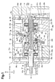
Fig. 1 is a cross-sectional view showing a compressor of a first embodiment when the displacement is maximal; -
Fig. 2 is a schematic diagram showing a control mechanism in the compressor ofFig. 1 ; -
Fig. 3 is a cross-sectional view showing the compressor ofFig. 1 when the displacement is minimal; and -
Fig. 4 is a schematic diagram showing a control mechanism in a compressor of a second embodiment. - First and second embodiments will now be described with reference to the drawings. Compressors of the first and second embodiments are each installed in a vehicle to form a refrigeration circuit of a vehicle air conditioner.
- Referring to
Figs. 1 and3 , a compressor of the first embodiment includes a housing 1, adrive shaft 3, aswash plate 5, a link mechanism 7,pistons 9, front andrear shoes actuator 13, and acontrol mechanism 15, which is shown inFig. 2 . Eachpiston 9 is provided with a pair of theshoes - As shown in
Fig. 1 , the housing 1 includes afront housing member 17, which is located at the front of the compressor, arear housing member 19, which is located at the rear of the compressor, and first andsecond cylinder blocks front housing member 17 and therear housing member 19. - The
front housing member 17 includes aboss 17a, which projects toward the front. A sealingdevice 25 is arranged in theboss 17a around thedrive shaft 3. Further, thefront housing member 17 includes afirst suction chamber 27a and afirst discharge chamber 29a. Thefirst suction chamber 27a is located in a radially inner portion of thefront housing member 17, and thefirst discharge chamber 29a is located in a radially outer portion of thefront housing member 17. - The
rear housing member 19 includes thecontrol mechanism 15. Therear housing member 19 includes asecond suction chamber 27b, asecond discharge chamber 29b, and apressure regulation chamber 31. Thesecond suction chamber 27b is located in a radially inner portion of therear housing member 19, and thesecond discharge chamber 29b is located in a radially outer portion of therear housing member 19. Thepressure regulation chamber 31 is located in a radially central portion of therear housing member 19. A discharge passage (not shown) connects thefirst discharge chamber 29a and thesecond discharge chamber 29b. The discharge passage includes a discharge port, which is in communication with the outer side of the compressor. - A
swash plate chamber 33 is defined in thefirst cylinder block 21 and thesecond cylinder block 23. Theswash plate chamber 33 is located in a central portion of the housing 1. - The
first cylinder block 21 includes first cylinder bores 21 a, which are arranged at equal angular intervals in the circumferential direction and which extend parallel to one another. Each first cylinder bore 21 a corresponds to a first cylinder bore of the present invention. - Further, the
first cylinder block 21 includes a first shaft bore 21 b. Thedrive shaft 3 extends through the first shaft bore 21 b. Thefirst cylinder block 21 also includes afirst recess 21 c, which is located at the rear side of the first shaft bore 21 b. Thefirst recess 21c is in communication with the first shaft bore 21 b and coaxial with the first shaft bore 21 b. Further, thefirst recess 21c is in communication with theswash plate chamber 33 and includes a stepped wall surface. Afirst thrust bearing 35a is arranged in a front portion of thefirst recess 21c. Thefirst cylinder block 21 includes afirst suction passage 37a that communicates theswash plate chamber 33 with thefirst suction chamber 27a. - In the same manner as the
first cylinder block 21, thesecond cylinder block 23 includes second cylinder bores 23a. Eachsecond cylinder bore 23a corresponds to a second cylinder bore of the present invention. Corresponding ones of the first cylinder bores 21 a and the second cylinder bores 23a are coaxially aligned to form cylinder bore pairs. - Further, the
second cylinder block 23 includes asecond shaft bore 23b. Thedrive shaft 3 extends through thesecond shaft bore 23b. Thesecond shaft bore 23b is in communication with thepressure regulation chamber 31. Thesecond cylinder block 23 also includes asecond recess 23c, which is located at the front side of thesecond shaft bore 23b. Thesecond recess 23c is in communication with the second shaft bore 23b and coaxial with thesecond shaft bore 23b. Further, thesecond recess 23c is in communication with theswash plate chamber 33 and includes a stepped wall surface. A second thrust bearing 35b is arranged in a rear portion of thesecond recess 23c. Thesecond cylinder block 23 includes asecond suction passage 37b that communicates theswash plate chamber 33 with thesecond suction chamber 27b. - The
swash plate chamber 33 is connected to an evaporator (not shown) via asuction port 330 formed in thesecond cylinder block 23. - A
first valve plate 39 is arranged between thefront housing member 17 and thefirst cylinder block 21. Thefirst valve plate 39 includes asuction port 39b and adischarge port 39a for each first cylinder bore 21 a. A suction valve mechanism (not shown) is provided for eachsuction port 39b. Eachsuction port 39b communicates the corresponding first cylinder bore 21 a with thefirst suction chamber 27a. A discharge valve mechanism (not shown) is provided for eachdischarge port 39a. Eachdischarge port 39a communicates the corresponding first cylinder bore 21 a with thefirst discharge chamber 29a. Thefirst valve plate 39 also includes acommunication hole 39c. Thecommunication hole 39c communicates thefirst suction chamber 27a with theswash plate chamber 33 through thefirst suction passage 37a. - A
second valve plate 41 is arranged between therear housing member 19 and thesecond cylinder block 23. In the same manner as thefirst valve plate 39, thesecond valve plate 41 includes asuction port 41 b and adischarge port 41 a for eachsecond cylinder bore 23a. A suction valve mechanism (not shown) is provided for eachsuction port 41 b. Eachsuction port 41 b communicates the correspondingsecond cylinder bore 23a with thesecond suction chamber 27b. A discharge valve mechanism (not shown) is provided for eachdischarge port 41 a. Eachdischarge port 41 a communicates the correspondingsecond cylinder bore 23a with thesecond discharge chamber 29b. Thesecond valve plate 41 also includes acommunication hole 41c. Thecommunication hole 41c communicates thesecond suction chamber 27b with theswash plate chamber 33 through thesecond suction passage 37b. - The first and
second suction chambers swash plate chamber 33 are in communication with one another through the first andsecond suction passages second suction chambers swash plate chamber 33 have substantially the same pressure. More accurately, the pressure of theswash plate chamber 33 is slightly higher than the pressure of the first andsecond suction chambers swash plate chamber 33 through thesuction port 330. Thus, the pressure of each of theswash plate chamber 33 and the first andsecond suction chambers second discharge chambers swash plate chamber 33 and the first andsecond suction chambers - The
swash plate 5, theactuator 13, and aflange 3a are arranged on thedrive shaft 3. Thedrive shaft 3 is inserted through theboss 17a toward the rear and inserted through the first and second shaft bores 21 b and 23b in the first andsecond cylinder blocks drive shaft 3 is located in theboss 17a, and the rear end is located in thepressure regulation chamber 31. The first and second shaft bores 21 b and 23b support thedrive shaft 3 in the housing 1 so that thedrive shaft 3 is rotatable about the rotation axis O. Theswash plate 5, theactuator 13, and theflange 3a are each located in theswash plate chamber 33. Theflange 3a is located between the first thrust bearing 35a and theactuator 13, more specifically, between the first thrust bearing 35a and amovable body 13b. Theflange 3a restricts contact of the first thrust bearing 35a and themovable body 13b. Radial bearings may be arranged between thedrive shaft 3 and the walls of the first and second shaft bores 21 b and 23b. - A
support member 43 is fitted to the rear portion of thedrive shaft 3. Thesupport member 43 includes aflange 43a, which is in contact with the second thrust bearing 35b, and acoupling portion 43b, which receives asecond pin 47b. Thedrive shaft 3 includes anaxial passage 3b and aradial passage 3c. Theaxial passage 3b extends through the drive shaft along the rotation axis O toward the front from the rear end of thedrive shaft 3. Theradial passage 3c extends from the front end of theaxial passage 3b in the radial direction and opens in the outer surface of thedrive shaft 3. Theaxial passage 3b and theradial passage 3c define a communication passage. The rear end of theaxial passage 3b is connected to thepressure regulation chamber 31, or the low pressure chamber. Theradial passage 3c is connected to acontrol pressure chamber 13c. Further, thedrive shaft 3 includes a step 3e. - The
swash plate 5 is an annular plate and includes afront surface 5a and arear surface 5b. Thefront surface 5a of theswash plate 5 faces the front side of the compressor in theswash plate chamber 33. Therear surface 5b of theswash plate 5 faces the rear side of the compressor in theswash plate chamber 33. Thefront surface 5a and therear surface 5b of theswash plate 5 respectively correspond to a first surface and a second surface of the present invention. In the compressor, the first cylinder bores 21 a are each located at the same side as thefront surface 5a of theswash plate 5, that is, the front side (first side). The second cylinder bores 23a are each located at the same side as therear surface 5b of theswash plate 5, that is, the rear side (second side). - The
swash plate 5 is fixed to aring plate 45. Thering plate 45 is an annular plate. Aninsertion hole 45a extends through the center of thering plate 45. Thedrive shaft 3 is inserted through theinsertion hole 45a to couple theswash plate 5 to thedrive shaft 3. This arranges theswash plate 5 in theswash plate chamber 33 at the same side as the second cylinder bores 23a, that is, at a position located toward the rear in theswash plate chamber 33. - The link mechanism 7 includes a
lug arm 49. Thelug arm 49 is arranged at the rear side of theswash plate 5 in theswash plate chamber 33 and located between theswash plate 5 and thesupport member 43. Thelug arm 49 is generally L-shaped. Thelug arm 49 contacts theflange 43a of thesupport member 43 when theswash plate 5 is inclined relative to a direction orthogonal to the rotation shaft O at the minimum angle. In the compressor, thelug arm 49 allows theswash plate 5 to be maintained at the minimum inclination angle. The distal end of thelug arm 49 includes aweight 49a. Theweight 49a extends over one half of the circumference of theactuator 13. Theweight 49a may be designed to have a suitable shape. - A
first pin 47a couples the distal end of thelug arm 49 to a top region of thering plate 45. Thus, the distal end of thelug arm 49 is supported by thering plate 45, or theswash plate 5, so that thelug arm 49 is pivotal about the axis of thefirst pin 47a, namely, a first pivot axis M1. The first pivot axis M1 extends in a direction perpendicular to the rotation axis O of thedrive shaft 3. - A
second pin 47b couples a basal end of thelug arm 49 to thesupport member 43. Thus, the basal end of thelug arm 49 is supported by thesupport member 43, or thedrive shaft 3, so that thelug arm 49 is pivotal about the axis of thesecond pin 47b, namely, a second pivot axis M2. The second pivot axis M2 extends parallel to the first pivot axis M1. Thelug arm 49 and the first andsecond pins - In the compressor, the link mechanism 7 couples the
swash plate 5 and thedrive shaft 3 so that theswash plate 5 rotates together with thedrive shaft 3. As described above, thelug arm 49 is located between theswash plate 5 and thesupport member 43. Thus, the link mechanism 7 is located in theswash plate chamber 33 at the rear side of theswash plate 5, that is, the same side as the second cylinder bores 23a as viewed from theswash plate 5. The two ends of thelug arm 49 are respectively pivotal about the first pivot axis M1 and the second pivot axis M2 so that inclination angle of theswash plate 5 is changed, as shown inFigs. 1 and3 . - The
weight 49a extends along the distal end of thelug arm 49, that is, the side opposite to the second pivot axis M2 as viewed from the first pivot axis M1. Thelug arm 49 is supported by thefirst pin 47a on thering plate 45 so that theweight 49a is inserted through agroove 45b in thering plate 45 and is located at the front side of thering plate 45, that is, the front side of theswash plate 5. Rotation of theswash plate 5 around the rotation axis O generates centrifugal force that acts on theweight 49a at the front side of theswash plate 5. - Each
piston 9 includes a front end that defines afirst piston head 9a and a rear end that defines asecond piston head 9b. Thefirst piston head 9a corresponds to a first head of the present invention, and thesecond piston head 9b corresponds to a second head of the present invention. - The
first piston head 9a is reciprocally accommodated in the corresponding first cylinder bore 21 a defining afirst compression chamber 21 d. Thesecond piston head 9b is reciprocally accommodated in the corresponding second cylinder bore 23a defining asecond compression chamber 23d. Eachpiston 9 includes arecess 9c, which accommodates thesemispherical shoes shoes swash plate 5 to the reciprocation of thepiston 9. Theshoes swash plate 5. - The
actuator 13 is located in front of theswash plate 5 in theswash plate chamber 33 and is movable into thefirst recess 21c. Theactuator 13 includes apartitioning body 13a and amovable body 13b. - The
partitioning body 13a is disk-shaped and loosely fitted to thedrive shaft 3 in theswash plate chamber 33. An O-ring 51 a is arranged on the outer circumferential surface of thepartitioning body 13a, and an O-ring 51 b is arranged on the inner circumferential surface of thepartitioning body 13a. - The
movable body 13b is tubular and has a closed end. Further, themovable body 13b includes aninsertion hole 130a, through which thedrive shaft 3 is inserted, amain body portion 130b, which extends from the front of themovable body 13b toward the rear, and acoupling portion 130c, which is formed on the rear end of themain body portion 130b. An O-ring 51c is arranged in theinsertion hole 130a. Themovable body 13b is located between the first thrust bearing 35a and theswash plate 5. - The
drive shaft 3 is inserted into themain body portion 130b of themovable body 13b and through theinsertion hole 130a. Thepartitioning body 13a is arranged in a movable manner in themain body portion 130b. Themovable body 13b is rotatable together with thedrive shaft 3 and movable along the rotation axis O of thedrive shaft 3 at the front side of theswash plate 5 in theswash plate chamber 33. In this manner, thedrive shaft 3 is inserted through theactuator 13, and theactuator 13 is rotatable integrally with thedrive shaft 3 about the rotation axis O. - The
movable body 13b and the link mechanism 7 are located at opposite sides of theswash plate 5 in theswash plate chamber 33. More specifically, theactuator 13, which includes themovable body 13b, is located in theswash plate chamber 33 at the front side of theswash plate 5, that is, the same side as the first cylinder bores 21 a as viewed from theswash plate 5. - A
third pin 47c couples a bottom region of thering plate 45 to thecoupling portion 130c of themovable body 13b. Thus, thering plate 45, or theswash plate 5, is supported by themovable body 13b so as to be pivotal about the axis of thethird pin 47c, namely, an action axis M3. The action axis M3 extends parallel to the first and second pivot axes M1 and M2. In this manner, themovable body 13b is coupled to theswash plate 5. Themovable body 13b contacts theflange 3a when theswash plate 5 is inclined at the maximum angle. In the compressor, themovable body 13b allows theswash plate 5 to be maintained at the maximum inclination angle. - The
control pressure chamber 13c is defined between thepartitioning body 13a and themovable body 13b. Theradial passage 3c extends into thecontrol pressure chamber 13c. Thecontrol pressure chamber 13c is in communication with thepressure regulation chamber 31 through theradial passage 3c and theaxial passage 3b. - As shown in
Fig. 2 , thecontrol mechanism 15 includes ableed passage 15a, agas supplying passage 15b, acontrol valve 15c, and anorifice 15d. Thebleed passage 15a and thegas supplying passage 15b form a control passage. - The
bleed passage 15a is connected to thepressure regulation chamber 31 and thesecond suction chamber 27b. Thepressure regulation chamber 31 is in communication with thecontrol pressure chamber 13c through theaxial passage 3b and theradial passage 3c. Thus, thecontrol pressure chamber 13c and thesecond suction chamber 27b are in communication with each other through thebleed passage 15a. Thebleed passage 15a includes theorifice 15d. - The
gas supplying passage 15b is connected to thepressure regulation chamber 31 and thesecond discharge chamber 29b. Thus, in the same manner as thebleed passage 15a, thecontrol pressure chamber 13c and thesecond discharge chamber 29b are in communication with each other through theaxial passage 3b and theradial passage 3c. In this manner, theaxial passage 3b and theradial passage 3c form portions of thebleed passage 15a and thegas supplying passage 15b, which serve as the control passage. - The
control valve 15c is arranged in thegas supplying passage 15b. Thecontrol valve 15c adjusts the open degree of thegas supplying passage 15b based on the pressure of thesecond suction chamber 27b. A known valve may be used as thecontrol valve 15c. - The distal end of the
drive shaft 3 includes a threadedportion 3d. The threadedportion 3d couples thedrive shaft 3 to a pulley or an electromagnetic clutch (neither shown). A belt (not shown), which is driven by a vehicle engine, runs along the pulley or a pulley of the electromagnetic clutch. - A pipe leading to the evaporator is connected to the
suction port 330. A pipe leading to a condenser is connected to a discharge port (none shown). The compressor, the evaporator, an expansion valve, the condenser, and the like form the refrigeration circuit of the vehicle air conditioner. - In the compressor, the rotation of the
drive shaft 3 rotates theswash plate 5 and reciprocates eachpiston 9 in the corresponding first and second cylinder bores 21 a and 23a. Thus, the volumes of the first andsecond compression chambers swash plate chamber 33 through thesuction port 330 from the evaporator. The refrigerant gas flows through the first andsecond suction chambers second compression chambers second discharge chambers second discharge chambers - During operation of the compressor, centrifugal force, which acts to decrease the inclination angle of the swash plate, and compression reaction, which acts to decrease the inclination angle of the
swash plate 5 through thepistons 9, are applied to the rotation members, which include theswash plate 5, thering plate 45, thelug arm 49, and thefirst pin 47a. The compressor displacement may be controlled by changing the inclination angle of theswash plate 5 thereby lengthening or shortening the stroke of thepistons 9. - More specifically, in the
control mechanism 15, when thecontrol valve 15c shown inFig. 2 decreases the open degree of thegas supplying passage 15b, the pressure of thecontrol pressure chamber 13c becomes substantially equal to the pressure of thesecond suction chamber 27b. Thus, the centrifugal force and the compression reaction acting on the rotation members move themovable body 13b toward the rear. This contracts thecontrol pressure chamber 13c and decreases the inclination angle of theswash plate 5. - As a result, referring to
Fig. 3 , theswash plate 5 pivots about the action axis M3 of theswash plate 5 and the two ends of thelug arm 49 respectively pivot about the first and second pivot axes M1 and M2 so that thelug arm 49 moves toward theflange 43a of thesupport member 43. This shortens the stroke of thepistons 9 and decreases the compressor displacement for each rotation of thedrive shaft 3. The inclination angle of theswash plate 5 inFig. 3 is the minimum inclination angle of the compressor. - In the compressor, the centrifugal force acting on the
weight 49a is applied to theswash plate 5. Thus, in the compressor, theswash plate 5 easily moves in the direction that decreases the inclination angle of theswash plate 5. Further, when themovable body 13b moves toward the rear along the rotation axis O of thedrive shaft 3, the rear end of themovable body 13b is arranged at the inner side of theweight 49a. As a result, in the compressor, when the inclination angle of theswash plate 5 decreases, theweight 49a covers about one half of the rear end of themovable body 13b. - When the
control valve 15c shown inFig. 2 increases the open degree of thegas supplying passage 15b, the pressure of thecontrol pressure chamber 13c becomes substantially equal to the pressure of thesecond discharge chamber 29b. Thus, themovable body 13b of theactuator 13 moves toward the front against the centrifugal force and the compression reaction acting on the rotation members. This enlarges thecontrol pressure chamber 13c and increases the inclination angle of theswash plate 5. - As a result, referring to
Fig. 1 , theswash plate 5 pivots in the opposite direction about the action axis M3 of theswash plate 5 and the two ends of thelug arm 49 respectively pivot in the opposite direction about the first and second pivot axes M1 and M2 so that thelug arm 49 moves away from theflange 43a of thesupport member 43. This lengthens the stroke of thepistons 9 and increases the compressor displacement for each rotation of thedrive shaft 3. The inclination angle of theswash plate 5 inFig. 1 is the maximum inclination angle of the compressor. - In the compressor, the link mechanism 7 couples the
swash plate 5 and thedrive shaft 3 so that theswash plate 5 is located near the second cylinder bores 23a in theswash plate chamber 33. Thus, in the compressor, when the inclination angle of theswash plate 5 is maximal and the stroke of thepistons 9 is maximal, the top dead center of eachfirst piston head 9a is located closest to thefirst valve plate 39, and the top dead center of eachsecond piston head 9b is located closest to thesecond valve plate 41. As the inclination angle of theswash plate 5 decreases and shortens the stroke of thepistons 9, the top dead center of eachfirst piston head 9a is gradually separated from thefirst valve plate 39. However, the top dead center of eachsecond piston head 9b remains at substantially the same position as when the stroke of thepistons 9 is maximal and is kept close to thesecond valve plate 41. - In this manner, in the compressor, when the inclination angle of the
swash plate 5 is changed, the top dead center of thesecond piston head 9b of eachpiston 9 remains at substantially the same position but the top dead center of thefirst piston head 9a of eachpiston 9 is shifted over a relatively long distance to another position. In the compressor, a relatively large open space is provided in theswash plate chamber 33 near the first cylinder bores 21 a. Further, theactuator 13 is located near the first cylinder bores 21 a in theswash plate chamber 33. Accordingly, the compressor allows theactuator 13 to be enlarged in the radial direction without the need to enlarge the housing 1 in the radial direction. This allows thecontrol pressure chamber 13c to be large. Thus, in the compressor, themovable body 13b is moved in a preferred manner by a change in the pressure of thecontrol pressure chamber 13c. - In the compressor, the
partitioning body 13a is loosely fitted to thedrive shaft 3, and themovable body 13b easily moves relative to thepartitioning body 13a. Thus, in the compressor, themovable body 13b is moved in a preferred manner along the rotation axis O. - In the compressor, the link mechanism 7 is located at the same side as the second cylinder bores 23a as viewed from the
swash plate 5. In other words, the link mechanism 7 and themovable body 13b are located at opposite sides of theswash plate 5. As described above, when the inclination angle of theswash plate 5 is changed, the top dead center of thesecond piston head 9b of eachpiston 9 remains at substantially the same position. Thus, the open space that is provided in theswash plate chamber 33 is relatively narrow near the second cylinder bores 23a. However, the link mechanism 7 of the compressor is only used to change the inclination angle of theswash plate 5. Further, thelug arm 49 is L-shaped so that thelug arm 49 is reduced in size while obtaining a sufficient pivoting range. Accordingly, even if the link mechanism 7 is arranged in theswash plate chamber 33 near the second cylinder bores 23a where open space is limited, the link mechanism 7 sufficiently functions. - Further, in the compressor, the link mechanism 7 is located at the same side as the second cylinder bores 23a as viewed from the
swash plate 5. This increases the open space near the first cylinder bores 21 a in theswash plate chamber 33. - Accordingly, the compressor of the first embodiment is compact, easy to install in a vehicle, and allows for superior displacement control.
- In the
control mechanism 15 of the compressor, thecontrol pressure chamber 13c and thesecond suction chamber 27b are in communication through thebleed passage 15a, and thecontrol pressure chamber 13c and thesecond discharge chamber 29b are in communication through thegas supplying passage 15b. Further, thecontrol valve 15c allows for adjustment of the open degree of thegas supplying passage 15b. Accordingly, in the compressor, the high pressure of thesecond discharge chamber 29b readily increases the pressure of thecontrol pressure chamber 13c to a high value so that the compressor displacement is readily increased. - Further, in the compressor, the
swash plate chamber 33 is used as a refrigerant gas passage leading to the first andsecond suction chambers - A compressor of the second embodiment includes a
control mechanism 16 shown inFig. 4 in lieu of thecontrol mechanism 15 used in the compressor of the first embodiment. Thecontrol mechanism 16 includes ableed passage 16a, agas supplying passage 16b, acontrol valve 16c, and anorifice 16d. Thebleed passage 16a and thegas supplying passage 16b form a control passage. - The
bleed passage 16a is connected to thepressure regulation chamber 31 and thesecond suction chamber 27b. Thus, thecontrol pressure chamber 13c and thesecond suction chamber 27b are in communication with each other through thebleed passage 16a. Thegas supplying passage 16b is connected to thepressure regulation chamber 31 and thesecond discharge chamber 29b. Thus, thecontrol pressure chamber 13c and thepressure regulation chamber 31 are in communication with thesecond discharge chamber 29b through thegas supplying passage 16b. Thegas supplying passage 16b includes theorifice 16d. - The
control valve 16c is arranged in thebleed passage 16a. Thecontrol valve 16c adjusts the open degree of thebleed passage 16a based on the pressure of thesecond suction chamber 27b. In the same manner as thecontrol valve 15c, a known valve may be used as thecontrol valve 16c. Further, theaxial passage 3b and theradial passage 3c form portions of thebleed passage 16a and thegas supplying passage 16b. Other portions of the compressor have the same structure as the compressor of the first embodiment. Same reference numerals are given to those components that are the same as the corresponding components of the first embodiment. Such components will not be described in detail. - In the
control mechanism 16 of the compressor, when thecontrol valve 16c decreases the open degree of thebleed passage 16a, the pressure of thecontrol pressure chamber 13c becomes substantially equal to the pressure of thesecond discharge chamber 29b. Thus, the centrifugal force and the compression reaction acting on the rotation members move themovable body 13b of theactuator 13 toward the front. This expands thecontrol pressure chamber 13c and increases the inclination angle of theswash plate 5. - As a result, in the same manner as the compressor of the first embodiment, the inclination angle of the
swash plate 5 increases in the compressor and lengthens the stroke of thepistons 9. This increases the compressor displacement for each rotation of the drive shaft 3 (refer toFig. 1 ). - When the
control valve 16c increases the open degree of thebleed passage 16a, the pressure of thecontrol pressure chamber 13c becomes substantially equal to the pressure of thesecond suction chamber 27b. Thus, the centrifugal force and the compression reaction acting on the rotation members move themovable body 13b toward the rear. This contracts thecontrol pressure chamber 13c and decreases the inclination angle of theswash plate 5. - As a result, the inclination angle of the
swash plate 5 decreases in the compressor and shortens the stroke of thepistons 9. This decreases the compressor displacement for each rotation of the drive shaft 3 (refer toFig. 3 ). - In the
control mechanism 16 of the compressor, thecontrol valve 16c allows for adjustment of the open degree of thebleed passage 16a. Thus, in the compressor, the low pressure of thesecond suction chamber 27b gradually decreases the pressure of thecontrol pressure chamber 13c to a low value so that a suitable driving feel of the vehicle is maintained. Otherwise, the operation of the compressor is the same as the compressor of the first embodiment. - The present invention is not restricted to the first and second embodiments described above. It should be apparent to those skilled in the art that the present invention may be embodied in many other specific forms without departing from the spirit or scope of the invention. Particularly, it should be understood that the present invention may be embodied in the following forms.
- In the compressors of the first and second embodiments, refrigerant gas is drawn into the first and
second suction chambers swash plate chamber 33. Instead, refrigerant gas may be directly drawn into the first andsecond suction chambers second suction chambers swash plate chamber 33 in the compressor, and theswash plate chamber 33 is configured to serve as a low pressure chamber. - The
pressure regulation chamber 31 may be omitted from the compressors of the first and second embodiments. - The present examples and embodiments are to be considered as illustrative and not restrictive, and the invention is not to be limited to the details given herein, but may be modified within the scope and equivalence of the appended claims.
- An actuator of a compressor includes a partitioning body, which is rotatable integrally with a drive shaft and loosely fitted to the drive shaft in the swash plate chamber, a movable body, which is coupled to a swash plate and movable relative to the partitioning body along the axis of the drive shaft, and a control pressure chamber, the pressure of which moves the movable body. A control mechanism changes the pressure of the control pressure chamber to move the movable body. A link mechanism shifts a top dead center of a first head of a piston over a longer distance than a top dead center of a second head of the piston when the inclination angle of the swash plate changes. The actuator is located at the same side as the first cylinder bore, which accommodates the first head, as viewed from the swash plate.
Claims (2)
- A variable displacement swash plate compressor comprising:a housing (1) including a suction chamber (27a, 27b), a discharge chamber (29a, 29b), a swash plate chamber (33), and a cylinder bore pair (21 a, 23a);a drive shaft (3) rotationally supported by the housing (1);a swash plate (5) that is rotatable together with the drive shaft (3) in the swash plate chamber (33);a link mechanism (7) arranged between the drive shaft (3) and the swash plate (5), wherein the link mechanism (7) allows for changes in an inclination angle of the swash plate (5) relative to a direction orthogonal to a rotation axis of the drive shaft (3);a piston (9) reciprocally accommodated in the cylinder bore pair (21 a, 23a);a conversion mechanism (11 a, 11 b) that is configured to reciprocate the piston (9) in the cylinder bore pair (21 a, 23a) with a stroke that is in accordance with the inclination angle of the swash plate (5) when the swash plate (5) rotates;an actuator (13) capable of changing the inclination angle of the swash plate (5); anda control mechanism (15, 16) that is configured to control the actuator (13);wherein the cylinder bore pair (21 a, 23a) includes a first cylinder bore (21 a), which is located at a first side of the swash plate (5), and a second cylinder bore (23a), which is located at a second side of the swash plate (5);the piston (9) includes a first head (9a), which reciprocates in the first cylinder bore (21 a), and a second head (9b), which is formed integrally with the first head (9a) and reciprocates in the second cylinder bore (23a);the link mechanism (7) is configured to shift a top dead center of the first head (9a) over a longer distance than a top dead center of the second head (9b) when the inclination angle of the swash plate (5) changes;the actuator (13) is located at the same side as the first cylinder bore (21 a) as viewed from the swash plate (5), and the actuator (13) is rotatable integrally with the drive shaft (3);the actuator (13) includes a partitioning body (13a), which is loosely fitted to the drive shaft (3) in the swash plate chamber (33), a movable body (13b), which is coupled to the swash plate (5) and movable relative to the partitioning body (13a) along the rotation axis, and a control pressure chamber (13c), which is defined by the partitioning body (13a) and the movable body (13b), wherein pressure of the control pressure chamber (13c) moves the movable body (13b); andthe control mechanism (15, 16) is configured to change the pressure of the control pressure chamber (13c) to move the movable body (13b).
- The variable displacement swash plate compressor according to claim 1, wherein the link mechanism (7) is located at the same side as the second cylinder bore (23a) as viewed from the swash plate (5).
Applications Claiming Priority (1)
| Application Number | Priority Date | Filing Date | Title |
|---|---|---|---|
| JP2014070168A JP6194836B2 (en) | 2014-03-28 | 2014-03-28 | Variable capacity swash plate compressor |
Publications (2)
| Publication Number | Publication Date |
|---|---|
| EP2927496A2 true EP2927496A2 (en) | 2015-10-07 |
| EP2927496A3 EP2927496A3 (en) | 2015-12-16 |
Family
ID=52736913
Family Applications (1)
| Application Number | Title | Priority Date | Filing Date |
|---|---|---|---|
| EP15160833.8A Withdrawn EP2927496A3 (en) | 2014-03-28 | 2015-03-25 | Variable displacement swash plate compressor |
Country Status (5)
| Country | Link |
|---|---|
| US (1) | US9903354B2 (en) |
| EP (1) | EP2927496A3 (en) |
| JP (1) | JP6194836B2 (en) |
| KR (1) | KR101729830B1 (en) |
| CN (1) | CN104948417B (en) |
Families Citing this family (1)
| Publication number | Priority date | Publication date | Assignee | Title |
|---|---|---|---|---|
| DE102019107949A1 (en) * | 2018-03-30 | 2019-10-02 | Kabushiki Kaisha Toyota Jidoshokki | piston compressor |
Citations (2)
| Publication number | Priority date | Publication date | Assignee | Title |
|---|---|---|---|---|
| JPH0219665A (en) | 1988-07-05 | 1990-01-23 | Toyota Autom Loom Works Ltd | Variable displacement swash plate type compressor |
| JPH05172052A (en) | 1991-12-18 | 1993-07-09 | Sanden Corp | Variable displacement swash plate type compressor |
Family Cites Families (52)
| Publication number | Priority date | Publication date | Assignee | Title |
|---|---|---|---|---|
| US4037993A (en) | 1976-04-23 | 1977-07-26 | Borg-Warner Corporation | Control system for variable displacement compressor |
| US4061443A (en) | 1976-12-02 | 1977-12-06 | General Motors Corporation | Variable stroke compressor |
| US4174191A (en) | 1978-01-18 | 1979-11-13 | Borg-Warner Corporation | Variable capacity compressor |
| JPS58162781A (en) * | 1982-03-20 | 1983-09-27 | Toyoda Autom Loom Works Ltd | Apparatus for controlling inclination angle of swash plate of swash plate type variable displacement compressor |
| US4606705A (en) | 1985-08-02 | 1986-08-19 | General Motors Corporation | Variable displacement compressor control valve arrangement |
| JPS62225782A (en) | 1986-03-27 | 1987-10-03 | Nippon Denso Co Ltd | Variable displacement oscillating plate type compressor |
| JPS62247184A (en) | 1986-04-18 | 1987-10-28 | Nippon Radiator Co Ltd | Variable displacement swash plate type compressor |
| JPS6477771A (en) | 1987-09-18 | 1989-03-23 | Hitachi Ltd | Variable delivery compressor |
| US4963074A (en) | 1988-01-08 | 1990-10-16 | Nippondenso Co., Ltd. | Variable displacement swash-plate type compressor |
| JP2503569B2 (en) | 1988-02-24 | 1996-06-05 | 株式会社豊田自動織機製作所 | Wobble type compressor drive controller |
| JP2569737B2 (en) * | 1988-07-04 | 1997-01-08 | 株式会社豊田自動織機製作所 | Variable displacement swash plate compressor |
| JP2713759B2 (en) * | 1989-04-05 | 1998-02-16 | 株式会社豊田自動織機製作所 | Variable displacement swash plate compressor |
| JPH07111171B2 (en) * | 1989-11-02 | 1995-11-29 | 株式会社豊田自動織機製作所 | Continuously variable capacity swash plate compressor |
| JPH048875A (en) * | 1990-04-25 | 1992-01-13 | Nippondenso Co Ltd | Swash plate variable displacement compressor |
| JP2846096B2 (en) * | 1990-10-10 | 1999-01-13 | 株式会社日本自動車部品総合研究所 | Variable displacement swash plate type compressor |
| JP2532406Y2 (en) | 1991-05-09 | 1997-04-16 | 株式会社豊田自動織機製作所 | Gasket with retainer for compressor |
| JPH05312144A (en) | 1992-05-08 | 1993-11-22 | Sanden Corp | Variable displacement swash plate type compressor |
| JPH0821358A (en) * | 1994-07-04 | 1996-01-23 | Sanden Corp | Variable displacement type compressor with swash plate |
| JP2932952B2 (en) | 1994-12-07 | 1999-08-09 | 株式会社豊田自動織機製作所 | Clutchless variable displacement compressor |
| KR100203975B1 (en) | 1995-10-26 | 1999-06-15 | 이소가이 치세이 | Cam Plate Variable Capacity Compressor |
| JPH102284A (en) | 1996-06-17 | 1998-01-06 | Toyota Autom Loom Works Ltd | Variable displacement compressor and its control method |
| JPH1054349A (en) | 1996-08-12 | 1998-02-24 | Toyota Autom Loom Works Ltd | Variable displacement compressor |
| JPH10153171A (en) * | 1996-11-22 | 1998-06-09 | Toyota Autom Loom Works Ltd | Both heads piston type variable capacity compressor |
| US6077047A (en) * | 1997-01-24 | 2000-06-20 | Kabushiki Kaisha Toyoda Jidoshokki Seisakusho | Variable displacement compressor |
| JPH10246181A (en) | 1997-02-28 | 1998-09-14 | Toyota Autom Loom Works Ltd | Variable displacement compressor |
| JP3582284B2 (en) | 1997-03-13 | 2004-10-27 | 株式会社豊田自動織機 | Refrigeration circuit and compressor |
| JP4007637B2 (en) | 1997-03-31 | 2007-11-14 | サンデン株式会社 | Variable capacity compressor |
| JPH11257217A (en) | 1998-03-16 | 1999-09-21 | Toyota Autom Loom Works Ltd | One side variable displacement compressor |
| JP2000186668A (en) | 1998-12-22 | 2000-07-04 | Toyota Autom Loom Works Ltd | Capacity control structure for variable displacement compressor |
| DE19939131A1 (en) | 1999-08-18 | 2001-03-08 | Zexel Gmbh | Axial piston engine with an infinitely adjustable piston stroke |
| JP2001063353A (en) | 1999-08-24 | 2001-03-13 | Toyota Autom Loom Works Ltd | Controller for variable displacement compressor |
| JP2001107849A (en) | 1999-10-08 | 2001-04-17 | Toyota Autom Loom Works Ltd | Variable displacement compressor |
| JP3933369B2 (en) | 2000-04-04 | 2007-06-20 | サンデン株式会社 | Piston type variable capacity compressor |
| JP2002031050A (en) | 2000-07-17 | 2002-01-31 | Toyota Industries Corp | Compressor |
| WO2002061280A1 (en) | 2001-01-29 | 2002-08-08 | Zexel Valeo Climate Control Corporation | Variable displacement type swash plate clutch-less compressor |
| JP4023351B2 (en) | 2002-05-29 | 2007-12-19 | 株式会社デンソー | Swing swash plate type variable capacity compressor |
| JP2004060644A (en) | 2002-06-05 | 2004-02-26 | Denso Corp | Compressor device and control method thereof |
| JP4378190B2 (en) | 2004-02-25 | 2009-12-02 | 株式会社ミクニ | Plunger type fluid discharge device |
| JP2006022785A (en) | 2004-07-09 | 2006-01-26 | Toyota Industries Corp | Variable displacement compressor |
| JP4330576B2 (en) | 2005-10-28 | 2009-09-16 | サンデン株式会社 | Compressor |
| JP2008045523A (en) | 2006-08-21 | 2008-02-28 | Toyota Industries Corp | Capacity control structure in variable displacement compressor |
| US20090107327A1 (en) | 2007-10-03 | 2009-04-30 | Masaki Ota | Capacity-variable type swash plate compressor |
| JP6003547B2 (en) | 2012-11-05 | 2016-10-05 | 株式会社豊田自動織機 | Variable capacity swash plate compressor |
| JP5870902B2 (en) | 2012-11-05 | 2016-03-01 | 株式会社豊田自動織機 | Variable capacity swash plate compressor |
| JP6028525B2 (en) | 2012-11-05 | 2016-11-16 | 株式会社豊田自動織機 | Variable capacity swash plate compressor |
| WO2014069618A1 (en) | 2012-11-05 | 2014-05-08 | 株式会社 豊田自動織機 | Variable displacement swash-plate compressor |
| JP6003546B2 (en) | 2012-11-05 | 2016-10-05 | 株式会社豊田自動織機 | Variable capacity swash plate compressor |
| JP6028524B2 (en) | 2012-11-05 | 2016-11-16 | 株式会社豊田自動織機 | Variable capacity swash plate compressor |
| JP6083291B2 (en) | 2013-03-27 | 2017-02-22 | 株式会社豊田自動織機 | Variable capacity swash plate compressor |
| JP6032098B2 (en) | 2013-03-29 | 2016-11-24 | 株式会社豊田自動織機 | Variable capacity swash plate compressor |
| JP6115258B2 (en) | 2013-03-29 | 2017-04-19 | 株式会社豊田自動織機 | Double-head piston type swash plate compressor |
| JP2015183615A (en) | 2014-03-25 | 2015-10-22 | 株式会社豊田自動織機 | Variable displacement swash plate compressor |
-
2014
- 2014-03-28 JP JP2014070168A patent/JP6194836B2/en not_active Expired - Fee Related
-
2015
- 2015-03-24 US US14/666,860 patent/US9903354B2/en not_active Expired - Fee Related
- 2015-03-24 KR KR1020150040735A patent/KR101729830B1/en not_active Expired - Fee Related
- 2015-03-25 EP EP15160833.8A patent/EP2927496A3/en not_active Withdrawn
- 2015-03-25 CN CN201510134127.7A patent/CN104948417B/en not_active Expired - Fee Related
Patent Citations (2)
| Publication number | Priority date | Publication date | Assignee | Title |
|---|---|---|---|---|
| JPH0219665A (en) | 1988-07-05 | 1990-01-23 | Toyota Autom Loom Works Ltd | Variable displacement swash plate type compressor |
| JPH05172052A (en) | 1991-12-18 | 1993-07-09 | Sanden Corp | Variable displacement swash plate type compressor |
Also Published As
| Publication number | Publication date |
|---|---|
| KR101729830B1 (en) | 2017-04-24 |
| EP2927496A3 (en) | 2015-12-16 |
| US9903354B2 (en) | 2018-02-27 |
| US20150275880A1 (en) | 2015-10-01 |
| JP6194836B2 (en) | 2017-09-13 |
| KR20150112835A (en) | 2015-10-07 |
| CN104948417B (en) | 2017-04-12 |
| JP2015190431A (en) | 2015-11-02 |
| CN104948417A (en) | 2015-09-30 |
Similar Documents
| Publication | Publication Date | Title |
|---|---|---|
| EP2728182A2 (en) | Swash plate type variable displacement compressor | |
| EP2728185B1 (en) | Swash plate type variable displacement compressor | |
| EP2728183A2 (en) | Swash plate type variable displacement compressor | |
| EP2927493A2 (en) | Variable displacement swash plate compressor | |
| EP2924287B1 (en) | Variable displacement swash plate type compressor | |
| EP2784318B1 (en) | Variable displacement swash plate compressor | |
| EP2927497A2 (en) | Variable displacement swash plate compressor | |
| EP2927496A2 (en) | Variable displacement swash plate compressor | |
| JP6201852B2 (en) | Variable capacity swash plate compressor | |
| KR101729831B1 (en) | Variable displacement swash plate compressor | |
| EP2944814A2 (en) | Variable displacement swash plate compressor | |
| US9903353B2 (en) | Variable displacement swash plate compressor | |
| JP6032228B2 (en) | Variable capacity swash plate compressor | |
| WO2014157209A1 (en) | Volume variable swash plate-type compressor |
Legal Events
| Date | Code | Title | Description |
|---|---|---|---|
| PUAI | Public reference made under article 153(3) epc to a published international application that has entered the european phase |
Free format text: ORIGINAL CODE: 0009012 |
|
| 17P | Request for examination filed |
Effective date: 20150325 |
|
| AK | Designated contracting states |
Kind code of ref document: A2 Designated state(s): AL AT BE BG CH CY CZ DE DK EE ES FI FR GB GR HR HU IE IS IT LI LT LU LV MC MK MT NL NO PL PT RO RS SE SI SK SM TR |
|
| AX | Request for extension of the european patent |
Extension state: BA ME |
|
| PUAL | Search report despatched |
Free format text: ORIGINAL CODE: 0009013 |
|
| AK | Designated contracting states |
Kind code of ref document: A3 Designated state(s): AL AT BE BG CH CY CZ DE DK EE ES FI FR GB GR HR HU IE IS IT LI LT LU LV MC MK MT NL NO PL PT RO RS SE SI SK SM TR |
|
| AX | Request for extension of the european patent |
Extension state: BA ME |
|
| RIC1 | Information provided on ipc code assigned before grant |
Ipc: F04B 27/10 20060101AFI20151109BHEP Ipc: F04B 39/12 20060101ALI20151109BHEP Ipc: F04B 27/18 20060101ALI20151109BHEP |
|
| STAA | Information on the status of an ep patent application or granted ep patent |
Free format text: STATUS: THE APPLICATION HAS BEEN WITHDRAWN |
|
| 18W | Application withdrawn |
Effective date: 20180220 |