EP2927444A1 - Exhaust purification filter - Google Patents
Exhaust purification filter Download PDFInfo
- Publication number
- EP2927444A1 EP2927444A1 EP12889051.4A EP12889051A EP2927444A1 EP 2927444 A1 EP2927444 A1 EP 2927444A1 EP 12889051 A EP12889051 A EP 12889051A EP 2927444 A1 EP2927444 A1 EP 2927444A1
- Authority
- EP
- European Patent Office
- Prior art keywords
- coated zone
- exhaust gas
- partition
- coated
- portion located
- Prior art date
- Legal status (The legal status is an assumption and is not a legal conclusion. Google has not performed a legal analysis and makes no representation as to the accuracy of the status listed.)
- Withdrawn
Links
Images



Classifications
-
- B—PERFORMING OPERATIONS; TRANSPORTING
- B01—PHYSICAL OR CHEMICAL PROCESSES OR APPARATUS IN GENERAL
- B01D—SEPARATION
- B01D53/00—Separation of gases or vapours; Recovering vapours of volatile solvents from gases; Chemical or biological purification of waste gases, e.g. engine exhaust gases, smoke, fumes, flue gases, aerosols
- B01D53/34—Chemical or biological purification of waste gases
- B01D53/92—Chemical or biological purification of waste gases of engine exhaust gases
- B01D53/94—Chemical or biological purification of waste gases of engine exhaust gases by catalytic processes
-
- B—PERFORMING OPERATIONS; TRANSPORTING
- B01—PHYSICAL OR CHEMICAL PROCESSES OR APPARATUS IN GENERAL
- B01D—SEPARATION
- B01D46/00—Filters or filtering processes specially modified for separating dispersed particles from gases or vapours
- B01D46/24—Particle separators, e.g. dust precipitators, using rigid hollow filter bodies
- B01D46/2403—Particle separators, e.g. dust precipitators, using rigid hollow filter bodies characterised by the physical shape or structure of the filtering element
- B01D46/2418—Honeycomb filters
- B01D46/2425—Honeycomb filters characterized by parameters related to the physical properties of the honeycomb structure material
- B01D46/2429—Honeycomb filters characterized by parameters related to the physical properties of the honeycomb structure material of the honeycomb walls or cells
-
- B—PERFORMING OPERATIONS; TRANSPORTING
- B01—PHYSICAL OR CHEMICAL PROCESSES OR APPARATUS IN GENERAL
- B01D—SEPARATION
- B01D46/00—Filters or filtering processes specially modified for separating dispersed particles from gases or vapours
- B01D46/24—Particle separators, e.g. dust precipitators, using rigid hollow filter bodies
- B01D46/2403—Particle separators, e.g. dust precipitators, using rigid hollow filter bodies characterised by the physical shape or structure of the filtering element
- B01D46/2418—Honeycomb filters
- B01D46/2425—Honeycomb filters characterized by parameters related to the physical properties of the honeycomb structure material
- B01D46/24492—Pore diameter
-
- B—PERFORMING OPERATIONS; TRANSPORTING
- B01—PHYSICAL OR CHEMICAL PROCESSES OR APPARATUS IN GENERAL
- B01D—SEPARATION
- B01D46/00—Filters or filtering processes specially modified for separating dispersed particles from gases or vapours
- B01D46/24—Particle separators, e.g. dust precipitators, using rigid hollow filter bodies
- B01D46/2403—Particle separators, e.g. dust precipitators, using rigid hollow filter bodies characterised by the physical shape or structure of the filtering element
- B01D46/2418—Honeycomb filters
- B01D46/2451—Honeycomb filters characterized by the geometrical structure, shape, pattern or configuration or parameters related to the geometry of the structure
- B01D46/2474—Honeycomb filters characterized by the geometrical structure, shape, pattern or configuration or parameters related to the geometry of the structure of the walls along the length of the honeycomb
-
- B—PERFORMING OPERATIONS; TRANSPORTING
- B01—PHYSICAL OR CHEMICAL PROCESSES OR APPARATUS IN GENERAL
- B01D—SEPARATION
- B01D46/00—Filters or filtering processes specially modified for separating dispersed particles from gases or vapours
- B01D46/24—Particle separators, e.g. dust precipitators, using rigid hollow filter bodies
- B01D46/2403—Particle separators, e.g. dust precipitators, using rigid hollow filter bodies characterised by the physical shape or structure of the filtering element
- B01D46/2418—Honeycomb filters
- B01D46/2451—Honeycomb filters characterized by the geometrical structure, shape, pattern or configuration or parameters related to the geometry of the structure
- B01D46/2482—Thickness, height, width, length or diameter
-
- B—PERFORMING OPERATIONS; TRANSPORTING
- B01—PHYSICAL OR CHEMICAL PROCESSES OR APPARATUS IN GENERAL
- B01J—CHEMICAL OR PHYSICAL PROCESSES, e.g. CATALYSIS OR COLLOID CHEMISTRY; THEIR RELEVANT APPARATUS
- B01J23/00—Catalysts comprising metals or metal oxides or hydroxides, not provided for in group B01J21/00
- B01J23/38—Catalysts comprising metals or metal oxides or hydroxides, not provided for in group B01J21/00 of noble metals
- B01J23/40—Catalysts comprising metals or metal oxides or hydroxides, not provided for in group B01J21/00 of noble metals of the platinum group metals
-
- B—PERFORMING OPERATIONS; TRANSPORTING
- B01—PHYSICAL OR CHEMICAL PROCESSES OR APPARATUS IN GENERAL
- B01J—CHEMICAL OR PHYSICAL PROCESSES, e.g. CATALYSIS OR COLLOID CHEMISTRY; THEIR RELEVANT APPARATUS
- B01J35/00—Catalysts, in general, characterised by their form or physical properties
- B01J35/19—Catalysts containing parts with different compositions
-
- B—PERFORMING OPERATIONS; TRANSPORTING
- B01—PHYSICAL OR CHEMICAL PROCESSES OR APPARATUS IN GENERAL
- B01J—CHEMICAL OR PHYSICAL PROCESSES, e.g. CATALYSIS OR COLLOID CHEMISTRY; THEIR RELEVANT APPARATUS
- B01J35/00—Catalysts, in general, characterised by their form or physical properties
- B01J35/40—Catalysts, in general, characterised by their form or physical properties characterised by dimensions, e.g. grain size
-
- B—PERFORMING OPERATIONS; TRANSPORTING
- B01—PHYSICAL OR CHEMICAL PROCESSES OR APPARATUS IN GENERAL
- B01J—CHEMICAL OR PHYSICAL PROCESSES, e.g. CATALYSIS OR COLLOID CHEMISTRY; THEIR RELEVANT APPARATUS
- B01J35/00—Catalysts, in general, characterised by their form or physical properties
- B01J35/50—Catalysts, in general, characterised by their form or physical properties characterised by their shape or configuration
- B01J35/56—Foraminous structures having flow-through passages or channels, e.g. grids or three-dimensional [3D] monoliths
-
- B—PERFORMING OPERATIONS; TRANSPORTING
- B01—PHYSICAL OR CHEMICAL PROCESSES OR APPARATUS IN GENERAL
- B01J—CHEMICAL OR PHYSICAL PROCESSES, e.g. CATALYSIS OR COLLOID CHEMISTRY; THEIR RELEVANT APPARATUS
- B01J35/00—Catalysts, in general, characterised by their form or physical properties
- B01J35/60—Catalysts, in general, characterised by their form or physical properties characterised by their surface properties or porosity
-
- B—PERFORMING OPERATIONS; TRANSPORTING
- B01—PHYSICAL OR CHEMICAL PROCESSES OR APPARATUS IN GENERAL
- B01J—CHEMICAL OR PHYSICAL PROCESSES, e.g. CATALYSIS OR COLLOID CHEMISTRY; THEIR RELEVANT APPARATUS
- B01J35/00—Catalysts, in general, characterised by their form or physical properties
- B01J35/60—Catalysts, in general, characterised by their form or physical properties characterised by their surface properties or porosity
- B01J35/64—Pore diameter
- B01J35/647—2-50 nm
-
- B—PERFORMING OPERATIONS; TRANSPORTING
- B01—PHYSICAL OR CHEMICAL PROCESSES OR APPARATUS IN GENERAL
- B01J—CHEMICAL OR PHYSICAL PROCESSES, e.g. CATALYSIS OR COLLOID CHEMISTRY; THEIR RELEVANT APPARATUS
- B01J35/00—Catalysts, in general, characterised by their form or physical properties
- B01J35/60—Catalysts, in general, characterised by their form or physical properties characterised by their surface properties or porosity
- B01J35/64—Pore diameter
- B01J35/651—50-500 nm
-
- F—MECHANICAL ENGINEERING; LIGHTING; HEATING; WEAPONS; BLASTING
- F01—MACHINES OR ENGINES IN GENERAL; ENGINE PLANTS IN GENERAL; STEAM ENGINES
- F01N—GAS-FLOW SILENCERS OR EXHAUST APPARATUS FOR MACHINES OR ENGINES IN GENERAL; GAS-FLOW SILENCERS OR EXHAUST APPARATUS FOR INTERNAL-COMBUSTION ENGINES
- F01N3/00—Exhaust or silencing apparatus having means for purifying, rendering innocuous, or otherwise treating exhaust
- F01N3/02—Exhaust or silencing apparatus having means for purifying, rendering innocuous, or otherwise treating exhaust for cooling, or for removing solid constituents of, exhaust
- F01N3/021—Exhaust or silencing apparatus having means for purifying, rendering innocuous, or otherwise treating exhaust for cooling, or for removing solid constituents of, exhaust by means of filters
- F01N3/022—Exhaust or silencing apparatus having means for purifying, rendering innocuous, or otherwise treating exhaust for cooling, or for removing solid constituents of, exhaust by means of filters characterised by specially adapted filtering structure, e.g. honeycomb, mesh or fibrous
- F01N3/0222—Exhaust or silencing apparatus having means for purifying, rendering innocuous, or otherwise treating exhaust for cooling, or for removing solid constituents of, exhaust by means of filters characterised by specially adapted filtering structure, e.g. honeycomb, mesh or fibrous the structure being monolithic, e.g. honeycombs
-
- F—MECHANICAL ENGINEERING; LIGHTING; HEATING; WEAPONS; BLASTING
- F01—MACHINES OR ENGINES IN GENERAL; ENGINE PLANTS IN GENERAL; STEAM ENGINES
- F01N—GAS-FLOW SILENCERS OR EXHAUST APPARATUS FOR MACHINES OR ENGINES IN GENERAL; GAS-FLOW SILENCERS OR EXHAUST APPARATUS FOR INTERNAL-COMBUSTION ENGINES
- F01N3/00—Exhaust or silencing apparatus having means for purifying, rendering innocuous, or otherwise treating exhaust
- F01N3/02—Exhaust or silencing apparatus having means for purifying, rendering innocuous, or otherwise treating exhaust for cooling, or for removing solid constituents of, exhaust
- F01N3/021—Exhaust or silencing apparatus having means for purifying, rendering innocuous, or otherwise treating exhaust for cooling, or for removing solid constituents of, exhaust by means of filters
- F01N3/033—Exhaust or silencing apparatus having means for purifying, rendering innocuous, or otherwise treating exhaust for cooling, or for removing solid constituents of, exhaust by means of filters in combination with other devices
- F01N3/035—Exhaust or silencing apparatus having means for purifying, rendering innocuous, or otherwise treating exhaust for cooling, or for removing solid constituents of, exhaust by means of filters in combination with other devices with catalytic reactors
-
- F—MECHANICAL ENGINEERING; LIGHTING; HEATING; WEAPONS; BLASTING
- F01—MACHINES OR ENGINES IN GENERAL; ENGINE PLANTS IN GENERAL; STEAM ENGINES
- F01N—GAS-FLOW SILENCERS OR EXHAUST APPARATUS FOR MACHINES OR ENGINES IN GENERAL; GAS-FLOW SILENCERS OR EXHAUST APPARATUS FOR INTERNAL-COMBUSTION ENGINES
- F01N2510/00—Surface coverings
- F01N2510/06—Surface coverings for exhaust purification, e.g. catalytic reaction
- F01N2510/068—Surface coverings for exhaust purification, e.g. catalytic reaction characterised by the distribution of the catalytic coatings
- F01N2510/0682—Surface coverings for exhaust purification, e.g. catalytic reaction characterised by the distribution of the catalytic coatings having a discontinuous, uneven or partially overlapping coating of catalytic material, e.g. higher amount of material upstream than downstream or vice versa
Definitions
- the present invention relates to an exhaust gas purification filter.
- a compression-ignition internal combustion engine in which a particulate filter that collects particulate matter in exhaust gas is arranged within an exhaust passage has been known.
- the particulate filter includes exhaust gas inflow passages and exhaust gas outflow passages that are alternately arranged, and porous partitions that separate the exhaust gas inflow passages and the exhaust gas outflow passages from each other.
- a downstream end of each exhaust gas inflow passage is closed by a downstream-side plug and an upstream end of each exhaust gas outflow passage is closed by an upstream-side plug. Therefore, exhaust gas first flows into the exhaust gas inflow passages, then passes through the surrounding partitions, and flows out into the adjacent exhaust gas outflow passages. As a result, particulate matter in the exhaust gas is collected on the partitions and is thus suppressed from being released into the atmosphere.
- a PM removing process in which the temperature of the particulate filter is increased while the particulate filter is maintained in an oxidizing atmosphere, is performed to burn the particulate matter, thereby removing it from the particulate filter.
- a non-combustible component called "ash" is contained in exhaust gas.
- the ash is collected along with the particulate matter on the particulate filter.
- the ash is not burnt or vaporized but remains on the particulate filter.
- the pressure loss increases gradually in the particulate filter. Consequently, output of the engine may decrease even if the PM removing process is repeatedly performed.
- Patent Literature 1 a particulate filter in which a through-hole is formed in each downstream-side plug to allow the ash to flow out of the particulate filter through the through-holes has been known (see Patent Literature 1).
- the through-holes are blocked by particulate matter.
- the particulate filter can collect particulate matter in the same manner as a conventional particulate filter that does not have any through-holes.
- the particulate matter blocking the through-hole is removed and thus the through-holes are opened.
- the ash on the particulate filter is discharged from the particulate filter through the through-holes.
- PATENT LITERATURE 1 Japanese Patent Application Publication No. 2004-130229
- particulate matter flows out of the particulate filter through the through-holes during a period from the start of the operation of the engine or the end of the PM removing process until blocking of the through-holes.
- the diameter of each through-hole is set to 0.2 mm or more, a considerable amount of time is required for the through-holes having such a large diameter to be closed by particulate matter. This means that quite a large amount of the particulate matter flows out of the particulate filter through the through-holes.
- An object of the invention is to provide an exhaust gas purification filter that can suppress an increase in pressure loss of the exhaust gas purification filter caused by the ash while reliably collecting particulate matter.
- the invention provides an exhaust gas purification filter that is suitable for arrangement in an exhaust passage of an internal combustion engine and for collecting particulate matter contained in exhaust gas, the exhaust gas purification filter comprising: exhaust gas inflow passages and exhaust gas outflow passages that are arranged alternately; and porous partitions that separate the exhaust gas inflow passages and the exhaust gas outflow passages from each other, wherein each of the partitions is divided into a coated zone in which a surface of a partition base is coated with a coating layer having a smaller average pore diameter than an average pore diameter of the partition base and a non-coated zone that is located on a downstream side of the coated zone and in which a surface of the partition base is not coated with the coating layer, wherein a pore diameter of the partitions is set such that ash contained in the exhaust gas is able to pass through the partitions in the non-coated zone, and wherein a passage resistance of a partition portion located in the coated zone, the passage resistance being in a thickness direction of the partition portion located in the coated zone, is
- the number of pores in a partition base portion located in the coated zone is larger than the number of pores in a partition base portion located in the non-coated zone.
- a length of the coated zone in a longitudinal direction of the coated zone is longer than a length of the non-coated zone in a longitudinal direction of the non-coated zone.
- a pore density of the partition base portion located in the coated zone is higher than a pore density of the partition base portion located in the non-coated zone.
- an average pore diameter of a partition base portion located in the coated zone is larger than an average pore diameter of a partition base portion located in the non-coated zone.
- a thickness of a partition base portion located in the coated zone is smaller than a thickness of a partition base portion located in the non-coated zone.
- an average pore diameter of the partition base is set to 25 ⁇ m or more and 100 ⁇ m or less.
- the coating layer is formed from metallic particles having an oxidizing function.
- an average diameter of particles that form the coating layer is set to 1 ⁇ m or more and 10 ⁇ m or less.
- the exhaust gas purification filter of the invention can suppress an increase in pressure loss of the exhaust gas purification filter caused by the ash while reliably collecting particulate matter.
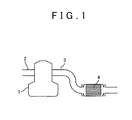
- a reference numeral 1 denotes a body of an internal combustion engine
- a reference numeral 2 denotes an intake passage
- a reference numeral 3 denotes an exhaust passage
- a reference numeral 4 denotes an exhaust gas purification filter that is arranged within the exhaust passage 3.
- the exhaust gas purification filter 4 is constructed of a wall-flow particulate filter.
- the internal combustion engine is constructed of a compression-ignition internal combustion engine.
- the internal combustion engine is constructed of a spark-ignition internal combustion engine.
- FIGs. 2A and 2B show a structure of the particulate filter 4.
- FIG. 2A shows a front view of the particulate filter 4
- FIG. 2B shows a side sectional view of the particulate filter 4.
- the particulate filter 4 has a honeycomb structure, and includes a plurality of exhaust flow passages 5i, 5o extending parallel to each other, and partitions 6 that separate the exhaust flow passages 5i, 5o from each other.
- the exhaust flow passages 5i, 5o are constructed of exhaust gas inflow passages 5i with their upstream ends opened and with their downstream ends closed by plugs 7d, and exhaust gas outflow passages 5o with their upstream ends closed by plugs 7u and with their downstream ends opened.
- hatched portions show the plugs 7u.
- the exhaust gas inflow passages 5i and the exhaust gas outflow passages 5o are alternately arranged with the partitions 6, which are thin walls, interposed therebetween.
- the exhaust gas inflow passages 5i and the exhaust gas outflow passages 5o are arranged such that each of the exhaust gas inflow passages 5i is surrounded by four exhaust gas outflow passages 5o, and each of the exhaust gas outflow passages 5o is surrounded by four exhaust gas inflow passages 5i.
- the exhaust flow passages are constructed of the exhaust gas inflow passages with their upstream ends and downstream ends opened, and the exhaust gas outflow passages with their upstream ends closed by plugs and with their downstream ends opened.
- each of the partitions 6 is divided into a coated zone CZ and a non-coated zone NCZ that is positioned on the downstream side of the coated zone CZ.
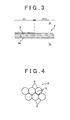
- a surface of a base 6s of the partition 6 is covered with a coating layer 8.
- a surface of the partition base 6s is not covered with the coating layer 8 described above.
- the coating layer 8 is provided on one surface of the partition base 6s, which faces the exhaust gas inflow passage 5i. No coating layer 8 is provided on one surface of the partition base 6s, which faces the exhaust gas outflow passage 5o. In another embodiment, the coating layer 8 is provided on one surface of the partition base 6s, which faces the exhaust gas outflow passage 5o. No coating layer 8 is provided on one surface of the partition base 6s, which faces the exhaust gas inflow passage 5i. In yet another embodiment, the coating layer 8 is provided on each of both surfaces of the partition base 6s, which respectively face the exhaust gas inflow passage 5i and the exhaust gas outflow passage 5o.
- the upstream edge of each coated zone CZ substantially coincides with the upstream end of each partition 6. In another embodiment, the upstream edge of each coated zone CZ is positioned on the downstream side of the upstream end of each partition 6. In the embodiment shown in FIG. 2B , the downstream edge of each non-coated zone NCZ substantially coincides with the downstream end of each partition 6. In another embodiment, the downstream edge of each non-coated zone NCZ is positioned on the upstream side of the downstream end of each partition 6.
- the partition base 6s is formed from a porous material that is, for example, ceramics such as cordierite, silicon carbide, silicon nitride, zirconia, titania, alumina, silica, mullite, lithium aluminum silicate, and zirconium phosphate.
- ceramics such as cordierite, silicon carbide, silicon nitride, zirconia, titania, alumina, silica, mullite, lithium aluminum silicate, and zirconium phosphate.
- the coating layer 8 is formed from a large number of particles 9, and includes a large number of voids or pores 10 between the particles 9.
- the coating layer 8 is porous. Therefore, as shown by arrows in FIG. 2B , exhaust gas first flows into the exhaust gas inflow passages 5i, then passes through the surrounding partitions 6, and flows out into the exhaust gas outflow passages 5o adjacent to the exhaust gas inflow passages 5i.
- the particles 9 are made of metal having an oxidizing function. Platinum group metal such as platinum (Pt), rhodium (Rh), or palladium (Pd) can be used as the metal having an oxidizing function.
- the particles 9 are made of ceramic that is similar to the one used for the partition base 6s. In yet another embodiment, the particles 9 are made of one or both of ceramic and metal.
- the average pore diameter of the partition base 6s is set to 25 ⁇ m or more and 100 ⁇ m or less. It has been found by the inventors that most of the ash contained in exhaust gas can pass through the partitions 6 when the average pore diameter of the partition base 6s is 25 ⁇ m or more. Thus, in other words, the pore diameter of the partition 6 is set such that the ash contained in exhaust gas can pass through each partition 6 in the non-coated zone NCZ. In view of the fact that the average particle diameter of particulate matter is smaller than that of the ash, it can also be said that the pore diameter of the partition 6 is set such that particulate matter and the ash can pass through the partition 6 in the non-coated zone NCZ.
- the average pore diameter of the coating layer 8 is set smaller than the average pore diameter of the partition base 6s. Specifically, the average pore diameter of the coating layer 8 is set such that the coating layer 8 can collect the particulate matter contained in exhaust gas. Further, the average diameter of the particles 9 (secondary particles) is set to 1 ⁇ m or more and 10 ⁇ m or less. When the average diameter of the particles 9 is less than 1 ⁇ m, the amount of the particulate matter which passes through the coating layer 8 exceeds the allowable amount. Further, if the average diameter of the particles 9 is more than 10 ⁇ m, the pressure loss of the particulate filter 4 or the coating layer 8 exceeds the allowable value.
- the average pore diameter of the partition base means a median diameter (50% of the diameter) of the pore diameter distribution obtained by the mercury penetration method
- the average diameter of particles means a median diameter (50% of the diameter) of the volume-based particle size distribution obtained by a laser diffraction and scattering method.
- Particulate matter that is formed mainly from solid carbon is contained in exhaust gas. This particulate matter is collected on the particulate filter 4.
- the ash is also contained in exhaust gas.
- the ash is collected by the particulate filter 4, together with the particulate matter. It has been confirmed by the inventors of the invention that the ash is formed mainly from calcium salt, such as calcium sulfate (CaSO 4 ) and zinc calcium phosphate Ca 19 Zn 2 (PO 4 ) 14 .
- Calcium (Ca), zinc (Zn), phosphorus (P), and the like are derived from engine lubricant oil.
- Sulfur (S) is derived from fuel.
- CaSO 4 calcium sulfate
- the engine lubricant oil flows into a combustion chamber 2 and is burnt in the chamber, and calcium (Ca) in the lubricant oil is bonded to sulfur (S) in the fuel, thereby producing calcium sulfate (CaSO 4 ).
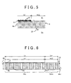
- the coated zone CZ is provided on the upstream side of each partition 6, and the non-coated zone NCZ is provided on the downstream side of each partition 6. Consequently, as shown in FIG. 5 , particulate matter 20 is collected by the partition 6 in the coated zone CZ on the upstream side, and the ash 21 passes through the partition 6 in the non-coated zone NCZ on the downstream side. Therefore, the ash can be suppressed from being deposited on the particulate filter 4 while particulate matter is suppressed from passing through the particulate filter 4. In other words, an increase in pressure loss of the particulate filter 4, caused by the ash, can be suppressed while particulate matter is reliably collected.
- a PM removing process is performed to remove particulate matter from the particulate filter 4.
- the PM removing process for example, while the particulate filter is maintained in an oxidizing atmosphere, the temperature of the particulate filter is increased, and therefore the particulate matter is burnt.
- the particulate matter reaches the non-coated zone NCZ without being collected by the partition 6 in the coated zone CZ, the particulate matter passes through the partition 6 in the non-coated zone NCZ and is discharged into the atmosphere.
- the partition 6 is formed such that a passage resistance of a partition portion located in the coated zone CZ, the passage resistance being in a thickness direction of the partition portion located in the coated zone CZ, is lower than a passage resistance of a partition portion located in the non-coated zone NCZ, the passage resistance being in a thickness direction of the partition portion located in the non-coated zone NCZ.
- FIG. 6 schematically shows the partition 6 of the embodiment shown in FIG. 2B .
- Pc indicates pores formed in a partition base portion 6sc located in the coated zone CZ while Pnc indicates pores formed in a partition base portion 6snc located in the non-coated zone NCZ.
- the average pore diameter and the pore density of the partition base portion 6sc located in the coated zone CZ are substantially equal to the average pore diameter and the pore density of the partition base portion 6snc located in the non-coated zone NCZ, respectively.
- the pore density of the partition base portion is the number of the pores per unit volume of the partition base portion and is also expressed by a porosity of the partition base portion.
- a thickness dc of the partition base portion 6sc located in the coated zone CZ and a thickness dnc of the partition base portion 6snc located in the non-coated zone NCZ are also substantially equal to each other.
- a length Lc of the coated zone CZ in its longitudinal direction is longer than a length Lnc of the non-coated zone NCZ in its longitudinal direction.
- the length Lc of the partition base portion 6sc located in the coated zone CZ is longer than the length Lnc of the partition base portion 6snc located in the non-coated zone NCZ.
- the number of the pores in the partition base portion 6sc located in the coated zone CZ is larger than the number of the pores in the partition base portion 6snc located in the non-coated zone NCZ.
- the passage resistance of the partition portion located in the coated zone CZ becomes lower than the passage resistance of the partition portion located in the non-coated zone NCZ.
- a coating layer is not provided in the non-coated zone NCZ.
- another coating layer which is different from the coating layer 8 is provided in the non-coated zone NCZ.
- the average pore diameter of the partition base portion 6snc located in the non-coated zone NCZ in the state in which the other coating layer is provided is substantially equal to the average pore diameter of the partition base portion 6sc located in the coated zone CZ, and is set to 25 ⁇ m or more and 100 ⁇ m or less.
- the other coating layer is formed of a catalytic coating layer which carries metal having an oxidizing function, for example. As a result, particulate matter that has reached the non-coated zone NCZ can be oxidized and removed easily.
- FIG. 7 shows yet another embodiment of the invention. Hereinafter, the differences from the embodiment shown in FIG. 6 will be described.
- the length of the coated zone CZ in its longitudinal direction is substantially equal to the length of the non-coated zone NCZ in its longitudinal direction
- the average pore diameter and the thickness of the partition base portion 6sc located in the coated zone CZ are substantially equal to the average pore diameter and the thickness of the partition base portion 6snc located in the non-coated zone NCZ, respectively.
- the pore density of the partition base portion 6sc located in the coated zone CZ is higher than the pore density of the partition base portion 6snc located in the non-coated zone NCZ.
- the number of the pores in the partition base portion 6sc is larger than the number of the pores in the partition base portion 6snc. Accordingly, the passage resistance of the partition portion located in the coated zone CZ is lower than the passage resistance of the partition portion located in the non-coated zone NCZ.
- the pores are formed in the partition base as follows. That is, opening agent is mixed with the material of the base, and then the base is burnt. At this time, the opening agent is burnt away, and therefore the pores are formed in the partition base.
- the pore density is increased by increasing the amount of the opening agent to be mixed with the base material.
- FIG. 8 shows yet another embodiment of the invention. Hereinafter, differences from the embodiment shown in FIG. 6 will be described.
- the length of the coated zone CZ in its longitudinal direction is substantially equal to the length of the non-coated zone NCZ in its longitudinal direction
- the pore density and the thickness of the partition base portion 6sc located in the coated zone CZ are substantially equal to the pore density and the thickness of the partition base portion 6snc located in the non-coated zone NCZ, respectively.
- the average pore diameter of the partition base portion 6sc located in the coated zone CZ is larger than the average pore diameter of the partition base portion 6snc located in the non-coated zone NCZ.
- FIG. 9 shows yet another embodiment of the invention. Hereinafter, differences from the embodiment shown in FIG. 8 will be described.
- a partition is prepared in which the length of the coated zone CZ in its longitudinal direction is substantially equal to the length of the non-coated zone NCZ in its longitudinal direction, and the average pore diameter, the pore density, and the thickness of the partition base portion 6sc located in the coated zone CZ are substantially equal to the average pore diameter, the pore density, and the thickness of the partition base portion 6snc located in the non-coated zone NCZ, respectively.
- an additional coating layer CP is formed on the internal wall surface of each pore Pnc in the partition base portion 6snc located in the non-coated zone NCZ but an additional coating layer CP is not formed on the internal wall surface of each pore Pc in the partition base portion 6snc located in the coated zone NCZ.
- the average pore diameter of the partition base portion 6sc located in the coated zone CZ is set to be larger than the average pore diameter of the partition base portion 6snc located in the non-coated zone NCZ.
- the additional coating layer CP carries catalyst.
- FIG. 10 shows yet another embodiment of the invention. Hereinafter, differences from the embodiment shown in FIG. 6 will be described.
- the length of the coated zone CZ in its longitudinal direction is substantially equal to the length of the non-coated zone NCZ in its longitudinal direction
- the average pore diameter and the pore density of the partition base portion 6sc located in the coated zone CZ are substantially equal to the average pore diameter and the pore density of the partition base portion 6snc located in the non-coated zone NCZ, respectively.
- a thickness dc of the partition base portion 6sc located in the coated zone CZ is smaller than a thickness dnc of the partition base portion 6snc located in the non-coated zone NCZ.
- the length of the coated zone CZ in its longitudinal direction is set longer than the length of the non-coated zone NCZ in its longitudinal direction while the pore density of the partition base portion located in the coated zone CZ is set higher than the pore density of the partition base portion 6snc located in the non-coated zone NCZ.
- the passage resistance of the partition portion located in the coated zone CZ in its thickness direction depends on not only the passage resistance of the partition base portion 6sc located in the coated zone CZ in its thickness direction, but also the passage resistance of the coating layer 8 in its thickness direction.
- the passage resistance of the partition portion located in the coated zone CZ in its thickness direction is not always lower than the passage resistance of the partition portion located in the non-coated zone NCZ in its thickness direction, even if a length Lc of the coated zone CZ in its longitudinal direction is longer than a length Lnc of the non-coated zone NCZ in its longitudinal direction.
- FIG. 6 for example, the passage resistance of the partition portion located in the coated zone CZ in its thickness direction is not always lower than the passage resistance of the partition portion located in the non-coated zone NCZ in its thickness direction, even if a length Lc of the coated zone CZ in its longitudinal direction is longer than a length Lnc of the non-coated zone NCZ in its longitudinal direction.
- the passage resistance of the partition portion located in the coated zone CZ in its thickness direction is not always lower than the passage resistance of the partition portion located in the non-coated zone NCZ in its thickness direction, even if a thickness dc of the partition base portion 6sc located in the coated zone CZ is smaller than a thickness of the partition base portion 6snc located in the non-coated zone NCZ.
- the passage resistance of the partition portion located in the coated zone CZ in its thickness direction needs to be lower than the passage resistance of the partition portion located in the non-coated zone NCZ in its thickness direction.
Landscapes
- Chemical & Material Sciences (AREA)
- Engineering & Computer Science (AREA)
- Chemical Kinetics & Catalysis (AREA)
- Materials Engineering (AREA)
- Organic Chemistry (AREA)
- Physics & Mathematics (AREA)
- Geometry (AREA)
- Combustion & Propulsion (AREA)
- General Engineering & Computer Science (AREA)
- Mechanical Engineering (AREA)
- General Chemical & Material Sciences (AREA)
- Environmental & Geological Engineering (AREA)
- Oil, Petroleum & Natural Gas (AREA)
- Biomedical Technology (AREA)
- Health & Medical Sciences (AREA)
- Analytical Chemistry (AREA)
- Processes For Solid Components From Exhaust (AREA)
- Filtering Of Dispersed Particles In Gases (AREA)
- Nanotechnology (AREA)
- Filtering Materials (AREA)
- Catalysts (AREA)
- Exhaust Gas Treatment By Means Of Catalyst (AREA)
- Life Sciences & Earth Sciences (AREA)
- Geology (AREA)
Abstract
Description
- The present invention relates to an exhaust gas purification filter.
- A compression-ignition internal combustion engine in which a particulate filter that collects particulate matter in exhaust gas is arranged within an exhaust passage has been known. The particulate filter includes exhaust gas inflow passages and exhaust gas outflow passages that are alternately arranged, and porous partitions that separate the exhaust gas inflow passages and the exhaust gas outflow passages from each other. A downstream end of each exhaust gas inflow passage is closed by a downstream-side plug and an upstream end of each exhaust gas outflow passage is closed by an upstream-side plug. Therefore, exhaust gas first flows into the exhaust gas inflow passages, then passes through the surrounding partitions, and flows out into the adjacent exhaust gas outflow passages. As a result, particulate matter in the exhaust gas is collected on the partitions and is thus suppressed from being released into the atmosphere.
- However, if the amount of particulate matter collected by the particulate filter increases, pressure loss of the particular filter increases gradually. Consequently, the engine output may be decreased. Thus, in this internal combustion engine, a PM removing process, in which the temperature of the particulate filter is increased while the particulate filter is maintained in an oxidizing atmosphere, is performed to burn the particulate matter, thereby removing it from the particulate filter.
- By the way, a non-combustible component called "ash" is contained in exhaust gas. The ash is collected along with the particulate matter on the particulate filter. However, even if the PM removing process is performed, the ash is not burnt or vaporized but remains on the particulate filter. Thus, as the operating time of the engine becomes longer, the amount of the ash collected on the particulate filter increases gradually, and the pressure loss increases gradually in the particulate filter. Consequently, output of the engine may decrease even if the PM removing process is repeatedly performed.
- In view of this, a particulate filter in which a through-hole is formed in each downstream-side plug to allow the ash to flow out of the particulate filter through the through-holes has been known (see Patent Literature 1). In the Patent Literature 1, as the operating time of the engine becomes longer, the through-holes are blocked by particulate matter. When the through-holes are blocked, the particulate filter can collect particulate matter in the same manner as a conventional particulate filter that does not have any through-holes. Next, after a PM removing process is performed, the particulate matter blocking the through-hole is removed and thus the through-holes are opened. As a result, the ash on the particulate filter is discharged from the particulate filter through the through-holes.
- PATENT LITERATURE 1: Japanese Patent Application Publication No.
2004-130229 - However, according to the Patent Literature 1, particulate matter flows out of the particulate filter through the through-holes during a period from the start of the operation of the engine or the end of the PM removing process until blocking of the through-holes. Further, in the Patent Literature 1, because the diameter of each through-hole is set to 0.2 mm or more, a considerable amount of time is required for the through-holes having such a large diameter to be closed by particulate matter. This means that quite a large amount of the particulate matter flows out of the particulate filter through the through-holes.
- An object of the invention is to provide an exhaust gas purification filter that can suppress an increase in pressure loss of the exhaust gas purification filter caused by the ash while reliably collecting particulate matter.
- The invention provides an exhaust gas purification filter that is suitable for arrangement in an exhaust passage of an internal combustion engine and for collecting particulate matter contained in exhaust gas, the exhaust gas purification filter comprising: exhaust gas inflow passages and exhaust gas outflow passages that are arranged alternately; and porous partitions that separate the exhaust gas inflow passages and the exhaust gas outflow passages from each other, wherein each of the partitions is divided into a coated zone in which a surface of a partition base is coated with a coating layer having a smaller average pore diameter than an average pore diameter of the partition base and a non-coated zone that is located on a downstream side of the coated zone and in which a surface of the partition base is not coated with the coating layer, wherein a pore diameter of the partitions is set such that ash contained in the exhaust gas is able to pass through the partitions in the non-coated zone, and wherein a passage resistance of a partition portion located in the coated zone, the passage resistance being in a thickness direction of the partition portion located in the coated zone, is lower than a passage resistance of a partition portion located in the non-coated zone, the passage resistance being in a thickness direction of the partition portion located in the non-coated zone.
- Preferably, the number of pores in a partition base portion located in the coated zone is larger than the number of pores in a partition base portion located in the non-coated zone. Further preferably, a length of the coated zone in a longitudinal direction of the coated zone is longer than a length of the non-coated zone in a longitudinal direction of the non-coated zone. Further preferably, a pore density of the partition base portion located in the coated zone is higher than a pore density of the partition base portion located in the non-coated zone.
- Preferably, an average pore diameter of a partition base portion located in the coated zone is larger than an average pore diameter of a partition base portion located in the non-coated zone.
- Preferably, a thickness of a partition base portion located in the coated zone is smaller than a thickness of a partition base portion located in the non-coated zone.
- Preferably, an average pore diameter of the partition base is set to 25 µm or more and 100 µm or less.
- Preferably, the coating layer is formed from metallic particles having an oxidizing function.
- Preferably, an average diameter of particles that form the coating layer is set to 1 µm or more and 10 µm or less.
- The exhaust gas purification filter of the invention can suppress an increase in pressure loss of the exhaust gas purification filter caused by the ash while reliably collecting particulate matter.
-
- [
FIG. 1] FIG. 1 is an overall view of an internal combustion engine according to an embodiment of the invention. - [
FIG. 2A] FIG. 2A is a front view of a particulate filter. - [
FIG. 2B] FIG. 2B is a side cross-sectional view of the particulate filter. - [
FIG. 3] FIG. 3 is a partially-enlarged sectional view of a partition. - [
FIG.4] FIG. 4 is a partially-enlarged sectional view of a coating layer. - [
FIG. 5] FIG. 5 is a schematic view for explaining an operation of the particulate filter. - [
FIG. 6] FIG. 6 is a schematic view of the partition. - [
FIG. 7] FIG. 7 is a schematic view of a partition according to another embodiment of the invention. - [
FIG. 8] FIG. 8 is a schematic view of a partition according to yet another embodiment of the invention. - [
FIG. 9] FIG. 9 is a schematic view of a partition according to yet another embodiment of the invention. - [
FIG. 10] FIG. 10 is a schematic view of a partition according to yet another embodiment of the invention. - With reference to
FIG. 1 , a reference numeral 1 denotes a body of an internal combustion engine, areference numeral 2 denotes an intake passage, areference numeral 3 denotes an exhaust passage, and areference numeral 4 denotes an exhaust gas purification filter that is arranged within theexhaust passage 3. In an embodiment shown inFIG. 1 , the exhaustgas purification filter 4 is constructed of a wall-flow particulate filter. In the embodiment shown inFIG. 1 , the internal combustion engine is constructed of a compression-ignition internal combustion engine. In another embodiment, the internal combustion engine is constructed of a spark-ignition internal combustion engine. -
FIGs. 2A and 2B show a structure of theparticulate filter 4.FIG. 2A shows a front view of theparticulate filter 4, andFIG. 2B shows a side sectional view of theparticulate filter 4. As shown inFIGs. 2A and 2B , theparticulate filter 4 has a honeycomb structure, and includes a plurality ofexhaust flow passages 5i, 5o extending parallel to each other, andpartitions 6 that separate theexhaust flow passages 5i, 5o from each other. In the embodiment shown inFIG 2A , theexhaust flow passages 5i, 5o are constructed of exhaustgas inflow passages 5i with their upstream ends opened and with their downstream ends closed byplugs 7d, and exhaust gas outflow passages 5o with their upstream ends closed byplugs 7u and with their downstream ends opened. InFIG. 2A , hatched portions show theplugs 7u. Thus, the exhaustgas inflow passages 5i and the exhaust gas outflow passages 5o are alternately arranged with thepartitions 6, which are thin walls, interposed therebetween. In other words, the exhaustgas inflow passages 5i and the exhaust gas outflow passages 5o are arranged such that each of the exhaustgas inflow passages 5i is surrounded by four exhaust gas outflow passages 5o, and each of the exhaust gas outflow passages 5o is surrounded by four exhaustgas inflow passages 5i. In another embodiment, the exhaust flow passages are constructed of the exhaust gas inflow passages with their upstream ends and downstream ends opened, and the exhaust gas outflow passages with their upstream ends closed by plugs and with their downstream ends opened. - As shown in
FIG. 2B , each of thepartitions 6 is divided into a coated zone CZ and a non-coated zone NCZ that is positioned on the downstream side of the coated zone CZ. As shown inFIG. 3 , in the coated zone CZ, a surface of abase 6s of thepartition 6 is covered with acoating layer 8. In contrast to this, in the non-coated zone NCZ, a surface of thepartition base 6s is not covered with thecoating layer 8 described above. - In the embodiment shown in
FIG. 3 , thecoating layer 8 is provided on one surface of thepartition base 6s, which faces the exhaustgas inflow passage 5i. Nocoating layer 8 is provided on one surface of thepartition base 6s, which faces the exhaust gas outflow passage 5o. In another embodiment, thecoating layer 8 is provided on one surface of thepartition base 6s, which faces the exhaust gas outflow passage 5o. Nocoating layer 8 is provided on one surface of thepartition base 6s, which faces the exhaustgas inflow passage 5i. In yet another embodiment, thecoating layer 8 is provided on each of both surfaces of thepartition base 6s, which respectively face the exhaustgas inflow passage 5i and the exhaust gas outflow passage 5o. - In the embodiment shown in
FIG. 2B , the upstream edge of each coated zone CZ substantially coincides with the upstream end of eachpartition 6. In another embodiment, the upstream edge of each coated zone CZ is positioned on the downstream side of the upstream end of eachpartition 6. In the embodiment shown inFIG. 2B , the downstream edge of each non-coated zone NCZ substantially coincides with the downstream end of eachpartition 6. In another embodiment, the downstream edge of each non-coated zone NCZ is positioned on the upstream side of the downstream end of eachpartition 6. - The
partition base 6s is formed from a porous material that is, for example, ceramics such as cordierite, silicon carbide, silicon nitride, zirconia, titania, alumina, silica, mullite, lithium aluminum silicate, and zirconium phosphate. - On the other hand, as shown in
FIG. 4 , thecoating layer 8 is formed from a large number ofparticles 9, and includes a large number of voids orpores 10 between theparticles 9. Thus, thecoating layer 8 is porous. Therefore, as shown by arrows inFIG. 2B , exhaust gas first flows into the exhaustgas inflow passages 5i, then passes through the surroundingpartitions 6, and flows out into the exhaust gas outflow passages 5o adjacent to the exhaustgas inflow passages 5i. - In the embodiment shown in
FIG. 4 , theparticles 9 are made of metal having an oxidizing function. Platinum group metal such as platinum (Pt), rhodium (Rh), or palladium (Pd) can be used as the metal having an oxidizing function. In another embodiment, theparticles 9 are made of ceramic that is similar to the one used for thepartition base 6s. In yet another embodiment, theparticles 9 are made of one or both of ceramic and metal. - The average pore diameter of the
partition base 6s is set to 25 µm or more and 100 µm or less. It has been found by the inventors that most of the ash contained in exhaust gas can pass through thepartitions 6 when the average pore diameter of thepartition base 6s is 25 µm or more. Thus, in other words, the pore diameter of thepartition 6 is set such that the ash contained in exhaust gas can pass through eachpartition 6 in the non-coated zone NCZ. In view of the fact that the average particle diameter of particulate matter is smaller than that of the ash, it can also be said that the pore diameter of thepartition 6 is set such that particulate matter and the ash can pass through thepartition 6 in the non-coated zone NCZ. - The average pore diameter of the
coating layer 8 is set smaller than the average pore diameter of thepartition base 6s. Specifically, the average pore diameter of thecoating layer 8 is set such that thecoating layer 8 can collect the particulate matter contained in exhaust gas. Further, the average diameter of the particles 9 (secondary particles) is set to 1µm or more and 10µm or less. When the average diameter of theparticles 9 is less than 1 µm, the amount of the particulate matter which passes through thecoating layer 8 exceeds the allowable amount. Further, if the average diameter of theparticles 9 is more than 10µm, the pressure loss of theparticulate filter 4 or thecoating layer 8 exceeds the allowable value. - In the embodiment of the invention, the average pore diameter of the partition base means a median diameter (50% of the diameter) of the pore diameter distribution obtained by the mercury penetration method, and the average diameter of particles means a median diameter (50% of the diameter) of the volume-based particle size distribution obtained by a laser diffraction and scattering method.
- Particulate matter that is formed mainly from solid carbon is contained in exhaust gas. This particulate matter is collected on the
particulate filter 4. - The ash is also contained in exhaust gas. The ash is collected by the
particulate filter 4, together with the particulate matter. It has been confirmed by the inventors of the invention that the ash is formed mainly from calcium salt, such as calcium sulfate (CaSO4) and zinc calcium phosphate Ca19Zn2 (PO4)14. Calcium (Ca), zinc (Zn), phosphorus (P), and the like are derived from engine lubricant oil. Sulfur (S) is derived from fuel. That is, if calcium sulfate (CaSO4) is taken as an example for the description, the engine lubricant oil flows into acombustion chamber 2 and is burnt in the chamber, and calcium (Ca) in the lubricant oil is bonded to sulfur (S) in the fuel, thereby producing calcium sulfate (CaSO4). - According to the inventors of the invention, it has been confirmed that, when a conventional particulate filter that has an average pore diameter of approximately 10 to 25 µm and that does not include the
coating layer 8, that is, a particulate filter through which the ash can hardly pass, is arranged within the exhaust passage of the engine, particulate matter tends to be deposited more on the upstream portion of thepartition 6 than on the downstream portion of thepartition 6. It has been further confirmed that the ash tends to be deposited more on the downstream portion of thepartition 6 than on the upstream portion of thepartition 6. - Thus, in the embodiment of the invention, the coated zone CZ is provided on the upstream side of each
partition 6, and the non-coated zone NCZ is provided on the downstream side of eachpartition 6. Consequently, as shown inFIG. 5 ,particulate matter 20 is collected by thepartition 6 in the coated zone CZ on the upstream side, and theash 21 passes through thepartition 6 in the non-coated zone NCZ on the downstream side. Therefore, the ash can be suppressed from being deposited on theparticulate filter 4 while particulate matter is suppressed from passing through theparticulate filter 4. In other words, an increase in pressure loss of theparticulate filter 4, caused by the ash, can be suppressed while particulate matter is reliably collected. - In the embodiment shown in
FIG. 1 , each time the amount of particulate matter collected on theparticulate filter 4 exceeds the upper limit amount, a PM removing process is performed to remove particulate matter from theparticulate filter 4. In the PM removing process, for example, while the particulate filter is maintained in an oxidizing atmosphere, the temperature of the particulate filter is increased, and therefore the particulate matter is burnt. - By the way, if the particulate matter reaches the non-coated zone NCZ without being collected by the
partition 6 in the coated zone CZ, the particulate matter passes through thepartition 6 in the non-coated zone NCZ and is discharged into the atmosphere. - Thus, in the embodiment of the invention, the
partition 6 is formed such that a passage resistance of a partition portion located in the coated zone CZ, the passage resistance being in a thickness direction of the partition portion located in the coated zone CZ, is lower than a passage resistance of a partition portion located in the non-coated zone NCZ, the passage resistance being in a thickness direction of the partition portion located in the non-coated zone NCZ. As a result, passing of the exhaust gas, which has flowed into the exhaustgas inflow passage 5i, through the partition portion located in the coated zone CZ is facilitated, whereas passing of the exhaust gas, which has flowed into the exhaustgas inflow passage 5i, through the partition portion located in the non-coated zone NCZ is suppressed. Thus, an increase in pressure loss of theparticulate filter 4 caused by the ash can be further suppressed while the particulate matter is collected more reliably. - The detailed description will be made with reference to
FIG. 6. FIG. 6 schematically shows thepartition 6 of the embodiment shown inFIG. 2B . InFIG. 6 , Pc indicates pores formed in a partition base portion 6sc located in the coated zone CZ while Pnc indicates pores formed in a partition base portion 6snc located in the non-coated zone NCZ. As shown inFIG. 6 , the average pore diameter and the pore density of the partition base portion 6sc located in the coated zone CZ are substantially equal to the average pore diameter and the pore density of the partition base portion 6snc located in the non-coated zone NCZ, respectively. The pore density of the partition base portion is the number of the pores per unit volume of the partition base portion and is also expressed by a porosity of the partition base portion. Further, a thickness dc of the partition base portion 6sc located in the coated zone CZ and a thickness dnc of the partition base portion 6snc located in the non-coated zone NCZ are also substantially equal to each other. In addition, in the embodiment shown inFIG. 6 , a length Lc of the coated zone CZ in its longitudinal direction is longer than a length Lnc of the non-coated zone NCZ in its longitudinal direction. In other words, the length Lc of the partition base portion 6sc located in the coated zone CZ is longer than the length Lnc of the partition base portion 6snc located in the non-coated zone NCZ. As a result, the number of the pores in the partition base portion 6sc located in the coated zone CZ is larger than the number of the pores in the partition base portion 6snc located in the non-coated zone NCZ. Thus, the passage resistance of the partition portion located in the coated zone CZ becomes lower than the passage resistance of the partition portion located in the non-coated zone NCZ. - In the embodiment shown in
FIG. 6 , a coating layer is not provided in the non-coated zone NCZ. In another embodiment, another coating layer which is different from thecoating layer 8 is provided in the non-coated zone NCZ. In this case, the average pore diameter of the partition base portion 6snc located in the non-coated zone NCZ in the state in which the other coating layer is provided is substantially equal to the average pore diameter of the partition base portion 6sc located in the coated zone CZ, and is set to 25 µm or more and 100 µm or less. The other coating layer is formed of a catalytic coating layer which carries metal having an oxidizing function, for example. As a result, particulate matter that has reached the non-coated zone NCZ can be oxidized and removed easily. -
FIG. 7 shows yet another embodiment of the invention. Hereinafter, the differences from the embodiment shown inFIG. 6 will be described. - In the embodiment shown in
FIG. 7 , the length of the coated zone CZ in its longitudinal direction is substantially equal to the length of the non-coated zone NCZ in its longitudinal direction, and the average pore diameter and the thickness of the partition base portion 6sc located in the coated zone CZ are substantially equal to the average pore diameter and the thickness of the partition base portion 6snc located in the non-coated zone NCZ, respectively. In addition, the pore density of the partition base portion 6sc located in the coated zone CZ is higher than the pore density of the partition base portion 6snc located in the non-coated zone NCZ. As a result, the number of the pores in the partition base portion 6sc is larger than the number of the pores in the partition base portion 6snc. Accordingly, the passage resistance of the partition portion located in the coated zone CZ is lower than the passage resistance of the partition portion located in the non-coated zone NCZ. - For example, the pores are formed in the partition base as follows. That is, opening agent is mixed with the material of the base, and then the base is burnt. At this time, the opening agent is burnt away, and therefore the pores are formed in the partition base. Thus, the pore density is increased by increasing the amount of the opening agent to be mixed with the base material.
-
FIG. 8 shows yet another embodiment of the invention. Hereinafter, differences from the embodiment shown inFIG. 6 will be described. - In the embodiment shown in
FIG. 8 , the length of the coated zone CZ in its longitudinal direction is substantially equal to the length of the non-coated zone NCZ in its longitudinal direction, and the pore density and the thickness of the partition base portion 6sc located in the coated zone CZ are substantially equal to the pore density and the thickness of the partition base portion 6snc located in the non-coated zone NCZ, respectively. In addition, the average pore diameter of the partition base portion 6sc located in the coated zone CZ is larger than the average pore diameter of the partition base portion 6snc located in the non-coated zone NCZ. As a result, the passage resistance of the partition portion located in the coated zone CZ becomes lower than the passage resistance of the partition portion located in the non-coated zone NCZ. -
FIG. 9 shows yet another embodiment of the invention. Hereinafter, differences from the embodiment shown inFIG. 8 will be described. - In the embodiment shown in
FIG. 9 , a partition is prepared in which the length of the coated zone CZ in its longitudinal direction is substantially equal to the length of the non-coated zone NCZ in its longitudinal direction, and the average pore diameter, the pore density, and the thickness of the partition base portion 6sc located in the coated zone CZ are substantially equal to the average pore diameter, the pore density, and the thickness of the partition base portion 6snc located in the non-coated zone NCZ, respectively. Next, an additional coating layer CP is formed on the internal wall surface of each pore Pnc in the partition base portion 6snc located in the non-coated zone NCZ but an additional coating layer CP is not formed on the internal wall surface of each pore Pc in the partition base portion 6snc located in the coated zone NCZ. As a result, the average pore diameter of the partition base portion 6sc located in the coated zone CZ is set to be larger than the average pore diameter of the partition base portion 6snc located in the non-coated zone NCZ. The additional coating layer CP carries catalyst. -
FIG. 10 shows yet another embodiment of the invention. Hereinafter, differences from the embodiment shown inFIG. 6 will be described. - In the embodiment shown in
FIG. 10 , the length of the coated zone CZ in its longitudinal direction is substantially equal to the length of the non-coated zone NCZ in its longitudinal direction, and the average pore diameter and the pore density of the partition base portion 6sc located in the coated zone CZ are substantially equal to the average pore diameter and the pore density of the partition base portion 6snc located in the non-coated zone NCZ, respectively. In addition, a thickness dc of the partition base portion 6sc located in the coated zone CZ is smaller than a thickness dnc of the partition base portion 6snc located in the non-coated zone NCZ. As a result, the passage resistance of the partition portion located in the coated zone CZ becomes lower than the passage resistance of the partition portion located in the non-coated zone NCZ. - In yet another embodiment, at least two of the embodiments shown in
FIGs. 6 to 10 are combined with each other. For example, the length of the coated zone CZ in its longitudinal direction is set longer than the length of the non-coated zone NCZ in its longitudinal direction while the pore density of the partition base portion located in the coated zone CZ is set higher than the pore density of the partition base portion 6snc located in the non-coated zone NCZ. - The passage resistance of the partition portion located in the coated zone CZ in its thickness direction depends on not only the passage resistance of the partition base portion 6sc located in the coated zone CZ in its thickness direction, but also the passage resistance of the
coating layer 8 in its thickness direction. Thus, in the embodiment shown inFIG. 6 , for example, the passage resistance of the partition portion located in the coated zone CZ in its thickness direction is not always lower than the passage resistance of the partition portion located in the non-coated zone NCZ in its thickness direction, even if a length Lc of the coated zone CZ in its longitudinal direction is longer than a length Lnc of the non-coated zone NCZ in its longitudinal direction. Similarly, in the embodiment shown inFIG. 10 , the passage resistance of the partition portion located in the coated zone CZ in its thickness direction is not always lower than the passage resistance of the partition portion located in the non-coated zone NCZ in its thickness direction, even if a thickness dc of the partition base portion 6sc located in the coated zone CZ is smaller than a thickness of the partition base portion 6snc located in the non-coated zone NCZ. In the invention, the passage resistance of the partition portion located in the coated zone CZ in its thickness direction needs to be lower than the passage resistance of the partition portion located in the non-coated zone NCZ in its thickness direction. -
- 1/ ENGINE BODY
- 3/ EXHAUST PASSAGE
- 4/ PARTICULATE FILTER
- 5i/ EXHAUST GAS INFLOW PASSAGE
- 5o/ EXHAUST GAS OUTFLOW PASSAGE
- 6/ PARTITION
- 8/ COATING LAYER
- CZ/ COATED ZONE
- NCZ/ NON-COATED ZONE
Claims (9)
- An exhaust gas purification filter that is suitable for arrangement in an exhaust passage of an internal combustion engine and for collecting particulate matter contained in exhaust gas, the exhaust gas purification filter comprising:exhaust gas inflow passages and exhaust gas outflow passages that are arranged alternately; andporous partitions that separate the exhaust gas inflow passages and the exhaust gas outflow passages from each other,wherein each of the partitions is divided into a coated zone in which a surface of a partition base is coated with a coating layer having a smaller average pore diameter than an average pore diameter of the partition base and a non-coated zone that is located on a downstream side of the coated zone and in which a surface of the partition base is not coated with the coating layer,wherein a pore diameter of the partitions is set such that ash contained in the exhaust gas is able to pass through the partitions in the non-coated zone, andwherein a passage resistance of a partition portion located in the coated zone, the passage resistance being in a thickness direction of the partition portion located in the coated zone, is lower than a passage resistance of a partition portion located in the non-coated zone, the passage resistance being in a thickness direction of the partition portion located in the non-coated zone.
- The exhaust gas purification filter according to claim 1, wherein the number of pores in a partition base portion located in the coated zone is larger than the number of pores in a partition base portion located in the non-coated zone.
- The exhaust gas purification filter according to claim 2, wherein a length of the coated zone in a longitudinal direction of the coated zone is longer than a length of the non-coated zone in a longitudinal direction of the non-coated zone.
- The exhaust gas purification filter according to claim 2 or 3, wherein a pore density of the partition base portion located in the coated zone is higher than a pore density of the partition base portion located in the non-coated zone.
- The exhaust gas purification filter according to any one of claims 1 to 4, wherein an average pore diameter of a partition base portion located in the coated zone is larger than an average pore diameter of a partition base portion located in the non-coated zone.
- The exhaust gas purification filter according to any one of claims 1 to 5, wherein a thickness of a partition base portion located in the coated zone is smaller than a thickness of a partition base portion located in the non-coated zone.
- The exhaust gas purification filter according to any one of claims 1 to 6, wherein an average pore diameter of the partition base is set to 25 µm or more and 100 µm or less.
- The exhaust gas purification filter according to any one of claims 1 to 7, wherein the coating layer is formed from metallic particles having an oxidizing function.
- The exhaust gas purification filter according to any one of claims 1 to 8, wherein an average diameter of particles that form the coating layer is set to 1 µm or more and 10 µm or less.
Applications Claiming Priority (1)
| Application Number | Priority Date | Filing Date | Title |
|---|---|---|---|
| PCT/JP2012/080770 WO2014083642A1 (en) | 2012-11-28 | 2012-11-28 | Exhaust purification filter |
Publications (2)
| Publication Number | Publication Date |
|---|---|
| EP2927444A1 true EP2927444A1 (en) | 2015-10-07 |
| EP2927444A4 EP2927444A4 (en) | 2016-08-24 |
Family
ID=50827316
Family Applications (1)
| Application Number | Title | Priority Date | Filing Date |
|---|---|---|---|
| EP12889051.4A Withdrawn EP2927444A4 (en) | 2012-11-28 | 2012-11-28 | EXHAUST PURIFYING FILTER |
Country Status (7)
| Country | Link |
|---|---|
| US (1) | US9718026B2 (en) |
| EP (1) | EP2927444A4 (en) |
| JP (1) | JP5975111B2 (en) |
| KR (1) | KR20150079848A (en) |
| CN (1) | CN104812999B (en) |
| BR (1) | BR112015012323A2 (en) |
| WO (1) | WO2014083642A1 (en) |
Families Citing this family (8)
| Publication number | Priority date | Publication date | Assignee | Title |
|---|---|---|---|---|
| JP6158832B2 (en) * | 2012-12-03 | 2017-07-05 | トヨタ自動車株式会社 | Exhaust purification filter |
| JP6007864B2 (en) * | 2013-06-10 | 2016-10-12 | トヨタ自動車株式会社 | Exhaust purification filter |
| JP6635819B2 (en) * | 2016-02-16 | 2020-01-29 | 日本碍子株式会社 | Honeycomb structure |
| JP6690379B2 (en) * | 2016-04-14 | 2020-04-28 | いすゞ自動車株式会社 | PM sensor |
| US10934910B2 (en) * | 2017-03-27 | 2021-03-02 | Cataler Corporation | Exhaust gas cleaning catalyst |
| JP7211893B2 (en) * | 2019-05-24 | 2023-01-24 | トヨタ自動車株式会社 | Exhaust gas purifier |
| JP7381372B2 (en) | 2020-03-12 | 2023-11-15 | トヨタ自動車株式会社 | Exhaust gas purification device |
| JP2022152985A (en) * | 2021-03-29 | 2022-10-12 | 日本碍子株式会社 | honeycomb filter |
Family Cites Families (22)
| Publication number | Priority date | Publication date | Assignee | Title |
|---|---|---|---|---|
| US5258349A (en) * | 1990-11-26 | 1993-11-02 | Catalytica, Inc. | Graded palladium-containing partial combustion catalyst |
| JP4427658B2 (en) | 1998-07-07 | 2010-03-10 | コーニング インコーポレイテッド | Diesel exhaust filter |
| JP4640868B2 (en) | 2001-07-18 | 2011-03-02 | イビデン株式会社 | Filter with catalyst, method for manufacturing the same, and exhaust gas purification system |
| JP4393039B2 (en) | 2001-07-18 | 2010-01-06 | イビデン株式会社 | Filter with catalyst, method for manufacturing the same, and exhaust gas purification system |
| JP2004068635A (en) * | 2002-08-02 | 2004-03-04 | Hino Motors Ltd | How to prevent ash accumulation in particulate filters |
| US7118717B2 (en) * | 2002-09-06 | 2006-10-10 | Engelhard Corporation | Simplified article for carbon monoxide removal |
| JP4172986B2 (en) * | 2002-10-10 | 2008-10-29 | 日本碍子株式会社 | Honeycomb structure, manufacturing method thereof, and exhaust gas purification system using the honeycomb structure |
| JP2004239199A (en) * | 2003-02-07 | 2004-08-26 | Hino Motors Ltd | Particulate filter |
| DE602004011997T2 (en) * | 2003-06-05 | 2009-02-26 | Ibiden Co., Ltd., Ogaki | HONEYCOMB BODY STRUCTURE |
| US7481983B2 (en) * | 2004-08-23 | 2009-01-27 | Basf Catalysts Llc | Zone coated catalyst to simultaneously reduce NOx and unreacted ammonia |
| JP5124177B2 (en) * | 2007-06-13 | 2013-01-23 | 東京窯業株式会社 | Honeycomb structure |
| JP5419371B2 (en) * | 2008-03-17 | 2014-02-19 | 日本碍子株式会社 | Catalyst support filter |
| JP5349108B2 (en) | 2009-03-26 | 2013-11-20 | 日本碍子株式会社 | Honeycomb filter |
| FR2944052B1 (en) | 2009-04-03 | 2011-04-22 | Saint Gobain Ct Recherches | STRUCTURE FOR GAS FILTRATION AND NOX REDUCTION. |
| JP2010269205A (en) * | 2009-05-19 | 2010-12-02 | Toyota Motor Corp | Exhaust gas purification catalyst |
| JP2012077693A (en) * | 2010-10-01 | 2012-04-19 | Mitsubishi Motors Corp | Exhaust emission control device |
| JP2012117487A (en) * | 2010-12-03 | 2012-06-21 | Toyota Central R&D Labs Inc | Particulate filter with catalyst, exhaust gas purification and discharge system, catalyst arrangement part ratio calculation method, and catalyst arrangement part ratio calculation device |
| US8789356B2 (en) * | 2011-07-28 | 2014-07-29 | Johnson Matthey Public Limited Company | Zoned catalytic filters for treatment of exhaust gas |
| EP2832962B1 (en) | 2012-03-30 | 2016-08-17 | Toyota Jidosha Kabushiki Kaisha | Particulate filter |
| EP2873816B1 (en) | 2012-07-12 | 2018-01-17 | Toyota Jidosha Kabushiki Kaisha | Exhaust purification device for internal combustion engine |
| WO2014076767A1 (en) | 2012-11-13 | 2014-05-22 | トヨタ自動車株式会社 | Exhaust purification device for internal combustion engine |
| JP6158832B2 (en) | 2012-12-03 | 2017-07-05 | トヨタ自動車株式会社 | Exhaust purification filter |
-
2012
- 2012-11-28 KR KR1020157013932A patent/KR20150079848A/en not_active Ceased
- 2012-11-28 JP JP2014549692A patent/JP5975111B2/en active Active
- 2012-11-28 CN CN201280077305.1A patent/CN104812999B/en not_active Expired - Fee Related
- 2012-11-28 EP EP12889051.4A patent/EP2927444A4/en not_active Withdrawn
- 2012-11-28 US US14/647,614 patent/US9718026B2/en active Active
- 2012-11-28 WO PCT/JP2012/080770 patent/WO2014083642A1/en not_active Ceased
- 2012-11-28 BR BR112015012323A patent/BR112015012323A2/en not_active IP Right Cessation
Also Published As
| Publication number | Publication date |
|---|---|
| US20150298058A1 (en) | 2015-10-22 |
| US9718026B2 (en) | 2017-08-01 |
| JP5975111B2 (en) | 2016-08-23 |
| CN104812999B (en) | 2018-01-19 |
| CN104812999A (en) | 2015-07-29 |
| BR112015012323A2 (en) | 2017-07-11 |
| EP2927444A4 (en) | 2016-08-24 |
| KR20150079848A (en) | 2015-07-08 |
| WO2014083642A1 (en) | 2014-06-05 |
| JPWO2014083642A1 (en) | 2017-01-05 |
Similar Documents
| Publication | Publication Date | Title |
|---|---|---|
| US9718026B2 (en) | Exhaust gas purification filter | |
| EP2926881B1 (en) | Exhaust purification filter | |
| JP5787031B2 (en) | Particulate filter | |
| JP6007864B2 (en) | Exhaust purification filter | |
| EP1375849B1 (en) | Ceramic honeycomb filter | |
| EP1450015B1 (en) | Honeycomb filter and exhaust gas purification system | |
| WO2008066167A1 (en) | Ceramic honeycomb filter and method for manufacturing the same | |
| EP1870573A1 (en) | Diesel particulate filter having improved thermal durability | |
| EP2921666B1 (en) | Exhaust purification device for internal combustion engine | |
| WO2014178633A1 (en) | Gasoline particulate filter for gasoline direct injection engine | |
| JP5954994B2 (en) | Honeycomb filter | |
| JP2006077672A (en) | Exhaust gas purification filter and exhaust gas purification device | |
| JP2014051888A (en) | Particulate filter | |
| KR100587136B1 (en) | Filter catalyst structure for diesel engine | |
| KR100636051B1 (en) | Particulate matter filter structure for diesel engine | |
| JP6635757B2 (en) | Honeycomb filter | |
| RU2575520C1 (en) | Particulates filter |
Legal Events
| Date | Code | Title | Description |
|---|---|---|---|
| PUAI | Public reference made under article 153(3) epc to a published international application that has entered the european phase |
Free format text: ORIGINAL CODE: 0009012 |
|
| 17P | Request for examination filed |
Effective date: 20150528 |
|
| AK | Designated contracting states |
Kind code of ref document: A1 Designated state(s): AL AT BE BG CH CY CZ DE DK EE ES FI FR GB GR HR HU IE IS IT LI LT LU LV MC MK MT NL NO PL PT RO RS SE SI SK SM TR |
|
| AX | Request for extension of the european patent |
Extension state: BA ME |
|
| DAX | Request for extension of the european patent (deleted) | ||
| RA4 | Supplementary search report drawn up and despatched (corrected) |
Effective date: 20160722 |
|
| RIC1 | Information provided on ipc code assigned before grant |
Ipc: F01N 3/035 20060101ALI20160718BHEP Ipc: B01D 39/20 20060101ALI20160718BHEP Ipc: F01N 3/022 20060101AFI20160718BHEP Ipc: B01D 46/00 20060101ALI20160718BHEP Ipc: F01N 3/023 20060101ALI20160718BHEP |
|
| STAA | Information on the status of an ep patent application or granted ep patent |
Free format text: STATUS: THE APPLICATION IS DEEMED TO BE WITHDRAWN |
|
| 18D | Application deemed to be withdrawn |
Effective date: 20170221 |