EP2927150A1 - Dispensing cap allignment - Google Patents
Dispensing cap allignment Download PDFInfo
- Publication number
- EP2927150A1 EP2927150A1 EP14163362.8A EP14163362A EP2927150A1 EP 2927150 A1 EP2927150 A1 EP 2927150A1 EP 14163362 A EP14163362 A EP 14163362A EP 2927150 A1 EP2927150 A1 EP 2927150A1
- Authority
- EP
- European Patent Office
- Prior art keywords
- dispenser
- cap
- longitudinal axis
- seat
- container
- Prior art date
- Legal status (The legal status is an assumption and is not a legal conclusion. Google has not performed a legal analysis and makes no representation as to the accuracy of the status listed.)
- Withdrawn
Links
Images





Classifications
-
- B—PERFORMING OPERATIONS; TRANSPORTING
- B65—CONVEYING; PACKING; STORING; HANDLING THIN OR FILAMENTARY MATERIAL
- B65D—CONTAINERS FOR STORAGE OR TRANSPORT OF ARTICLES OR MATERIALS, e.g. BAGS, BARRELS, BOTTLES, BOXES, CANS, CARTONS, CRATES, DRUMS, JARS, TANKS, HOPPERS, FORWARDING CONTAINERS; ACCESSORIES, CLOSURES, OR FITTINGS THEREFOR; PACKAGING ELEMENTS; PACKAGES
- B65D41/00—Caps, e.g. crown caps or crown seals, i.e. members having parts arranged for engagement with the external periphery of a neck or wall defining a pouring opening or discharge aperture; Protective cap-like covers for closure members, e.g. decorative covers of metal foil or paper
- B65D41/02—Caps or cap-like covers without lines of weakness, tearing strips, tags, or like opening or removal devices
-
- B—PERFORMING OPERATIONS; TRANSPORTING
- B65—CONVEYING; PACKING; STORING; HANDLING THIN OR FILAMENTARY MATERIAL
- B65D—CONTAINERS FOR STORAGE OR TRANSPORT OF ARTICLES OR MATERIALS, e.g. BAGS, BARRELS, BOTTLES, BOXES, CANS, CARTONS, CRATES, DRUMS, JARS, TANKS, HOPPERS, FORWARDING CONTAINERS; ACCESSORIES, CLOSURES, OR FITTINGS THEREFOR; PACKAGING ELEMENTS; PACKAGES
- B65D41/00—Caps, e.g. crown caps or crown seals, i.e. members having parts arranged for engagement with the external periphery of a neck or wall defining a pouring opening or discharge aperture; Protective cap-like covers for closure members, e.g. decorative covers of metal foil or paper
- B65D41/02—Caps or cap-like covers without lines of weakness, tearing strips, tags, or like opening or removal devices
- B65D41/04—Threaded or like caps or cap-like covers secured by rotation
- B65D41/0471—Threaded or like caps or cap-like covers secured by rotation with means for positioning the cap on the container, or for limiting the movement of the cap, or for preventing accidental loosening of the cap
Definitions
- the present invention relates to dispenser having caps and more particularly to a technology for a correct alignment of a dispensing cap on a container of the dispenser.
- EP 0 117 722 A2 relates to a dispenser comprising a cap which is provided with an axially extending stop for orientating the cap with respect to a container which engages with a radial abutment of a seat for orientating the cap with respect to the seat.
- US 4,093,096 A relates to a dispenser comprising a bottle and a cap which has a radial projection towards an axis of the dispenser engaging into a thread of a bottle neck.
- the abutment/stopper surface will undergo wear due to its provision from plastics. Therefore, the final position of the cap is not permanently defined but will shifted or be removed during the lifetime so that a correct alignment onto a container of a dispenser is not ensured throughout the lifetime of the dispenser and the cap.
- the cap and the seat are formed such that guiding surfaces thereof allow to move the cap to a certain position where the cap is correctly orientated without the necessity of a provision of an abutment/stopper surface. This means, the cap may be moved to its final position which is not defined by an additional constructional member.
- a particularly specific embodiment of the present invention may differ in the number of allowable rotation directions and the number of defined final positions for the cap. Due to the geometric formation of the surfaces, the cap is not only correctly guided in the rotational direction but also in the axial direction such that a deviation from the axis at the final position is not possible even if the cap is disposed inclined with respect to the seat at the beginning of rotating the same.
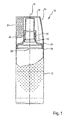
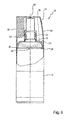
- Fig. 1 shows a longitudinal sectional view of a first embodiment of the present invention.
- Fig. 1 shows a dispenser 10 suitable for storing cosmetic products.
- the dispenser 10 comprises a container 12 and a dispenser cap 14 configured to be seated onto the container 12.
- the container 12 may be a bottle made of plastics and defines a longitudinal axis 16.
- the container 12 comprises at an upper end 18 a threaded neck 20 through which the longitudinal axis 16 extends.
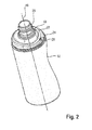
- the container 12 comprises a seat 22 at the upper end 18 on which the cap 14 may be seated, and a wall portion 24, which may be cylindrical and may extend parallel with respect to the longitudinal axis 16.
- the wall portion 24 is coaxially arranged with respect to the longitudinal axis 16 and the longitudinal axis 16 may extend through a center of the wall portion 24.
- the seat 22 is defined as a portion connecting the neck 20 and the wall portion 24.
- the seat 22 has a continuously varying height in an axial direction defined by the longitudinal axis 16 of the container 12.
- the axial height decreases such that only at a certain angle in an circumferential direction around the longitudinal axis 16 the axial height is minimal and increases again towards other angles.
- the seat 22 may be formed similar to a inclined plane which is wound around the longitudinal axis 16 in two directions and is inclined with respect to itself.
- the axial height is minimal at a radial outer position close to the wall portion 24.
- a groove 26 is provided.
- the groove 26 may be formed like a recess and may extend in a radial direction towards the longitudinal axis 16.
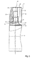
- the cap 14 comprises a top wall 28 and a side wall 30 protruding from the top wall 28.
- a plurality of wings 32 is provided which extend in a radial inner direction.
- three wings 32 may be provided which may be evenly arranged in a circumferential direction.
- At least one of the wings 32 is longer in the direction of the longitudinal axis than the remaining wings 32.
- This specific wing may be called an extended wing 34 hereinafter.
- the extended wing 34 extends to a lower rim 36 of the cap 14, which is opposite to the top wall 28, and flushes therewith.
- the cap 14 is disposed on the seat 22 and the extended wing 34 engages a portion of the seat 22 having a greater axial height than the minimal axial height, the lower rim 36 and the cap 14 are spaced apart from the wall portion 24 of the container.
- the cap may be seated onto the seat 22 in its final position.
- an orientation for the cap 14 when axially positioning the cap 14 onto the seat 22 is provided.
- the cap 22 is automatically guided by axial contact of the cap's lower rim 36 and the seat 20 into one pre-defined position where the extended wing 34 is positioned in the groove 26 even if the cap 14 is disposed in an inclined state with respect to the longitudinal axis 16 of the dispenser 10. Accordingly, the seat 22 provides a guiding surface for the cap 14.
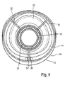
- Fig. 5 which is a cross-sectional view perpendicular to the longitudinal axis 16, shows the cap 14 with the wings 32 and the extended wing 34 engaging the groove 26.
- the lower rim 36 and the seat 22 are not formed so as to have a thread which provides a guiding of the cap 14 for correctly orientating the same onto the container 12 but due to the specific geometric formation of the seat 22, the cap is automatically guided into its final position when rotating the cap 14.
- the cap 14 even if the cap 14 is positioned onto the upper end of the seat 22 in a tilted manner with respect to the longitudinal axis 16 of the dispenser 10, the cap 14 will be correctly oriented when rotating in a circumferential direction around the longitudinal axis 16 of the dispenser 10 and guided towards the final position.
- the cap 14 may be rotated in two circumferential directions, i.e. clockwise and counter-clockwise.
- the cap 14 slides with the extended wing 34 on the guide surface of the seat 22.
- the cap 14 approaches the seat 22 depending on the rotation angle and rotation position, respectively. Accordingly, the cap 14 may be moved from a tilted orientation into an axially aligned orientation during rotating the cap 14 on the seat 22 by means of the guiding surfaces provided by the specific design of the seat 22 and the extended wing 24 of the cap 14 which cooperate.
- Fig. 6 shows a longitudinal sectional view of a second embodiment of the present invention, wherein only the differences from the first embodiment will be described and same constructional members are provided with the same reference numerals.
- the seat 22 and is oval if seen in an axial direction of the longitudinal axis 16.
- Fig. 7 which is a perspective view of the container 12 without the cap 14, an axial height of the seat 22 continuously varies along different angles in the circumferential direction around the longitudinal axis 16 of the dispenser 10, thereby providing an orientation for the cap 14.
- the course of the axial height of the seat 22 as a function of the angle is continuously varying and comprises two minima and two maxima leading to two symmetric engaging positions, which may be defined at 0° and 180° in a circumferential direction around the longitudinal axis 16 of the dispenser 10 by means of two grooves 26.
- the cap 14 may be the same as explained with respect to the first embodiment. With the oriented guidance provided by the specific geometric shape of the seat 22 and the extended wing 34, even if the cap 14 is not correctly positioned on the seat as shown in Fig. 8 , the cap 14 is automatically guided towards one of the grooves 26 of the seat 22 as shown in Fig. 9 .
- the cap 14 may be rotated in two circumferential directions, i.e. clockwise and counter-clockwise.
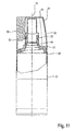
- Fig. 11 shows a longitudinal sectional view of a third embodiment of the present invention, wherein only the differences from the first embodiment will be described and the same constructional members are provided with the same reference numerals.
- the seat 22 comprises a radial surface area having an axial height in a direction of the longitudinal axis 16 of the dispenser 10, which follows a helix around the longitudinal axis 16 of the dispenser 10
- Fig. 12 which is a perspective view of the container 12 without the cap 14. This provides a guidance in form of a radial surface which may be similar to an inclined plane and provides an angular orientation for the cap 14.
- the cap 14 is automatically guided towards one defined position when rotated around the longitudinal axis 16 of the dispenser 10 as shown in Fig. 14 , which may be defined at the end of the helical surface of the seat 22 closest to the wall portion 24 of the container 12.
- the groove 26 of the third embodiment may be smaller than the groove 26 of the first embodiment because the helical guiding surface of the seat 22 includes an abutment surface 38 extending in an upright direction from an radial outer portion of the seat 22 close to the wall portion 24 and adjacent the groove 26.
- cap 14 may be rotated only in one circumferential direction, i.e. counter-clockwise in the view of Fig. 12 .
- cap 14 and the seat 22 are formed such that guiding surfaces thereof allow to move the cap 14 to a certain position where the cap 14 is correctly oriented onto the container 12 without the necessity of a provision of an abutment or stopper surface. i.e. the cap 14 may be moved to its final position which is not defined by an additional constructional member. Particularly, the guiding function may be supported by an extended wing 34 of the cap 14.
- the three embodiments differ in the number of allowable rotation directions for the cap 14 and the number of defined final positions for the cap 14. Further, due to the geometric formation of the surfaces of the seat 22, the cap 14 is not only correctly guided in the rotational direction but also in the axial direction, i.e.
- the cap 14 may be positioned onto the seat 22 in a gas tight and/or liquid tight manner.
- the cap 14 may additionally comprise an inner skirt having a thread corresponding to the thread of the neck 20 of the container 12.
- the dispenser according to the invention can be used to store liquid, particularly volatile liquid, gel or powdered products of any description but is more desirably employed for cosmetics, toiletries and other household products.
- examples of such products are perfume, eau de toilette, talcum powder, shower gel, foam bath product, shampoo, make-up products, sunscreen products, suntan products and dishwashing liquid.
Landscapes
- Engineering & Computer Science (AREA)
- Mechanical Engineering (AREA)
- Closures For Containers (AREA)
Abstract
Description
- The present invention relates to dispenser having caps and more particularly to a technology for a correct alignment of a dispensing cap on a container of the dispenser.
-
EP 0 117 722 A2 relates to a dispenser comprising a cap which is provided with an axially extending stop for orientating the cap with respect to a container which engages with a radial abutment of a seat for orientating the cap with respect to the seat. -
US 4,093,096 A relates to a dispenser comprising a bottle and a cap which has a radial projection towards an axis of the dispenser engaging into a thread of a bottle neck. - According to the above prior art, the abutment/stopper surface will undergo wear due to its provision from plastics. Therefore, the final position of the cap is not permanently defined but will shifted or be removed during the lifetime so that a correct alignment onto a container of a dispenser is not ensured throughout the lifetime of the dispenser and the cap.
- Accordingly, it is an object of the present invention to provide a dispenser allowing to correctly orientate the cap and the seat.
- This object is solved by the present invention in that the cap and the seat are formed such that guiding surfaces thereof allow to move the cap to a certain position where the cap is correctly orientated without the necessity of a provision of an abutment/stopper surface. This means, the cap may be moved to its final position which is not defined by an additional constructional member.
- These and other advantages and features of the various embodiments of the invention disclosed herein, will be made more apparent from the description, drawings and claims that follow.
- Summarizing the ideas of the present invention, the following items are preferred:
- Item 1: The dispenser for dispensing a cosmetic product, comprises a container defining a longitudinal axis, a cap configured to be disposed on the container, a seat provided at the container, wherein the seat is shaped so as to have a surface with a continuously varying axial height in a circumferential direction around the longitudinal axis.
- Item 2: The dispenser of item 1, wherein at a certain angle in an circumferential direction around the longitudinal axis the axial height may be minimal and increases again towards other angles.
- Item 3: The dispenser of item 1, wherein an axial height of the seat may continuously vary along different angles in a circumferential direction around the longitudinal axis of the dispenser and may comprise two minima and two maxima leading to two symmetric engaging positions.
- Item 4: The dispenser of item 3, wherein the minima and the maxima of the axial height may be defined at opposite positions in a circumferential direction around the longitudinal axis of the dispenser.
- Item 5: The dispenser of item 1, wherein the seat may comprise a radial surface area having an axial height in a direction of the longitudinal axis of the dispenser which follows a helix around the longitudinal axis of the dispenser.
- Item 6: The dispenser of item 1, wherein the surface of the seat may comprise at least one groove positioned close to a wall portion of the container.
- Item 7: The dispenser of item 6, wherein the cap may comprise a wing adapted to engage the at least one groove.
- Item 8: The dispenser of item 7, wherein the cap may comprise a plurality of wings, wherein one of the wings is longer in the direction of the longitudinal axis than the remaining wings and adapted to engage the at least one groove.
- A particularly specific embodiment of the present invention may differ in the number of allowable rotation directions and the number of defined final positions for the cap. Due to the geometric formation of the surfaces, the cap is not only correctly guided in the rotational direction but also in the axial direction such that a deviation from the axis at the final position is not possible even if the cap is disposed inclined with respect to the seat at the beginning of rotating the same.
-
- Fig. 1
- is a schematic view of a first embodiment according to the present invention.
- Fig. 2
- is a perspective view of the container without the cap.
- Fig. 3
- is a longitudinal sectional view of the dispenser before the cap is correctly seated onto the container.
- Fig. 4
- is a longitudinal sectional view of the dispenser after the cap is correctly seated onto the container, wherein the container is rotated 90 ° around a longitudinal axis with respect to the view of
Fig. 3 . - Fig. 5
- is a cross-sectional view of the cap on the container.
- Fig. 6
- is a schematic view of a second embodiment according to the present invention.
- Fig. 7
- is a perspective view of the container of the second embodiment without the cap.
- Fig. 8
- is a longitudinal sectional view of the dispenser of the second embodiment before the cap is correctly seated onto the container.
- Fig. 9
- is a longitudinal sectional view of the dispenser of the second embodiment after the cap is correctly seated onto the container, wherein the container is rotated 90 ° around a longitudinal axis with respect to the view of
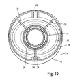
Fig. 8 . - Fig. 10
- is a cross-sectional view of the cap on the container of the second embodiment.
- Fig. 11
- is a schematic view of a third embodiment according to the present invention.
- Fig. 12
- is a perspective view of the container of the third embodiment without the cap.
- Fig. 13
- is a longitudinal sectional view of the dispenser of the third embodiment before the cap is correctly seated onto the container.
- Fig. 14
- is a longitudinal sectional view of the dispenser of the third embodiment after the cap is correctly seated onto the container.
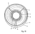
- Fig. 15
- is a cross-sectional view of the cap on the container of the third embodiment.
-
Fig. 1 shows a longitudinal sectional view of a first embodiment of the present invention. Particularly,Fig. 1 shows adispenser 10 suitable for storing cosmetic products. Thedispenser 10 comprises acontainer 12 and adispenser cap 14 configured to be seated onto thecontainer 12. Thecontainer 12 may be a bottle made of plastics and defines alongitudinal axis 16. Thecontainer 12 comprises at an upper end 18 a threadedneck 20 through which thelongitudinal axis 16 extends. - As shown in
Fig. 2 , which is a perspective view of the container without thecap 14, thecontainer 12 comprises aseat 22 at theupper end 18 on which thecap 14 may be seated, and awall portion 24, which may be cylindrical and may extend parallel with respect to thelongitudinal axis 16. Particularly, thewall portion 24 is coaxially arranged with respect to thelongitudinal axis 16 and thelongitudinal axis 16 may extend through a center of thewall portion 24. Theseat 22 is defined as a portion connecting theneck 20 and thewall portion 24. Theseat 22 has a continuously varying height in an axial direction defined by thelongitudinal axis 16 of thecontainer 12. Particularly, the axial height decreases such that only at a certain angle in an circumferential direction around thelongitudinal axis 16 the axial height is minimal and increases again towards other angles. Accordingly, theseat 22 may be formed similar to a inclined plane which is wound around thelongitudinal axis 16 in two directions and is inclined with respect to itself. The axial height is minimal at a radial outer position close to thewall portion 24. At this position, agroove 26 is provided. Thegroove 26 may be formed like a recess and may extend in a radial direction towards thelongitudinal axis 16. - As shown in
Fig. 3 , which is a longitudinal sectional view of thedispenser 10 before thecap 14 is correctly seated onto thecontainer 12 in its final position, thecap 14 comprises atop wall 28 and aside wall 30 protruding from thetop wall 28. At theside wall 30, a plurality ofwings 32 is provided which extend in a radial inner direction. For example, threewings 32 may be provided which may be evenly arranged in a circumferential direction. At least one of thewings 32 is longer in the direction of the longitudinal axis than the remainingwings 32. This specific wing may be called anextended wing 34 hereinafter. Theextended wing 34 extends to alower rim 36 of thecap 14, which is opposite to thetop wall 28, and flushes therewith. - As shown in
Fig. 3 , if thecap 14 is disposed on theseat 22 and theextended wing 34 engages a portion of theseat 22 having a greater axial height than the minimal axial height, thelower rim 36 and thecap 14 are spaced apart from thewall portion 24 of the container. As shown inFig. 4 , by means of rotating thecap 14, the cap may be seated onto theseat 22 in its final position. Particularly, due to the specific geometric formation of theseat 22 similar to a partly helical surface, an orientation for thecap 14 when axially positioning thecap 14 onto theseat 22 is provided. With an orientated guidance provided thereby, thecap 22 is automatically guided by axial contact of the cap'slower rim 36 and theseat 20 into one pre-defined position where theextended wing 34 is positioned in thegroove 26 even if thecap 14 is disposed in an inclined state with respect to thelongitudinal axis 16 of thedispenser 10. Accordingly, theseat 22 provides a guiding surface for thecap 14.Fig. 5 , which is a cross-sectional view perpendicular to thelongitudinal axis 16, shows thecap 14 with thewings 32 and theextended wing 34 engaging thegroove 26. Thus, thelower rim 36 and theseat 22 are not formed so as to have a thread which provides a guiding of thecap 14 for correctly orientating the same onto thecontainer 12 but due to the specific geometric formation of theseat 22, the cap is automatically guided into its final position when rotating thecap 14. This means, even if thecap 14 is positioned onto the upper end of theseat 22 in a tilted manner with respect to thelongitudinal axis 16 of thedispenser 10, thecap 14 will be correctly oriented when rotating in a circumferential direction around thelongitudinal axis 16 of thedispenser 10 and guided towards the final position. Particularly, thecap 14 may be rotated in two circumferential directions, i.e. clockwise and counter-clockwise. Thereby, thecap 14 slides with theextended wing 34 on the guide surface of theseat 22. During rotating thecap 14 on theseat 22, thecap 14 approaches theseat 22 depending on the rotation angle and rotation position, respectively. Accordingly, thecap 14 may be moved from a tilted orientation into an axially aligned orientation during rotating thecap 14 on theseat 22 by means of the guiding surfaces provided by the specific design of theseat 22 and theextended wing 24 of thecap 14 which cooperate. -
Fig. 6 shows a longitudinal sectional view of a second embodiment of the present invention, wherein only the differences from the first embodiment will be described and same constructional members are provided with the same reference numerals. According to the second embodiment, theseat 22 and is oval if seen in an axial direction of thelongitudinal axis 16. As can be best seen inFig. 7 , which is a perspective view of thecontainer 12 without thecap 14, an axial height of theseat 22 continuously varies along different angles in the circumferential direction around thelongitudinal axis 16 of thedispenser 10, thereby providing an orientation for thecap 14. The course of the axial height of theseat 22 as a function of the angle is continuously varying and comprises two minima and two maxima leading to two symmetric engaging positions, which may be defined at 0° and 180° in a circumferential direction around thelongitudinal axis 16 of thedispenser 10 by means of twogrooves 26. Thecap 14 may be the same as explained with respect to the first embodiment. With the oriented guidance provided by the specific geometric shape of theseat 22 and theextended wing 34, even if thecap 14 is not correctly positioned on the seat as shown inFig. 8 , thecap 14 is automatically guided towards one of thegrooves 26 of theseat 22 as shown inFig. 9 .Fig. 10 , which is a cross-sectional view perpendicular to thelongitudinal axis 16, clearly shows how theextended wing 34 engages one of thegrooves 26. Particularly, thecap 14 may be rotated in two circumferential directions, i.e. clockwise and counter-clockwise. -
Fig. 11 shows a longitudinal sectional view of a third embodiment of the present invention, wherein only the differences from the first embodiment will be described and the same constructional members are provided with the same reference numerals. According to the third embodiment, theseat 22 comprises a radial surface area having an axial height in a direction of thelongitudinal axis 16 of thedispenser 10, which follows a helix around thelongitudinal axis 16 of thedispenser 10 As can be best seen inFig. 12 , which is a perspective view of thecontainer 12 without thecap 14. This provides a guidance in form of a radial surface which may be similar to an inclined plane and provides an angular orientation for thecap 14. With the oriented guidance provided by this specific surface shape, even if thecap 14 is not correctly seated on theseat 22 as shown inFig. 13 , thecap 14 is automatically guided towards one defined position when rotated around thelongitudinal axis 16 of thedispenser 10 as shown inFig. 14 , which may be defined at the end of the helical surface of theseat 22 closest to thewall portion 24 of thecontainer 12. Particularly, thegroove 26 of the third embodiment may be smaller than thegroove 26 of the first embodiment because the helical guiding surface of theseat 22 includes anabutment surface 38 extending in an upright direction from an radial outer portion of theseat 22 close to thewall portion 24 and adjacent thegroove 26.Fig. 15 , which is a cross-sectional view perpendicular to thelongitudinal axis 16, clearly shows how theextended wing 34 engages thegroove 26. In this embodiment, thecap 14 may be rotated only in one circumferential direction, i.e. counter-clockwise in the view ofFig. 12 . - All three embodiments as explained above have in common that the
cap 14 and theseat 22 are formed such that guiding surfaces thereof allow to move thecap 14 to a certain position where thecap 14 is correctly oriented onto thecontainer 12 without the necessity of a provision of an abutment or stopper surface. i.e. thecap 14 may be moved to its final position which is not defined by an additional constructional member. Particularly, the guiding function may be supported by anextended wing 34 of thecap 14. The three embodiments differ in the number of allowable rotation directions for thecap 14 and the number of defined final positions for thecap 14. Further, due to the geometric formation of the surfaces of theseat 22, thecap 14 is not only correctly guided in the rotational direction but also in the axial direction, i.e. a deviation from thelongitudinal axis 16 at the final position is not possible even if thecap 14 is disposed inclined with respect to theseat 22 at the beginning of rotating the same. Thecap 14 may be positioned onto theseat 22 in a gas tight and/or liquid tight manner. Fur this purpose, thecap 14 may additionally comprise an inner skirt having a thread corresponding to the thread of theneck 20 of thecontainer 12. - The dispenser according to the invention can be used to store liquid, particularly volatile liquid, gel or powdered products of any description but is more desirably employed for cosmetics, toiletries and other household products. Examples of such products are perfume, eau de toilette, talcum powder, shower gel, foam bath product, shampoo, make-up products, sunscreen products, suntan products and dishwashing liquid.
- The dimensions and values disclosed herein are not to be understood as being strictly limited to the exact numerical values recited. Instead, unless otherwise specified, each such dimension is intended to mean both the recited value and a functionally equivalent range surrounding that value. For example, a dimension disclosed as "40 mm" is intended to mean "about 40 mm."
Claims (8)
- Dispenser (10) for dispensing a cosmetic product, comprising a container (12) defining a longitudinal axis (16), a cap (14) configured to be disposed on the container (12), a seat (22) provided at the container (12), wherein the seat (22) is shaped so as to have a surface with a continuously varying axial height in a circumferential direction around the longitudinal axis (16).
- Dispenser (10) for dispensing a cosmetic product of claim 1, wherein at a certain angle in an circumferential direction around the longitudinal axis (16) the axial height is minimal and increases again towards other angles.
- Dispenser (10) for dispensing a cosmetic product of claim 1, wherein an axial height of the seat (22) continuously varies along different angles in a circumferential direction around the longitudinal axis (16) of the dispenser (10) and comprises two minima and two maxima leading to two symmetric engaging positions.
- Dispenser (10) for dispensing a cosmetic product of claim 3, wherein the minima and the maxima of the axial height are defined at opposite positions in a circumferential direction around the longitudinal axis (16) of the dispenser (10).
- Dispenser (10) for dispensing a cosmetic product of claim 1, wherein the seat (22) comprises a radial surface area having an axial height in a direction of the longitudinal axis (16) of the dispenser (10) which follows a helix around the longitudinal axis (16) of the dispenser (10).
- Dispenser (10) for dispensing a cosmetic product of claim 1, wherein the surface of the seat (22) comprises at least one groove (26) positioned close to a wall portion (24) of the container (12).
- Dispenser (10) for dispensing a cosmetic product of claim 6, wherein the cap (14) comprises a wing (34) adapted to engage the at least one groove (26).
- Dispenser (10) for dispensing a cosmetic product of claim 7, wherein the cap (14) comprises a plurality of wings (32, 34), wherein one of the wings (34) is longer in the direction of the longitudinal axis (16) than the remaining wings (32) and adapted to engage the at least one groove (26).
Priority Applications (1)
| Application Number | Priority Date | Filing Date | Title |
|---|---|---|---|
| EP14163362.8A EP2927150A1 (en) | 2014-04-03 | 2014-04-03 | Dispensing cap allignment |
Applications Claiming Priority (1)
| Application Number | Priority Date | Filing Date | Title |
|---|---|---|---|
| EP14163362.8A EP2927150A1 (en) | 2014-04-03 | 2014-04-03 | Dispensing cap allignment |
Publications (1)
| Publication Number | Publication Date |
|---|---|
| EP2927150A1 true EP2927150A1 (en) | 2015-10-07 |
Family
ID=50440512
Family Applications (1)
| Application Number | Title | Priority Date | Filing Date |
|---|---|---|---|
| EP14163362.8A Withdrawn EP2927150A1 (en) | 2014-04-03 | 2014-04-03 | Dispensing cap allignment |
Country Status (1)
| Country | Link |
|---|---|
| EP (1) | EP2927150A1 (en) |
Citations (6)
| Publication number | Priority date | Publication date | Assignee | Title |
|---|---|---|---|---|
| US4093096A (en) | 1977-05-19 | 1978-06-06 | Societe Anonyme Dite: Arts Et Techniques Nouvelles | Removable stopper for a screw-neck bottle |
| US4117945A (en) * | 1977-06-29 | 1978-10-03 | Owens-Illinois, Inc. | Child-resistant safety closure |
| US4213534A (en) * | 1979-06-28 | 1980-07-22 | Sunbeam Plastics Corporation | Child-resistant closure |
| EP0117722A2 (en) | 1983-02-25 | 1984-09-05 | Unilever Plc | Container having a screw-on closure |
| US20040140329A1 (en) * | 2003-01-21 | 2004-07-22 | Unilever Home & Personal Care Usa, | Ovaloid bottle with overcap |
| US20040222181A1 (en) * | 2003-05-09 | 2004-11-11 | Drug Plastics & Glass Company, Inc. | Container and child-resistant closure system |
-
2014
- 2014-04-03 EP EP14163362.8A patent/EP2927150A1/en not_active Withdrawn
Patent Citations (6)
| Publication number | Priority date | Publication date | Assignee | Title |
|---|---|---|---|---|
| US4093096A (en) | 1977-05-19 | 1978-06-06 | Societe Anonyme Dite: Arts Et Techniques Nouvelles | Removable stopper for a screw-neck bottle |
| US4117945A (en) * | 1977-06-29 | 1978-10-03 | Owens-Illinois, Inc. | Child-resistant safety closure |
| US4213534A (en) * | 1979-06-28 | 1980-07-22 | Sunbeam Plastics Corporation | Child-resistant closure |
| EP0117722A2 (en) | 1983-02-25 | 1984-09-05 | Unilever Plc | Container having a screw-on closure |
| US20040140329A1 (en) * | 2003-01-21 | 2004-07-22 | Unilever Home & Personal Care Usa, | Ovaloid bottle with overcap |
| US20040222181A1 (en) * | 2003-05-09 | 2004-11-11 | Drug Plastics & Glass Company, Inc. | Container and child-resistant closure system |
Similar Documents
| Publication | Publication Date | Title |
|---|---|---|
| CA2874543C (en) | Container having a cover | |
| US20070205233A1 (en) | Dispenser for creamy products, comprising an axially sunk cap | |
| US7959022B2 (en) | Container with a polygonal neck | |
| CA2573385C (en) | Attachment means for a cosmetic dispenser | |
| JP6880226B2 (en) | Closing caps for devices for packaging products, especially cosmetics | |
| US4271974A (en) | Bottle with prealigned closure | |
| US7674061B2 (en) | Fluid cosmetic dispenser | |
| US20180104463A1 (en) | Roll-on dispenser for medicamets | |
| JP2017537856A (en) | Children's misuse closure for containers | |
| ES2974762T3 (en) | Refillable conditioning set for cosmetic product | |
| EP3570701B1 (en) | Hair applicator | |
| US20170065800A1 (en) | Roll-on dispenser for medicaments | |
| US10994986B2 (en) | Dispenser | |
| JP2022011627A (en) | Delivery container | |
| CN105916778B (en) | Distribution capping and the container covered with such distribution | |
| US11981478B2 (en) | Container | |
| RU2707693C2 (en) | Method of applying cap to container and device for applying cap to container | |
| US11377272B2 (en) | Device for closing a container by screwing, secured by a retractable lug | |
| US3283966A (en) | Liquid dispenser and closure for bottles | |
| EP3601082B1 (en) | Closure cap for packaging a cosmetic product | |
| EP2714536B1 (en) | A closure | |
| JP6802751B2 (en) | Exterior container for refill container and coating container using this | |
| JP7309273B2 (en) | Feeding container | |
| EP2739545A1 (en) | Flow regulating dispensing closure | |
| US20140166678A1 (en) | Device for assembly by elastic interlocking |
Legal Events
| Date | Code | Title | Description |
|---|---|---|---|
| PUAI | Public reference made under article 153(3) epc to a published international application that has entered the european phase |
Free format text: ORIGINAL CODE: 0009012 |
|
| AK | Designated contracting states |
Kind code of ref document: A1 Designated state(s): AL AT BE BG CH CY CZ DE DK EE ES FI FR GB GR HR HU IE IS IT LI LT LU LV MC MK MT NL NO PL PT RO RS SE SI SK SM TR |
|
| AX | Request for extension of the european patent |
Extension state: BA ME |
|
| 17P | Request for examination filed |
Effective date: 20160203 |
|
| 17Q | First examination report despatched |
Effective date: 20160531 |
|
| STAA | Information on the status of an ep patent application or granted ep patent |
Free format text: STATUS: EXAMINATION IS IN PROGRESS |
|
| RAP1 | Party data changed (applicant data changed or rights of an application transferred) |
Owner name: NOXELL CORPORATION |
|
| GRAP | Despatch of communication of intention to grant a patent |
Free format text: ORIGINAL CODE: EPIDOSNIGR1 |
|
| STAA | Information on the status of an ep patent application or granted ep patent |
Free format text: STATUS: GRANT OF PATENT IS INTENDED |
|
| RIC1 | Information provided on ipc code assigned before grant |
Ipc: B65D 41/04 20060101AFI20170508BHEP |
|
| INTG | Intention to grant announced |
Effective date: 20170523 |
|
| STAA | Information on the status of an ep patent application or granted ep patent |
Free format text: STATUS: THE APPLICATION IS DEEMED TO BE WITHDRAWN |
|
| 18D | Application deemed to be withdrawn |
Effective date: 20171003 |