EP0117722A2 - Container having a screw-on closure - Google Patents
Container having a screw-on closure Download PDFInfo
- Publication number
- EP0117722A2 EP0117722A2 EP84301165A EP84301165A EP0117722A2 EP 0117722 A2 EP0117722 A2 EP 0117722A2 EP 84301165 A EP84301165 A EP 84301165A EP 84301165 A EP84301165 A EP 84301165A EP 0117722 A2 EP0117722 A2 EP 0117722A2
- Authority
- EP
- European Patent Office
- Prior art keywords
- container
- closure
- inner skirt
- outer cap
- skirt
- Prior art date
- Legal status (The legal status is an assumption and is not a legal conclusion. Google has not performed a legal analysis and makes no representation as to the accuracy of the status listed.)
- Withdrawn
Links
Images

Classifications
-
- B—PERFORMING OPERATIONS; TRANSPORTING
- B65—CONVEYING; PACKING; STORING; HANDLING THIN OR FILAMENTARY MATERIAL
- B65D—CONTAINERS FOR STORAGE OR TRANSPORT OF ARTICLES OR MATERIALS, e.g. BAGS, BARRELS, BOTTLES, BOXES, CANS, CARTONS, CRATES, DRUMS, JARS, TANKS, HOPPERS, FORWARDING CONTAINERS; ACCESSORIES, CLOSURES, OR FITTINGS THEREFOR; PACKAGING ELEMENTS; PACKAGES
- B65D51/00—Closures not otherwise provided for
- B65D51/18—Arrangements of closures with protective outer cap-like covers or of two or more co-operating closures
-
- B—PERFORMING OPERATIONS; TRANSPORTING
- B65—CONVEYING; PACKING; STORING; HANDLING THIN OR FILAMENTARY MATERIAL
- B65D—CONTAINERS FOR STORAGE OR TRANSPORT OF ARTICLES OR MATERIALS, e.g. BAGS, BARRELS, BOTTLES, BOXES, CANS, CARTONS, CRATES, DRUMS, JARS, TANKS, HOPPERS, FORWARDING CONTAINERS; ACCESSORIES, CLOSURES, OR FITTINGS THEREFOR; PACKAGING ELEMENTS; PACKAGES
- B65D41/00—Caps, e.g. crown caps or crown seals, i.e. members having parts arranged for engagement with the external periphery of a neck or wall defining a pouring opening or discharge aperture; Protective cap-like covers for closure members, e.g. decorative covers of metal foil or paper
- B65D41/02—Caps or cap-like covers without lines of weakness, tearing strips, tags, or like opening or removal devices
- B65D41/04—Threaded or like caps or cap-like covers secured by rotation
- B65D41/0492—Threaded or like caps or cap-like covers secured by rotation formed by several elements connected together
-
- B—PERFORMING OPERATIONS; TRANSPORTING
- B65—CONVEYING; PACKING; STORING; HANDLING THIN OR FILAMENTARY MATERIAL
- B65D—CONTAINERS FOR STORAGE OR TRANSPORT OF ARTICLES OR MATERIALS, e.g. BAGS, BARRELS, BOTTLES, BOXES, CANS, CARTONS, CRATES, DRUMS, JARS, TANKS, HOPPERS, FORWARDING CONTAINERS; ACCESSORIES, CLOSURES, OR FITTINGS THEREFOR; PACKAGING ELEMENTS; PACKAGES
- B65D2251/00—Details relating to container closures
- B65D2251/0003—Two or more closures
- B65D2251/0006—Upper closure
- B65D2251/0015—Upper closure of the 41-type
-
- B—PERFORMING OPERATIONS; TRANSPORTING
- B65—CONVEYING; PACKING; STORING; HANDLING THIN OR FILAMENTARY MATERIAL
- B65D—CONTAINERS FOR STORAGE OR TRANSPORT OF ARTICLES OR MATERIALS, e.g. BAGS, BARRELS, BOTTLES, BOXES, CANS, CARTONS, CRATES, DRUMS, JARS, TANKS, HOPPERS, FORWARDING CONTAINERS; ACCESSORIES, CLOSURES, OR FITTINGS THEREFOR; PACKAGING ELEMENTS; PACKAGES
- B65D2251/00—Details relating to container closures
- B65D2251/0003—Two or more closures
- B65D2251/0068—Lower closure
- B65D2251/0078—Lower closure of the 41-type
Definitions
- the invention relates to a container, particularly a bottle for perfume or the like, having a screw on closure, in which when viewed externally from above, both the body of the container and the closure are non-circular in outline.
- Such containers which are especially intended for liquids, are almost invariably provided with a deformable ring seal or similar sealing means, but because manufacturing tolerances are such that an exact conformity cannot usually be obtained between the thread of the container and that of the closure, it is frequently the case that the closure does not occupy its desired orientation relative to the container when in a fully closed position. This is unsatisfactory both from . an aesthetic point of view, and in relation to bulk packaging and transportation, since a closure skew fitted to the container can present projecting edges which are an obstacle to close packaging and can cause the closure not to be fully closed, thereby resulting in possible spillage or evaporation of the liquid during transportation or storage prior to sale.
- both the inner and the outer closure elements are constructed of relatively rigid materials, which can be the same or different materials, so that relative rotation between the closure elements is not possible, then a-more satisfactory closure results which can be repeatedly screwed onto and unscrewed from a container without this problem of wear between the closure elements, while ensuring, by the provision of a suitable stop, that desired orientation of the closure on the container is always obtainable when the container is closed and sealed.
- a container having at its upper end a screw threaded neck adapted to receive a screw threaded closure comprising an inner skirt and an outer cap axially engaged with the inner skirt, the container having an abutment adapted to be contacted by a stop on the closure so as to orientate the closure in the closed position with respect to the container, characterised in that the outer cap is engaged non-rotatably with the inner skirt; and the inner skirt is provided with sealing means to close the neck of the container, and form a vapour-tight seal therewith over an angle of relative rotation of the skirt and the container of at least 45°.
- the container has a threaded portion, such as a neck, onto which the closure is adapted to be screwed.
- a threaded portion such as a neck
- An example of such a container is a bottle for perfume or the like, having a neck portion which is threaded externally to receive a screw-on closure.
- the container also has at least one abutment for contact with the closure when the closure is orientated relative to the container in the desired position and the container is sealed.
- This abutment on the container can present an axially- or near-axially orientated surface for co-operation with the closure, or it can alternatively present a radially- or near-radially orientated surface for contact with the closure.
- the abutment is carried below the screw thread of the neck of the container.
- the inner skirt of the closure is threaded internally and is adapted to be screwed onto the correspondingly threaded portion, such as a neck, of the container, in such a manner as to effect a vapour-tight seal to prevent spillage or evaporation of the container contents.
- a vapour tight seal is obtained when screwing the inner skirt onto the container in a closing direction when rotation of the inner skirt reaches an angle of rotation of not less than 45° from the position where the closure is fully orientated in the container.
- sealing can be achieved at an angle of relative rotation between the skirt and the container of at least 60°, and preferably at least 90° from this fully orientated position.
- the inner skirt can be provided with a relatively pliable or flexible insert or portion whose deformation makes sealing contact with the container, such as at the top of or within the neck of the container.
- Vapour tight sealing of the inner skirt on the container in this manner at a position before the inner skirt is fully tightened onto the threaded portion of the container is desirable in order to allow for final adjustment of the closure after the outer cap has been fitted to the inner skirt, in order to achieve correct orientation of the closure with respect to the container at the position where the closure comes into contact with the abutment on the container.
- the inner skirt is also provided externally with means for receiving and non-rotatably engaging with the outer cap.
- this external engagement means comprises axially arranged ribs and/or grooves carried on the external surface of the inner skirt.
- the external surface of the inner skirt is also preferably frustoconical such that it tapers slightly inwards towards its upper end.
- the external diameter of the upper end of the skirt can . thus be slightly smaller than the corresponding internal diameter of the outer cap, to facilitate fitting of the outer cap onto the inner skirt during assembly.
- the preferred frustoconical external surface of the inner skirt also provides for a more positive engagement of inner skirt and outer cap to ensure that the two closure elements are not readily separable in use, for example if the container is picked up by gripping the outer cap, and further to ensure that relative rotation of the two elements after assembly is not possible.
- the frustoconical external surface of the inner skirt tapers inwards from its base to its top at an angle to the vertical which is slightly greater than the corresponding taper angle of the inner wall of the outer cap.
- the taper angles of the walls of the inner skirt and the outer cap can be 0° 15' and-O o 10' respectively.
- the lower rim of the inner skirt can form a stop having a radial surface for contacting the abutment on the container which preferably presents a corresponding radial surface against which the inner skirt can be screwed, in order to orientate correctly the closure on the container.
- the outer cap of the closure is provided internally with means for engagement with the inner skirt.
- this internal engagement means comprises ribs and/or grooves carried on the internal axial surface of the outer cap, which itself can also be slightly tapered to provide a frustoconical surface to facilitate engagement with the inner skirt.
- the outer cap can be provided with a stop for contacting the abutment on the container which can present an axial surface against which the outer cap stop can be screwed, as an alternative means for orientating correctly the closure on the container.
- the invention also provides a method of fitting a closure to a container of the type hereinbefore described which comprises the steps of screwing the inner skirt onto the threaded neck of the container so as to achieve a vapour-tight seal; fitting the outer cap over the inner skirt thereby to engage the ribs and/or corresponding grooves of the inner skirt and outer cap, such that the outer cap cannot be rotated relative to the inner skirt; and, if necessary, screwing the assembled closure further onto the threaded neck of the container so as to bring the stop into contact with the abutment.
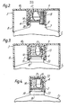
- a bottle 1 is provided with a 2-part closure 2 consisting of an outer cap 3 and an inner skirt 4.
- the bottle 1 the body of which is non-circular in plan view, has an externally threaded neck portion 5 adapted to receive the closure 2.
- Below the thread on the neck 5 is a centering ring 6 and at one side of the neck on the shoulder of the bottle is a single abutment 7 presenting an axially- or near-axially orientated surface for contact with the closure 2.
- the outer cap 3 of the closure 2 has an outer side-wall 8 which is also non-circular in plan view, and an inner annular side-wall 9 depending from a top-wall 10.
- the inner surface of the inner side-wall 9 carries alternate vertical ribs and grooves 11.
- the lower edge of the inner side-wall 9 at one side carries a stop 12.
- the inner skirt 4 has an annular side-wall 13 which is internally threaded at 14 and externally has alternating axially orientated ribs and grooves.15.
- a top wall 16 of the inner skirt 4 carries an annular deformable sealing flange 17, adapted to enter the neck 5 of the bottle 1 when the closure is screwed in place, the material and dimensions of the sealing flange 17 being such that a vapour-tight seal is obtained throughout an angle of about 60° of relative rotation of the skirt and the bottle.
- the bottle When assembling the bottle 1 and closure 2, as shown in Figures 1 and 2, the bottle is first filled with perfume, Eau de Toilette, or the like, and the inner skirt 4 is screwed onto the threaded neck 5 of the bottle until the sealing flange 17 forms a vapour tight seal with the bottle, at which point the annular sealing flange 17 will have entered the neck of the bottle, thus effecting a vapour-tight seal at an angle of relative rotation of about 60° from a fully tightened position.
- the flexibility and dimensions of this flange 17 are such as to maintain a vapour-tight seal on the bottle before the inner skirt 4 is fully tightened during the final orientating sequence.
- the outer cap 3 is then placed over the inner skirt 4, so that the stop engages the abutment on the bottle.
- any slight wear or deformation of the threaded portions will not effect the vapour-tight function of the closure in view of the ability of the annular sealing flange 17 to seal the contents of the bottle in a vapour-tight manner from an angle of relative rotation of the skirt and the bottle of at least 45° from the fully closed and fully orientated position.
- the closure 2 in Figure 3 is substantially similar to that shown in Figures 1 and 2, except that the outer cap 3 has no stop, and the lower edge 20 of the inner skirt functions as a stop for contact with the surface 19.
- the inner skirt 4 is first screwed onto the neck 5 of the bottle 1 until the lower edge 20 of the inner skirt 4 contacts the surface 19 of the abutment 18.
- the outer cap 3 is then placed over the inner skirt 4 in the manner described earlier in the desired configuration relative to the bottle without further need for orientation.
- the construction of the inner skirt 4 is similar to that shown in Figures 1,2 and 3 except that the integral annular sealing flange 17 is replaced by a seal insert 21 having an annular flange 22 of relatively flexible material as compared with the relatively rigid material from which the inner skirt is constructed.
- the seal insert 21 forms a push fit within the inner skirt 4 and the annular flange 22 is adapted to form a vapour tight seal with open neck 5 of the bottle 1 when the inner skirt 4 (or the assembled closure 2) is screwed on the bottle neck, the seal being obtained at an angle of relative rotation of the skirt and the bottle of at least 45° from the fully closed and fully orientated position.
- the container and closure according to the invention can be used to store liquid, particularly volatile liquid, gel or powdered products of any description but is more desirably employed for cosmetics, toiletries and other household products.
- liquid, particularly volatile liquid, gel or powdered products of any description but is more desirably employed for cosmetics, toiletries and other household products.
- examples of such products are perfume, eau de toilette, talcum powder, shower gel, foam bath product, shampoo, make-up products, sunscreen products, suntan products and dishwashing liquid.
Landscapes
- Engineering & Computer Science (AREA)
- Mechanical Engineering (AREA)
- Closures For Containers (AREA)
Abstract
Description
- The invention relates to a container, particularly a bottle for perfume or the like, having a screw on closure, in which when viewed externally from above, both the body of the container and the closure are non-circular in outline.
- It is generally recognised that when a container whose body is non-circular in plan view is fitted with a screw-on closure which is also non-circular in plan view, the closure should always line up with, or otherwise always adopt a desired orientation with respect to the container when fully closed, even after repeated removal of the closure and replacement of it on the container.
- Such containers, which are especially intended for liquids, are almost invariably provided with a deformable ring seal or similar sealing means, but because manufacturing tolerances are such that an exact conformity cannot usually be obtained between the thread of the container and that of the closure, it is frequently the case that the closure does not occupy its desired orientation relative to the container when in a fully closed position. This is unsatisfactory both from . an aesthetic point of view, and in relation to bulk packaging and transportation, since a closure skew fitted to the container can present projecting edges which are an obstacle to close packaging and can cause the closure not to be fully closed, thereby resulting in possible spillage or evaporation of the liquid during transportation or storage prior to sale.
- It is with the provision of a container and a closure which are both non-circular in plan view, and which do not have the aforesaid disadvantages while always permitting precise alignment or orientation of the closure relative to the container when the closure is screwed on to the fully closed position, that this invention is concerned.
- It has been proposed in French patent 78 20257 to provide a device for positioning a cap on a bottle, the cap consisting of a rigid body on the interior of which is mounted a relatively pliable skirt, the skirt having an internal thread for screwing onto the external neck of the bottle, the neck of the bottle having at least one vertical radial surface forming an abutment against which is brought a stop incorporated in the cap on the lower part of the internal surface of the rigid body portion when the bottle is closed. It is an essential feature of the cap described in that patent that the outer body portion can be rotated relative to the inner skirt in order to enable the cap finally to be correctly positioned on the bottle. This relative rotation is facilitated by the relatively pliable nature of the material from which the skirt is constructed, so that the means by which the two cap elements engage with each other, for example external ribs on the skirt and internal grooves on the body portion, can be overridden by deformation of the relatively pliable skirt.
- When constructing a screw-on closure for a container in which the externally ribbed inner skirt of the closure is of relatively pliable material, such as polyethylene, and the internally grooved outer portion is of relatively rigid material, such as polystyrene, it is apparent that wear of the ribbed and grooved surfaces can occur such that when attempting to remove the closure after tightening it on the container, the outer portion can rotate around the inner skirt without unscrewing the skirt from the container. This presents obvious problems for the consumer when attempting to remove the closure from the container. We have, however, now discovered that when both the inner and the outer closure elements are constructed of relatively rigid materials, which can be the same or different materials, so that relative rotation between the closure elements is not possible, then a-more satisfactory closure results which can be repeatedly screwed onto and unscrewed from a container without this problem of wear between the closure elements, while ensuring, by the provision of a suitable stop, that desired orientation of the closure on the container is always obtainable when the container is closed and sealed.
- According to the invention there is provided a container having at its upper end a screw threaded neck adapted to receive a screw threaded closure comprising an inner skirt and an outer cap axially engaged with the inner skirt, the container having an abutment adapted to be contacted by a stop on the closure so as to orientate the closure in the closed position with respect to the container,
characterised in that
the outer cap is engaged non-rotatably with the inner skirt; and
the inner skirt is provided with sealing means to close the neck of the container, and form a vapour-tight seal therewith over an angle of relative rotation of the skirt and the container of at least 45°. - The container has a threaded portion, such as a neck, onto which the closure is adapted to be screwed. An example of such a container is a bottle for perfume or the like, having a neck portion which is threaded externally to receive a screw-on closure.
- The container also has at least one abutment for contact with the closure when the closure is orientated relative to the container in the desired position and the container is sealed. This abutment on the container can present an axially- or near-axially orientated surface for co-operation with the closure, or it can alternatively present a radially- or near-radially orientated surface for contact with the closure. Preferably, the abutment is carried below the screw thread of the neck of the container.
- The inner skirt of the closure is threaded internally and is adapted to be screwed onto the correspondingly threaded portion, such as a neck, of the container, in such a manner as to effect a vapour-tight seal to prevent spillage or evaporation of the container contents.
- It is a feature of the inner skirt that a vapour tight seal is obtained when screwing the inner skirt onto the container in a closing direction when rotation of the inner skirt reaches an angle of rotation of not less than 45° from the position where the closure is fully orientated in the container. Usually, sealing can be achieved at an angle of relative rotation between the skirt and the container of at least 60°, and preferably at least 90° from this fully orientated position.
- In order to obtain an adequate vapour tight seal, the inner skirt can be provided with a relatively pliable or flexible insert or portion whose deformation makes sealing contact with the container, such as at the top of or within the neck of the container.
- Vapour tight sealing of the inner skirt on the container in this manner at a position before the inner skirt is fully tightened onto the threaded portion of the container is desirable in order to allow for final adjustment of the closure after the outer cap has been fitted to the inner skirt, in order to achieve correct orientation of the closure with respect to the container at the position where the closure comes into contact with the abutment on the container.
- The inner skirt is also provided externally with means for receiving and non-rotatably engaging with the outer cap. Preferably, this external engagement means comprises axially arranged ribs and/or grooves carried on the external surface of the inner skirt. The external surface of the inner skirt is also preferably frustoconical such that it tapers slightly inwards towards its upper end. The external diameter of the upper end of the skirt can . thus be slightly smaller than the corresponding internal diameter of the outer cap, to facilitate fitting of the outer cap onto the inner skirt during assembly. The preferred frustoconical external surface of the inner skirt also provides for a more positive engagement of inner skirt and outer cap to ensure that the two closure elements are not readily separable in use, for example if the container is picked up by gripping the outer cap, and further to ensure that relative rotation of the two elements after assembly is not possible.
- According to a preferred embodiment of the invention, the frustoconical external surface of the inner skirt tapers inwards from its base to its top at an angle to the vertical which is slightly greater than the corresponding taper angle of the inner wall of the outer cap. By way of example, the taper angles of the walls of the inner skirt and the outer cap can be 0° 15' and-Oo 10' respectively.
- The lower rim of the inner skirt can form a stop having a radial surface for contacting the abutment on the container which preferably presents a corresponding radial surface against which the inner skirt can be screwed, in order to orientate correctly the closure on the container.
- The outer cap of the closure is provided internally with means for engagement with the inner skirt. Preferably, this internal engagement means comprises ribs and/or grooves carried on the internal axial surface of the outer cap, which itself can also be slightly tapered to provide a frustoconical surface to facilitate engagement with the inner skirt.
- The outer cap can be provided with a stop for contacting the abutment on the container which can present an axial surface against which the outer cap stop can be screwed, as an alternative means for orientating correctly the closure on the container.
- The invention also provides a method of fitting a closure to a container of the type hereinbefore described which comprises the steps of screwing the inner skirt onto the threaded neck of the container so as to achieve a vapour-tight seal; fitting the outer cap over the inner skirt thereby to engage the ribs and/or corresponding grooves of the inner skirt and outer cap, such that the outer cap cannot be rotated relative to the inner skirt; and, if necessary, screwing the assembled closure further onto the threaded neck of the container so as to bring the stop into contact with the abutment.
- The invention is illustrated and further particularly described with reference to the accompanying drawings in which:
- Figure 1 is a part-sectional elevation of the screw-on closure of the invention used in connection with a perfume bottle, showing the closure elements separated from each other and from the bottle;
- Figure 2 is a part-sectional elevation of the screw-on closure and bottle shown in figure 1, but with the closure fitted to the bottle;
- Figure 3 is also a part-sectional elevation of a screw-on closure fitted to a bottle similar to that shown in Figures 2, but with alternative stop and abutment for orientation of the closure on the bottle.
- Figure 4 is a part-sectional elevation of the inner skirt portion of a screw-on closure similar to that shown in Figure 3 fitted to a bottle, the inner skirt showing an alternative means for sealing the bottle.
- In Figures 1 and 2, a bottle 1 is provided with a 2-
part closure 2 consisting of anouter cap 3 and aninner skirt 4. The bottle 1, the body of which is non-circular in plan view, has an externally threadedneck portion 5 adapted to receive theclosure 2. Below the thread on theneck 5 is a centering ring 6 and at one side of the neck on the shoulder of the bottle is asingle abutment 7 presenting an axially- or near-axially orientated surface for contact with theclosure 2. - The
outer cap 3 of theclosure 2 has an outer side-wall 8 which is also non-circular in plan view, and an inner annular side-wall 9 depending from a top-wall 10. The inner surface of the inner side-wall 9 carries alternate vertical ribs andgrooves 11. The lower edge of the inner side-wall 9 at one side carries astop 12. - The
inner skirt 4 has an annular side-wall 13 which is internally threaded at 14 and externally has alternating axially orientated ribs and grooves.15. Atop wall 16 of theinner skirt 4 carries an annulardeformable sealing flange 17, adapted to enter theneck 5 of the bottle 1 when the closure is screwed in place, the material and dimensions of the sealingflange 17 being such that a vapour-tight seal is obtained throughout an angle of about 60° of relative rotation of the skirt and the bottle. - When assembling the bottle 1 and
closure 2, as shown in Figures 1 and 2, the bottle is first filled with perfume, Eau de Toilette, or the like, and theinner skirt 4 is screwed onto the threadedneck 5 of the bottle until the sealingflange 17 forms a vapour tight seal with the bottle, at which point theannular sealing flange 17 will have entered the neck of the bottle, thus effecting a vapour-tight seal at an angle of relative rotation of about 60° from a fully tightened position. The flexibility and dimensions of thisflange 17 are such as to maintain a vapour-tight seal on the bottle before theinner skirt 4 is fully tightened during the final orientating sequence. - The
outer cap 3 is then placed over theinner skirt 4, so that the stop engages the abutment on the bottle. - After successive use by the consumer who will unscrew and replace the closure on the bottle, any slight wear or deformation of the threaded portions, such as might result in an apparently slightly loose fit, will not effect the vapour-tight function of the closure in view of the ability of the
annular sealing flange 17 to seal the contents of the bottle in a vapour-tight manner from an angle of relative rotation of the skirt and the bottle of at least 45° from the fully closed and fully orientated position. - The inability of the outer cap to rotate relative to the inner skirt after assembly of the closure will ensure that the outer cap does not itself rotate relative to the inner skirt when unscrewing the closure, thus always ensuring that the inner cap effects a vapour-tight seal on the bottle when replacing the closure after dispensing contents from the bottle.
- In Figure 3, the construction of the bottle 1 is similar to that shown in Figures 1 and 2, except that the
single abutment 7 is replaced by anannular abutment 18 presenting an annularhorizontal surface 19. - The
closure 2 in Figure 3 is substantially similar to that shown in Figures 1 and 2, except that theouter cap 3 has no stop, and thelower edge 20 of the inner skirt functions as a stop for contact with thesurface 19. - When assembling the bottle and closure of the type shown in Figure 3, the
inner skirt 4 is first screwed onto theneck 5 of the bottle 1 until thelower edge 20 of theinner skirt 4 contacts thesurface 19 of theabutment 18. - The
outer cap 3 is then placed over theinner skirt 4 in the manner described earlier in the desired configuration relative to the bottle without further need for orientation. - In Figure 4, the construction of the
inner skirt 4 is similar to that shown in Figures 1,2 and 3 except that the integralannular sealing flange 17 is replaced by a seal insert 21 having anannular flange 22 of relatively flexible material as compared with the relatively rigid material from which the inner skirt is constructed. The seal insert 21 forms a push fit within theinner skirt 4 and theannular flange 22 is adapted to form a vapour tight seal withopen neck 5 of the bottle 1 when the inner skirt 4 (or the assembled closure 2) is screwed on the bottle neck, the seal being obtained at an angle of relative rotation of the skirt and the bottle of at least 45° from the fully closed and fully orientated position. - The container and closure according to the invention can be used to store liquid, particularly volatile liquid, gel or powdered products of any description but is more desirably employed for cosmetics, toiletries and other household products. Examples of such products are perfume, eau de toilette, talcum powder, shower gel, foam bath product, shampoo, make-up products, sunscreen products, suntan products and dishwashing liquid.
Claims (11)
characterised in that
the outer cap is engaged non-rotatably with the inner skirt; and
the inner skirt is provided with sealing means to close the neck of the container and forms a vapour-tight seal therewith over an angle of relative rotation of the skirt and the container of at least 45°.
Applications Claiming Priority (2)
| Application Number | Priority Date | Filing Date | Title |
|---|---|---|---|
| FR8303103 | 1983-02-25 | ||
| FR8303103A FR2541654B1 (en) | 1983-02-25 | 1983-02-25 | CONTAINER PROVIDED WITH A SCREW CAP |
Publications (2)
| Publication Number | Publication Date |
|---|---|
| EP0117722A2 true EP0117722A2 (en) | 1984-09-05 |
| EP0117722A3 EP0117722A3 (en) | 1985-09-25 |
Family
ID=9286261
Family Applications (1)
| Application Number | Title | Priority Date | Filing Date |
|---|---|---|---|
| EP84301165A Withdrawn EP0117722A3 (en) | 1983-02-25 | 1984-02-23 | Container having a screw-on closure |
Country Status (2)
| Country | Link |
|---|---|
| EP (1) | EP0117722A3 (en) |
| FR (1) | FR2541654B1 (en) |
Cited By (15)
| Publication number | Priority date | Publication date | Assignee | Title |
|---|---|---|---|---|
| FR2581036A1 (en) * | 1985-04-25 | 1986-10-31 | Dolisos Labo Pharmacologie Hom | Stopper allowing the closing of tubes and bottles, in particular for pharmaceutical products |
| EP0297193A1 (en) * | 1987-07-03 | 1989-01-04 | Laboratoires Dolisos | Stopper for closing tubes and vials, especially for pharmaceutical products |
| GB2210864A (en) * | 1987-10-14 | 1989-06-21 | Guala Spa | A closure for bottles |
| WO1989008055A1 (en) * | 1988-03-02 | 1989-09-08 | Oy Williams Ab | Plastic box |
| DE4305601A1 (en) * | 1993-02-24 | 1994-08-25 | Hellmut Scheffler | Rotary closure for bottles and containers |
| WO1997031833A1 (en) * | 1996-02-28 | 1997-09-04 | Nunc A/S | A combination comprising a container part and a closure part |
| US5695083A (en) * | 1991-05-21 | 1997-12-09 | Rical, S.A. | Leaktight screw cap with disk having a gas-barrier effect |
| AT413527B (en) * | 2003-11-10 | 2006-03-15 | Plastikwerk Expan Gesmbh | capful |
| EP1935801A1 (en) | 2006-12-21 | 2008-06-25 | Ilnostrannoye Chastnoe Proizvodstvennoye Unitarnoye Predpriyatiye "Belkeps" | A combination of decorative hood and closure cap |
| NL1036202C2 (en) * | 2008-11-17 | 2010-05-18 | Harmen Alexander Burki | UNIVERSAL DOUBLE-WALLED ORNAMENTAL SCREW CAP FOR MULTIPLE USE ON EVERY (WINE) BOTTLE WITH SCREW THREAD. |
| EP2927150A1 (en) | 2014-04-03 | 2015-10-07 | The Procter and Gamble Company | Dispensing cap allignment |
| EP3034430A1 (en) * | 2014-12-19 | 2016-06-22 | G.M.C. S.r.l. | Cap for closing a bottle and the like and corresponding cap cover |
| US9776771B2 (en) | 2013-11-26 | 2017-10-03 | Eppendorf Ag | Screw cap lidded container |
| CN108025840A (en) * | 2015-09-22 | 2018-05-11 | 百事可乐公司 | Container-closure with block device |
| US20180170634A1 (en) * | 2016-11-29 | 2018-06-21 | Jeremy Lynn Woodruff | Multi-function bottle for liquid |
Family Cites Families (5)
| Publication number | Priority date | Publication date | Assignee | Title |
|---|---|---|---|---|
| FR994829A (en) * | 1945-02-02 | 1951-11-22 | Verriere De La Brie Et Du Buge | Further development in the manufacture of screw-top bottles |
| GB696662A (en) * | 1951-05-31 | 1953-09-02 | Coty Inc | Improvements in bottle capping means |
| US4093096A (en) * | 1977-05-19 | 1978-06-06 | Societe Anonyme Dite: Arts Et Techniques Nouvelles | Removable stopper for a screw-neck bottle |
| FR2492772A1 (en) * | 1980-10-28 | 1982-04-30 | Oreal | Capsule with casing for perfume bottle - uses casing with extension sleeve which locks onto bottle and is fixed by frangible fastener |
| US4378891A (en) * | 1981-09-29 | 1983-04-05 | Baxter Travenol Laboratories, Inc. | Bottle closure |
-
1983
- 1983-02-25 FR FR8303103A patent/FR2541654B1/en not_active Expired
-
1984
- 1984-02-23 EP EP84301165A patent/EP0117722A3/en not_active Withdrawn
Cited By (21)
| Publication number | Priority date | Publication date | Assignee | Title |
|---|---|---|---|---|
| FR2581036A1 (en) * | 1985-04-25 | 1986-10-31 | Dolisos Labo Pharmacologie Hom | Stopper allowing the closing of tubes and bottles, in particular for pharmaceutical products |
| EP0297193A1 (en) * | 1987-07-03 | 1989-01-04 | Laboratoires Dolisos | Stopper for closing tubes and vials, especially for pharmaceutical products |
| FR2617463A2 (en) * | 1987-07-03 | 1989-01-06 | Dolisos Labo Pharmaco Homeopat | CAP FOR CLOSING TUBES AND VIALS, PARTICULARLY FOR PHARMACEUTICAL PRODUCTS |
| GB2210864A (en) * | 1987-10-14 | 1989-06-21 | Guala Spa | A closure for bottles |
| GB2210864B (en) * | 1987-10-14 | 1991-08-07 | Guala Spa | A closure for bottles particularly of fine-quality spirits |
| WO1989008055A1 (en) * | 1988-03-02 | 1989-09-08 | Oy Williams Ab | Plastic box |
| US5695083A (en) * | 1991-05-21 | 1997-12-09 | Rical, S.A. | Leaktight screw cap with disk having a gas-barrier effect |
| DE4305601C2 (en) * | 1993-02-24 | 1998-07-23 | Helmut Scheffler | Twist lock for bottles and containers |
| DE4305601A1 (en) * | 1993-02-24 | 1994-08-25 | Hellmut Scheffler | Rotary closure for bottles and containers |
| US6085922A (en) * | 1996-02-28 | 2000-07-11 | Nunc, A/S | Container and closure assembly with tactile indication of closure position |
| WO1997031833A1 (en) * | 1996-02-28 | 1997-09-04 | Nunc A/S | A combination comprising a container part and a closure part |
| AT413527B (en) * | 2003-11-10 | 2006-03-15 | Plastikwerk Expan Gesmbh | capful |
| EP1935801A1 (en) | 2006-12-21 | 2008-06-25 | Ilnostrannoye Chastnoe Proizvodstvennoye Unitarnoye Predpriyatiye "Belkeps" | A combination of decorative hood and closure cap |
| NL1036202C2 (en) * | 2008-11-17 | 2010-05-18 | Harmen Alexander Burki | UNIVERSAL DOUBLE-WALLED ORNAMENTAL SCREW CAP FOR MULTIPLE USE ON EVERY (WINE) BOTTLE WITH SCREW THREAD. |
| US9776771B2 (en) | 2013-11-26 | 2017-10-03 | Eppendorf Ag | Screw cap lidded container |
| EP2927150A1 (en) | 2014-04-03 | 2015-10-07 | The Procter and Gamble Company | Dispensing cap allignment |
| EP3034430A1 (en) * | 2014-12-19 | 2016-06-22 | G.M.C. S.r.l. | Cap for closing a bottle and the like and corresponding cap cover |
| CN108025840A (en) * | 2015-09-22 | 2018-05-11 | 百事可乐公司 | Container-closure with block device |
| US10604312B2 (en) | 2015-09-22 | 2020-03-31 | Pepsico, Inc. | Container closure with over-cap device |
| CN108025840B (en) * | 2015-09-22 | 2021-05-18 | 百事可乐公司 | Container closure with capping device |
| US20180170634A1 (en) * | 2016-11-29 | 2018-06-21 | Jeremy Lynn Woodruff | Multi-function bottle for liquid |
Also Published As
| Publication number | Publication date |
|---|---|
| FR2541654B1 (en) | 1987-07-10 |
| FR2541654A1 (en) | 1984-08-31 |
| EP0117722A3 (en) | 1985-09-25 |
Similar Documents
| Publication | Publication Date | Title |
|---|---|---|
| EP0117722A2 (en) | Container having a screw-on closure | |
| US4176755A (en) | Resealable pour bottle with severing ring | |
| US8313001B1 (en) | Container closure with stored scoop | |
| US4273248A (en) | Shaped caps and containers | |
| RU2279381C2 (en) | Plug seals for convenient in use closure assemblies | |
| US2911128A (en) | Spout and cap for a container | |
| US5078289A (en) | Container with measuring cup closure | |
| AU628882B2 (en) | Dripless measuring cup for closure assembly | |
| US2839229A (en) | Seamed metal container with plastic cover for the seam and plastic pouring spout | |
| US6062441A (en) | Two-piece dispensing closure | |
| US2830722A (en) | Closure for vacuum-insulated containers | |
| US20060186079A1 (en) | Screw on dispensing closure with structure for preventing removal | |
| MXPA06004751A (en) | Twist-open closure having inclined frangible membrane. | |
| US4485934A (en) | Tamperproof closure | |
| US3934744A (en) | Closure assembly | |
| AU7777094A (en) | Screw necks for openings in sheet metal containers for liquids | |
| US4187964A (en) | Combined closure cap and pour-out fitment | |
| US5690241A (en) | Thread on-non-removable cap for a threaded neck container | |
| HU216533B (en) | Container with closure cap and cap | |
| GB2264108A (en) | A container and a closure therefor | |
| US3407976A (en) | Container with plural pour spouts and frangible closure | |
| PL178296B1 (en) | Capping closure | |
| US4044917A (en) | Closure element for a container | |
| US3297213A (en) | Leak arresting closure | |
| US2790475A (en) | Plastic container |
Legal Events
| Date | Code | Title | Description |
|---|---|---|---|
| PUAI | Public reference made under article 153(3) epc to a published international application that has entered the european phase |
Free format text: ORIGINAL CODE: 0009012 |
|
| AK | Designated contracting states |
Designated state(s): AT BE CH DE GB IT LI NL SE |
|
| PUAL | Search report despatched |
Free format text: ORIGINAL CODE: 0009013 |
|
| AK | Designated contracting states |
Designated state(s): AT BE CH DE GB IT LI NL SE |
|
| 17P | Request for examination filed |
Effective date: 19860324 |
|
| 17Q | First examination report despatched |
Effective date: 19861014 |
|
| STAA | Information on the status of an ep patent application or granted ep patent |
Free format text: STATUS: THE APPLICATION IS DEEMED TO BE WITHDRAWN |
|
| 18D | Application deemed to be withdrawn |
Effective date: 19870526 |
|
| RIN1 | Information on inventor provided before grant (corrected) |
Inventor name: ALEXANDRE, PHILIPPE Inventor name: FAVRE, JEAN-PIERRE Inventor name: PICARD, DANIEL |