EP2927115A2 - Composite annular seal assembly for bearings in aircraft - Google Patents
Composite annular seal assembly for bearings in aircraft Download PDFInfo
- Publication number
- EP2927115A2 EP2927115A2 EP14171081.4A EP14171081A EP2927115A2 EP 2927115 A2 EP2927115 A2 EP 2927115A2 EP 14171081 A EP14171081 A EP 14171081A EP 2927115 A2 EP2927115 A2 EP 2927115A2
- Authority
- EP
- European Patent Office
- Prior art keywords
- retaining ring
- annular retaining
- radially outermost
- outermost portion
- annular
- Prior art date
- Legal status (The legal status is an assumption and is not a legal conclusion. Google has not performed a legal analysis and makes no representation as to the accuracy of the status listed.)
- Granted
Links
- 239000002131 composite material Substances 0.000 title abstract description 52
- 239000000314 lubricant Substances 0.000 description 7
- 239000000853 adhesive Substances 0.000 description 3
- 230000001070 adhesive effect Effects 0.000 description 3
- 230000000712 assembly Effects 0.000 description 3
- 238000000429 assembly Methods 0.000 description 3
- 239000000356 contaminant Substances 0.000 description 3
- 238000009434 installation Methods 0.000 description 3
- 230000014759 maintenance of location Effects 0.000 description 3
- 239000000463 material Substances 0.000 description 3
- 230000003534 oscillatory effect Effects 0.000 description 3
- 238000006073 displacement reaction Methods 0.000 description 2
- 238000000034 method Methods 0.000 description 2
- 229920001343 polytetrafluoroethylene Polymers 0.000 description 2
- 239000004810 polytetrafluoroethylene Substances 0.000 description 2
- 230000000717 retained effect Effects 0.000 description 2
- 229910000975 Carbon steel Inorganic materials 0.000 description 1
- 230000015556 catabolic process Effects 0.000 description 1
- 238000004891 communication Methods 0.000 description 1
- 238000010276 construction Methods 0.000 description 1
- 238000006731 degradation reaction Methods 0.000 description 1
- 239000012530 fluid Substances 0.000 description 1
- 238000005461 lubrication Methods 0.000 description 1
- 239000002184 metal Substances 0.000 description 1
- 238000012986 modification Methods 0.000 description 1
- 230000004048 modification Effects 0.000 description 1
- -1 polytetrafluoroethylene Polymers 0.000 description 1
- 230000002028 premature Effects 0.000 description 1
- 238000005096 rolling process Methods 0.000 description 1
- 239000010935 stainless steel Substances 0.000 description 1
- 229910001220 stainless steel Inorganic materials 0.000 description 1
- 238000003466 welding Methods 0.000 description 1
Images


Classifications
-
- B—PERFORMING OPERATIONS; TRANSPORTING
- B64—AIRCRAFT; AVIATION; COSMONAUTICS
- B64C—AEROPLANES; HELICOPTERS
- B64C9/00—Adjustable control surfaces or members, e.g. rudders
- B64C9/14—Adjustable control surfaces or members, e.g. rudders forming slots
- B64C9/16—Adjustable control surfaces or members, e.g. rudders forming slots at the rear of the wing
- B64C9/20—Adjustable control surfaces or members, e.g. rudders forming slots at the rear of the wing by multiple flaps
-
- F—MECHANICAL ENGINEERING; LIGHTING; HEATING; WEAPONS; BLASTING
- F16—ENGINEERING ELEMENTS AND UNITS; GENERAL MEASURES FOR PRODUCING AND MAINTAINING EFFECTIVE FUNCTIONING OF MACHINES OR INSTALLATIONS; THERMAL INSULATION IN GENERAL
- F16C—SHAFTS; FLEXIBLE SHAFTS; ELEMENTS OR CRANKSHAFT MECHANISMS; ROTARY BODIES OTHER THAN GEARING ELEMENTS; BEARINGS
- F16C33/00—Parts of bearings; Special methods for making bearings or parts thereof
- F16C33/72—Sealings
- F16C33/76—Sealings of ball or roller bearings
- F16C33/78—Sealings of ball or roller bearings with a diaphragm, disc, or ring, with or without resilient members
- F16C33/7803—Sealings of ball or roller bearings with a diaphragm, disc, or ring, with or without resilient members suited for particular types of rolling bearings
- F16C33/7806—Sealings of ball or roller bearings with a diaphragm, disc, or ring, with or without resilient members suited for particular types of rolling bearings for spherical roller bearings
-
- F—MECHANICAL ENGINEERING; LIGHTING; HEATING; WEAPONS; BLASTING
- F16—ENGINEERING ELEMENTS AND UNITS; GENERAL MEASURES FOR PRODUCING AND MAINTAINING EFFECTIVE FUNCTIONING OF MACHINES OR INSTALLATIONS; THERMAL INSULATION IN GENERAL
- F16C—SHAFTS; FLEXIBLE SHAFTS; ELEMENTS OR CRANKSHAFT MECHANISMS; ROTARY BODIES OTHER THAN GEARING ELEMENTS; BEARINGS
- F16C33/00—Parts of bearings; Special methods for making bearings or parts thereof
- F16C33/72—Sealings
- F16C33/76—Sealings of ball or roller bearings
- F16C33/78—Sealings of ball or roller bearings with a diaphragm, disc, or ring, with or without resilient members
- F16C33/784—Sealings of ball or roller bearings with a diaphragm, disc, or ring, with or without resilient members mounted to a groove in the inner surface of the outer race and extending toward the inner race
- F16C33/7843—Sealings of ball or roller bearings with a diaphragm, disc, or ring, with or without resilient members mounted to a groove in the inner surface of the outer race and extending toward the inner race with a single annular sealing disc
-
- F—MECHANICAL ENGINEERING; LIGHTING; HEATING; WEAPONS; BLASTING
- F16—ENGINEERING ELEMENTS AND UNITS; GENERAL MEASURES FOR PRODUCING AND MAINTAINING EFFECTIVE FUNCTIONING OF MACHINES OR INSTALLATIONS; THERMAL INSULATION IN GENERAL
- F16C—SHAFTS; FLEXIBLE SHAFTS; ELEMENTS OR CRANKSHAFT MECHANISMS; ROTARY BODIES OTHER THAN GEARING ELEMENTS; BEARINGS
- F16C33/00—Parts of bearings; Special methods for making bearings or parts thereof
- F16C33/72—Sealings
- F16C33/76—Sealings of ball or roller bearings
- F16C33/78—Sealings of ball or roller bearings with a diaphragm, disc, or ring, with or without resilient members
- F16C33/7889—Sealings of ball or roller bearings with a diaphragm, disc, or ring, with or without resilient members mounted to an inner race and extending toward the outer race
-
- F—MECHANICAL ENGINEERING; LIGHTING; HEATING; WEAPONS; BLASTING
- F16—ENGINEERING ELEMENTS AND UNITS; GENERAL MEASURES FOR PRODUCING AND MAINTAINING EFFECTIVE FUNCTIONING OF MACHINES OR INSTALLATIONS; THERMAL INSULATION IN GENERAL
- F16C—SHAFTS; FLEXIBLE SHAFTS; ELEMENTS OR CRANKSHAFT MECHANISMS; ROTARY BODIES OTHER THAN GEARING ELEMENTS; BEARINGS
- F16C11/00—Pivots; Pivotal connections
- F16C11/04—Pivotal connections
- F16C11/06—Ball-joints; Other joints having more than one degree of angular freedom, i.e. universal joints
- F16C11/0614—Ball-joints; Other joints having more than one degree of angular freedom, i.e. universal joints the female part of the joint being open on two sides
-
- F—MECHANICAL ENGINEERING; LIGHTING; HEATING; WEAPONS; BLASTING
- F16—ENGINEERING ELEMENTS AND UNITS; GENERAL MEASURES FOR PRODUCING AND MAINTAINING EFFECTIVE FUNCTIONING OF MACHINES OR INSTALLATIONS; THERMAL INSULATION IN GENERAL
- F16C—SHAFTS; FLEXIBLE SHAFTS; ELEMENTS OR CRANKSHAFT MECHANISMS; ROTARY BODIES OTHER THAN GEARING ELEMENTS; BEARINGS
- F16C19/00—Bearings with rolling contact, for exclusively rotary movement
- F16C19/22—Bearings with rolling contact, for exclusively rotary movement with bearing rollers essentially of the same size in one or more circular rows, e.g. needle bearings
- F16C19/34—Bearings with rolling contact, for exclusively rotary movement with bearing rollers essentially of the same size in one or more circular rows, e.g. needle bearings for both radial and axial load
- F16C19/38—Bearings with rolling contact, for exclusively rotary movement with bearing rollers essentially of the same size in one or more circular rows, e.g. needle bearings for both radial and axial load with two or more rows of rollers
-
- F—MECHANICAL ENGINEERING; LIGHTING; HEATING; WEAPONS; BLASTING
- F16—ENGINEERING ELEMENTS AND UNITS; GENERAL MEASURES FOR PRODUCING AND MAINTAINING EFFECTIVE FUNCTIONING OF MACHINES OR INSTALLATIONS; THERMAL INSULATION IN GENERAL
- F16C—SHAFTS; FLEXIBLE SHAFTS; ELEMENTS OR CRANKSHAFT MECHANISMS; ROTARY BODIES OTHER THAN GEARING ELEMENTS; BEARINGS
- F16C23/00—Bearings for exclusively rotary movement adjustable for aligning or positioning
- F16C23/06—Ball or roller bearings
- F16C23/08—Ball or roller bearings self-adjusting
- F16C23/082—Ball or roller bearings self-adjusting by means of at least one substantially spherical surface
- F16C23/086—Ball or roller bearings self-adjusting by means of at least one substantially spherical surface forming a track for rolling elements
-
- F—MECHANICAL ENGINEERING; LIGHTING; HEATING; WEAPONS; BLASTING
- F16—ENGINEERING ELEMENTS AND UNITS; GENERAL MEASURES FOR PRODUCING AND MAINTAINING EFFECTIVE FUNCTIONING OF MACHINES OR INSTALLATIONS; THERMAL INSULATION IN GENERAL
- F16C—SHAFTS; FLEXIBLE SHAFTS; ELEMENTS OR CRANKSHAFT MECHANISMS; ROTARY BODIES OTHER THAN GEARING ELEMENTS; BEARINGS
- F16C2326/00—Articles relating to transporting
- F16C2326/43—Aeroplanes; Helicopters
Definitions
- the present invention relates generally to a composite seal for use in bearings and more particularly to a composite annular seal assembly having a resilient ring disposed between (e.g., sandwiched between) two annular retaining rings, for use in hourglass type bearings for use in aircraft and more particularly in a drop linkage assembly of a trailing edge flap arrangement of such aircraft.
- bearings there are many types of bearings that are used in various applications. Such bearings include journal bearings, roller bearings, spherical bearings and hourglass type bearings. In general, these bearings have an inner race that is disposed at least partially in an outer race. The inner race and outer race are movable relative to one another. There is an annular cavity between the inner race and the outer race that typically contains a lubricant.
- One well known problem with bearings is the ingress of debris and contaminants into the annular cavity which can cause premature failure of the bearings due to degradation of the lubrication. Moreover, operation of the bearing can cause the lubricant to inadvertently escape from the annular cavity.
- seals have been positioned across the annular cavity to maintain the lubricant in the cavity and to prevent the ingress of debris into the annular cavity.
- seals become dislodged from the bearing and fail to function.
- seals have often been too flexible, thereby allowing the seal to glide over debris and sweep the debris into the annular cavity.
- U.S. Patent No. 8,714,493 describes a trailing edge flap arrangement for an aircraft wing that includes a drop linkage arrangement that includes one or more bearings.
- the subject matter of U.S. Patent No. 8,714,493 is incorporated by reference herein, in its entirety.
- an edge flap arrangement for an aircraft wing comprising: a main flap element and an actuator for moving the main flap element relative to the wing; a linkage arrangement supporting the main flap element from the aircraft wing for movement relative to the wing, the linkage arrangement including a drop hinge link arrangement, the drop hinge link arrangement including a fixed strut secured to the aircraft wing and a drop link secured to the main flap element, the fixed strut and the drop link being pivotally connected by a hinge point; the hinge point comprising at least one bearing, the bearing comprising: an outer race having a first inner surface and an interior area; an inner race having an outer surface, a portion of the inner race being disposed in the interior area; an annular seal assembly snap-fit into the outer race, the annular seal assembly comprising: a first annular retaining ring defining a first radially outermost portion; a second annular retaining ring defining a second radially outermost portion; and a resilient ring defining a third radially outermost
- a bearing installed in a wing flap actuator of an aircraft, the bearing comprising: an outer race having a first inner surface and an interior area; an inner race having an outer surface, a portion of the inner race being disposed in the interior area; an annular seal assembly snap-fit into the outer race, the annular seal assembly comprising: a first annular retaining ring defining a first radially outermost portion; a second annular retaining ring defining a second radially outermost portion; and a resilient ring defining a third radially outermost portion, the resilient ring being disposed between the first annular retaining ring and the second annular retaining ring; the first radially outermost portion, the second radially outermost portion and the third radially outermost portion being aligned with one another; the resilient ring projecting radially inward from the first annular retaining ring and the second annular retaining ring; and the resilient ring being more compressible and flexible than the first annular retaining ring and
- Embodiments according to the invention can fulfill individual characteristics or a combination of several characteristics.
- a roller bearing apparatus 20 in accordance with the present invention is shown.
- the bearing 20 is an angular contact self-aligning bearing having hourglass type rollers 45, 47 as described herein.
- the bearing 20 has a composite annular seal assembly 70 (e.g., a sandwich seal) positioned on opposing ends thereof, as described further herein.
- the composite annular seal assembly 70 inhibits the ingress of contaminants into internal areas of the bearing 20 and egress of lubricant therefrom, as described herein.
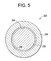
- the present invention is not limited in this regard as the composite annular seal assembly 70 may be employed with any type of bearing including but not limited to rolling bearings having balls and/or rollers, spherical plain bearings and journal bearings (see e.g., FIG. 5 ).
- the bearing 20 includes an inner race 30 and an outer race 50.
- the inner race 30 includes an inner race surface 36.
- the inner race surface 36 is generally convex.
- the inner race 30 defines a bore 34 extending therethrough.
- the bore 34 may be coaxial with a central axis 32 of the inner race 30.
- the bore 34 may be parallel to and radially displaced from the central axis 32 of the inner race 30, i.e. eccentric.
- a shaft (not shown) may be received in the bore 34.
- the shaft may be fixed about the central axis 32 relative to the inner race 30 by, for example, an interference fit between the shaft and the bore 34. It should be understood that although an interference fit is described in reference to the embodiment shown in FIG.
- the present invention is not limited in this regard and the shaft may be fixed relative to the bore 34 of the inner race 30 using other known techniques, including, for example, welding, thermal installation, pinning, or by providing a bore and shaft with similarly shaped angular cross-sections to inhibit rotation slippage.
- the inner race 30 and the shaft are the same component.
- the shaft may be rotatable relative to the inner race 30.
- the outer race 50 is annular about a central axis 52 of the outer race 50.
- the central axis 52 is coaxial with the central axis 32 of the inner race 30 when bearing is aligned. It should be understood that the central axis 32 of the inner race 30 and the central axis 52 of the outer race 50 may be parallel and laterally displaced, for example, when the bearing 20 is subject to a radial force.
- the outer race 50 defines a first outer race surface 54 and a second outer race surface 56, and each of the first and second outer race surfaces 54, 56 is generally opposite the inner race surface 36.
- Each of the first and second outer race surfaces 54, 56 is generally convex.
- the first outer race surface 54 and the inner race surface 36 define a first raceway 44 and the second outer race surface 56 and the inner race surface 36 define a second raceway 46. While the first and second outer race surfaces 54, 56 are shown and described as being generally convex, the present invention is not limited in this regard as in the embodiment shown in FIG. 5 wherein a journal bearing 220 has a concave race surface 254 of the outer race 250 and has a pin 230 with a convex outer race surface 236.
- the bearing 20 also comprises a plurality of first rollers 45 disposed in the first raceway 44, and a plurality of second rollers 47 disposed in the second raceway 46.
- Each of the plurality of first rollers 45 defines a first concave outer surface 48 that generally conforms to the convex surfaces of the inner race surface 36 and the first outer race surface 54.
- Each of the plurality of second rollers 47 defines a second concave outer surface 49 that generally conforms to the convex surfaces of the inner race surface 36 and the second outer race surface 56.
- This type of roller 45, 47 is generally referred to as an hourglass roller because of its generally concave surface extending between its ends.
- the bearing 20 further includes a cage 60 disposed between the inner race 30 and the outer race 50.
- the rollers 45, 47 and the cage 60 facilitate rotation of the outer race 50 relative to the inner race 30.
- the cage 60 also facilitates precessing of the rollers 45, 47 so that each of the rollers 45, 47 cycle through a load zone, even though the bearing 20 may be subject to an oscillatory rotation.
- a cage 60 is shown in the FIG. 1 , the present invention is not limited in this regard and a person of ordinary skill in the art and familiar with this disclosure will understand that other known methods of precessing or indexing may be employed.
- the outer race 50 defines a circumference 53 which includes a plurality of equally-spaced holes 51 therethrough for receiving a lubricant.
- the plurality of holes 51 provide fluid communication from an area outside the outer race 50 to a cavity 40 defined by the inner race 30 and outer race 50 and including the first raceway and the second raceway 44, 46.
- the plurality of holes 51 allow lubricant to be introduced and maintained in the first and second raceways 44, 46.
- the bearing 20 includes a first composite annular seal assembly 70 at or proximate to a first end 22 of the bearing 20 and a second composite annular seal assembly 80 at or proximate to a second end 24 of the bearing 20.
- the composite annular seal assemblies 70, 80 facilitate retention of lubricant in the first and second raceways 44, 46 and inhibit the ingress of contaminants into the first and second raceways 44, 46.
- the first composite annular seal assembly 70 extends from the first outer race surface 54 to the inner race surface 36; and the second composite annular seal assembly 80 extends from the second outer race surface 56 to the inner race surface 36.
- the composite annular seal assemblies 70, 80 are positioned axially adjacent to the cage 60.
- the composite annular seal assembly 80 is positioned axially adjacent to the cage 60 and spaced apart therefrom by a distance D9 as shown in FIG. 1 .
- the composite annular seal assemblies 70, 80 define a substantially flat configuration and are positioned substantially parallel to one another.
- the disclosed hourglass roller bearing 20 may be subject to oscillatory rotation about its central axis 32, 52.
- the bearing 20 is angularly displaceable.
- the central axis 52 of the outer race 50 may become angularly displaced from the central axis 32 of the inner race 30.
- the bearing 20 is configured to self-align.
- bearing seals currently on the marketplace tend to dislodge or fail when such a bearing is subject to such angular displacement.
- the inventors have discovered that the composite annular seal assembly 70, 80 disclosed in the present application overcomes one or more of these problems associated with known seals, and is better capable of retaining its position when the bearing is subject to angular displacement.
- the first composite annular seal assembly 70 is generally annular and defines a bore 71 extending therethrough. At least a portion of the inner race 30 extends through the bore 71 as shown in FIG. 1 .
- the first composite annular seal assembly 70 includes a first annular retaining ring 72 and a second annular retaining ring 74.
- the first and second annular retaining ring 72, 74 are generally annular, have a bore extending therethrough, and are often referred to as "seal caps.”
- the resilient ring 76 is disposed, i.e. sandwiched, between the first annular retaining ring 72 and the second annular retaining ring 74.
- a portion of the first annular retaining ring 72 is shown cut away to illustrate the resilient ring 76 positioned thereunder.
- a portion of the resilient ring 76 is cut away to illustrate the second annular retaining ring 74 thereunder.
- FIGS. 1 and 2B the resilient ring 76 is disposed, i.e. sandwiched, between the first annular retaining ring 72 and the second annular retaining ring 74.
- the composite annular seal assembly 70 defines an outer radial end 73 defined by a first radially outermost portion 72X of the first annular retaining ring 72, a second radially outermost portion 74X of the second annular retaining ring 72 and a third radially outermost portion 76X of the resilient ring 76.
- the first radially outermost portion 72X of the first annular retaining ring 72, the second radially outermost portion 74X of the second annular retaining ring 72 and the third radially outermost portion 76X are aligned with one another at the outer radial end 73.
- the resilient ring 76 extends from the third radially outermost portion 76X radially inward to an inner radial end 76Y.
- the inner radial end 76Y is positioned radially inward from an inner radial end 72Y of the first annular retaining ring 72 and is positioned radially inward from an inner radial end 74Y of the second annular retaining ring 74.
- the resilient ring 76 has a width W1 and the first annular retaining ring 72 and the second annular retaining ring 74 each have a width W2.
- the width W2 is less than the width W1.
- the width W2 is between about 70 percent and 90 percent of the width W1.
- the first end 73 of the composite annular seal assembly 70 is received in a radially inward facing groove 57 defined in the outer race 50 adjacent to or proximate the first outer race surface 54 and a lip 50K (see FIG.3 ) located at the first end 22 of the bearing 20.
- the groove 57 defines a channel width T1.
- the groove is defined by opposing side walls 57W and a base 57B extending between the opposing side walls 57W, as shown in FIG. 3A . As best shown in FIG.
- the first end 73 of the composite annular seal assembly 70 defines a thickness T2, wherein T2 includes a thickness T5 of the first annular retaining ring 72, a thickness T6 of the second annular retaining ring 74 and a thickness T4 of the resilient ring 76.
- T1 is greater than T2 to allow the first end 73 of the seal 70 to be snap-fit and retained in the groove 57 between the side walls 57W.
- the snap-fit is accomplished by laterally deflecting the composite annular seal 70 so that the first end 73 thereof is deflected radially inward to clear the lip 50KL and allow the first end 73 to snap into the groove 57, as described further herein with reference to FIG. 4 .
- the present invention is not limited in this regard as other means for securing the composite annular seal assembly 70 in the groove 57, such as for example, installing the first end 73 of the composite annular seal assembly 70 in the groove 57 by using an adhesive, or some other known means, may be used without departing from the broader aspects of the invention.
- the inner radial end 76Y of the resilient ring 76 slidingly engages (i.e., laterally and circumferentially) the inner race surface 36 of the inner race 30 adjacent to the first end 22 of the bearing 20 when the first composite annular seal assembly 70 is received in the groove 57 and the inner race 30 is disposed in the outer race 50.
- the first end 73 of the composite annular seal assembly 70 is received in the radial groove 57 defined in the outer race 50.
- the resilient ring 76 and the first and second retainers 72, 74 are axially secured inside the groove 57.
- the composite annular seal assembly 70 exhibits a tolerance stack-up such that retention inside the groove 57 by additional means is not necessary.
- the resilient ring 76 is more compressible and flexible than the first annular retaining ring 72 and the second annular retaining ring 74.
- resilient ring 76 is made from polytetrafluoroethylene (PTFE) and the first annular retaining ring 72 and the second annular retaining ring 74 are metallic.
- the first annular retaining ring 72 and the second annular retaining ring 74 are manufactured from a metal sheet stock, for example, stainless steel sheet stock and plain carbon steel sheet stock.
- the present invention is not limited in this regard as any materials may be used for the resilient ring 76, the first annular retaining ring 72 and the second annular retaining ring 74 without departing from the broader aspects disclosed herein.
- the thickness T4 of the resilient ring 76 is between about 0.010 inch and about 0.064 inch. In one embodiment, the thickness T5 of the first annular retaining ring 72 and the thickness T6 of the second annular retaining ring 74 are each about 0 0.008 inch to about 0.063 inch.
- the second composite annular seal assembly 80 is similar in design and construction to the first composite annular seal assembly 70, and is therefore not described in detail herein.
- the hourglass bearing is shown as having a first raceway 44 and a second raceway 46, the present invention is not limited in this regard, and the composite annular seal assembly in accordance with the present invention may by employed on an hourglass roller bearing having only a single row of rollers. It has been discovered that the benefit of the disclosed composite annular seal assembly design is that it facilitates the oscillatory movement of the bearing 20, while remaining stable and in position.
- the groove 57 has a diameter D3 measured between opposing base portions 57B.
- a diameter D1 is defined between points of contact P of the inner radial end 76Y of the resilient seal 76 with the inner race surface 36.
- the outer race 50 defines the lip 50K axially outward from the groove 57.
- the lip 50K defines a bore 50B having a diameter D2.
- the composite annular seal assembly 70 has an outside diameter D4 and the resilient ring 76 has an inside diameter D5.
- the diameter D2 of the bore 50B is less than the diameter D4 of the composite annular seal assembly 70 to allow the composite annular seal assembly 70 to be laterally elastically deformed, for example, by laterally deflecting the composite annular seal 70 into a deflected state as indicated by element number 70' in FIG.4 so that the first end 73 thereof is deflected radially inward to clear the lip 50K and allow the first end 73 to be snap-fit into the groove 57.
- the composite annular seal assembly 70 is shown and described as being seated in a portion of the outer race 50 and slidingly engaging the inner race 30, and having the resilient ring 76 extending from the third radially outermost portion 76X radially inward to an inner radial end 76Y, the inner radial end 76Y being positioned radially inward from an inner radial end 72Y of the first annular retaining ring 72 and being positioned radially inward from an inner radial end 74Y of the second annular retaining ring 74, the present invention is not limited in this regard.
- the composite annular seal 170 of FIG. 3B may be employed.
- the resilient ring 176 extends from a radially inner most portion 176X radially outward to an outer radial end 176Y.
- the outer radial end 176Y is positioned radially outward from an outer radial end 172Y of the first annular retaining ring 172 and is positioned radially outward from an outer radial end 174Y of the second annular retaining ring 174.
- the composite annular seal 170 is seated in the groove 158 and the radially outer most portion 176Y of the resilient ring 176 slidingly engages in the groove 157.
- the composite annular seal has a radial slit therein, for example, across the first annular retaining ring 172, the second annular retaining ring 174 and/or the resilient ring 176, to facilitate installation into the groove 158.
- the composite annular seal 170 is similar to the composite annular seal 70 shown and described herein with regard to thickness and materials. While the radially outer most portion 176Y of the resilient ring 176 is shown and described as slidingly engaging the groove 157, the present invention is not limited in this regard as the groove 157 may be eliminated and the radially outer most portion 176Y of the resilient ring 176 may slidingly engage the outer race surface 154, as shown in FIG. 3C .
- an aircraft wing includes a main fixed wing portion 1 and a single slotted trailing edge flap arrangement 2.
- the flap arrangement 2 includes a main element 3 and an auxiliary flap element 4 supported by the main flap element 3.
- the main flap element 3 is pivotally supported from the fixed wing portion 1 by a drop hinge linkage arrangement 5.
- the drop hinge linkage arrangement 5 includes a fixed strut 5a, a hinge point 5b and a drop link 5c.
- the fixed strut 5a is mounted to the fixed wing portion 1 and carries the hinge point 5b.
- the drop link 5c connects the main flap element 3 to the hinge point 5b.
- the auxiliary flap element 4 is supported by a rail 6 mounted to the main flap element 3.
- the auxiliary flap element 4 is slidably disposed upon the rail 6 for translational movement relative to the main flap element 3.
- the hinge point 5b has one of the bearings 20 (as described herein with reference to FIGS. 1-5 ) mounted therein.
- the bearing 20 includes the seal assembly 80 disposed therein as described herein with reference to FIGS. 1-5 . While the hinge point 5b is described as having one of the bearings 20 therein, the present invention is not limited in this regard as any number of the bearings 20 may be employed in the hinge point 5b. In one embodiment, the hinge point 5b has two of the bearings 20 installed therein; and in another embodiment, the hinge point 5b has two of the bearings 20 installed therein wherein the bearings 20 comprise different sized bearings.
- FIG. 6 shows the flap arrangement 2 in its retracted position.
- the main flap element 3 is stowed, tucked against the trailing edge of the fixed wing portion 1.
- the auxiliary flap element 4 is stowed in a forward position so as to be nested beneath the rear of the main flap element 3.
- the auxiliary flap element 4 completes the aerofoil profile of the main flap element 3.
- the trailing edges of the main and auxiliary flap elements 3 and 4 are substantially coincident when the auxiliary flap element 4 is in its retracted, stowed position.
- the main flap element 3 includes an actuator 7 (e.g., a linear or a rotary actuator), which is connected by a linkage arrangement (not shown) to the main flap element 3.
- an actuator 7 e.g., a linear or a rotary actuator
- the actuator 7 has one of the bearings 20 (as described herein with reference to FIGS. 1-5 ) disposed therein. While the actuator 7 is described as having one of the bearings 20 therein, the present invention is not limited in this regard as any number of the bearings 20 may be employed in the actuator 7. For example, two bearings 100 are employed in a linear actuator.
- the bearing 20 includes the seal assembly 80 disposed therein as described herein with reference to FIGS. 1-5 .
- the actuator 7 provides for movement of the main flap element 3 relative to the fixed wing portion 1. In one embodiment, the actuator 7 provides for movement of the drop hinge linkage arrangement 5 which, in turn, provides for movement of the main flap element 3 relative to the fixed wing portion 1.
- FIG. 7 illustrates the flap arrangement 2 in its partially extended position.
- the main flap element 3 is deployed by rotating it downwardly using the drop hinge mechanism 5. Movement of the main flap element 3 is effected by the rotary actuator 7 and the bearing 20 installed therein.
- the auxiliary flap element 4 can remain in its stowed, fully forward position as the main flap element 3 is deployed.
- the flap arrangement 2 functions substantially identically to a standard drop hinge flap arrangement.
- a slot 8 is opened up between the fixed wing portion 1 and the main flap element 3.
- the single slotted trailing edge flap arrangement 2 is configured for use with an aircraft such as, for example, an Airbus A-350 aircraft.
Landscapes
- Engineering & Computer Science (AREA)
- General Engineering & Computer Science (AREA)
- Mechanical Engineering (AREA)
- Aviation & Aerospace Engineering (AREA)
- Rolling Contact Bearings (AREA)
- Sealing Devices (AREA)
Abstract
Description
- This application claims the priority of the
U.S. patent application with the official file number 14/294,947, filed on June 03, 2014 - The present invention relates generally to a composite seal for use in bearings and more particularly to a composite annular seal assembly having a resilient ring disposed between (e.g., sandwiched between) two annular retaining rings, for use in hourglass type bearings for use in aircraft and more particularly in a drop linkage assembly of a trailing edge flap arrangement of such aircraft.
- There are many types of bearings that are used in various applications. Such bearings include journal bearings, roller bearings, spherical bearings and hourglass type bearings. In general, these bearings have an inner race that is disposed at least partially in an outer race. The inner race and outer race are movable relative to one another. There is an annular cavity between the inner race and the outer race that typically contains a lubricant. One well known problem with bearings is the ingress of debris and contaminants into the annular cavity which can cause premature failure of the bearings due to degradation of the lubrication. Moreover, operation of the bearing can cause the lubricant to inadvertently escape from the annular cavity.
- In an effort to mitigate the aforementioned problems, seals have been positioned across the annular cavity to maintain the lubricant in the cavity and to prevent the ingress of debris into the annular cavity. However, during operation, such seals become dislodged from the bearing and fail to function. In addition, such seals have often been too flexible, thereby allowing the seal to glide over debris and sweep the debris into the annular cavity.
- Bearings are typically used in aircraft wing flap arrangements. For example,
U.S. Patent No. 8,714,493 describes a trailing edge flap arrangement for an aircraft wing that includes a drop linkage arrangement that includes one or more bearings. The subject matter ofU.S. Patent No. 8,714,493 is incorporated by reference herein, in its entirety. - There is disclosed herein an edge flap arrangement for an aircraft wing, the arrangement comprising: a main flap element and an actuator for moving the main flap element relative to the wing; a linkage arrangement supporting the main flap element from the aircraft wing for movement relative to the wing, the linkage arrangement including a drop hinge link arrangement, the drop hinge link arrangement including a fixed strut secured to the aircraft wing and a drop link secured to the main flap element, the fixed strut and the drop link being pivotally connected by a hinge point; the hinge point comprising at least one bearing, the bearing comprising: an outer race having a first inner surface and an interior area; an inner race having an outer surface, a portion of the inner race being disposed in the interior area; an annular seal assembly snap-fit into the outer race, the annular seal assembly comprising: a first annular retaining ring defining a first radially outermost portion; a second annular retaining ring defining a second radially outermost portion; and a resilient ring defining a third radially outermost portion, the resilient ring being disposed between the first annular retaining ring and the second annular retaining ring; the first radially outermost portion, the second radially outermost portion and the third radially outermost portion being aligned with one another; the resilient ring projecting radially inward from the first annular retaining ring and the second annular retaining ring; and the resilient ring being more compressible and flexible than the first annular retaining ring and the second annular retaining ring.
- There is further disclosed herein a bearing installed in a wing flap actuator of an aircraft, the bearing comprising: an outer race having a first inner surface and an interior area; an inner race having an outer surface, a portion of the inner race being disposed in the interior area; an annular seal assembly snap-fit into the outer race, the annular seal assembly comprising: a first annular retaining ring defining a first radially outermost portion; a second annular retaining ring defining a second radially outermost portion; and a resilient ring defining a third radially outermost portion, the resilient ring being disposed between the first annular retaining ring and the second annular retaining ring; the first radially outermost portion, the second radially outermost portion and the third radially outermost portion being aligned with one another; the resilient ring projecting radially inward from the first annular retaining ring and the second annular retaining ring; and the resilient ring being more compressible and flexible than the first annular retaining ring and the second annular retaining ring.
- Further characteristics of the invention will become apparent from the description of the embodiments according to the invention together with the claims and the included drawings. Embodiments according to the invention can fulfill individual characteristics or a combination of several characteristics.
- The invention is described below, without restricting the general intent of the invention, based on exemplary embodiments, wherein reference is made expressly to the drawings with regard to the disclosure of all details according to the invention that are not explained in greater detail in the text.
-
-
FIG. 1 is a cross-sectional view of a portion of a bearing in accordance with one embodiment of the present invention; -
FIG. 2A is an edge view of a composite annular seal assembly for the bearing shown inFIG. 1 ; -
FIG. 2B is a side view of the composite annular seal assembly of the bearing shown inFIG. 2A ; -
FIG. 3A is an enlarged view of a portion of the composite annular seal ofFIG. 1 ; -
FIG. 3B is an enlarged view of another embodiment of the composite annular seal ofFIG.1 ; -
FIG. 3C illustrates an alternative to the embodiment ofFIG. 3B ; -
FIG. 4 is a cross sectional view of the bearing ofFIG. 1 with the composite seal assembly shown in a laterally deflected state during installation into the bearing; -
FIG. 5 is a cross sectional view of a journal bearing; -
FIG. 6 illustrates schematically a cross section through an aircraft wing having a trailing edge flap arrangement in accordance with the invention shown in its retracted position; and -
FIG. 7 illustrates the aircraft wing with the flap arrangement partially deployed. - These and other aspects are discussed below in more detail herein and are illustrated in the attached figures.
- In the drawings, the same or similar types of elements or respectively corresponding parts are provided with the same reference numbers in order to prevent the item from needing to be reintroduced.
- In reference to
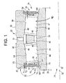
FIG. 1 , a roller bearingapparatus 20 in accordance with the present invention is shown. In the embodiment illustrated inFIG. 1 , thebearing 20 is an angular contact self-aligning bearing havinghourglass type rollers bearing 20 has a composite annular seal assembly 70 (e.g., a sandwich seal) positioned on opposing ends thereof, as described further herein. The compositeannular seal assembly 70 inhibits the ingress of contaminants into internal areas of thebearing 20 and egress of lubricant therefrom, as described herein. While the angular contact self-aligning bearing having hourglass type rollers is shown and described, the present invention is not limited in this regard as the compositeannular seal assembly 70 may be employed with any type of bearing including but not limited to rolling bearings having balls and/or rollers, spherical plain bearings and journal bearings (see e.g.,FIG. 5 ). - As shown in
FIG. 1 , thebearing 20 includes aninner race 30 and anouter race 50. Theinner race 30 includes aninner race surface 36. Theinner race surface 36 is generally convex. Theinner race 30 defines abore 34 extending therethrough. In some embodiments, thebore 34 may be coaxial with acentral axis 32 of theinner race 30. In other embodiments, thebore 34 may be parallel to and radially displaced from thecentral axis 32 of theinner race 30, i.e. eccentric. A shaft (not shown) may be received in thebore 34. The shaft may be fixed about thecentral axis 32 relative to theinner race 30 by, for example, an interference fit between the shaft and thebore 34. It should be understood that although an interference fit is described in reference to the embodiment shown inFIG. 1 , the present invention is not limited in this regard and the shaft may be fixed relative to thebore 34 of theinner race 30 using other known techniques, including, for example, welding, thermal installation, pinning, or by providing a bore and shaft with similarly shaped angular cross-sections to inhibit rotation slippage. In yet other embodiments, theinner race 30 and the shaft are the same component. In yet other embodiments, the shaft may be rotatable relative to theinner race 30. - The
outer race 50 is annular about acentral axis 52 of theouter race 50. Thecentral axis 52 is coaxial with thecentral axis 32 of theinner race 30 when bearing is aligned. It should be understood that thecentral axis 32 of theinner race 30 and thecentral axis 52 of theouter race 50 may be parallel and laterally displaced, for example, when thebearing 20 is subject to a radial force. - In the embodiment illustrated in
FIG. 1 , theouter race 50 defines a firstouter race surface 54 and a secondouter race surface 56, and each of the first and secondouter race surfaces inner race surface 36. Each of the first and secondouter race surfaces outer race surface 54 and theinner race surface 36 define afirst raceway 44 and the secondouter race surface 56 and theinner race surface 36 define asecond raceway 46. While the first and second outer race surfaces 54, 56 are shown and described as being generally convex, the present invention is not limited in this regard as in the embodiment shown inFIG. 5 wherein a journal bearing 220 has aconcave race surface 254 of theouter race 250 and has apin 230 with a convexouter race surface 236. - As illustrated in
FIG. 1 , the bearing 20 also comprises a plurality offirst rollers 45 disposed in thefirst raceway 44, and a plurality ofsecond rollers 47 disposed in thesecond raceway 46. Each of the plurality offirst rollers 45 defines a first concaveouter surface 48 that generally conforms to the convex surfaces of theinner race surface 36 and the firstouter race surface 54. Each of the plurality ofsecond rollers 47 defines a second concaveouter surface 49 that generally conforms to the convex surfaces of theinner race surface 36 and the secondouter race surface 56. This type ofroller cage 60 disposed between theinner race 30 and theouter race 50. Therollers cage 60 facilitate rotation of theouter race 50 relative to theinner race 30. Thecage 60 also facilitates precessing of therollers rollers bearing 20 may be subject to an oscillatory rotation. Although acage 60 is shown in theFIG. 1 , the present invention is not limited in this regard and a person of ordinary skill in the art and familiar with this disclosure will understand that other known methods of precessing or indexing may be employed. - The
outer race 50 defines acircumference 53 which includes a plurality of equally-spacedholes 51 therethrough for receiving a lubricant. The plurality ofholes 51 provide fluid communication from an area outside theouter race 50 to acavity 40 defined by theinner race 30 andouter race 50 and including the first raceway and thesecond raceway holes 51 allow lubricant to be introduced and maintained in the first andsecond raceways - As shown in
FIG. 1 , thebearing 20 includes a first compositeannular seal assembly 70 at or proximate to afirst end 22 of thebearing 20 and a second compositeannular seal assembly 80 at or proximate to asecond end 24 of thebearing 20. The compositeannular seal assemblies second raceways second raceways annular seal assembly 70 extends from the firstouter race surface 54 to theinner race surface 36; and the second compositeannular seal assembly 80 extends from the secondouter race surface 56 to theinner race surface 36. The compositeannular seal assemblies cage 60. In one embodiment as shown with respect to the second compositeannular seal assembly 80, the compositeannular seal assembly 80 is positioned axially adjacent to thecage 60 and spaced apart therefrom by a distance D9 as shown inFIG. 1 . In one embodiment, the compositeannular seal assemblies hourglass roller bearing 20 may be subject to oscillatory rotation about itscentral axis bearing 20 is angularly displaceable. For example, thecentral axis 52 of theouter race 50 may become angularly displaced from thecentral axis 32 of theinner race 30. To the extent the bearing 20 becomes angularly displaced as a result of an external force, thebearing 20 is configured to self-align. The inventors have discovered that bearing seals currently on the marketplace tend to dislodge or fail when such a bearing is subject to such angular displacement. The inventors have discovered that the compositeannular seal assembly - As shown in
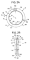
FIG. 2A , the first compositeannular seal assembly 70 is generally annular and defines abore 71 extending therethrough. At least a portion of theinner race 30 extends through thebore 71 as shown inFIG. 1 . The first compositeannular seal assembly 70 includes a firstannular retaining ring 72 and a second annular retainingring 74. The first and second annular retainingring - Referring to
FIGS. 1 and2B , theresilient ring 76 is disposed, i.e. sandwiched, between the firstannular retaining ring 72 and the second annular retainingring 74. In the front view of the compositeannular seal 70 ofFIG. 2A a portion of the firstannular retaining ring 72 is shown cut away to illustrate theresilient ring 76 positioned thereunder. InFIG. 2A a portion of theresilient ring 76 is cut away to illustrate the second annular retainingring 74 thereunder. As shown inFIGS. 2A, 2B and3A , The compositeannular seal assembly 70 defines an outerradial end 73 defined by a first radiallyoutermost portion 72X of the firstannular retaining ring 72, a second radiallyoutermost portion 74X of the second annular retainingring 72 and a third radiallyoutermost portion 76X of theresilient ring 76. The first radiallyoutermost portion 72X of the firstannular retaining ring 72, the second radiallyoutermost portion 74X of the second annular retainingring 72 and the third radiallyoutermost portion 76X are aligned with one another at the outerradial end 73. - As best shown in
FIGS. 1 ,2A and3A , theresilient ring 76 extends from the third radiallyoutermost portion 76X radially inward to an innerradial end 76Y. The innerradial end 76Y is positioned radially inward from an innerradial end 72Y of the firstannular retaining ring 72 and is positioned radially inward from an innerradial end 74Y of the second annular retainingring 74. In one embodiment theresilient ring 76 has a width W1 and the firstannular retaining ring 72 and the second annular retainingring 74 each have a width W2. The width W2 is less than the width W1. In one embodiment, the width W2 is between about 70 percent and 90 percent of the width W1. - As shown in
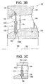
FIG. 1 , thefirst end 73 of the compositeannular seal assembly 70 is received in a radially inward facinggroove 57 defined in theouter race 50 adjacent to or proximate the firstouter race surface 54 and alip 50K (seeFIG.3 ) located at thefirst end 22 of thebearing 20. In the embodiment shown inFIG. 1 , thegroove 57 defines a channel width T1. The groove is defined by opposingside walls 57W and abase 57B extending between the opposingside walls 57W, as shown inFIG. 3A . As best shown inFIG. 2B , thefirst end 73 of the compositeannular seal assembly 70 defines a thickness T2, wherein T2 includes a thickness T5 of the firstannular retaining ring 72, a thickness T6 of the second annular retainingring 74 and a thickness T4 of theresilient ring 76. In one embodiment, T1 is greater than T2 to allow thefirst end 73 of theseal 70 to be snap-fit and retained in thegroove 57 between theside walls 57W. The snap-fit is accomplished by laterally deflecting the compositeannular seal 70 so that thefirst end 73 thereof is deflected radially inward to clear the lip 50KL and allow thefirst end 73 to snap into thegroove 57, as described further herein with reference toFIG. 4 . - While the composite
annular seal assembly 70 is described as being seated and secured in thegroove 57 using a snap-fit assembly, the present invention is not limited in this regard as other means for securing the compositeannular seal assembly 70 in thegroove 57, such as for example, installing thefirst end 73 of the compositeannular seal assembly 70 in thegroove 57 by using an adhesive, or some other known means, may be used without departing from the broader aspects of the invention. - The inner
radial end 76Y of theresilient ring 76 slidingly engages (i.e., laterally and circumferentially) theinner race surface 36 of theinner race 30 adjacent to thefirst end 22 of thebearing 20 when the first compositeannular seal assembly 70 is received in thegroove 57 and theinner race 30 is disposed in theouter race 50. As described above, thefirst end 73 of the compositeannular seal assembly 70 is received in theradial groove 57 defined in theouter race 50. As a result, theresilient ring 76 and the first andsecond retainers groove 57. The compositeannular seal assembly 70 exhibits a tolerance stack-up such that retention inside thegroove 57 by additional means is not necessary. However, use of such additional means for axial retention of theresilient ring 76 and the first and second annular retaining rings 72, 74 inside thegroove 57, such as use of adhesives, is considered within the scope of the invention. Similarly, theresilient ring 76 is retained between the first and second annular retainingring groove 57 such that additional means is not necessary. However, use of such additional means for retaining theresilient ring 76 between the first and second annular retainingring - The
resilient ring 76 is more compressible and flexible than the firstannular retaining ring 72 and the second annular retainingring 74. For example,resilient ring 76 is made from polytetrafluoroethylene (PTFE) and the firstannular retaining ring 72 and the second annular retainingring 74 are metallic. In one embodiment the firstannular retaining ring 72 and the second annular retainingring 74 are manufactured from a metal sheet stock, for example, stainless steel sheet stock and plain carbon steel sheet stock. However, the present invention is not limited in this regard as any materials may be used for theresilient ring 76, the firstannular retaining ring 72 and the second annular retainingring 74 without departing from the broader aspects disclosed herein. - Depending on the size of the
bearing 20, the thickness T4 of theresilient ring 76 is between about 0.010 inch and about 0.064 inch. In one embodiment, the thickness T5 of the firstannular retaining ring 72 and the thickness T6 of the second annular retainingring 74 are each about 0 0.008 inch to about 0.063 inch. - The second composite
annular seal assembly 80 is similar in design and construction to the first compositeannular seal assembly 70, and is therefore not described in detail herein. Although the hourglass bearing is shown as having afirst raceway 44 and asecond raceway 46, the present invention is not limited in this regard, and the composite annular seal assembly in accordance with the present invention may by employed on an hourglass roller bearing having only a single row of rollers. It has been discovered that the benefit of the disclosed composite annular seal assembly design is that it facilitates the oscillatory movement of thebearing 20, while remaining stable and in position. - Referring to
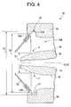
FIG. 4 , thegroove 57 has a diameter D3 measured between opposingbase portions 57B. A diameter D1 is defined between points of contact P of the innerradial end 76Y of theresilient seal 76 with theinner race surface 36. Theouter race 50 defines thelip 50K axially outward from thegroove 57. Thelip 50K defines abore 50B having a diameter D2. As shown inFIG. 2A , the compositeannular seal assembly 70 has an outside diameter D4 and theresilient ring 76 has an inside diameter D5. In one embodiment, the diameter D2 of thebore 50B is less than the diameter D4 of the compositeannular seal assembly 70 to allow the compositeannular seal assembly 70 to be laterally elastically deformed, for example, by laterally deflecting the compositeannular seal 70 into a deflected state as indicated by element number 70' inFIG.4 so that thefirst end 73 thereof is deflected radially inward to clear thelip 50K and allow thefirst end 73 to be snap-fit into thegroove 57. While the compositeannular seal assembly 70 is shown and described as being seated in a portion of theouter race 50 and slidingly engaging theinner race 30, and having theresilient ring 76 extending from the third radiallyoutermost portion 76X radially inward to an innerradial end 76Y, the innerradial end 76Y being positioned radially inward from an innerradial end 72Y of the firstannular retaining ring 72 and being positioned radially inward from an innerradial end 74Y of the second annular retainingring 74, the present invention is not limited in this regard. For example, the compositeannular seal 170 ofFIG. 3B may be employed. Thebearing 120 and compositeannular seal 170 ofFIG. 3B are similar to thebearing 20 and compositeannular seal 70 ofFIG. 3A , therefore like elements are assigned like reference numbers preceded by thenumeral 1. Theresilient ring 176 extends from a radially innermost portion 176X radially outward to an outerradial end 176Y. The outerradial end 176Y is positioned radially outward from an outerradial end 172Y of the firstannular retaining ring 172 and is positioned radially outward from an outerradial end 174Y of the secondannular retaining ring 174. The compositeannular seal 170 is seated in thegroove 158 and the radially outermost portion 176Y of theresilient ring 176 slidingly engages in thegroove 157. In one embodiment, the composite annular seal has a radial slit therein, for example, across the firstannular retaining ring 172, the secondannular retaining ring 174 and/or theresilient ring 176, to facilitate installation into thegroove 158. The compositeannular seal 170 is similar to the compositeannular seal 70 shown and described herein with regard to thickness and materials. While the radially outermost portion 176Y of theresilient ring 176 is shown and described as slidingly engaging thegroove 157, the present invention is not limited in this regard as thegroove 157 may be eliminated and the radially outermost portion 176Y of theresilient ring 176 may slidingly engage theouter race surface 154, as shown inFIG. 3C . - Referring to
FIG. 6 , an aircraft wing includes a mainfixed wing portion 1 and a single slotted trailing edge flap arrangement 2. The flap arrangement 2 includes a main element 3 and an auxiliary flap element 4 supported by the main flap element 3. The main flap element 3 is pivotally supported from the fixedwing portion 1 by a drop hinge linkage arrangement 5. The drop hinge linkage arrangement 5 includes a fixed strut 5a, ahinge point 5b and a drop link 5c. The fixed strut 5a is mounted to the fixedwing portion 1 and carries thehinge point 5b. The drop link 5c connects the main flap element 3 to thehinge point 5b. The auxiliary flap element 4 is supported by a rail 6 mounted to the main flap element 3. The auxiliary flap element 4 is slidably disposed upon the rail 6 for translational movement relative to the main flap element 3. Thehinge point 5b has one of the bearings 20 (as described herein with reference toFIGS. 1-5 ) mounted therein. Thebearing 20 includes theseal assembly 80 disposed therein as described herein with reference toFIGS. 1-5 . While thehinge point 5b is described as having one of thebearings 20 therein, the present invention is not limited in this regard as any number of thebearings 20 may be employed in thehinge point 5b. In one embodiment, thehinge point 5b has two of thebearings 20 installed therein; and in another embodiment, thehinge point 5b has two of thebearings 20 installed therein wherein thebearings 20 comprise different sized bearings. -
FIG. 6 shows the flap arrangement 2 in its retracted position. The main flap element 3 is stowed, tucked against the trailing edge of the fixedwing portion 1. The auxiliary flap element 4 is stowed in a forward position so as to be nested beneath the rear of the main flap element 3. When stowed, the auxiliary flap element 4 completes the aerofoil profile of the main flap element 3. The trailing edges of the main and auxiliary flap elements 3 and 4 are substantially coincident when the auxiliary flap element 4 is in its retracted, stowed position. As further shown inFIG. 6 , the main flap element 3 includes an actuator 7 (e.g., a linear or a rotary actuator), which is connected by a linkage arrangement (not shown) to the main flap element 3. In one embodiment, the actuator 7 has one of the bearings 20 (as described herein with reference toFIGS. 1-5 ) disposed therein. While the actuator 7 is described as having one of thebearings 20 therein, the present invention is not limited in this regard as any number of thebearings 20 may be employed in the actuator 7. For example, two bearings 100 are employed in a linear actuator. Thebearing 20 includes theseal assembly 80 disposed therein as described herein with reference toFIGS. 1-5 . The actuator 7 provides for movement of the main flap element 3 relative to the fixedwing portion 1. In one embodiment, the actuator 7 provides for movement of the drop hinge linkage arrangement 5 which, in turn, provides for movement of the main flap element 3 relative to the fixedwing portion 1. -
FIG. 7 illustrates the flap arrangement 2 in its partially extended position. The main flap element 3 is deployed by rotating it downwardly using the drop hinge mechanism 5. Movement of the main flap element 3 is effected by the rotary actuator 7 and thebearing 20 installed therein. As can be seen fromFIG. 7 , the auxiliary flap element 4 can remain in its stowed, fully forward position as the main flap element 3 is deployed. In this partially extended configuration, the flap arrangement 2 functions substantially identically to a standard drop hinge flap arrangement. With the main flap element 3 extended by rotation about the drop hinge mechanism 5, a slot 8 is opened up between the fixedwing portion 1 and the main flap element 3. The single slotted flap configuration shown inFIG. 7 enables high pressure air from the lower wing surface to pass through the slot 8 to energize the boundary layer over the upper surface of the main flap element 3 so as to postpone stall in a conventional manner. The single slotted trailing edge flap arrangement 2 is configured for use with an aircraft such as, for example, an Airbus A-350 aircraft. - While the present disclosure has been described with reference to various exemplary embodiments, it will be understood by those skilled in the art that various changes may be made and equivalents may be substituted for elements thereof without departing from the scope of the invention. In addition, many modifications may be made to adapt a particular situation or material to the teachings of the invention without departing from the essential scope thereof. Therefore, it is intended that the invention not be limited to the particular embodiment disclosed as the best mode contemplated for carrying out this invention, but that the invention will include all embodiments falling within the scope of the appended claims.
- All named characteristics, including those taken from the drawings alone, and individual characteristics, which are disclosed in combination with other characteristics, are considered alone and in combination as important to the invention. Embodiments according to the invention can be fulfilled through individual characteristics or a combination of several characteristics. Features which are combined with the wording "in particular" or "especially" are to be treated as preferred embodiments.
Claims (12)
- An edge flap arrangement for an aircraft wing, the arrangement comprising:a main flap element and an actuator for moving the main flap element relative to the aircraft wing;a linkage arrangement supporting the main flap element from the aircraft wing for movement relative to the aircraft wing, the linkage arrangement including a drop hinge link arrangement, the drop hinge link arrangement including a fixed strut secured to the aircraft wing and a drop link secured to the main flap element, the fixed strut and the drop link being pivotally connected by a hinge point;the hinge point comprising at least a first bearing, the first bearing comprising:an outer race having a first inner surface and an interior area;an inner race having an outer surface, a portion of the inner race being disposed in the interior area;an annular seal assembly snap-fit into the outer race, the annular seal assembly comprising:a first annular retaining ring defining a first radially outermost portion;a second annular retaining ring defining a second radially outermost portion; anda resilient ring defining a third radially outermost portion, the resilient ring being disposed between the first annular retaining ring and the second annular retaining ring;the first radially outermost portion, the second radially outermost portion and the third radially outermost portion being aligned with one another;the resilient ring projecting radially inward from the first annular retaining ring and the second annular retaining ring; andthe resilient ring being more compressible and flexible than the first annular retaining ring and the second annular retaining ring.
- The edge flap arrangement of claim 1, further comprising:at least a second bearing installed in the actuator for moving the main flap element relative to the aircraft wing, the at least one second bearing comprising:an outer race having a first inner surface and an interior area;an inner race having an outer surface, a portion of the inner race being disposed in the interior area;an annular seal assembly snap-fit into the outer race, the annular seal assembly comprising:a first annular retaining ring defining a first radially outermost portion;a second annular retaining ring defining a second radially outermost portion; anda resilient ring defining a third radially outermost portion, the resilient ring being disposed between the first annular retaining ring and the second annular retaining ring;the first radially outermost portion, the second radially outermost portion and the third radially outermost portion being aligned with one another;the resilient ring projecting radially inward from the first annular retaining ring and the second annular retaining ring; andthe resilient ring being more compressible and flexible than the first annular retaining ring and the second annular retaining ring.
- The edge flap arrangement of claim 1 or 2, wherein the hinge point comprises a plurality of first bearings.
- The edge flap arrangement of claim 2 wherein the actuator comprises a plurality of second bearings.
- The edge flap arrangement of one of claims 1 to 4 wherein the edge flap is for a trailing edge of a wing of an aircraft.
- The edge flap arrangement of one of claims 1 to 5 wherein the aircraft is an Airbus A-350 aircraft.
- The edge flap arrangement of one of claims 1 to 6, the first bearing further comprising:a plurality of first hourglass rollers, each of the plurality of first hourglass rollers having a generally concave outer surface, the plurality of first hourglass rollers being disposed between the inner race and the outer race;the first inner surface being convex and the outer surface being convex; andeach of the plurality of first hourglass rollers engaging the outer surface and the first inner surface.
- The edge flap arrangement of claim 7, the first bearing further comprising:a second inner surface defined by the outer race, the second inner surface being convex;a plurality of second hourglass rollers, each of the plurality of second hourglass rollers having a generally concave outer surface, the plurality of second hourglass rollers being disposed between the inner race and the outer race; andeach of the plurality of second hourglass rollers engaging the outer surface and the second inner surface.
- The edge flap arrangement of one of claims 1 to 8, the first bearing further comprising:a plurality of first hourglass rollers, each of the plurality of first hourglass rollers having a generally concave outer surface, the plurality of first hourglass rollers being disposed between the inner race and the outer race;the first inner surface being convex and the outer surface being convex; andeach of the plurality of first hourglass rollers engaging the outer surface and the first inner surface.
- The edge flap arrangement of claim 9, the first bearing further comprising:a second inner surface defined by the outer race, the second inner surface being convex;a plurality of second hourglass rollers, each of the plurality of second hourglass rollers having a generally concave outer surface, the plurality of second hourglass rollers being disposed between the inner race and the outer race; andeach of the plurality of second hourglass rollers engaging the outer surface and the second inner surface.
- A bearing installed in a wing flap actuator of an aircraft, the bearing comprising:an outer race having a first inner surface and an interior area;an inner race having an outer surface, a portion of the inner race being disposed in the interior area;an annular seal assembly snap-fit into the outer race, the annular seal assembly comprising:a first annular retaining ring defining a first radially outermost portion;a second annular retaining ring defining a second radially outermost portion; anda resilient ring defining a third radially outermost portion, the resilient ring being disposed between the first annular retaining ring and the second annular retaining ring;the first radially outermost portion, the second radially outermost portion and the third radially outermost portion being aligned with one another;the resilient ring projecting radially inward from the first annular retaining ring and the second annular retaining ring; andthe resilient ring being more compressible and flexible than the first annular retaining ring and the second annular retaining ring.
- The bearing according to claim 11 wherein the wing flap is for a trailing edge of a wing of an aircraft.
Applications Claiming Priority (2)
| Application Number | Priority Date | Filing Date | Title |
|---|---|---|---|
| US14/194,016 US20140248016A1 (en) | 2013-03-01 | 2014-02-28 | Composite annular seal assembly for bearings |
| US14/294,947 US9227720B2 (en) | 2013-03-01 | 2014-06-03 | Composite annular seal assembly for bearings in aircraft |
Publications (3)
| Publication Number | Publication Date |
|---|---|
| EP2927115A2 true EP2927115A2 (en) | 2015-10-07 |
| EP2927115A3 EP2927115A3 (en) | 2016-01-13 |
| EP2927115B1 EP2927115B1 (en) | 2019-05-08 |
Family
ID=51178636
Family Applications (1)
| Application Number | Title | Priority Date | Filing Date |
|---|---|---|---|
| EP14171081.4A Active EP2927115B1 (en) | 2014-02-28 | 2014-06-04 | An edge flap arrangement for an aircraft wing |
Country Status (2)
| Country | Link |
|---|---|
| EP (1) | EP2927115B1 (en) |
| KR (1) | KR101677080B1 (en) |
Cited By (1)
| Publication number | Priority date | Publication date | Assignee | Title |
|---|---|---|---|---|
| EP3748182A1 (en) * | 2019-06-04 | 2020-12-09 | IMO Holding GmbH | Roller bearing arrangement with a sealing device for sealing the bearing gap |
Citations (1)
| Publication number | Priority date | Publication date | Assignee | Title |
|---|---|---|---|---|
| US8714493B2 (en) | 2009-11-27 | 2014-05-06 | Airbus Operations Limited | Trailing edge flap |
Family Cites Families (7)
| Publication number | Priority date | Publication date | Assignee | Title |
|---|---|---|---|---|
| US2764432A (en) * | 1952-06-04 | 1956-09-25 | Fafnir Bearing Co | Bearing seal |
| US2728616A (en) * | 1953-11-24 | 1955-12-27 | Fafnir Bearing Co | Bearing |
| US5441351A (en) * | 1993-10-26 | 1995-08-15 | Rexnord Corporation | Full complement self-aligning roller bearing |
| US6394656B1 (en) * | 2000-09-05 | 2002-05-28 | Rexnord Corporation | Retainerless precessing roller bearing |
| DE102005062919A1 (en) * | 2005-12-29 | 2007-07-12 | Airbus Deutschland Gmbh | Airfoil for aircraft, has flap attached to supports and rotates with respect to axis during rotation of supports relative to wingbox, computer evaluating output signals from sensors and controlling drives on basis of evaluation |
| GB0920969D0 (en) * | 2009-11-27 | 2010-01-13 | Airbus Operations Ltd | Trailing edge flap |
| EP2844886B1 (en) * | 2012-04-30 | 2018-11-07 | Roller Bearing Company of America, Inc. | Hybrid bearing assembly with rolling elements and plain bearing |
-
2014
- 2014-06-04 EP EP14171081.4A patent/EP2927115B1/en active Active
-
2015
- 2015-06-02 KR KR1020150077790A patent/KR101677080B1/en active IP Right Grant
Patent Citations (1)
| Publication number | Priority date | Publication date | Assignee | Title |
|---|---|---|---|---|
| US8714493B2 (en) | 2009-11-27 | 2014-05-06 | Airbus Operations Limited | Trailing edge flap |
Cited By (1)
| Publication number | Priority date | Publication date | Assignee | Title |
|---|---|---|---|---|
| EP3748182A1 (en) * | 2019-06-04 | 2020-12-09 | IMO Holding GmbH | Roller bearing arrangement with a sealing device for sealing the bearing gap |
Also Published As
| Publication number | Publication date |
|---|---|
| EP2927115A3 (en) | 2016-01-13 |
| KR20150139455A (en) | 2015-12-11 |
| EP2927115B1 (en) | 2019-05-08 |
| KR101677080B1 (en) | 2016-11-17 |
Similar Documents
| Publication | Publication Date | Title |
|---|---|---|
| US20140339369A1 (en) | Composite annular seal assembly for bearings in aircraft | |
| US9561845B2 (en) | Bearing installed on an aircraft structure | |
| EP2354579B1 (en) | Self aligning double-row roller bearing with sealing means. | |
| EP2894359B1 (en) | Roller profile for hourglass roller bearings in aircraft | |
| US11149788B2 (en) | Hybrid bearing assembly with rolling elements and plain bearing | |
| US20140248016A1 (en) | Composite annular seal assembly for bearings | |
| EP2957781B1 (en) | Support structure of a flap at the rear of an aircraft wing with double-row concave roller bearing | |
| WO2010043248A1 (en) | Seal for rolling bearing, in particular for rolling bearing used in a wind turbine | |
| US9863468B2 (en) | Rod end wear prevention | |
| US8851755B2 (en) | Self-aligning track roller bearing | |
| EP2952758A1 (en) | Corrosion resistant bearing | |
| DE102010025803B4 (en) | sealing arrangement | |
| EP2927115B1 (en) | An edge flap arrangement for an aircraft wing | |
| JP5712641B2 (en) | Thrust bearing with drop prevention protrusion | |
| US9657778B1 (en) | Convertible cage for ball bearing and associated bearing | |
| US9957038B2 (en) | Propeller assemblies and propeller blade retention assembly | |
| EP3336370B1 (en) | Cam follower and yoke roller assemblies | |
| EP2981724B1 (en) | Spherical bearing and method of making the same | |
| KR101349802B1 (en) | Ball bearing | |
| CN111911528A (en) | Vibrating screen self-aligning roller bearing | |
| EP3034899B1 (en) | Seal for self aligning roller bearing | |
| JP2016191410A (en) | Track roller bearing | |
| EP3001054A1 (en) | Conical roller bearing | |
| KR101349803B1 (en) | Ball bearing | |
| KR101349804B1 (en) | Ball bearing |
Legal Events
| Date | Code | Title | Description |
|---|---|---|---|
| PUAI | Public reference made under article 153(3) epc to a published international application that has entered the european phase |
Free format text: ORIGINAL CODE: 0009012 |
|
| 17P | Request for examination filed |
Effective date: 20140604 |
|
| AK | Designated contracting states |
Kind code of ref document: A2 Designated state(s): AL AT BE BG CH CY CZ DE DK EE ES FI FR GB GR HR HU IE IS IT LI LT LU LV MC MK MT NL NO PL PT RO RS SE SI SK SM TR |
|
| AX | Request for extension of the european patent |
Extension state: BA ME |
|
| PUAL | Search report despatched |
Free format text: ORIGINAL CODE: 0009013 |
|
| AK | Designated contracting states |
Kind code of ref document: A3 Designated state(s): AL AT BE BG CH CY CZ DE DK EE ES FI FR GB GR HR HU IE IS IT LI LT LU LV MC MK MT NL NO PL PT RO RS SE SI SK SM TR |
|
| AX | Request for extension of the european patent |
Extension state: BA ME |
|
| RIC1 | Information provided on ipc code assigned before grant |
Ipc: B64C 9/20 20060101AFI20151208BHEP Ipc: F16C 33/78 20060101ALI20151208BHEP |
|
| RBV | Designated contracting states (corrected) |
Designated state(s): AL AT BE BG CH CY CZ DE DK EE ES FI FR GB GR HR HU IE IS IT LI LT LU LV MC MK MT NL NO PL PT RO RS SE SI SK SM TR |
|
| REG | Reference to a national code |
Ref country code: DE Ref legal event code: R079 Ref document number: 602014046146 Country of ref document: DE Free format text: PREVIOUS MAIN CLASS: B64C0009200000 Ipc: F16C0023080000 |
|
| RIC1 | Information provided on ipc code assigned before grant |
Ipc: F16C 23/08 20060101AFI20181220BHEP Ipc: F16C 19/38 20060101ALI20181220BHEP Ipc: F16C 11/06 20060101ALI20181220BHEP Ipc: B64C 9/20 20060101ALI20181220BHEP Ipc: F16C 33/78 20060101ALI20181220BHEP |
|
| GRAP | Despatch of communication of intention to grant a patent |
Free format text: ORIGINAL CODE: EPIDOSNIGR1 |
|
| STAA | Information on the status of an ep patent application or granted ep patent |
Free format text: STATUS: GRANT OF PATENT IS INTENDED |
|
| INTG | Intention to grant announced |
Effective date: 20190129 |
|
| GRAS | Grant fee paid |
Free format text: ORIGINAL CODE: EPIDOSNIGR3 |
|
| GRAA | (expected) grant |
Free format text: ORIGINAL CODE: 0009210 |
|
| STAA | Information on the status of an ep patent application or granted ep patent |
Free format text: STATUS: THE PATENT HAS BEEN GRANTED |
|
| AK | Designated contracting states |
Kind code of ref document: B1 Designated state(s): AL AT BE BG CH CY CZ DE DK EE ES FI FR GB GR HR HU IE IS IT LI LT LU LV MC MK MT NL NO PL PT RO RS SE SI SK SM TR |
|
| REG | Reference to a national code |
Ref country code: GB Ref legal event code: FG4D |
|
| REG | Reference to a national code |
Ref country code: CH Ref legal event code: EP Ref country code: AT Ref legal event code: REF Ref document number: 1130582 Country of ref document: AT Kind code of ref document: T Effective date: 20190515 |
|
| REG | Reference to a national code |
Ref country code: DE Ref legal event code: R096 Ref document number: 602014046146 Country of ref document: DE Ref country code: IE Ref legal event code: FG4D |
|
| REG | Reference to a national code |
Ref country code: NL Ref legal event code: MP Effective date: 20190508 |
|
| REG | Reference to a national code |
Ref country code: LT Ref legal event code: MG4D |
|
| PG25 | Lapsed in a contracting state [announced via postgrant information from national office to epo] |
Ref country code: HR Free format text: LAPSE BECAUSE OF FAILURE TO SUBMIT A TRANSLATION OF THE DESCRIPTION OR TO PAY THE FEE WITHIN THE PRESCRIBED TIME-LIMIT Effective date: 20190508 Ref country code: LT Free format text: LAPSE BECAUSE OF FAILURE TO SUBMIT A TRANSLATION OF THE DESCRIPTION OR TO PAY THE FEE WITHIN THE PRESCRIBED TIME-LIMIT Effective date: 20190508 Ref country code: ES Free format text: LAPSE BECAUSE OF FAILURE TO SUBMIT A TRANSLATION OF THE DESCRIPTION OR TO PAY THE FEE WITHIN THE PRESCRIBED TIME-LIMIT Effective date: 20190508 Ref country code: NL Free format text: LAPSE BECAUSE OF FAILURE TO SUBMIT A TRANSLATION OF THE DESCRIPTION OR TO PAY THE FEE WITHIN THE PRESCRIBED TIME-LIMIT Effective date: 20190508 Ref country code: FI Free format text: LAPSE BECAUSE OF FAILURE TO SUBMIT A TRANSLATION OF THE DESCRIPTION OR TO PAY THE FEE WITHIN THE PRESCRIBED TIME-LIMIT Effective date: 20190508 Ref country code: SE Free format text: LAPSE BECAUSE OF FAILURE TO SUBMIT A TRANSLATION OF THE DESCRIPTION OR TO PAY THE FEE WITHIN THE PRESCRIBED TIME-LIMIT Effective date: 20190508 Ref country code: AL Free format text: LAPSE BECAUSE OF FAILURE TO SUBMIT A TRANSLATION OF THE DESCRIPTION OR TO PAY THE FEE WITHIN THE PRESCRIBED TIME-LIMIT Effective date: 20190508 Ref country code: NO Free format text: LAPSE BECAUSE OF FAILURE TO SUBMIT A TRANSLATION OF THE DESCRIPTION OR TO PAY THE FEE WITHIN THE PRESCRIBED TIME-LIMIT Effective date: 20190808 Ref country code: PT Free format text: LAPSE BECAUSE OF FAILURE TO SUBMIT A TRANSLATION OF THE DESCRIPTION OR TO PAY THE FEE WITHIN THE PRESCRIBED TIME-LIMIT Effective date: 20190908 |
|
| PG25 | Lapsed in a contracting state [announced via postgrant information from national office to epo] |
Ref country code: BG Free format text: LAPSE BECAUSE OF FAILURE TO SUBMIT A TRANSLATION OF THE DESCRIPTION OR TO PAY THE FEE WITHIN THE PRESCRIBED TIME-LIMIT Effective date: 20190808 Ref country code: GR Free format text: LAPSE BECAUSE OF FAILURE TO SUBMIT A TRANSLATION OF THE DESCRIPTION OR TO PAY THE FEE WITHIN THE PRESCRIBED TIME-LIMIT Effective date: 20190809 Ref country code: LV Free format text: LAPSE BECAUSE OF FAILURE TO SUBMIT A TRANSLATION OF THE DESCRIPTION OR TO PAY THE FEE WITHIN THE PRESCRIBED TIME-LIMIT Effective date: 20190508 Ref country code: RS Free format text: LAPSE BECAUSE OF FAILURE TO SUBMIT A TRANSLATION OF THE DESCRIPTION OR TO PAY THE FEE WITHIN THE PRESCRIBED TIME-LIMIT Effective date: 20190508 |
|
| REG | Reference to a national code |
Ref country code: AT Ref legal event code: MK05 Ref document number: 1130582 Country of ref document: AT Kind code of ref document: T Effective date: 20190508 |
|
| PG25 | Lapsed in a contracting state [announced via postgrant information from national office to epo] |
Ref country code: EE Free format text: LAPSE BECAUSE OF FAILURE TO SUBMIT A TRANSLATION OF THE DESCRIPTION OR TO PAY THE FEE WITHIN THE PRESCRIBED TIME-LIMIT Effective date: 20190508 Ref country code: AT Free format text: LAPSE BECAUSE OF FAILURE TO SUBMIT A TRANSLATION OF THE DESCRIPTION OR TO PAY THE FEE WITHIN THE PRESCRIBED TIME-LIMIT Effective date: 20190508 Ref country code: RO Free format text: LAPSE BECAUSE OF FAILURE TO SUBMIT A TRANSLATION OF THE DESCRIPTION OR TO PAY THE FEE WITHIN THE PRESCRIBED TIME-LIMIT Effective date: 20190508 Ref country code: CZ Free format text: LAPSE BECAUSE OF FAILURE TO SUBMIT A TRANSLATION OF THE DESCRIPTION OR TO PAY THE FEE WITHIN THE PRESCRIBED TIME-LIMIT Effective date: 20190508 Ref country code: SK Free format text: LAPSE BECAUSE OF FAILURE TO SUBMIT A TRANSLATION OF THE DESCRIPTION OR TO PAY THE FEE WITHIN THE PRESCRIBED TIME-LIMIT Effective date: 20190508 Ref country code: DK Free format text: LAPSE BECAUSE OF FAILURE TO SUBMIT A TRANSLATION OF THE DESCRIPTION OR TO PAY THE FEE WITHIN THE PRESCRIBED TIME-LIMIT Effective date: 20190508 |
|
| REG | Reference to a national code |
Ref country code: CH Ref legal event code: PL |
|
| REG | Reference to a national code |
Ref country code: DE Ref legal event code: R097 Ref document number: 602014046146 Country of ref document: DE |
|
| PG25 | Lapsed in a contracting state [announced via postgrant information from national office to epo] |
Ref country code: SM Free format text: LAPSE BECAUSE OF FAILURE TO SUBMIT A TRANSLATION OF THE DESCRIPTION OR TO PAY THE FEE WITHIN THE PRESCRIBED TIME-LIMIT Effective date: 20190508 Ref country code: IT Free format text: LAPSE BECAUSE OF FAILURE TO SUBMIT A TRANSLATION OF THE DESCRIPTION OR TO PAY THE FEE WITHIN THE PRESCRIBED TIME-LIMIT Effective date: 20190508 Ref country code: MC Free format text: LAPSE BECAUSE OF FAILURE TO SUBMIT A TRANSLATION OF THE DESCRIPTION OR TO PAY THE FEE WITHIN THE PRESCRIBED TIME-LIMIT Effective date: 20190508 |
|
| PLBE | No opposition filed within time limit |
Free format text: ORIGINAL CODE: 0009261 |
|
| STAA | Information on the status of an ep patent application or granted ep patent |
Free format text: STATUS: NO OPPOSITION FILED WITHIN TIME LIMIT |
|
| REG | Reference to a national code |
Ref country code: BE Ref legal event code: MM Effective date: 20190630 |
|
| PG25 | Lapsed in a contracting state [announced via postgrant information from national office to epo] |
Ref country code: TR Free format text: LAPSE BECAUSE OF FAILURE TO SUBMIT A TRANSLATION OF THE DESCRIPTION OR TO PAY THE FEE WITHIN THE PRESCRIBED TIME-LIMIT Effective date: 20190508 |
|
| 26N | No opposition filed |
Effective date: 20200211 |
|
| GBPC | Gb: european patent ceased through non-payment of renewal fee |
Effective date: 20190808 |
|
| PG25 | Lapsed in a contracting state [announced via postgrant information from national office to epo] |
Ref country code: IE Free format text: LAPSE BECAUSE OF NON-PAYMENT OF DUE FEES Effective date: 20190604 Ref country code: PL Free format text: LAPSE BECAUSE OF FAILURE TO SUBMIT A TRANSLATION OF THE DESCRIPTION OR TO PAY THE FEE WITHIN THE PRESCRIBED TIME-LIMIT Effective date: 20190508 |
|
| PG25 | Lapsed in a contracting state [announced via postgrant information from national office to epo] |
Ref country code: CH Free format text: LAPSE BECAUSE OF NON-PAYMENT OF DUE FEES Effective date: 20190630 Ref country code: SI Free format text: LAPSE BECAUSE OF FAILURE TO SUBMIT A TRANSLATION OF THE DESCRIPTION OR TO PAY THE FEE WITHIN THE PRESCRIBED TIME-LIMIT Effective date: 20190508 Ref country code: LI Free format text: LAPSE BECAUSE OF NON-PAYMENT OF DUE FEES Effective date: 20190630 Ref country code: LU Free format text: LAPSE BECAUSE OF NON-PAYMENT OF DUE FEES Effective date: 20190604 Ref country code: BE Free format text: LAPSE BECAUSE OF NON-PAYMENT OF DUE FEES Effective date: 20190630 |
|
| PG25 | Lapsed in a contracting state [announced via postgrant information from national office to epo] |
Ref country code: FR Free format text: LAPSE BECAUSE OF NON-PAYMENT OF DUE FEES Effective date: 20190708 |
|
| PG25 | Lapsed in a contracting state [announced via postgrant information from national office to epo] |
Ref country code: GB Free format text: LAPSE BECAUSE OF NON-PAYMENT OF DUE FEES Effective date: 20190808 |
|
| PG25 | Lapsed in a contracting state [announced via postgrant information from national office to epo] |
Ref country code: CY Free format text: LAPSE BECAUSE OF FAILURE TO SUBMIT A TRANSLATION OF THE DESCRIPTION OR TO PAY THE FEE WITHIN THE PRESCRIBED TIME-LIMIT Effective date: 20190508 |
|
| PG25 | Lapsed in a contracting state [announced via postgrant information from national office to epo] |
Ref country code: IS Free format text: LAPSE BECAUSE OF FAILURE TO SUBMIT A TRANSLATION OF THE DESCRIPTION OR TO PAY THE FEE WITHIN THE PRESCRIBED TIME-LIMIT Effective date: 20190908 |
|
| PG25 | Lapsed in a contracting state [announced via postgrant information from national office to epo] |
Ref country code: MT Free format text: LAPSE BECAUSE OF FAILURE TO SUBMIT A TRANSLATION OF THE DESCRIPTION OR TO PAY THE FEE WITHIN THE PRESCRIBED TIME-LIMIT Effective date: 20190508 Ref country code: HU Free format text: LAPSE BECAUSE OF FAILURE TO SUBMIT A TRANSLATION OF THE DESCRIPTION OR TO PAY THE FEE WITHIN THE PRESCRIBED TIME-LIMIT; INVALID AB INITIO Effective date: 20140604 |
|
| PG25 | Lapsed in a contracting state [announced via postgrant information from national office to epo] |
Ref country code: MK Free format text: LAPSE BECAUSE OF FAILURE TO SUBMIT A TRANSLATION OF THE DESCRIPTION OR TO PAY THE FEE WITHIN THE PRESCRIBED TIME-LIMIT Effective date: 20190508 |
|
| PGFP | Annual fee paid to national office [announced via postgrant information from national office to epo] |
Ref country code: DE Payment date: 20231231 Year of fee payment: 10 |