EP2926891A1 - Fluid distribution and mixing grid for mixing gases - Google Patents
Fluid distribution and mixing grid for mixing gases Download PDFInfo
- Publication number
- EP2926891A1 EP2926891A1 EP15163728.7A EP15163728A EP2926891A1 EP 2926891 A1 EP2926891 A1 EP 2926891A1 EP 15163728 A EP15163728 A EP 15163728A EP 2926891 A1 EP2926891 A1 EP 2926891A1
- Authority
- EP
- European Patent Office
- Prior art keywords
- lances
- flue gas
- oxy
- communication
- gas
- Prior art date
- Legal status (The legal status is an assumption and is not a legal conclusion. Google has not performed a legal analysis and makes no representation as to the accuracy of the status listed.)
- Withdrawn
Links
Images




Classifications
-
- F—MECHANICAL ENGINEERING; LIGHTING; HEATING; WEAPONS; BLASTING
- F23—COMBUSTION APPARATUS; COMBUSTION PROCESSES
- F23J—REMOVAL OR TREATMENT OF COMBUSTION PRODUCTS OR COMBUSTION RESIDUES; FLUES
- F23J15/00—Arrangements of devices for treating smoke or fumes
- F23J15/02—Arrangements of devices for treating smoke or fumes of purifiers, e.g. for removing noxious material
-
- B—PERFORMING OPERATIONS; TRANSPORTING
- B01—PHYSICAL OR CHEMICAL PROCESSES OR APPARATUS IN GENERAL
- B01F—MIXING, e.g. DISSOLVING, EMULSIFYING OR DISPERSING
- B01F23/00—Mixing according to the phases to be mixed, e.g. dispersing or emulsifying
- B01F23/10—Mixing gases with gases
-
- B—PERFORMING OPERATIONS; TRANSPORTING
- B01—PHYSICAL OR CHEMICAL PROCESSES OR APPARATUS IN GENERAL
- B01F—MIXING, e.g. DISSOLVING, EMULSIFYING OR DISPERSING
- B01F25/00—Flow mixers; Mixers for falling materials, e.g. solid particles
- B01F25/30—Injector mixers
- B01F25/31—Injector mixers in conduits or tubes through which the main component flows
- B01F25/313—Injector mixers in conduits or tubes through which the main component flows wherein additional components are introduced in the centre of the conduit
- B01F25/3132—Injector mixers in conduits or tubes through which the main component flows wherein additional components are introduced in the centre of the conduit by using two or more injector devices
- B01F25/31322—Injector mixers in conduits or tubes through which the main component flows wherein additional components are introduced in the centre of the conduit by using two or more injector devices used simultaneously
-
- B—PERFORMING OPERATIONS; TRANSPORTING
- B01—PHYSICAL OR CHEMICAL PROCESSES OR APPARATUS IN GENERAL
- B01F—MIXING, e.g. DISSOLVING, EMULSIFYING OR DISPERSING
- B01F25/00—Flow mixers; Mixers for falling materials, e.g. solid particles
- B01F25/30—Injector mixers
- B01F25/31—Injector mixers in conduits or tubes through which the main component flows
- B01F25/313—Injector mixers in conduits or tubes through which the main component flows wherein additional components are introduced in the centre of the conduit
- B01F25/3133—Injector mixers in conduits or tubes through which the main component flows wherein additional components are introduced in the centre of the conduit characterised by the specific design of the injector
- B01F25/31331—Perforated, multi-opening, with a plurality of holes
-
- F—MECHANICAL ENGINEERING; LIGHTING; HEATING; WEAPONS; BLASTING
- F23—COMBUSTION APPARATUS; COMBUSTION PROCESSES
- F23C—METHODS OR APPARATUS FOR COMBUSTION USING FLUID FUEL OR SOLID FUEL SUSPENDED IN A CARRIER GAS OR AIR
- F23C9/00—Combustion apparatus characterised by arrangements for returning combustion products or flue gases to the combustion chamber
-
- F—MECHANICAL ENGINEERING; LIGHTING; HEATING; WEAPONS; BLASTING
- F23—COMBUSTION APPARATUS; COMBUSTION PROCESSES
- F23L—SUPPLYING AIR OR NON-COMBUSTIBLE LIQUIDS OR GASES TO COMBUSTION APPARATUS IN GENERAL ; VALVES OR DAMPERS SPECIALLY ADAPTED FOR CONTROLLING AIR SUPPLY OR DRAUGHT IN COMBUSTION APPARATUS; INDUCING DRAUGHT IN COMBUSTION APPARATUS; TOPS FOR CHIMNEYS OR VENTILATING SHAFTS; TERMINALS FOR FLUES
- F23L7/00—Supplying non-combustible liquids or gases, other than air, to the fire, e.g. oxygen, steam
- F23L7/007—Supplying oxygen or oxygen-enriched air
-
- F—MECHANICAL ENGINEERING; LIGHTING; HEATING; WEAPONS; BLASTING
- F23—COMBUSTION APPARATUS; COMBUSTION PROCESSES
- F23J—REMOVAL OR TREATMENT OF COMBUSTION PRODUCTS OR COMBUSTION RESIDUES; FLUES
- F23J15/00—Arrangements of devices for treating smoke or fumes
- F23J15/02—Arrangements of devices for treating smoke or fumes of purifiers, e.g. for removing noxious material
- F23J15/022—Arrangements of devices for treating smoke or fumes of purifiers, e.g. for removing noxious material for removing solid particulate material from the gasflow
-
- F—MECHANICAL ENGINEERING; LIGHTING; HEATING; WEAPONS; BLASTING
- F23—COMBUSTION APPARATUS; COMBUSTION PROCESSES
- F23L—SUPPLYING AIR OR NON-COMBUSTIBLE LIQUIDS OR GASES TO COMBUSTION APPARATUS IN GENERAL ; VALVES OR DAMPERS SPECIALLY ADAPTED FOR CONTROLLING AIR SUPPLY OR DRAUGHT IN COMBUSTION APPARATUS; INDUCING DRAUGHT IN COMBUSTION APPARATUS; TOPS FOR CHIMNEYS OR VENTILATING SHAFTS; TERMINALS FOR FLUES
- F23L2900/00—Special arrangements for supplying or treating air or oxidant for combustion; Injecting inert gas, water or steam into the combustion chamber
- F23L2900/07001—Injecting synthetic air, i.e. a combustion supporting mixture made of pure oxygen and an inert gas, e.g. nitrogen or recycled fumes
-
- Y—GENERAL TAGGING OF NEW TECHNOLOGICAL DEVELOPMENTS; GENERAL TAGGING OF CROSS-SECTIONAL TECHNOLOGIES SPANNING OVER SEVERAL SECTIONS OF THE IPC; TECHNICAL SUBJECTS COVERED BY FORMER USPC CROSS-REFERENCE ART COLLECTIONS [XRACs] AND DIGESTS
- Y02—TECHNOLOGIES OR APPLICATIONS FOR MITIGATION OR ADAPTATION AGAINST CLIMATE CHANGE
- Y02E—REDUCTION OF GREENHOUSE GAS [GHG] EMISSIONS, RELATED TO ENERGY GENERATION, TRANSMISSION OR DISTRIBUTION
- Y02E20/00—Combustion technologies with mitigation potential
- Y02E20/32—Direct CO2 mitigation
-
- Y—GENERAL TAGGING OF NEW TECHNOLOGICAL DEVELOPMENTS; GENERAL TAGGING OF CROSS-SECTIONAL TECHNOLOGIES SPANNING OVER SEVERAL SECTIONS OF THE IPC; TECHNICAL SUBJECTS COVERED BY FORMER USPC CROSS-REFERENCE ART COLLECTIONS [XRACs] AND DIGESTS
- Y02—TECHNOLOGIES OR APPLICATIONS FOR MITIGATION OR ADAPTATION AGAINST CLIMATE CHANGE
- Y02E—REDUCTION OF GREENHOUSE GAS [GHG] EMISSIONS, RELATED TO ENERGY GENERATION, TRANSMISSION OR DISTRIBUTION
- Y02E20/00—Combustion technologies with mitigation potential
- Y02E20/34—Indirect CO2mitigation, i.e. by acting on non CO2directly related matters of the process, e.g. pre-heating or heat recovery
Definitions
- the present disclosure is generally directed to a distribution and mixing grid, and in particular to an oxygen distribution and mixing grid for use in an oxy-combustion system for providing a uniform mixing of oxygen in a flue gas duct.
- Steam generators can generate harmful emissions.
- oxygen firing e.g., oxy-combustion
- a fuel supply system e.g., coal pulverizer system
- the oxygen can be supplied from an air separation unit. Due to the elimination of the inherent nitrogen that occurs with air firing, oxygen firing results in an essentially pure carbon dioxide product gas which can be more efficiently sequestered.
- Most oxygen fired steam generators utilize significant flue gas recirculation in order to maintain the required mass flow through the steam generator to support the heat transfer processes. Gas recirculation at high rates adds considerable cost, complexity, and increases the need for auxiliary power.
- oxygen from the air separation unit is mixed with the recycled flue gas streams forming an oxidant stream before entering the steam generator.
- concentration of oxygen in the oxidant stream may be limited to about the 21% oxygen content of air to avoid problems with premature combustion of the fuel.
- oxygen contents much above 21% may require that ducts and other components be made of more expensive, higher grade materials suitable for the higher oxygen content.
- the duct and component limit is 23.5% for temperatures of 200-900°F, which the oxidant typically is subject to. Therefore, very good mixing of oxygen in the recycled flue gas stream is important.
- JPS60132624 (A) provides an ammonia injection apparatus to prevent the accumulation of dust and to stably maintain proper NH3-injection for a long period of time corresponding to the NOx-amount in a duct in vertical and horizontal directions by extending the length of the nozzle in an NH3-injection apparatus for denitrating waste gas.
- an oxy-combustion system including a furnace defining an interior combustion area, an oxygen supply system and a fuel supply system.
- the fuel supply system includes a primary flue gas inlet and a fuel outlet.
- the oxy-combustion system includes one or more flue gas processing systems (e.g., an air preheater, a particulate removal system, a sulfur removal system, a flue gas cooler and or a carbon dioxide removal system) positioned downstream of and in communication with the furnace.
- the oxy-combustion system includes a primary gas system defining a primary flue gas outlet. The primary gas system is in communication with one or more of the flue gas processing systems and/or the primary flue gas outlet is in fluid communication with the fuel inlet.
- the oxy-combustion system includes a secondary gas system in communication with one or more of the flue gas processing systems and the furnace.
- One or more of the oxygen discharge lines are in communication with the primary gas system and/or the secondary gas system.
- the oxy-combustion system includes a grid positioned in a duct of the primary gas system and/or the secondary gas system.
- the grid includes a plurality of lances arranged in a first plane and positioned transverse (e.g., perpendicular) to a flow direction of a flue gas outside of the lances and within a predetermined flow area.
- Each of the plurality of lances has at least one oxygen inlet and a plurality of outlet nozzles.
- the oxygen inlet is in communication with the oxygen supply system.
- One or more of the outlet nozzles is directed generally in the direction of the flue gas flowing outside of the lances, and are configured to discharge oxygen therefrom.
- an oxy-combustion system 100 includes an oxy-combustion furnace 110, for example a tangential fired furnace.
- the oxy-combustion furnace 110 includes a duct system 112, for example, a windbox positioned at the corners of a combustion portion 114 of the furnace and in communication with an interior combustion area 115 of the oxy-combustion furnace 110.
- the oxy-combustion furnace 110 includes an exhaust section 116 positioned downstream of the interior combustion area 115, for exhausting flue gas from the oxy-combustion furnace 110.
- the oxy-combustion furnace 110 includes an air pre-heater 120, for example a regenerative air pre-heater positioned downstream of and in communication with the exhaust section 116 via an outlet duct 118.
- the air preheater 120 defines a first side 120A, for example a flue gas cooling side, separated from a second and third side 120B and 120C, for example a flue gas heating side.
- the oxy-combustion furnace 110 includes a particulate removal system 130, for example an electro-static precipitator or baghouse, positioned downstream of the air pre-heater.
- the particulate removal system 130 is in communication with the air pre-heater 120 via a gas duct 128.
- the oxy-combustion furnace 110 includes a sulfur removal system 140, for example a wet or dry flue gas desulfurization system, positioned downstream of and in communication with the particulate removal system 130 via a gas duct 138.
- the oxy-combustion furnace 110 includes a flue gas cooler 150, for example a counter current water spray heat exchanger, positioned downstream of and in fluid communication with the sulfur removal system 140 via gas duct 148.
- the oxy-combustion furnace 110 includes a gas processing system 160, for example a carbon dioxide removal and sequestration system, positioned downstream of and in fluid communication with the flue gas cooler 150 via a gas duct 158.
- the oxy-combustion furnace 110 includes an air separation unit, for example an oxygen supply system 170 in communication with a fuel supply system 180, for example a coal pulverizer and is in communication with the furnace oxy-combustion furnace 110, as described herein.
- the oxy-combustion furnace 110 includes a primary gas system 200 which provides a mixture of flue gas and oxygen to the fuel supply system 180 for conveying the fuel into the interior combustion area 115 of the oxy-combustion furnace 110, as described herein.
- the primary gas system 200 includes a primary transport duct 222 extending from a point 222A upstream of the flue gas heating side 120B of the air preheater 120, to another point 222AA upstream of the flue gas heating side 120B of the air preheater 120 and to the fuel supply system 180 at a point 222B.
- the primary transport duct 222 is configured for receiving and transporting a mixture of oxygen and flue gas to the fuel supply system 180, as described herein.
- the oxy-combustion furnace 110 includes a secondary gas system 300 which provides a mixture of flue gas and oxygen to the into the interior combustion area 115 of the oxy-combustion furnace 110, as described herein.
- the secondary gas system 300 includes a secondary transport duct 333 extending from a point 333A upstream of the flue gas heating side 120B of the air preheater 120 to a point 333B in the windbox 112.
- the secondary transport duct 333 is configured for receiving and transporting a mixture of oxygen and flue gas to the interior combustion area 115, as described herein.
- the primary gas system 200 is configured to selectively receive flue gas from the oxy-combustion system 100 via a plurality of points, for example, 1) from a first point 201 located in the outlet duct 118 between the oxy-combustion furnace 110 and the air pre-heater 120, to the primary transport duct 222, via a tie line 210, the secondary transport duct 333 and another tie line 299; 2) from a second point 202 located in the gas duct 128 between the air pre-heater 120 and the particulate removal system 130 to the primary transport duct 222, via a tie line 220, the secondary transport duct 333 and the tie line 299; 3) a third point 203 located in the gas duct 138 between the particulate removal system 130 and the sulfur removal system 140 to the primary transport duct 222, via a tie line 230, the secondary transport duct 333 and the tie line 299; 4) a fourth point 204 located in the gas duct 148 between the sulfur removal system 140 and the flue gas
- the primary transport duct 222 includes a plurality of injection points, for example a first injection point 212 located upstream of the flue gas heating side 120B of the air pre-heater 120 and a second injection point 213 located downstream of the flue gas heating side 120B of the air pre-heater 120.
- a fluid distribution and mixing grid 500A for example the fluid distribution and mixing grid 500 shown in FIGS. 2 and 6 is positioned in the primary transport duct 222 at the first injection point 212.
- the fluid distribution and mixing grid 500A is positioned upstream of the flue gas heating side 120B of the air preheater 120.
- a fluid distribution and mixing grid 500B for example the fluid distribution and mixing grid 500 shown in FIGS. 2 and 6 is positioned in the primary transport duct 222 at the second injection point 213.
- the fluid distribution and mixing grid 500B is positioned downstream of the flue gas heating side 120B of the air preheater 120.
- the secondary gas system 300 is configured to selectively receive flue gas from the oxy-combustion system 100 via a plurality of points, for example, 1) from a first point 201 located in the outlet duct 118 between the oxy-combustion furnace 110 and the air pre-heater 120 to the secondary transport duct 333, via the tie line 210; 2) from a second point 202 located in the gas duct 128 between the air pre-heater 120 and the particulate removal system 130 to the secondary transport duct 333, via the tie line 220; 3) a third point 203 located in the gas duct 138 between the particulate removal system 130 and the sulfur removal system 140 to the secondary transport duct 333, via the tie line 230; 4) a fourth point 204 located in the gas duct 148 between the sulfur removal system 140 and the flue gas cooler 150 to the secondary transport duct 333, via the tie line 240; and/or 5) a fifth point 205 located in the gas duct 158 between the flue gas cooler150 and the
- the secondary transport duct 333 includes a plurality of injection ports, for example a first injection point 301 located upstream of the flue gas heating side 120B of the air pre-heater 120 and a second injection point 302 located downstream of the flue gas heating side 120B of the air pre-heater 120.
- a fluid distribution and mixing grid 500C for example the fluid distribution and mixing grid 500 shown in FIGS. 2 and 6 is positioned in the secondary transport duct 333 at the first injection point 301.
- the fluid distribution and mixing grid 500C is positioned upstream of the flue gas heating side 120B of the air preheater 120.
- a fluid distribution and mixing grid 500D for example the fluid distribution and mixing grid 500 shown in FIGS. 2 and 6 is positioned in the secondary transport duct 333 at the second injection point 302.
- the fluid distribution and mixing grid 500D is positioned downstream of the flue gas heating side 120B of the air preheater 120.
- the fluid distribution and mixing grid 500 includes a plurality of lances 510A and 510B, for example, seven upper lances 510A and seven bottom lances 510B ( FIG. 2 ) or ten upper lances 510A and ten bottom lances 510B ( FIG. 6 ), positioned in the primary transport duct 222 and/or the secondary transport duct 333. While seven and/or ten upper lances 510A and/or bottom lances 510B are shown and described, the present disclosure is not limited in this regard as any number of lances may be employed and installed in configurations other than upper and lower, including but not limited to lances mounted through sides S of any ducts.
- Each of the upper lances 510A and the bottom lances 510B have a plurality of nozzles formed therein for distribution of a gas, such as, oxygen therefrom, as described below.
- a gas such as, oxygen therefrom
- the primary transport duct 222 and/or the secondary transport duct 333 have a square cross section with sides having a length of D and a flow area defined by D 2 .
- the cross section of the primary transport duct 222 and/or the secondary transport duct 333 are shown and described as being square, the present disclosure is not limited in this regard as any suitable geometric cross section including but not limited to rectangular and circular cross sections may be employed.
- the upper lances 510A and the bottom lances 510B are arranged in a common plane in the flow area and are substantially parallel to one another.
- the common plane is generally transverse to, for example perpendicular to, a direction F of flow of flue gas in the primary transport duct 222 and/or the secondary transport duct 333. While the common plane is described as being perpendicular to the direction f of flow flue gas, the present disclosure is not limited in this regard as other configurations may be employed, including but not limited to any angle relative to the direction F and in any orientation including horizontal and diagonal.
- the upper lances 510A penetrate a top portion T of the primary transport duct 222 and/or the secondary transport duct 333.
- the bottom lances 510B penetrate a bottom portion B of the primary transport duct 222 and/or the secondary transport duct 333.
- the upper lances 510A define an inlet 511A and a closed end 512A.
- the bottom lances 510B define an inlet 511B and a closed end 512B.
- the closed ends 512A of the upper lances are spaced apart from the respective closed end 512B of the bottom lances 510B.
- a sleeve 520 is positioned around each adjacent pair of the closed ends 512A and the closed ends 512B, for support purposes.
- Each pair of the closed ends 510A and the closed ends 501B are moveably positioned in the respective sleeve 520 to allow for thermal expansion and contraction and vibratory movement of the upper lances 510A and the bottom lances 510B.
- two flow control devices for example a control valve 522 and an orifice 524 are positioned upstream of each of the inlets 511A and 511B for controlling the flow of a gas such as oxygen into the upper lances 510A and the bottom lances 510B.
- Each of the control valves 522 is in communication with a control system such as manual independent adjustment of the control valves 522 and/or a controller 525, for example two controllers 525 are shown, via a line 526.
- the controllers 525 are in communication with a computer processor 528 via a line 527 for, controlling the control valves 522 and the flow of gas to the upper and lower lances 510A and 510B, respectively.
- the control system adjusts the control valves 522 for modulating the flow of gas to each of the lances 510A and 510B.
- the oxygen supply system 170 is in communication with each of the distribution and mixing grids 500, (e.g., 500A, 500B, 500C and 500D). As best shown in FIG. 6 , the oxygen supply system 170 is in communication with each of the inlets 511A and 511B of the upper lances 510A and the bottom lances 510B, respectively, via the respective orifices 524 and the respective control valves 522.
- the distribution and mixing grids 500 e.g., 500A, 500B, 500C and 500D.
- the oxygen supply system 170 is in communication with each of the inlets 511A and 511B of the upper lances 510A and the bottom lances 510B, respectively, via the respective orifices 524 and the respective control valves 522.
- oxygen supply system 170 is shown and described as being in communication with each of the inlets 511 A and 511B of the upper lances 510A and the bottom lances 510B, the present disclosure is not limited in this regard as one or more fluids other than or in addition to oxygen may be supplied to one or more of the upper lances 510A and the bottom lances 510B, including but not limited to flue gas, air, water, steam and sorbents.
- each of the upper lances 510A and the bottom lances 510B includes a plurality of nozzles 555 formed therein.
- the nozzles 555 are holes drilled through a surface of the upper lance 510A and the bottom lances 510B.
- the upper lances 510A and the bottom lances 510B include a central nozzle 555C aligned coaxially with the direction F of the flue gas flow through the primary transport duct 222 and/or the secondary transport duct 333.
- the upper lances 510A and the bottom lances 510B include a first side nozzle 555A and a second side nozzle 555B positioned on opposing sides of the central nozzle 555C and at an angle K1 therefrom.
- the angle K1 is about 45 degrees, plus or minus fifteen degrees (i.e., about 30 to 60 degrees).
- the upper lances 510A and bottom lances 510B adjacent to the side walls S have one of the side nozzles 555T positioned at an angle K2 from the central nozzle 555C and spaced apart therefrom by an angle K2.
- the angle K2 is about 22.5 degrees, plus or minus ten degrees (i.e., about 12.5 to about 32.5 degrees).
- the present disclosure is not limited in this regard as the side nozzles 555A and 555B may be staggered axially from the central nozzle 555C as shown for example in two of the lances 510A and two of the lances 510B, in FIG. 6 as referred to by the arrow Q.
- the inventors used computational fluid dynamic (CFD) modeling and analysis to determine the quality of the mixing of oxygen and flue gas in ducts using many configurations of one or more static mixing grids modeled in one or more locations (e.g., multiple rows) in various flue duct configurations. While the CFD modeling was performed to quantify the mixing of oxygen in flue gas, the CFD modeling results are also applicable to the mixing of other fluids, gases, liquids, particulate solids and combinations thereof, such as but not limited to SO 2 , SO 3 and mercury.
- CFD computational fluid dynamic
- the inventors surprisingly determined that the grid 500 demonstrated superior mixing compared to other configurations.
- the CFD results for the grid 500 were unexpected because one skilled in the relevant art would have be discouraged from positioning a plurality of the lances 510A and 510B in a single plane, for example transverse to (e.g., perpendicular) to the flue gas flowing there around, because of the increase in pressure drop of the flue gas in the duct caused by the obstruction of the grid 500.
- CoV coefficient of variation
- FIGS. 7A, 7B and 7C graphically illustrate and Table 2 summarizes the mixing performance of the grid 500 obtained from the CFD modeling, at three distances from the grid 500, namely L/D 1, 2 and 3, respectively, for the mixing of oxygen gas injected via the grid 500 into a flue gas stream. While the CFD modeling is described as being for the mixing of oxygen injected into flue gas, the modeling results also apply to the mixing of other fluids such as gases and liquids into one another, as well as to gasses and fluids having particulate matter entrained therein.
- FIG. 7A As shown in FIG. 7A , at a distance L/D of 1 from the grid 500, there are four corner regions A1-A4 of low oxygen concentration, namely less than 21% (weight percent) oxygen in the flue gas stream and eight central regions A5-A12 of low oxygen concentration, namely less than 21% (weight percent) oxygen concentration. The regions of low oxygen concentration occupy less than 21% of the total flow area of the duct at a plane located at one L/D from the grid 500. As shown in FIG. 7A , at a distance L/D of 1 from the grid 500, there are twelve regions (B1-B12) of high oxygen concentration, namely greater than 23.5 % (weight percent) oxygen.
- the regions of high oxygen concentration occupy less than 22% of the total flow area of the duct at a plane located a one L/D from the grid 500.
- the remainder (i.e., greater than 57%) of the gas has an oxygen concentration within the desired target range of 21% to 23.5% (weight percent) oxygen.
- regions A1-A2 of low oxygen concentration namely less than 21% (weight percent) oxygen in the flue gas stream.
- the regions A1 and A2 of low oxygen concentration occupy less than 10% of the total flow area of the duct at a plane located at two L/D's from the grid 500.
- regions B1-B6 of high oxygen concentration at a distance L/D of 2 from the grid 500, there are six regions (B1-B6) of high oxygen concentration, namely greater than 23.5 % (weight percent) oxygen.
- the regions B1-B6 of high oxygen concentration occupy less than 1% of the total flow area of the duct at a plane located a two L/D from the grid 500.
- the remainder (i.e., greater than 89%) of the gas has an oxygen concentration within the desired target range of 21% to 23.5% (weight percent) oxygen.
Landscapes
- Engineering & Computer Science (AREA)
- Chemical & Material Sciences (AREA)
- Mechanical Engineering (AREA)
- General Engineering & Computer Science (AREA)
- Chemical Kinetics & Catalysis (AREA)
- Combustion & Propulsion (AREA)
- Treating Waste Gases (AREA)
Abstract
Description
- This invention was made with government support under U.S. Contract No. DENT0005290. The U.S. government holds certain rights in this invention.
- The present disclosure is generally directed to a distribution and mixing grid, and in particular to an oxygen distribution and mixing grid for use in an oxy-combustion system for providing a uniform mixing of oxygen in a flue gas duct.
- Steam generators, particularly those of the coal fired type, can generate harmful emissions. Recent efforts have focused on oxygen firing (e.g., oxy-combustion) which injects oxygen into a duct that transports flue gas into a fuel supply system (e.g., coal pulverizer system) and/or the steam generator. The oxygen can be supplied from an air separation unit. Due to the elimination of the inherent nitrogen that occurs with air firing, oxygen firing results in an essentially pure carbon dioxide product gas which can be more efficiently sequestered. Most oxygen fired steam generators utilize significant flue gas recirculation in order to maintain the required mass flow through the steam generator to support the heat transfer processes. Gas recirculation at high rates adds considerable cost, complexity, and increases the need for auxiliary power.
- Typically oxygen from the air separation unit is mixed with the recycled flue gas streams forming an oxidant stream before entering the steam generator. There may be some limits placed on the concentration of oxygen in the oxidant stream. For example, the primary oxidant stream which transports pulverized fuel to the steam generator may be limited to about the 21% oxygen content of air to avoid problems with premature combustion of the fuel. Also oxygen contents much above 21% may require that ducts and other components be made of more expensive, higher grade materials suitable for the higher oxygen content. The duct and component limit is 23.5% for temperatures of 200-900°F, which the oxidant typically is subject to. Therefore, very good mixing of oxygen in the recycled flue gas stream is important.
- JPS60132624 (A) provides an ammonia injection apparatus to prevent the accumulation of dust and to stably maintain proper NH3-injection for a long period of time corresponding to the NOx-amount in a duct in vertical and horizontal directions by extending the length of the nozzle in an NH3-injection apparatus for denitrating waste gas.
- According to aspects illustrated herein, there is disclosed an oxy-combustion system including a furnace defining an interior combustion area, an oxygen supply system and a fuel supply system. The fuel supply system includes a primary flue gas inlet and a fuel outlet. The oxy-combustion system includes one or more flue gas processing systems (e.g., an air preheater, a particulate removal system, a sulfur removal system, a flue gas cooler and or a carbon dioxide removal system) positioned downstream of and in communication with the furnace. The oxy-combustion system includes a primary gas system defining a primary flue gas outlet. The primary gas system is in communication with one or more of the flue gas processing systems and/or the primary flue gas outlet is in fluid communication with the fuel inlet. The oxy-combustion system includes a secondary gas system in communication with one or more of the flue gas processing systems and the furnace. One or more of the oxygen discharge lines are in communication with the primary gas system and/or the secondary gas system. The oxy-combustion system includes a grid positioned in a duct of the primary gas system and/or the secondary gas system. The grid includes a plurality of lances arranged in a first plane and positioned transverse (e.g., perpendicular) to a flow direction of a flue gas outside of the lances and within a predetermined flow area. Each of the plurality of lances has at least one oxygen inlet and a plurality of outlet nozzles. The oxygen inlet is in communication with the oxygen supply system. One or more of the outlet nozzles is directed generally in the direction of the flue gas flowing outside of the lances, and are configured to discharge oxygen therefrom.
- The above described and other features are exemplified by the following figures and in the detailed description.
- Referring now to the figures, which are exemplary embodiments, and wherein the like elements are numbered alike:
-
FIG. 1 is a schematic drawing of the oxy-combustion disclosed herein; -
FIG. 2 is a perspective view of the fluid distribution and mixing grid disclosed herein, positioned in a duct; -
FIG. 3 is a graph of coefficient of variation as a function of distance from the fluid distribution and mixing grid ofFIG. 2 ; -
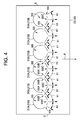
FIG. 4 is a top view of lances of the fluid distribution and mixing grid ofFIG. 2 ; -
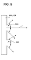
FIG. 5 is a side elevation view of a portion of one of the lances ofFIG. 2 ; -
FIG. 6 is a front elevation view of the fluid distribution and mixing grid ofFIG.2 ; -
FIG. 7A is graph showing oxygen concentration in the recirculated flue gas at one duct diameter downstream of the fluid distribution and mixing grid ofFIG.2 ; -
FIG. 7B is graph showing oxygen concentration in the recirculated flue gas at two duct diameters downstream of the fluid distribution and mixing grid ofFIG.2 ; and -
FIG. 7C is graph showing oxygen concentration in the recirculated flue gas at three duct diameters downstream of the fluid distribution and mixing grid ofFIG.2 . - Referring to
FIG. 1 an oxy-combustion system 100 includes an oxy-combustion furnace 110, for example a tangential fired furnace. The oxy-combustion furnace 110 includes aduct system 112, for example, a windbox positioned at the corners of acombustion portion 114 of the furnace and in communication with aninterior combustion area 115 of the oxy-combustion furnace 110. The oxy-combustion furnace 110 includes anexhaust section 116 positioned downstream of theinterior combustion area 115, for exhausting flue gas from the oxy-combustion furnace 110. The oxy-combustion furnace 110 includes an air pre-heater 120, for example a regenerative air pre-heater positioned downstream of and in communication with theexhaust section 116 via anoutlet duct 118. Theair preheater 120 defines afirst side 120A, for example a flue gas cooling side, separated from a second andthird side combustion furnace 110 includes aparticulate removal system 130, for example an electro-static precipitator or baghouse, positioned downstream of the air pre-heater. Theparticulate removal system 130 is in communication with the air pre-heater 120 via agas duct 128. The oxy-combustion furnace 110 includes asulfur removal system 140, for example a wet or dry flue gas desulfurization system, positioned downstream of and in communication with theparticulate removal system 130 via agas duct 138. The oxy-combustion furnace 110 includes aflue gas cooler 150, for example a counter current water spray heat exchanger, positioned downstream of and in fluid communication with thesulfur removal system 140 via gas duct 148. The oxy-combustion furnace 110 includes agas processing system 160, for example a carbon dioxide removal and sequestration system, positioned downstream of and in fluid communication with theflue gas cooler 150 via agas duct 158. The oxy-combustion furnace 110 includes an air separation unit, for example anoxygen supply system 170 in communication with afuel supply system 180, for example a coal pulverizer and is in communication with the furnace oxy-combustion furnace 110, as described herein. - Referring to
FIG. 1 , the oxy-combustion furnace 110 includes aprimary gas system 200 which provides a mixture of flue gas and oxygen to thefuel supply system 180 for conveying the fuel into theinterior combustion area 115 of the oxy-combustion furnace 110, as described herein. Theprimary gas system 200 includes aprimary transport duct 222 extending from apoint 222A upstream of the fluegas heating side 120B of theair preheater 120, to another point 222AA upstream of the fluegas heating side 120B of theair preheater 120 and to thefuel supply system 180 at apoint 222B. Theprimary transport duct 222 is configured for receiving and transporting a mixture of oxygen and flue gas to thefuel supply system 180, as described herein. - Still, referring to
FIG. 1 , the oxy-combustion furnace 110 includes asecondary gas system 300 which provides a mixture of flue gas and oxygen to the into theinterior combustion area 115 of the oxy-combustion furnace 110, as described herein. Thesecondary gas system 300 includes asecondary transport duct 333 extending from apoint 333A upstream of the fluegas heating side 120B of theair preheater 120 to apoint 333B in thewindbox 112. Thesecondary transport duct 333 is configured for receiving and transporting a mixture of oxygen and flue gas to theinterior combustion area 115, as described herein. - The primary gas system 200 is configured to selectively receive flue gas from the oxy-combustion system 100 via a plurality of points, for example, 1) from a first point 201 located in the outlet duct 118 between the oxy-combustion furnace 110 and the air pre-heater 120, to the primary transport duct 222, via a tie line 210, the secondary transport duct 333 and another tie line 299; 2) from a second point 202 located in the gas duct 128 between the air pre-heater 120 and the particulate removal system 130 to the primary transport duct 222, via a tie line 220, the secondary transport duct 333 and the tie line 299; 3) a third point 203 located in the gas duct 138 between the particulate removal system 130 and the sulfur removal system 140 to the primary transport duct 222, via a tie line 230, the secondary transport duct 333 and the tie line 299; 4) a fourth point 204 located in the gas duct 148 between the sulfur removal system 140 and the flue gas cooler 150 to the primary transport duct 222, via a tie line 240, the secondary transport duct 333 and the tie line 299; and/or 5) a fifth point 205 located in the gas duct 158 between the flue gas cooler 150 and the gas processing system 160 to the primary transport duct 222, via a tie line 150.
- Still referring to
FIG. 1 , theprimary transport duct 222 includes a plurality of injection points, for example afirst injection point 212 located upstream of the fluegas heating side 120B of theair pre-heater 120 and asecond injection point 213 located downstream of the fluegas heating side 120B of theair pre-heater 120. A fluid distribution andmixing grid 500A, for example the fluid distribution andmixing grid 500 shown inFIGS. 2 and6 is positioned in theprimary transport duct 222 at thefirst injection point 212. The fluid distribution andmixing grid 500A is positioned upstream of the fluegas heating side 120B of theair preheater 120. In one embodiment, a fluid distribution andmixing grid 500B, for example the fluid distribution andmixing grid 500 shown inFIGS. 2 and6 is positioned in theprimary transport duct 222 at thesecond injection point 213. The fluid distribution andmixing grid 500B is positioned downstream of the fluegas heating side 120B of theair preheater 120. - The
secondary gas system 300 is configured to selectively receive flue gas from the oxy-combustion system 100 via a plurality of points, for example, 1) from afirst point 201 located in theoutlet duct 118 between the oxy-combustion furnace 110 and theair pre-heater 120 to thesecondary transport duct 333, via thetie line 210; 2) from asecond point 202 located in thegas duct 128 between theair pre-heater 120 and theparticulate removal system 130 to thesecondary transport duct 333, via thetie line 220; 3) athird point 203 located in thegas duct 138 between theparticulate removal system 130 and thesulfur removal system 140 to thesecondary transport duct 333, via thetie line 230; 4) afourth point 204 located in the gas duct 148 between thesulfur removal system 140 and the flue gas cooler 150 to thesecondary transport duct 333, via thetie line 240; and/or 5) afifth point 205 located in thegas duct 158 between the flue gas cooler150 and thegas processing system 160 viatie line 250. - Still referring to
FIG. 1 , thesecondary transport duct 333 includes a plurality of injection ports, for example afirst injection point 301 located upstream of the fluegas heating side 120B of theair pre-heater 120 and asecond injection point 302 located downstream of the fluegas heating side 120B of theair pre-heater 120. A fluid distribution andmixing grid 500C, for example the fluid distribution andmixing grid 500 shown inFIGS. 2 and6 is positioned in thesecondary transport duct 333 at thefirst injection point 301. The fluid distribution andmixing grid 500C is positioned upstream of the fluegas heating side 120B of theair preheater 120. In one embodiment, a fluid distribution andmixing grid 500D, for example the fluid distribution andmixing grid 500 shown inFIGS. 2 and6 is positioned in thesecondary transport duct 333 at thesecond injection point 302. The fluid distribution andmixing grid 500D is positioned downstream of the fluegas heating side 120B of theair preheater 120. - Referring to
FIGS. 2 and6 , the fluid distribution andmixing grid 500 includes a plurality oflances upper lances 510A and sevenbottom lances 510B (FIG. 2 ) or tenupper lances 510A and tenbottom lances 510B (FIG. 6 ), positioned in theprimary transport duct 222 and/or thesecondary transport duct 333. While seven and/or tenupper lances 510A and/orbottom lances 510B are shown and described, the present disclosure is not limited in this regard as any number of lances may be employed and installed in configurations other than upper and lower, including but not limited to lances mounted through sides S of any ducts. - Each of the
upper lances 510A and the bottom lances 510B have a plurality of nozzles formed therein for distribution of a gas, such as, oxygen therefrom, as described below. As shown best inFIG. 2 theprimary transport duct 222 and/or thesecondary transport duct 333 have a square cross section with sides having a length of D and a flow area defined by D2. Although the cross section of theprimary transport duct 222 and/or thesecondary transport duct 333 are shown and described as being square, the present disclosure is not limited in this regard as any suitable geometric cross section including but not limited to rectangular and circular cross sections may be employed. Theupper lances 510A and the bottom lances 510B are arranged in a common plane in the flow area and are substantially parallel to one another. The common plane is generally transverse to, for example perpendicular to, a direction F of flow of flue gas in theprimary transport duct 222 and/or thesecondary transport duct 333. While the common plane is described as being perpendicular to the direction f of flow flue gas, the present disclosure is not limited in this regard as other configurations may be employed, including but not limited to any angle relative to the direction F and in any orientation including horizontal and diagonal. Theupper lances 510A penetrate a top portion T of theprimary transport duct 222 and/or thesecondary transport duct 333. The bottom lances 510B penetrate a bottom portion B of theprimary transport duct 222 and/or thesecondary transport duct 333. Theupper lances 510A define aninlet 511A and aclosed end 512A. The bottom lances 510B define aninlet 511B and aclosed end 512B. The closed ends 512A of the upper lances are spaced apart from the respectiveclosed end 512B of the bottom lances 510B. As shown inFIG. 6 , asleeve 520 is positioned around each adjacent pair of the closed ends 512A and the closed ends 512B, for support purposes. Each pair of the closed ends 510A and the closed ends 501B are moveably positioned in therespective sleeve 520 to allow for thermal expansion and contraction and vibratory movement of theupper lances 510A and the bottom lances 510B. - As shown in
FIG. 6 , two flow control devices, for example acontrol valve 522 and anorifice 524 are positioned upstream of each of theinlets upper lances 510A and the bottom lances 510B. Each of thecontrol valves 522 is in communication with a control system such as manual independent adjustment of thecontrol valves 522 and/or acontroller 525, for example twocontrollers 525 are shown, via aline 526. Thecontrollers 525 are in communication with acomputer processor 528 via aline 527 for, controlling thecontrol valves 522 and the flow of gas to the upper andlower lances control valves 522 for modulating the flow of gas to each of thelances - As shown in
FIGS. 1 and6 , theoxygen supply system 170 is in communication with each of the distribution and mixinggrids 500, (e.g., 500A, 500B, 500C and 500D). As best shown inFIG. 6 , theoxygen supply system 170 is in communication with each of theinlets upper lances 510A and the bottom lances 510B, respectively, via therespective orifices 524 and therespective control valves 522. While theoxygen supply system 170 is shown and described as being in communication with each of theinlets upper lances 510A and the bottom lances 510B, the present disclosure is not limited in this regard as one or more fluids other than or in addition to oxygen may be supplied to one or more of theupper lances 510A and the bottom lances 510B, including but not limited to flue gas, air, water, steam and sorbents. - As shown in
FIGS. 2 and4-6 , each of theupper lances 510A and the bottom lances 510B includes a plurality ofnozzles 555 formed therein. In one embodiment, thenozzles 555 are holes drilled through a surface of theupper lance 510A and the bottom lances 510B. As best shown inFIGS. 4 and5 , there are threenozzles 555 formed in theupper lances 510A and the bottom lances 510B, at each of a plurality of common axial locations. For example, theupper lances 510A and the bottom lances 510B include acentral nozzle 555C aligned coaxially with the direction F of the flue gas flow through theprimary transport duct 222 and/or thesecondary transport duct 333. Theupper lances 510A and the bottom lances 510B include afirst side nozzle 555A and asecond side nozzle 555B positioned on opposing sides of thecentral nozzle 555C and at an angle K1 therefrom. In one embodiment, the angle K1 is about 45 degrees, plus or minus fifteen degrees (i.e., about 30 to 60 degrees). Theupper lances 510A andbottom lances 510B adjacent to the side walls S have one of the side nozzles 555T positioned at an angle K2 from thecentral nozzle 555C and spaced apart therefrom by an angle K2. In one embodiment, the angle K2 is about 22.5 degrees, plus or minus ten degrees (i.e., about 12.5 to about 32.5 degrees). While the groups of three of theside nozzles central nozzle 555C are shown and described as being in a common axial plane, the present disclosure is not limited in this regard as theside nozzles central nozzle 555C as shown for example in two of thelances 510A and two of thelances 510B, inFIG. 6 as referred to by the arrow Q. - The inventors used computational fluid dynamic (CFD) modeling and analysis to determine the quality of the mixing of oxygen and flue gas in ducts using many configurations of one or more static mixing grids modeled in one or more locations (e.g., multiple rows) in various flue duct configurations. While the CFD modeling was performed to quantify the mixing of oxygen in flue gas, the CFD modeling results are also applicable to the mixing of other fluids, gases, liquids, particulate solids and combinations thereof, such as but not limited to SO2, SO3 and mercury.
- After modeling and analyzing CFD results for a significant number of configurations, the inventors surprisingly determined that the
grid 500 demonstrated superior mixing compared to other configurations. For example, the CFD results for thegrid 500 were unexpected because one skilled in the relevant art would have be discouraged from positioning a plurality of thelances grid 500. - Mixing results for the
grid 500 are presented as a coefficient of variation (CoV), which is a measure of the mixed gas homogeneity and equal to the standard deviation divided by the normalized average oxygen concentration at a particular location in the duct. CoV was determined for various lengths downstream of thegrid 500. Length was normalized and presented in terms of diameters of duct, for example the duct equivalent diameters (L/D). A CoV of 0.05 is considered good mixing and 0.02 is considered excellent mixing. The results of the CFD modeling are shown inFIG. 3 , in a graph of CoV versus L/D.FIG. 3 demonstrates that a CoV of 0.05 is reached at point less than one L/D (duct diameter) downstream of thegrid 500; and that a CoV of 0.02 is reached at a point less than four L/D downstream from thegrid 500. In particular, the graph ofFIG. 3 yielded the following data points.Table 1 CoV L/D 0.05 0.75 0.033 1.25 0.028 1.8 0.021 3.2 0.02 3.75 0.018 4.4 0.016 5.0 -
FIGS. 7A, 7B and 7C graphically illustrate and Table 2 summarizes the mixing performance of thegrid 500 obtained from the CFD modeling, at three distances from thegrid 500, namely L/D grid 500 into a flue gas stream. While the CFD modeling is described as being for the mixing of oxygen injected into flue gas, the modeling results also apply to the mixing of other fluids such as gases and liquids into one another, as well as to gasses and fluids having particulate matter entrained therein. - As shown in
FIG. 7A , at a distance L/D of 1 from thegrid 500, there are four corner regions A1-A4 of low oxygen concentration, namely less than 21% (weight percent) oxygen in the flue gas stream and eight central regions A5-A12 of low oxygen concentration, namely less than 21% (weight percent) oxygen concentration. The regions of low oxygen concentration occupy less than 21% of the total flow area of the duct at a plane located at one L/D from thegrid 500. As shown inFIG. 7A , at a distance L/D of 1 from thegrid 500, there are twelve regions (B1-B12) of high oxygen concentration, namely greater than 23.5 % (weight percent) oxygen. The regions of high oxygen concentration occupy less than 22% of the total flow area of the duct at a plane located a one L/D from thegrid 500. The remainder (i.e., greater than 57%) of the gas has an oxygen concentration within the desired target range of 21% to 23.5% (weight percent) oxygen. - As shown in
FIG. 7B , at a distance L/D of 2 from thegrid 500, there are two central regions A1-A2 of low oxygen concentration, namely less than 21% (weight percent) oxygen in the flue gas stream. The regions A1 and A2 of low oxygen concentration occupy less than 10% of the total flow area of the duct at a plane located at two L/D's from thegrid 500. As shown inFIG. 7B , at a distance L/D of 2 from thegrid 500, there are six regions (B1-B6) of high oxygen concentration, namely greater than 23.5 % (weight percent) oxygen. The regions B1-B6 of high oxygen concentration occupy less than 1% of the total flow area of the duct at a plane located a two L/D from thegrid 500. The remainder (i.e., greater than 89%) of the gas has an oxygen concentration within the desired target range of 21% to 23.5% (weight percent) oxygen. - As illustrated in
FIG. 7C , at a distance of three L/D from thegrid 500 greater than 99% e.g., 100% of the gas has an oxygen concentration within the desired target range of 21% to 23.5% (weight percent) oxygen.Table 2 L/D FIG. Low Oxygen Concentration Regions (oxygen concentration less than 21 %) High Oxygen Concentration Regions (oxygen concentration greater than 23.5 %) Target Range of Oxygen Concentration (oxygen concentration in the range of 21 % to 23.5%) Designation Percent of Duct Flow Area Designation Percent of DuctFlow Area Designation Percent of Duct Flow 1 7A Corners-A1, A2, A3 & A4 Central-A5-A12 Less than 21% B1-B12 Less than 22% White background area Remainder, Greater than 57 % 2 7B Central-A1-A2 Less than 10% B1-B6 Less than 1% White background area Remainder, Greater than 89 % 3 7C None 0 % None 0% White background area Greater than 99%, e.g., 100% - While the present invention has been described with reference to various exemplary embodiments, it will be understood by those skilled in the art that various changes may be made and equivalents may be substituted for elements thereof without departing from the scope of the invention. In addition, many modifications may be made to adapt a particular situation or material to the teachings of the invention without departing from the essential scope thereof. Therefore, it is intended that the invention not be limited to the particular embodiment disclosed as the best mode contemplated for carrying out this invention, but that the invention will include all embodiments falling within the scope of the appended claims.
Claims (15)
- An oxy-combustion system (100) comprising:a furnace (110) defining an interior combustion area (115);an oxygen supply system (170);a fuel supply system (180) defining a primary flue gas inlet and a fuel outlet;at least one flue gas processing system (130, 140, 150, 160) positioned downstream of and in communication with the furnace (110);a primary gas system (200) defining a primary flue gas outlet, the primary gas system (200) being in communication with the at least one flue gas processing system (130, 140, 150, 160) and the primary flue gas outlet being in fluid communication with the fuel inlet;a secondary gas system (300) defining a secondary flue gas outlet, the secondary gas system (300) being in communication with the at least one flue gas processing system (130, 140, 150, 160) and the secondary flue gas outlet being in communication with the furnace (110);the at least one oxygen discharge line (529) being in communication with at least one of the primary gas system (200) and the secondary gas system (300); anda grid (500) positioned in a duct (222, 333) of at least one of the primary gas system (200) and the secondary gas system (300), the grid (500) comprising:a plurality of lances (510A, 5120B) arranged in a first plane and positioned transverse to a flow direction (F) of a flue gas outside of the lances (510A, 510B) and within a predetermined flow area;each of the plurality of lances (510A, 510B) having at least one oxygen inlet and a plurality of outlet nozzles, the oxygen inlet being in communication with the oxygen supply system; andat least one of the outlet nozzles (555) being directed generally in the flow direction (F) of the of flue gas outside of the lances (510A, 510B), and configured to discharge oxygen therefrom.
- The oxy-combustion system (100) of claim 1, wherein the primary gas system (200) is in communication with at least one of the furnace (110), an air preheater (120), a particulate removal system (130), a sulfur removal system (140), a flue gas cooler (150) and a carbon dioxide removal system (160).
- The oxy-combustion system (100) of claim 1, wherein the secondary gas system (300) is in communication with at least one of an air preheater (120), a particulate removal system (130), a sulfur removal system (140), a flue gas cooler (150) and a carbon dioxide removal system (160).
- The oxy-combustion system (100) of claim 1, further comprising an air preheater (120) in communication with the primary gas system (200) and the secondary gas system (300), wherein the grid (500) is positioned upstream of the air preheater (120).
- The oxy-combustion system (100) of claim 1, further comprising an air preheater (120) in communication with the primary gas system (200) and the secondary gas system (300), wherein the grid (500) is positioned downstream of the air preheater (120).
- The oxy-combustion system (100) of claim 1, wherein the first plane is positioned substantially perpendicular to the direction (F) of the flue gas flowing outside of the lances (510A, 510B).
- The oxy-combustion system (100) of claim 1, wherein the plurality of lances (510A, 510B) extend vertically in the duct (222, 333).
- The oxy-combustion system (100) of claim 1, wherein the plurality of lances (510A, 510B) extend horizontally in the duct (222, 333).
- The oxy-combustion system (100) of claim 1, wherein the plurality of lances (510A, 510B) includes a set of upper lances (510A) extending downwardly and a set of lower lances (510B) extending upwardly in the duct (222, 333).
- The oxy-combustion system (100) of claim 8, wherein each of the upper lances (510A) vertically align with a respective lower lance (510B), and further comprising at least one sleeve (520) moveable positioned between at least one of the upper lance (510A) and lower lance (510B).
- The oxy-combustion system (100) of claim 1, further comprising at least one flow control device (522, 524) in communication with at least one of the plurality of lances (510A, 510B).
- The oxy-combustion system (100) of claim 11, further comprising a control system (525) in communication with the at least one control device (522, 524) for controlling flow of the oxygen into the at least one of the plurality of lances (510A, 510B).
- The oxy-combustion system (100) of claim 12, wherein the at least one control devices (522, 524) is a valve (522).
- The oxy-combustion system (100) of claim 1, wherein at least one of the plurality of lances (510A, 510B) has at least one of the nozzles (555) positioned at an angle of about 30 to about 60 degrees, relative to the direction (F) of the flue gas flowing outside of the lances (510A, 510B).
- The oxy-combustion system (100) of claim 1, wherein at least one of the plurality of lances (510A, 510B) has at least one of the nozzles (555) positioned at an angle of about 12.5 to about 32.5 degrees, relative to the direction (F) of the flue gas flowing outside of the lances (510A, 510B).
Applications Claiming Priority (2)
| Application Number | Priority Date | Filing Date | Title |
|---|---|---|---|
| US13/751,399 US9518734B2 (en) | 2013-01-28 | 2013-01-28 | Fluid distribution and mixing grid for mixing gases |
| EP14152916.4A EP2759335A3 (en) | 2013-01-28 | 2014-01-28 | Fluid distribution and mixing grid for mixing gases |
Related Parent Applications (1)
| Application Number | Title | Priority Date | Filing Date |
|---|---|---|---|
| EP14152916.4A Division EP2759335A3 (en) | 2013-01-28 | 2014-01-28 | Fluid distribution and mixing grid for mixing gases |
Publications (1)
| Publication Number | Publication Date |
|---|---|
| EP2926891A1 true EP2926891A1 (en) | 2015-10-07 |
Family
ID=50000896
Family Applications (2)
| Application Number | Title | Priority Date | Filing Date |
|---|---|---|---|
| EP15163728.7A Withdrawn EP2926891A1 (en) | 2013-01-28 | 2014-01-28 | Fluid distribution and mixing grid for mixing gases |
| EP14152916.4A Withdrawn EP2759335A3 (en) | 2013-01-28 | 2014-01-28 | Fluid distribution and mixing grid for mixing gases |
Family Applications After (1)
| Application Number | Title | Priority Date | Filing Date |
|---|---|---|---|
| EP14152916.4A Withdrawn EP2759335A3 (en) | 2013-01-28 | 2014-01-28 | Fluid distribution and mixing grid for mixing gases |
Country Status (3)
| Country | Link |
|---|---|
| US (1) | US9518734B2 (en) |
| EP (2) | EP2926891A1 (en) |
| CN (1) | CN103968372B (en) |
Families Citing this family (8)
| Publication number | Priority date | Publication date | Assignee | Title |
|---|---|---|---|---|
| CA2751067C (en) * | 2009-12-11 | 2013-12-03 | Her Majesty The Queen In Right Of Canada As Represented By The Ministeof Natural Resources | Flue gas recirculation method and system for combustion systems |
| US20110143291A1 (en) * | 2009-12-11 | 2011-06-16 | Clements Bruce | Flue gas recirculation method and system for combustion systems |
| US9409124B2 (en) * | 2012-05-22 | 2016-08-09 | Alstom Technology Ltd | Flow control grid |
| US10101090B2 (en) | 2016-07-18 | 2018-10-16 | Owens-Brockway Glass Container Inc. | Duct cleaning and valve device for furnace system |
| CN110404378B (en) * | 2019-07-12 | 2023-07-07 | 华电电力科学研究院有限公司 | Multifunctional flue gas SO 3 Removal test device and working method thereof |
| CN114702971B (en) * | 2022-04-28 | 2024-05-14 | 中冶焦耐(大连)工程技术有限公司 | A coke oven waste gas distribution device and working method thereof |
| US20250027647A1 (en) * | 2023-07-19 | 2025-01-23 | Air Products And Chemicals, Inc. | Apparatus and process for reduced formation of nitrogen oxides during combustion |
| WO2025019011A1 (en) * | 2023-07-19 | 2025-01-23 | Air Products And Chemicals, Inc. | Apparatus and process for oxidant formation |
Citations (8)
| Publication number | Priority date | Publication date | Assignee | Title |
|---|---|---|---|---|
| JPS60132624A (en) * | 1983-12-20 | 1985-07-15 | Babcock Hitachi Kk | Ammonia injection apparatus |
| US5988115A (en) * | 1998-08-11 | 1999-11-23 | Anderson; David K. | SCR reactant injection grid |
| US5997822A (en) * | 1996-08-22 | 1999-12-07 | Hitachi Zosen Corporation | Ammonia injection device for use in exhaust gas denitration systems |
| DE102004052827A1 (en) * | 2004-11-02 | 2006-05-04 | Lurgi Ag | Assembly to generate homogenous gas mixture of o-Xylol and oxidation air for production of pthalic acid anhydride has air laminar flow guide |
| WO2011010160A1 (en) * | 2009-07-23 | 2011-01-27 | Doosan Power Systems Limited | Combustion apparatus |
| CH701602A2 (en) * | 2009-08-13 | 2011-02-15 | Gen Electric | System for injection of cooling air into the exhaust stream of a gas turbine. |
| WO2012042892A1 (en) * | 2010-09-29 | 2012-04-05 | バブコック日立株式会社 | Oxygen combustion system and method for operating same |
| EP2487439A1 (en) * | 2011-02-14 | 2012-08-15 | Alstom Technology Ltd | Method and system for milling a fuel for an oxy-fuel combustion burner |
Family Cites Families (63)
| Publication number | Priority date | Publication date | Assignee | Title |
|---|---|---|---|---|
| DE59204320D1 (en) | 1991-07-30 | 1995-12-21 | Sulzer Chemtech Ag | Mixing device for small amounts of fluid. |
| JP4470346B2 (en) | 2001-01-18 | 2010-06-02 | トヨタ自動車株式会社 | In-vehicle fuel cell system and hydrogen off-gas discharge method |
| EP1448880A1 (en) | 2001-09-24 | 2004-08-25 | ALSTOM Technology Ltd | Gas turbine system for working fluid in the form of a carbon dioxide/water mixture |
| US8246343B2 (en) * | 2003-01-21 | 2012-08-21 | L'air Liquide Societe Anonyme Pour L'etude Et L'exploitation Des Procedes Georges Claude | Device and method for efficient mixing of two streams |
| EP1643100B1 (en) | 2004-09-29 | 2017-06-28 | Ansaldo Energia IP UK Limited | Power plant and associated operating method |
| GB2429937A (en) | 2005-09-08 | 2007-03-14 | Siemens Ind Turbomachinery Ltd | Apparatus for mixing gas streams |
| JP4192930B2 (en) | 2005-09-12 | 2008-12-10 | トヨタ自動車株式会社 | Internal combustion engine |
| SE529333C2 (en) | 2005-11-23 | 2007-07-10 | Norsk Hydro As | The combustion installation |
| US7581948B2 (en) | 2005-12-21 | 2009-09-01 | Johns Manville | Burner apparatus and methods for making inorganic fibers |
| US20070298357A1 (en) | 2006-06-27 | 2007-12-27 | Laux Stefan E F | Oxygen to expand burner combustion capability |
| US20080006188A1 (en) | 2006-07-06 | 2008-01-10 | Kuang Tsai Wu | Increasing boiler output with oxygen |
| US20080034658A1 (en) | 2006-08-14 | 2008-02-14 | Catherine Ann Heiser | Method and Apparatus for the Oxygen-Free Gasification of Hydrocarbonaceous and non-Hydrocarbonaceous Materials for the production of Synthesis gas |
| RU2009110772A (en) | 2006-08-25 | 2010-09-27 | Линде, Инк. (Us) | OXYGEN DISCHARGE THROUGH THE ROOF OR VENT OF A GLASS FUSION FURNACE |
| US7452203B2 (en) | 2006-10-16 | 2008-11-18 | Praxair Technology, Inc. | Stratified staging in kilns |
| US7927568B2 (en) | 2006-10-26 | 2011-04-19 | Foster Wheeler Energy Corporation | Method of and apparatus for CO2 capture in oxy-combustion |
| US8056319B2 (en) | 2006-11-10 | 2011-11-15 | Aerojet—General Corporation | Combined cycle missile engine system |
| SE530875C2 (en) | 2007-02-15 | 2008-09-30 | Scania Cv Ab | Arrangement and procedure of an internal combustion engine |
| US8080090B2 (en) | 2007-02-16 | 2011-12-20 | Air Liquide Process & Construction, Inc. | Process for feed gas cooling in reboiler during CO2 separation |
| US8268050B2 (en) | 2007-02-16 | 2012-09-18 | Air Liquide Process & Construction, Inc. | CO2 separation apparatus and process for oxy-combustion coal power plants |
| US7766999B2 (en) | 2007-02-16 | 2010-08-03 | Air Liquide Process & Construction, Inc. | Process for vaporizing the product CO2 at two different pressures during CO2 separation |
| US20080196583A1 (en) | 2007-02-16 | 2008-08-21 | Bao Ha | Process for recycling of top gas during co2 separtion |
| US8807991B2 (en) | 2007-07-10 | 2014-08-19 | Babcock & Wilcox Power Generation Group, Inc. | Oxy-fuel combustion oxidant heater internal arrangement |
| US8065879B2 (en) | 2007-07-19 | 2011-11-29 | L'air Liquide Societe Anonyme Pour L'etude Et L'exploitation Des Procedes Georges Claude | Thermal integration of oxygen plants |
| DE102007056841A1 (en) | 2007-11-23 | 2009-05-28 | Forschungszentrum Jülich GmbH | Membrane power plant and method of operating such |
| US20090139497A1 (en) | 2007-11-30 | 2009-06-04 | Bo Shi | Engine having thin film oxygen separation system |
| US8453585B2 (en) | 2008-04-14 | 2013-06-04 | Babcock & Wilcox Power Generation Group, Inc. | Oxy-combustion coal fired boiler and method of transitioning between air and oxygen firing |
| US8459213B2 (en) | 2008-04-16 | 2013-06-11 | Donald E. Moriarty | Partially self-refueling low emissions vehicle and stationary power system |
| US8806849B2 (en) | 2008-07-30 | 2014-08-19 | The University Of Wyoming | System and method of operating a power generation system with an alternative working fluid |
| US8316784B2 (en) * | 2008-09-26 | 2012-11-27 | Air Products And Chemicals, Inc. | Oxy/fuel combustion system with minimized flue gas recirculation |
| EP2184105A1 (en) | 2008-11-05 | 2010-05-12 | Süd Chemie - Catalysts Italia S.R.L. | Mixed oxides catalysts |
| US20100126876A1 (en) | 2008-11-24 | 2010-05-27 | Peters Bruce H | Water Purification |
| US20100154429A1 (en) | 2008-11-24 | 2010-06-24 | Peters Bruce H | Water Purification |
| US20110024283A1 (en) | 2008-11-24 | 2011-02-03 | Peters Bruce H | Ammonia Production And Water Purification |
| KR100901120B1 (en) | 2008-12-02 | 2009-06-08 | 황부성 | Hydrogen-oxygen mixed gas combustion burner |
| KR100904884B1 (en) | 2008-12-05 | 2009-06-29 | 황부성 | Hydrogen-oxygen mixed gas combustion burner |
| US20100224477A1 (en) | 2009-03-09 | 2010-09-09 | Peters Bruce H | Water Purification |
| US20110067652A1 (en) | 2009-04-13 | 2011-03-24 | Alan Bishop | Diesel powered semi-trailer truck |
| US20100275777A1 (en) | 2009-04-30 | 2010-11-04 | Hasse David J | Membrane-Based Process for CO2 Capture from Flue Gases Generated by Oxy-Combustion of Coal |
| DE102009021623A1 (en) | 2009-05-16 | 2010-11-25 | Forschungszentrum Jülich GmbH | Power plant and method for operating the same |
| EP2432857A4 (en) | 2009-05-22 | 2015-04-29 | Univ Wyoming | EFFICIENT METHODS AND SYSTEMS FOR GASIFICATION, COMBUSTION, AND TREATMENT OF LOW ROW CHARCOAL |
| US20100314878A1 (en) | 2009-06-16 | 2010-12-16 | Dewitt Monte Douglas | Direct Generation of Steam Motive Flow by Water-Cooled Hydrogen/Oxygen Combustion |
| WO2011001902A1 (en) | 2009-07-01 | 2011-01-06 | 旭硝子株式会社 | Glass melting furnace, process for producing molten glass, apparatus for manufacturing glass products, and process for manufacturing glass products |
| JP5605767B2 (en) | 2009-07-27 | 2014-10-15 | 旭硝子株式会社 | Glass melting furnace, molten glass manufacturing method, glass product manufacturing apparatus, and glass product manufacturing method |
| KR101807320B1 (en) | 2009-08-17 | 2017-12-08 | 아사히 가라스 가부시키가이샤 | Molten glass manufacturing method, glass-melting furnace, glass product manufacturing method, and glass product manufacturing device |
| JP4896195B2 (en) * | 2009-09-30 | 2012-03-14 | 株式会社日立製作所 | Oxyfuel combustion boiler plant and operation method of oxygen combustion boiler plant |
| EP2500642B1 (en) * | 2009-11-09 | 2018-07-11 | IHI Corporation | Oxygen mixing apparatus for oxygen combustion boiler |
| TWI527779B (en) | 2009-11-20 | 2016-04-01 | Asahi Glass Co Ltd | A glass melting furnace, a manufacturing method of a molten glass, a manufacturing apparatus for a glass product, and a method for manufacturing a glass product |
| JP5350996B2 (en) * | 2009-11-25 | 2013-11-27 | バブコック日立株式会社 | Oxygen combustion system exhaust gas treatment equipment |
| US8404909B2 (en) | 2009-12-09 | 2013-03-26 | Chevron U.S.A. Inc. | Method for capturing carbon dioxide from biomass pyrolysis process |
| JP5371831B2 (en) | 2010-02-25 | 2013-12-18 | 三菱電機株式会社 | Manufacturing method of semiconductor device |
| US8550810B2 (en) | 2010-05-28 | 2013-10-08 | Foster Wheeler North America Corp. | Method of controlling a boiler plant during switchover from air-combustion to oxygen-combustion |
| JP5524736B2 (en) | 2010-06-29 | 2014-06-18 | 住友化学株式会社 | Method for producing methionine |
| US9657937B2 (en) | 2010-08-23 | 2017-05-23 | Saudi Arabian Oil Company | Steam generation system having multiple combustion chambers and dry flue gas cleaning |
| US20120070788A1 (en) | 2010-09-20 | 2012-03-22 | Korea Institute Of Energy Research | ECCENTRIC JET TYPE LOW NOx OXYFUEL BURNER |
| JP5427741B2 (en) | 2010-09-21 | 2014-02-26 | 株式会社日立製作所 | Multipurpose thermal power generation system |
| US9388712B2 (en) | 2010-10-13 | 2016-07-12 | Southwest Research Institute | Methods and apparatus for an oxy-fuel based power cycle |
| WO2012064545A2 (en) | 2010-11-10 | 2012-05-18 | Praxair Technology, Inc. | Oxygen enhanced combustion of biomass |
| US20120129112A1 (en) * | 2010-11-22 | 2012-05-24 | Foster Wheeler North America Corp. | Method Of And A System For Combusting Fuel In An Oxyfuel Combustion Boiler |
| US20120129113A1 (en) | 2010-11-22 | 2012-05-24 | Alstom Technology Ltd. | System and method of managing energy utilized in a flue gas processing system |
| DE102010053068A1 (en) | 2010-12-01 | 2012-06-06 | Linde Ag | Method and apparatus for diluted combustion |
| US20120189522A1 (en) | 2011-01-20 | 2012-07-26 | Foster Wheeler North America Corp. | Method of Desulfurizing Flue Gas, an Arrangement for Desulfurizing Flue Gas, and a Method of Modernizing a Desulfurization Arrangement |
| US20120214115A1 (en) | 2011-02-22 | 2012-08-23 | Cameron Andrew M | Method for heating a blast furnace stove |
| US8776761B2 (en) | 2011-11-03 | 2014-07-15 | Seyed Meisam Aledavood | Internal combustion engine with high efficiency |
-
2013
- 2013-01-28 US US13/751,399 patent/US9518734B2/en active Active
-
2014
- 2014-01-27 CN CN201410038875.0A patent/CN103968372B/en active Active
- 2014-01-28 EP EP15163728.7A patent/EP2926891A1/en not_active Withdrawn
- 2014-01-28 EP EP14152916.4A patent/EP2759335A3/en not_active Withdrawn
Patent Citations (8)
| Publication number | Priority date | Publication date | Assignee | Title |
|---|---|---|---|---|
| JPS60132624A (en) * | 1983-12-20 | 1985-07-15 | Babcock Hitachi Kk | Ammonia injection apparatus |
| US5997822A (en) * | 1996-08-22 | 1999-12-07 | Hitachi Zosen Corporation | Ammonia injection device for use in exhaust gas denitration systems |
| US5988115A (en) * | 1998-08-11 | 1999-11-23 | Anderson; David K. | SCR reactant injection grid |
| DE102004052827A1 (en) * | 2004-11-02 | 2006-05-04 | Lurgi Ag | Assembly to generate homogenous gas mixture of o-Xylol and oxidation air for production of pthalic acid anhydride has air laminar flow guide |
| WO2011010160A1 (en) * | 2009-07-23 | 2011-01-27 | Doosan Power Systems Limited | Combustion apparatus |
| CH701602A2 (en) * | 2009-08-13 | 2011-02-15 | Gen Electric | System for injection of cooling air into the exhaust stream of a gas turbine. |
| WO2012042892A1 (en) * | 2010-09-29 | 2012-04-05 | バブコック日立株式会社 | Oxygen combustion system and method for operating same |
| EP2487439A1 (en) * | 2011-02-14 | 2012-08-15 | Alstom Technology Ltd | Method and system for milling a fuel for an oxy-fuel combustion burner |
Also Published As
| Publication number | Publication date |
|---|---|
| US9518734B2 (en) | 2016-12-13 |
| US20140208994A1 (en) | 2014-07-31 |
| CN103968372A (en) | 2014-08-06 |
| CN103968372B (en) | 2018-03-02 |
| EP2759335A2 (en) | 2014-07-30 |
| EP2759335A3 (en) | 2014-10-15 |
Similar Documents
| Publication | Publication Date | Title |
|---|---|---|
| EP2759335A2 (en) | Fluid distribution and mixing grid for mixing gases | |
| EP2996795B1 (en) | Flue gas desulfurization system | |
| US11845037B2 (en) | Systems and methods for removing mercury from emissions | |
| US8375872B2 (en) | Process for reduction of sulfur compounds and nitrogen compounds in the exhaust gases of combustion devices | |
| US9192890B2 (en) | Integrated sorbent injection and flue gas desulfurization system | |
| TWI491435B (en) | Gas mixing arrangement | |
| TWI634940B (en) | Exhaust gas mixing device | |
| TWI544958B (en) | Arrangement for supplying a reducing agent in gaseous form into a flue gas | |
| CN103386251B (en) | There is the injector grid of two-stage blender | |
| TWI633256B (en) | Dual phase fuel feeder, boiler having such a fuel feeder and method for burning solid fuel in such a boiler | |
| CN105107365B (en) | Flue gas composite phase-change dust-removing and desulfurization process and device | |
| GB2569366A (en) | Solid sorbent reactor | |
| CN102179171A (en) | Multi-stage themolysis coupled denitration method using front flow field uniformizing device and device thereof | |
| US8900354B2 (en) | Boosted no-lance injection systems and methods | |
| KR20010076305A (en) | Electrostatic batch preheater | |
| US5685243A (en) | Apparatus for the injection distribution and dispersion of sorbent in a utility boiler furnace | |
| US6510820B1 (en) | Compartmented gas flue for NOx control and particulate removal | |
| JP6063252B2 (en) | Cement plant denitration apparatus and cement plant equipped with the same | |
| CN109621717A (en) | A kind of ammonia-gas spraying device for quick mixed flue gas | |
| CN108889493A (en) | Demercuration adsorbent injection apparatus and coal-fired plant flue gas processing system | |
| US11883776B2 (en) | Systems and methods for removal of mercury and/or hydrochloric acid from gas streams using calcium-containing particles | |
| EP2152388B1 (en) | System for decreasing nox emissions from a fluidized bed combustion system | |
| CN215693178U (en) | SCR denitration reaction tower water conservancy diversion equipartition device of cement kiln | |
| JP7543138B2 (en) | Denitrification catalyst polishing equipment | |
| CN204193783U (en) | A kind of system for stable circulation fluid bed |
Legal Events
| Date | Code | Title | Description |
|---|---|---|---|
| PUAI | Public reference made under article 153(3) epc to a published international application that has entered the european phase |
Free format text: ORIGINAL CODE: 0009012 |
|
| AC | Divisional application: reference to earlier application |
Ref document number: 2759335 Country of ref document: EP Kind code of ref document: P |
|
| AK | Designated contracting states |
Kind code of ref document: A1 Designated state(s): AL AT BE BG CH CY CZ DE DK EE ES FI FR GB GR HR HU IE IS IT LI LT LU LV MC MK MT NL NO PL PT RO RS SE SI SK SM TR |
|
| 17P | Request for examination filed |
Effective date: 20160324 |
|
| RBV | Designated contracting states (corrected) |
Designated state(s): AL AT BE BG CH CY CZ DE DK EE ES FI FR GB GR HR HU IE IS IT LI LT LU LV MC MK MT NL NO PL PT RO RS SE SI SK SM TR |
|
| RAP1 | Party data changed (applicant data changed or rights of an application transferred) |
Owner name: GENERAL ELECTRIC TECHNOLOGY GMBH |
|
| GRAP | Despatch of communication of intention to grant a patent |
Free format text: ORIGINAL CODE: EPIDOSNIGR1 |
|
| INTG | Intention to grant announced |
Effective date: 20170214 |
|
| STAA | Information on the status of an ep patent application or granted ep patent |
Free format text: STATUS: THE APPLICATION IS DEEMED TO BE WITHDRAWN |
|
| 18D | Application deemed to be withdrawn |
Effective date: 20170627 |