EP2926637B1 - Method and apparatus for calibrating a dispenser - Google Patents
Method and apparatus for calibrating a dispenser Download PDFInfo
- Publication number
- EP2926637B1 EP2926637B1 EP13795908.6A EP13795908A EP2926637B1 EP 2926637 B1 EP2926637 B1 EP 2926637B1 EP 13795908 A EP13795908 A EP 13795908A EP 2926637 B1 EP2926637 B1 EP 2926637B1
- Authority
- EP
- European Patent Office
- Prior art keywords
- dispenser
- dispensing
- amount
- dispensed
- controller
- Prior art date
- Legal status (The legal status is an assumption and is not a legal conclusion. Google has not performed a legal analysis and makes no representation as to the accuracy of the status listed.)
- Active
Links
- 238000000034 method Methods 0.000 title claims description 49
- 239000000463 material Substances 0.000 claims description 134
- 239000000758 substrate Substances 0.000 claims description 38
- 238000005303 weighing Methods 0.000 claims description 14
- 238000004140 cleaning Methods 0.000 claims 2
- 239000011345 viscous material Substances 0.000 description 13
- 229910000679 solder Inorganic materials 0.000 description 11
- 230000006870 function Effects 0.000 description 10
- 230000008569 process Effects 0.000 description 8
- 238000013459 approach Methods 0.000 description 5
- 239000007788 liquid Substances 0.000 description 3
- 239000004593 Epoxy Substances 0.000 description 2
- 230000004075 alteration Effects 0.000 description 2
- 238000004891 communication Methods 0.000 description 2
- 230000006872 improvement Effects 0.000 description 2
- 238000005259 measurement Methods 0.000 description 2
- 238000012986 modification Methods 0.000 description 2
- 230000004048 modification Effects 0.000 description 2
- 230000000737 periodic effect Effects 0.000 description 2
- 230000003068 static effect Effects 0.000 description 2
- 238000009736 wetting Methods 0.000 description 2
- 239000000853 adhesive Substances 0.000 description 1
- 230000001070 adhesive effect Effects 0.000 description 1
- 230000008859 change Effects 0.000 description 1
- 238000012512 characterization method Methods 0.000 description 1
- 238000010276 construction Methods 0.000 description 1
- 238000012937 correction Methods 0.000 description 1
- 230000003247 decreasing effect Effects 0.000 description 1
- 238000000151 deposition Methods 0.000 description 1
- 238000010586 diagram Methods 0.000 description 1
- 238000009826 distribution Methods 0.000 description 1
- 238000005516 engineering process Methods 0.000 description 1
- 230000004907 flux Effects 0.000 description 1
- 238000013023 gasketing Methods 0.000 description 1
- 238000010438 heat treatment Methods 0.000 description 1
- 238000003384 imaging method Methods 0.000 description 1
- 230000007246 mechanism Effects 0.000 description 1
- 230000004044 response Effects 0.000 description 1
- 238000007789 sealing Methods 0.000 description 1
- 239000004065 semiconductor Substances 0.000 description 1
- 238000005476 soldering Methods 0.000 description 1
- 238000012546 transfer Methods 0.000 description 1
Images


Classifications
-
- G—PHYSICS
- G01—MEASURING; TESTING
- G01G—WEIGHING
- G01G23/00—Auxiliary devices for weighing apparatus
- G01G23/01—Testing or calibrating of weighing apparatus
-
- H—ELECTRICITY
- H05—ELECTRIC TECHNIQUES NOT OTHERWISE PROVIDED FOR
- H05K—PRINTED CIRCUITS; CASINGS OR CONSTRUCTIONAL DETAILS OF ELECTRIC APPARATUS; MANUFACTURE OF ASSEMBLAGES OF ELECTRICAL COMPONENTS
- H05K13/00—Apparatus or processes specially adapted for manufacturing or adjusting assemblages of electric components
- H05K13/04—Mounting of components, e.g. of leadless components
- H05K13/046—Surface mounting
- H05K13/0469—Surface mounting by applying a glue or viscous material
-
- H—ELECTRICITY
- H05—ELECTRIC TECHNIQUES NOT OTHERWISE PROVIDED FOR
- H05K—PRINTED CIRCUITS; CASINGS OR CONSTRUCTIONAL DETAILS OF ELECTRIC APPARATUS; MANUFACTURE OF ASSEMBLAGES OF ELECTRICAL COMPONENTS
- H05K13/00—Apparatus or processes specially adapted for manufacturing or adjusting assemblages of electric components
- H05K13/08—Monitoring manufacture of assemblages
- H05K13/089—Calibration, teaching or correction of mechanical systems, e.g. of the mounting head
Definitions
- This disclosure relates generally to methods and apparatus for dispensing a viscous material on a substrate, such as a printed circuit board, and more particularly to a method and an apparatus for calibrating or otherwise verifying an amount of material dispensed on a substrate with enhanced efficiency.
- One aspect of the present disclosure is directed to a method of calibrating a dispenser of the type having a material dispensing unit that is configured to dispense material on a substrate.
- the method comprises: providing a weigh scale having a plate configured to receive material dispensed on the plate; dispensing one or more patterns of material on the plate; weighing the amount of material dispensed on the plate; and comparing the weighed amount of material to a designated amount of material.
- the act of dispensing one or more patterns of material replicates at least a portion of patterns of material dispensed on the substrate during a dispensing operation.
- Embodiments of the method further may include adjusting a parameter of the dispenser to vary an amount of material dispensed in the event the weighed amount is outside the predetermined tolerance.
- Adjusting the parameter of the dispenser may include adjusting a speed of the gantry.
- Adjusting the parameter of the dispenser also include adjusting a rotation of an auger screw of the dispensing unit or by adjusting a shot size of the dispensing unit.
- Comparing the weighed amount of material to the designated amount of material may include determining whether the weighed amount of material is within a predetermined tolerance. If the weighed amount of material is outside the predetermined tolerance, the method further may include repeating dispensing, weighing and comparing until the weighed amount is within the predetermined tolerance.
- the method further may include displaying the weight of the pattern dispensed to a user using a user interface device.
- the user interface device may include a display coupled to a dispenser controller.
- the dispensing unit may be an auger-type dispenser. In another embodiment, the dispensing unit may be a jetter-type dispenser.
- controller coupled to a dispenser of the type having a material dispensing unit that is configured to dispense material on a substrate.
- the controller comprises a calibration component configured to perform acts of dispensing one or more patterns of material on a plate of a weigh scale of the dispenser, weighing the amount of material dispensed on the plate, and comparing the weighed amount of material to a designated amount of material.
- the act of dispensing one or more patterns of material replicates at least a portion of patterns of material dispensed on the substrate during a dispensing operation.
- Embodiments of the controller further may include adjusting a parameter of the dispenser to vary an amount of material dispensed in the event the weighed amount is outside the predetermined tolerance. Adjusting the parameter of the dispenser may include adjusting a speed of the gantry. Adjusting the parameter of the dispenser may include adjusting a rotation of an auger screw of the dispensing unit or by adjusting a shot size of the dispensing unit. Comparing the weighed amount of material to the designated amount of material may include determining whether the weighed amount of material is within a predetermined tolerance. If the weighed amount of material is outside the predetermined tolerance, the method further may include repeating dispensing, weighing and comparing until the weighed amount is within the predetermined tolerance.
- the method further may include displaying the weight of the pattern dispensed to a user using a user interface device.
- the user interface device may include a display coupled to the controller.
- the dispensing unit may be an auger-type dispenser. In another embodiment, the dispensing unit may be a jetter-type dispenser.
- Various embodiments of the present disclosure are directed to viscous material dispensing systems, devices including dispensing systems, and methods of determining the amount dispensed by such dispensing systems.
- Such dispensing systems are often used to dispense solder paste, which can be difficult to dispense since the viscosity of the solder paste causes it to adhere a needle of the dispenser when dispensing a small quantity of material for weighing purposes. It has been found that simply weighing a deposited sample in a weigh cup does not accurately measure the amount of material being deposited during a dispensing operation.
- the dispenser is moved over a weigh station to deposit a sample. Once positioned above the weigh station, the dispenser deposits a known quantity into a weigh cup supported on the weigh station.
- This deposited amount is weighed and a controller of the dispenser compares the weighed amount to a predetermined amount stored within the controller. If the weighed amount is not within a predetermined tolerance, the dispenser is adjusted by either slowing the movement of the dispenser as it deposits material on the substrate or by increasing or decreasing the amount dispensed by the dispenser during the dispensing operation.
- the dispenser is static during the calibration sub-routine.
- the static nature of the dispenser causes the material being dispensed, e.g., solder paste, to be impeded while dispensing material during the calibration sub-routine. Material flows more consistently when the dispenser is moving.
- the present disclosure is directed to mimicking the movement of the dispenser during a calibration sub-routine to provide the adhesion experienced between the material and the substrate during a typical dispensing operation. By moving the dispenser during the calibration sub-routine, material flows out of the dispenser more consistently thereby achieving a more accurate deposit of material on the weigh station.
- FIG. 1 schematically illustrates a dispenser, generally indicated at 10, according to one embodiment of the present disclosure.
- the dispenser 10 is used to dispense a viscous material (e.g., solder paste, adhesive, encapsulent, epoxy, underfill material, etc.) or a semi-viscous material (e.g., soldering flux, etc.) onto an electronic substrate 12, such as a printed circuit board or semiconductor wafer.
- a viscous material e.g., solder paste, adhesive, encapsulent, epoxy, underfill material, etc.
- a semi-viscous material e.g., soldering flux, etc.
- the dispenser 10 may alternatively be used in other applications, such as for applying automotive gasketing material or in certain medical applications. It should be understood that references to viscous or semi-viscous materials, as used herein, are exemplary and intended to be non-limiting.
- the dispenser 10 includes at least one dispensing unit or head, generally indicated at 14, an optional dispensing unit or head, generally indicated at 16, and a controller 18 to control the operation of the dispenser. Although two dispensing units are shown, it should be understood that any number of dispensing units may be provided.
- the dispenser 10 may also include a frame 20 having a base 22 for supporting the substrate 12, and a dispensing unit gantry 24 movably coupled to the frame 20 for supporting and moving the dispensing unit 14. The arrangement is that during a dispense operation, the dispensing unit gantry moves the dispensing units over the substrate to dispense material on the substrate.
- the dispenser 10 further includes a weight measurement device or weigh scale (or weigh station) 26 for weighing dispensed quantities of the viscous material, for example, as part of a calibration procedure, and providing weight data to the controller 18.
- the weigh scale 26 includes a plate 27 upon which material is deposited for weighing and for calibrating the accuracy of the dispenser. In one embodiment, the size of the plate is 41 ⁇ 2 centimeters (cm) by 7 cm; however, any sized plate may be provided to receive material for weighing.
- a conveyor system (not shown) or other transfer mechanism such as a walking beam may be used in the dispenser 10 to control loading and unloading of circuit boards to and from the dispenser.
- the gantry 24 can be moved using motors under the control of the controller 18 to position the dispensing unit 14 and/or 16 at predetermined locations over the circuit board.
- the dispenser 10 may optionally include a display unit or display 28 connected to the controller 18 for displaying various information to a user. There may be an optional second controller for controlling the second dispensing unit 16.
- the dispenser Prior to performing a dispensing operation, as described above, the electronic substrate, e.g., printed circuit board, must be aligned or otherwise in registration with the dispensing unit of the dispenser.
- the dispenser further includes a vision system 30, which is coupled to a vision system gantry 32 movably coupled to the frame 20 for supporting and moving the vision system. As described, the vision system 30 is employed to verify the location of landmarks, known as fiducials, on the substrate. Once located, the controller can be programmed to manipulate the movement of the dispensing unit 14 and/or 16 to dispense material on the electronic substrate. The vision system 30 can also be used to inspect boards upon which assembly material is deposited to ensure that the material is deposited on the correct locations.
- Each dispensing unit 14, 16 may be configured to dispense very small amounts or dots onto a circuit board.
- the dispensing unit 14 and/or 16 utilizes a rotating auger having a helical groove to force material out of a nozzle and onto a circuit board.
- a rotating auger having a helical groove to force material out of a nozzle and onto a circuit board.
- U.S. Patent No. 5,819,983 entitled LIQUID DISPENSING SYSTEM WITH SEALING AUGERING SCREW AND METHOD FOR DISPENSING, which is owned by Speedline Technologies, Inc. of Franklin, Massachusetts, a subsidiary of the assignee of the present disclosure.
- the dispenser unit is lowered towards the surface of the circuit board prior to dispensing a dot or a line of material onto the circuit board and raised after dispensing the dot or line of material.
- the dispenser unit is lowered so that the material touches or "wets" the circuit board. The process of wetting contributes to additional time to perform the dispensing operation.
- the dispenser 10 is configured to dispense viscous material using a conventional "streaming" technique, wherein the dispenser launches discrete amounts, or shots, of the material toward the substrate at a controlled volumetric flow rate for each deposit.
- the dispenser 10 may be configured to dispense varying amounts of material in a controllable manner. It is appreciated that the amount of material dispensed in a given configuration of the dispenser 10 may vary with respect to the viscosity of the material being dispensed. For example, materials with a higher viscosity tend to be more resistive to flow than materials with lower viscosity, thus affecting the flow rate of the dispenser 10 in a given configuration and for a given material.
- the viscosity of a particular material may vary over relatively short periods of time (e.g., hours) due to changes in the temperature or other properties of the material, or as a consequence of variations in composition (e.g., between different batches of the material), which further affects the flow rate and, accordingly, the quantity of material deposited per shot. Therefore, according to some aspects, the amount of material dispensed by the dispenser 10 in a given configuration can be determined as a function of the viscosity of the material at the time it is being dispensed. One exemplary function will be described below.
- the dispenser 10 should be calibrated prior to, or during, use to ensure that the desired quantity of material may be dispensed in a predictable manner.
- information gathered during the calibration process may be used, on a periodic or continuous basis, to automatically adjust the dispenser 10 to maintain a desired volumetric flow in response to variations in the viscosity of the material.
- One calibration process includes weighing samples of material dispensed by the dispensing head 14 and/or 16. For example, a series of samples may be dispensed and weighed. An output function can therefore be derived from this sample data that describes the expected output of the dispenser in a given configuration for a given material having a given viscosity. Using the derived output function, a calibrated dispense operation which produces a desired quantity (or weight) of dispensed material may be determined with reasonable accuracy at least for the dispensing head 14 and/or 16 from which the samples were taken.
- the offset can be used to quickly apply calibration adjustments to the dispenser 10. For example, it is known that the viscosity of a material can change over the course of a few hours. Therefore it may be advantageous to recalibrate the dispenser 10 at periodic intervals of operation to help ensure that the actual output is within desired tolerances.
- the output function for each dispensing head may be derived independently. Each dispensing head may be calibrated independently to match a target to within a specified tolerance. Once calibrated, an offset ratio may be calculated to mach outputs of the dispensing heads.
- the configuration procedure enables a user to configure the dispenser 10 to dispense a specific amount of material per shot, and further to enable the dispenser to measure and/or apply corrections, if necessary, such that the output of the dispenser remains substantially the same over a period of time (e.g., one day of operation) to account for any changes in the viscosity (or other property) of the material.
- the configuration procedure enables the user to calibrate a dispenser 10 having two dispensing heads to ensure that the output of both heads is substantially the same.
- the above described characterization process is desirable for ensuring that a consistent volume of material is dispensed for all parts from all of the dispensing machines.
- two or more dispensing machines may be networked together such that all such networked machines can be configured from a single point.
- the computer system may include an operating system that manages at least a portion of the hardware elements included in the computer system.
- a processor or controller executes an operating system which may be, for example, a Windows-based operating system, such as, Windows NT, Windows 2000 (Windows ME), Windows XP or Windows Vista operating systems, available from the Microsoft Corporation, a MAC OS System X operating system available from Apple Computer, one of many Linux-based operating system distributions, for example, the Enterprise Linux operating system available from Red Hat Inc., a Solaris operating system available from Sun Microsystems, or a UNIX operating system available from various sources. Many other operating systems may be used, and the embodiments disclosed herein are not intended to be limited to any particular implementation.
- the processor and operating system together define a computer platform for which application programs in high level programming languages may be written.
- These component applications may be executable, intermediate, for example, C-, bytecode or interpreted code which communicates over a communication network, for example, the Internet, using a communication protocol, for example, TCP/IP.
- aspects in accord with the present disclosure may be implemented using an object-oriented programming language, such as .Net, SmallTalk, Java, C++, Ada, or C# (C-Sharp).
- object-oriented programming languages such as .Net, SmallTalk, Java, C++, Ada, or C# (C-Sharp).
- Other object-oriented programming languages may also be used.
- functional, scripting, or logical programming languages may be used.
- various aspects and functions in accordance with the present disclosure may be implemented in a non-programmed environment, for example, documents created in HTML, XML or other format that, when viewed in a window of a browser program, render aspects of a graphical-user interface or perform other functions.
- various embodiments in accord with the present disclosure may be implemented as programmed or non-programmed elements, or any combination thereof.
- a web page may be implemented using HTML while a data object called from within the web page may be written in C++.
- the disclosure is not limited to a specific programming language and any suitable programming language could also be used.
- Embodiments of the present disclosure performs a calibration sub-routine by mimicking the movement of the dispensing unit 14 and/or 16 during a normal dispensing operation. Specifically, when depositing material on the plate 27 of the weigh scale 26 during a calibration sub-routine, the dispensing unit is moved in a manner similar to the movement of the dispensing unit when dispensing material on the substrate. Based on the weight of the sample of material deposited on the weigh scale 26, a speed of the dispenser gantry may be adjusted to control the amount dispensed. In another embodiment, with an auger-type dispenser, the rotational speed of an auger of the dispensing unit may be adjusted to control the amount dispensed. In yet another embodiment, with a jetter-type dispenser, the shot size of the dispensing unit may be adjusted to control the amount dispensed.
- a method of determining an amount of material, e.g., solder paste, dispensed on a surface by performing a calibration sub-routine is generally indicated at 200. As shown, the method begins at 202. At 204, the dispenser is programmed under the control of the controller to dispense one or more lines or dots of material, e.g., solder paste, on the plate 27 of the weigh scale 26.
- the lines and/or dots of material may be referred to herein as a "pattern" of material since the pattern may include lines (long and short), dots, or both.
- the plate 27 is of a sufficient size so as to enable the dispenser to dispense patterns of material that have been or will be dispensed on a substrate. With large dispense operations, the calibration sub-routine 200 can be shortened so that a portion of the dispensing operation is replicated on the plate or scaled down to a manageable amount.
- the weigh scale 26 measures the weight of the material dispensed on the plate 27, and this information is communicated to the controller 18.
- the controller 18 determines whether the material dispensed is within a predetermined tolerance, which may be preprogrammed within the controller. If the amount of material is within the predetermined tolerance, e.g., within +/- ten percent (10%) of the known weight of material, then the method ends at 212.
- a parameter of the dispenser 10 is adjusted, such as the speed of the gantry, and the process is repeated at 204 until the amount of material is within the predetermined tolerance.
- the rotational speed of the auger screw for an auger-type dispenser may be adjusted or the shot size of the dispenser unit may be adjusted. This process may be repeated any number of times, e.g., five.
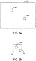
- a substrate 300 is illustrated in FIG. 3A .
- the substrate 300 includes features 302 provided on a surface of the substrate.
- the features 302 are patterns (e.g., lines) of solder paste dispensed on the substrate 300 on which other components may be mounted.
- the features may embody any type of shape or size, including lines, shortened lines, dots, and the like.
- electronic components such as microchips, may be mounted on the substrate by positioning the components on the features and subjecting the substrate to a heat treatment process to mechanically and electrically secure the components to the substrate.
- FIG. 3B illustrates a plate 310 having features 312 deposited on the surface of the plate.
- the plate is a 3.8 cm by 2.5 cm (one inch by one inch) plate having a surface on which material is dispensed.
- the features 312 are identical to the features 302 deposited on the substrate 300.
- the calibration sub-routine discussed above may be performed on the sample deposited on the plate 310 to determine whether the amount of material dispensed on the plate is within a predetermined tolerance.
- the method may further include one or more of the following features:
- Dots of material may be adjusted by changing the rotation of the auger screw for an auger-type dispenser to dispense more or less material while the gantry is stationary.
- the calibration sub-routine may apply to dispensers having auger-type dispensers and jetter-type dispensers, which may be referred to as micro-piston pumps.
- an operator may specify one or more of the following parameters: (1) RPM; (2) z-axis height; (3) for auger-type dispensers the rotation in degrees per millimeter (mm) and for jetter-type dispensers the jetting rate in dots per mm (the "line width" column in a line command); (4) one or more pumps (left and/or right); (5) tolerance; (6) upper and lower limits; (7) measure every n boards or every n minutes; and (8) clean needle before dispensing.
- One or more icon on the display can be provided to assist an operator in performing an operation disclosed herein.
- the length and/or the amount of the dispensed line may not be adjustable by the user but instead may be stored in the database of the controller.
- the pre-dispense plate may be part of the weigh scale or a separate component that is replaceable for positioning different size plates on the weigh scale.
- the dispense location on the plate of the weigh scale may need to be determined in conjunction with any pre-dispense dots and/or pre-dispense line.
- a z-axis sense operation may be executed before dispensing the line. (This may limit the dispense operation to only one pre-dispense plate.)
- the calibration sub-routine may be performed as follows: (1) if the measured value is within the specified tolerance then no changes may occur; (2) if the measured value is outside the specified tolerance then, for example, with auger-type dispensers, a dispensing unit gantry speed may be adjusted or a dispense time and pressure may be adjusted and a new deposit may be dispensed on the plate; (3) continue with step (1) for a maximum of five times; (4) after the fifth attempt an alarm may be posted; and (5) should the result of any measurement be outside the upper or lower limits an alarm may be generated.
- the same handling currently in place for the pre-dispense dots and/or pre-dispense lines may be used.
- results may be stored by the controller in a separate log file.
Description
- This disclosure relates generally to methods and apparatus for dispensing a viscous material on a substrate, such as a printed circuit board, and more particularly to a method and an apparatus for calibrating or otherwise verifying an amount of material dispensed on a substrate with enhanced efficiency.
- There are several types of prior art dispensing systems used for dispensing precise amounts of liquid or paste for a variety of applications. One such application is the assembly of integrated circuit chips and other electronic components onto circuit board substrates. In this application, automated dispensing systems are used for dispensing very small amounts, or dots, of viscous material onto a circuit board. The viscous material may include solder paste or liquid epoxy, or some other related material.
- There are known methods for calibrating a dispensing system to accurately control the rate and amount viscous material that is dispensed from a dispensing unit of the dispensing system. See for example
WO-A1-01/33933 U.S. Patent Application Serial No. 13/072,355, filed on March 25, 2011 , and entitled METHOD AND APPARATUS FOR CALIBRATING DISPENSED DEPOSITS, which is owned by the assignee of the present disclosure. - Another approach is described in
U.S. Patent Application Serial No. 13/598,719, filed on August 30, 2012 - One aspect of the present disclosure is directed to a method of calibrating a dispenser of the type having a material dispensing unit that is configured to dispense material on a substrate. In one embodiment, the method comprises: providing a weigh scale having a plate configured to receive material dispensed on the plate; dispensing one or more patterns of material on the plate; weighing the amount of material dispensed on the plate; and comparing the weighed amount of material to a designated amount of material. The act of dispensing one or more patterns of material replicates at least a portion of patterns of material dispensed on the substrate during a dispensing operation.
- Embodiments of the method further may include adjusting a parameter of the dispenser to vary an amount of material dispensed in the event the weighed amount is outside the predetermined tolerance. Adjusting the parameter of the dispenser may include adjusting a speed of the gantry. Adjusting the parameter of the dispenser also include adjusting a rotation of an auger screw of the dispensing unit or by adjusting a shot size of the dispensing unit. Comparing the weighed amount of material to the designated amount of material may include determining whether the weighed amount of material is within a predetermined tolerance. If the weighed amount of material is outside the predetermined tolerance, the method further may include repeating dispensing, weighing and comparing until the weighed amount is within the predetermined tolerance. The method further may include displaying the weight of the pattern dispensed to a user using a user interface device. The user interface device may include a display coupled to a dispenser controller. In one embodiment, the dispensing unit may be an auger-type dispenser. In another embodiment, the dispensing unit may be a jetter-type dispenser.
- Another aspect of the disclosure is directed to a controller coupled to a dispenser of the type having a material dispensing unit that is configured to dispense material on a substrate. In one embodiment, the controller comprises a calibration component configured to perform acts of dispensing one or more patterns of material on a plate of a weigh scale of the dispenser, weighing the amount of material dispensed on the plate, and comparing the weighed amount of material to a designated amount of material. The act of dispensing one or more patterns of material replicates at least a portion of patterns of material dispensed on the substrate during a dispensing operation.
- Embodiments of the controller further may include adjusting a parameter of the dispenser to vary an amount of material dispensed in the event the weighed amount is outside the predetermined tolerance. Adjusting the parameter of the dispenser may include adjusting a speed of the gantry. Adjusting the parameter of the dispenser may include adjusting a rotation of an auger screw of the dispensing unit or by adjusting a shot size of the dispensing unit. Comparing the weighed amount of material to the designated amount of material may include determining whether the weighed amount of material is within a predetermined tolerance. If the weighed amount of material is outside the predetermined tolerance, the method further may include repeating dispensing, weighing and comparing until the weighed amount is within the predetermined tolerance. The method further may include displaying the weight of the pattern dispensed to a user using a user interface device. The user interface device may include a display coupled to the controller. In one embodiment, the dispensing unit may be an auger-type dispenser. In another embodiment, the dispensing unit may be a jetter-type dispenser.
- The accompanying drawings are not intended to be drawn to scale. In the drawings, each identical or nearly identical component that is illustrated in various figures is represented by a like numeral. For purposes of clarity, not every component may be labeled in every drawing. In the drawings:
-
FIG. 1 is a side schematic view of a dispenser in accordance with one embodiment of the present disclosure; -
FIG. 2 is a schematic block diagram of a method of determining an amount of material dispensed on a substrate; -
FIG. 3A is a top view of a substrate having two features dispensed on the substrate; -
FIG. 3B is a top view of a plate of a weigh scale having two features dispensed on the plate; and -
FIG. 4 is a screen shot of an exemplary user interface. - For the purposes of illustration only, and not to limit the generality, the present disclosure will now be described in detail with reference to the accompanying figures. This disclosure is not limited in its application to the details of construction and the arrangement of components set forth in the following description or illustrated in the drawings. The principles set forth in this disclosure are capable of other embodiments and of being practiced or carried out in various ways. Also the phraseology and terminology used herein is for the purpose of description and should not be regarded as limiting. The use of "including," "comprising," "having," "containing," "involving," and variations thereof herein, is meant to encompass the items listed thereafter and equivalents thereof as well as additional items.
- Various embodiments of the present disclosure are directed to viscous material dispensing systems, devices including dispensing systems, and methods of determining the amount dispensed by such dispensing systems. Such dispensing systems are often used to dispense solder paste, which can be difficult to dispense since the viscosity of the solder paste causes it to adhere a needle of the dispenser when dispensing a small quantity of material for weighing purposes. It has been found that simply weighing a deposited sample in a weigh cup does not accurately measure the amount of material being deposited during a dispensing operation. Specifically, with prior systems and methods, the dispenser is moved over a weigh station to deposit a sample. Once positioned above the weigh station, the dispenser deposits a known quantity into a weigh cup supported on the weigh station. This deposited amount is weighed and a controller of the dispenser compares the weighed amount to a predetermined amount stored within the controller. If the weighed amount is not within a predetermined tolerance, the dispenser is adjusted by either slowing the movement of the dispenser as it deposits material on the substrate or by increasing or decreasing the amount dispensed by the dispenser during the dispensing operation.
- One shortcoming with this known approach is that the dispenser is static during the calibration sub-routine. The static nature of the dispenser causes the material being dispensed, e.g., solder paste, to be impeded while dispensing material during the calibration sub-routine. Material flows more consistently when the dispenser is moving. The present disclosure is directed to mimicking the movement of the dispenser during a calibration sub-routine to provide the adhesion experienced between the material and the substrate during a typical dispensing operation. By moving the dispenser during the calibration sub-routine, material flows out of the dispenser more consistently thereby achieving a more accurate deposit of material on the weigh station.
-
FIG. 1 schematically illustrates a dispenser, generally indicated at 10, according to one embodiment of the present disclosure. Thedispenser 10 is used to dispense a viscous material (e.g., solder paste, adhesive, encapsulent, epoxy, underfill material, etc.) or a semi-viscous material (e.g., soldering flux, etc.) onto anelectronic substrate 12, such as a printed circuit board or semiconductor wafer. Thedispenser 10 may alternatively be used in other applications, such as for applying automotive gasketing material or in certain medical applications. It should be understood that references to viscous or semi-viscous materials, as used herein, are exemplary and intended to be non-limiting. - The
dispenser 10 includes at least one dispensing unit or head, generally indicated at 14, an optional dispensing unit or head, generally indicated at 16, and acontroller 18 to control the operation of the dispenser. Although two dispensing units are shown, it should be understood that any number of dispensing units may be provided. Thedispenser 10 may also include aframe 20 having a base 22 for supporting thesubstrate 12, and a dispensingunit gantry 24 movably coupled to theframe 20 for supporting and moving the dispensingunit 14. The arrangement is that during a dispense operation, the dispensing unit gantry moves the dispensing units over the substrate to dispense material on the substrate. - The
dispenser 10 further includes a weight measurement device or weigh scale (or weigh station) 26 for weighing dispensed quantities of the viscous material, for example, as part of a calibration procedure, and providing weight data to thecontroller 18. Theweigh scale 26 includes aplate 27 upon which material is deposited for weighing and for calibrating the accuracy of the dispenser. In one embodiment, the size of the plate is 4½ centimeters (cm) by 7 cm; however, any sized plate may be provided to receive material for weighing. A conveyor system (not shown) or other transfer mechanism such as a walking beam may be used in thedispenser 10 to control loading and unloading of circuit boards to and from the dispenser. Thegantry 24 can be moved using motors under the control of thecontroller 18 to position the dispensingunit 14 and/or 16 at predetermined locations over the circuit board. Thedispenser 10 may optionally include a display unit ordisplay 28 connected to thecontroller 18 for displaying various information to a user. There may be an optional second controller for controlling thesecond dispensing unit 16. - Prior to performing a dispensing operation, as described above, the electronic substrate, e.g., printed circuit board, must be aligned or otherwise in registration with the dispensing unit of the dispenser. The dispenser further includes a
vision system 30, which is coupled to a vision system gantry 32 movably coupled to theframe 20 for supporting and moving the vision system. As described, thevision system 30 is employed to verify the location of landmarks, known as fiducials, on the substrate. Once located, the controller can be programmed to manipulate the movement of the dispensingunit 14 and/or 16 to dispense material on the electronic substrate. Thevision system 30 can also be used to inspect boards upon which assembly material is deposited to ensure that the material is deposited on the correct locations. - Each dispensing
unit unit 14 and/or 16 utilizes a rotating auger having a helical groove to force material out of a nozzle and onto a circuit board. One such system is disclosed inU.S. Patent No. 5,819,983 , entitled LIQUID DISPENSING SYSTEM WITH SEALING AUGERING SCREW AND METHOD FOR DISPENSING, which is owned by Speedline Technologies, Inc. of Franklin, Massachusetts, a subsidiary of the assignee of the present disclosure. In an operation employing an auger-type dispenser, the dispenser unit is lowered towards the surface of the circuit board prior to dispensing a dot or a line of material onto the circuit board and raised after dispensing the dot or line of material. Using this type of dispenser, small, precise quantities of material may be placed with great accuracy. The time required to lower and raise the dispenser unit in a direction normal to the circuit board, typically known as a z-axis movement, can contribute to the time required to perform dispensing operations. Specifically, with auger-type dispensers, prior to dispensing the dot or line of material, the dispenser unit is lowered so that the material touches or "wets" the circuit board. The process of wetting contributes to additional time to perform the dispensing operation. - It is also known in the field of automated dispensers to launch or jet dots of viscous material toward the circuit board. In such a jetter-type system, a minute, discrete quantity of viscous material is ejected from a nozzle with sufficient momentum to enable the material to separate from the nozzle prior to contacting, or while contacting, the circuit board. As discussed above, with the auger-type application or other prior, traditional dispensers, it is necessary to wet the circuit board with the dot of material prior to releasing the dot from the nozzle. When ejecting, the dots may be deposited on the substrate without wetting as a pattern of discrete dots, or alternatively the dots may be placed sufficiently close to each other to cause them to coalesce into more or less a continuous pattern. One such jetter-type system is disclosed in
U.S. Patent No. 7,980,197 , entitled METHOD AND APPARATUS FOR DISPENSING A VISCOUS MATERIAL ON A SUBSTRATE, which is owned by Illinois Tool Works Inc. of Glenview, Illinois, the assignee of the present disclosure. - In one embodiment, the
dispenser 10 is configured to dispense viscous material using a conventional "streaming" technique, wherein the dispenser launches discrete amounts, or shots, of the material toward the substrate at a controlled volumetric flow rate for each deposit. Thedispenser 10 may be configured to dispense varying amounts of material in a controllable manner. It is appreciated that the amount of material dispensed in a given configuration of thedispenser 10 may vary with respect to the viscosity of the material being dispensed. For example, materials with a higher viscosity tend to be more resistive to flow than materials with lower viscosity, thus affecting the flow rate of thedispenser 10 in a given configuration and for a given material. Further, the viscosity of a particular material may vary over relatively short periods of time (e.g., hours) due to changes in the temperature or other properties of the material, or as a consequence of variations in composition (e.g., between different batches of the material), which further affects the flow rate and, accordingly, the quantity of material deposited per shot. Therefore, according to some aspects, the amount of material dispensed by thedispenser 10 in a given configuration can be determined as a function of the viscosity of the material at the time it is being dispensed. One exemplary function will be described below. - Since it can be important to carefully control the amount of material being dispensed, the
dispenser 10 should be calibrated prior to, or during, use to ensure that the desired quantity of material may be dispensed in a predictable manner. According to one embodiment, information gathered during the calibration process may be used, on a periodic or continuous basis, to automatically adjust thedispenser 10 to maintain a desired volumetric flow in response to variations in the viscosity of the material. - One calibration process includes weighing samples of material dispensed by the dispensing
head 14 and/or 16. For example, a series of samples may be dispensed and weighed. An output function can therefore be derived from this sample data that describes the expected output of the dispenser in a given configuration for a given material having a given viscosity. Using the derived output function, a calibrated dispense operation which produces a desired quantity (or weight) of dispensed material may be determined with reasonable accuracy at least for the dispensinghead 14 and/or 16 from which the samples were taken. - In at least one embodiment, it is appreciated that where two or more dispensing heads, each being substantially identical in configuration, are used to dispense the same or similar material, the output characteristics of one dispensing head relative to another may be substantially similar such that the output functions of each head are nearly identical. In some of these embodiments, any differences between the output functions of the multiple dispensing heads can be accounted for by applying an offset variable to the derived output function of one of the dispensing heads. For example, if the output of a first dispensing head is described by y = f(x), the output of a second dispensing head can be described by y = f(x) + offset with reasonable accuracy, provided that both the first and second heads are dispensing the same material having substantially the same viscosity. The offset can be used to quickly apply calibration adjustments to the
dispenser 10. For example, it is known that the viscosity of a material can change over the course of a few hours. Therefore it may be advantageous to recalibrate thedispenser 10 at periodic intervals of operation to help ensure that the actual output is within desired tolerances. The output function for each dispensing head may be derived independently. Each dispensing head may be calibrated independently to match a target to within a specified tolerance. Once calibrated, an offset ratio may be calculated to mach outputs of the dispensing heads. - One exemplary configuration procedure of the
dispenser 10 will now be described according to various embodiments of the present disclosure. In one embodiment, the configuration procedure enables a user to configure thedispenser 10 to dispense a specific amount of material per shot, and further to enable the dispenser to measure and/or apply corrections, if necessary, such that the output of the dispenser remains substantially the same over a period of time (e.g., one day of operation) to account for any changes in the viscosity (or other property) of the material. In another embodiment, the configuration procedure enables the user to calibrate adispenser 10 having two dispensing heads to ensure that the output of both heads is substantially the same. - According to various embodiments, it is appreciated that in situations where multiple dispensers are performing similar dispensing operations (e.g., in a shop having multiple dispensing machines running at the same time to produce the same parts), the above described characterization process is desirable for ensuring that a consistent volume of material is dispensed for all parts from all of the dispensing machines. In some embodiments, two or more dispensing machines may be networked together such that all such networked machines can be configured from a single point.
- The computer system may include an operating system that manages at least a portion of the hardware elements included in the computer system. Usually, a processor or controller executes an operating system which may be, for example, a Windows-based operating system, such as, Windows NT, Windows 2000 (Windows ME), Windows XP or Windows Vista operating systems, available from the Microsoft Corporation, a MAC OS System X operating system available from Apple Computer, one of many Linux-based operating system distributions, for example, the Enterprise Linux operating system available from Red Hat Inc., a Solaris operating system available from Sun Microsystems, or a UNIX operating system available from various sources. Many other operating systems may be used, and the embodiments disclosed herein are not intended to be limited to any particular implementation.
- The processor and operating system together define a computer platform for which application programs in high level programming languages may be written. These component applications may be executable, intermediate, for example, C-, bytecode or interpreted code which communicates over a communication network, for example, the Internet, using a communication protocol, for example, TCP/IP. Similarly, aspects in accord with the present disclosure may be implemented using an object-oriented programming language, such as .Net, SmallTalk, Java, C++, Ada, or C# (C-Sharp). Other object-oriented programming languages may also be used. Alternatively, functional, scripting, or logical programming languages may be used.
- Additionally, various aspects and functions in accordance with the present disclosure may be implemented in a non-programmed environment, for example, documents created in HTML, XML or other format that, when viewed in a window of a browser program, render aspects of a graphical-user interface or perform other functions. Further, various embodiments in accord with the present disclosure may be implemented as programmed or non-programmed elements, or any combination thereof. For example, a web page may be implemented using HTML while a data object called from within the web page may be written in C++. Thus, the disclosure is not limited to a specific programming language and any suitable programming language could also be used.
- Embodiments of the present disclosure, performs a calibration sub-routine by mimicking the movement of the dispensing
unit 14 and/or 16 during a normal dispensing operation. Specifically, when depositing material on theplate 27 of theweigh scale 26 during a calibration sub-routine, the dispensing unit is moved in a manner similar to the movement of the dispensing unit when dispensing material on the substrate. Based on the weight of the sample of material deposited on theweigh scale 26, a speed of the dispenser gantry may be adjusted to control the amount dispensed. In another embodiment, with an auger-type dispenser, the rotational speed of an auger of the dispensing unit may be adjusted to control the amount dispensed. In yet another embodiment, with a jetter-type dispenser, the shot size of the dispensing unit may be adjusted to control the amount dispensed. - In one embodiment of the present disclosure, and with reference to
FIG. 2 , a method of determining an amount of material, e.g., solder paste, dispensed on a surface by performing a calibration sub-routine is generally indicated at 200. As shown, the method begins at 202. At 204, the dispenser is programmed under the control of the controller to dispense one or more lines or dots of material, e.g., solder paste, on theplate 27 of theweigh scale 26. The lines and/or dots of material may be referred to herein as a "pattern" of material since the pattern may include lines (long and short), dots, or both. Theplate 27 is of a sufficient size so as to enable the dispenser to dispense patterns of material that have been or will be dispensed on a substrate. With large dispense operations, thecalibration sub-routine 200 can be shortened so that a portion of the dispensing operation is replicated on the plate or scaled down to a manageable amount. At 206, theweigh scale 26 measures the weight of the material dispensed on theplate 27, and this information is communicated to thecontroller 18. At 210, thecontroller 18 determines whether the material dispensed is within a predetermined tolerance, which may be preprogrammed within the controller. If the amount of material is within the predetermined tolerance, e.g., within +/- ten percent (10%) of the known weight of material, then the method ends at 212. If the amount of material is not within the predetermined tolerance, a parameter of thedispenser 10 is adjusted, such as the speed of the gantry, and the process is repeated at 204 until the amount of material is within the predetermined tolerance. In another embodiment, the rotational speed of the auger screw for an auger-type dispenser may be adjusted or the shot size of the dispenser unit may be adjusted. This process may be repeated any number of times, e.g., five. - In one example, a
substrate 300 is illustrated inFIG. 3A . As shown, thesubstrate 300 includesfeatures 302 provided on a surface of the substrate. In a certain embodiment, thefeatures 302 are patterns (e.g., lines) of solder paste dispensed on thesubstrate 300 on which other components may be mounted. In other embodiments, as mentioned above, the features may embody any type of shape or size, including lines, shortened lines, dots, and the like. For example, electronic components, such as microchips, may be mounted on the substrate by positioning the components on the features and subjecting the substrate to a heat treatment process to mechanically and electrically secure the components to the substrate. -
FIG. 3B illustrates aplate 310 havingfeatures 312 deposited on the surface of the plate. In one embodiment, the plate is a 3.8 cm by 2.5 cm (one inch by one inch) plate having a surface on which material is dispensed. In the shown example, thefeatures 312 are identical to thefeatures 302 deposited on thesubstrate 300. Thus, the amount of material deposited on theplate 310 should replicate the exact amount of material deposited on thesubstrate 300. The calibration sub-routine discussed above may be performed on the sample deposited on theplate 310 to determine whether the amount of material dispensed on the plate is within a predetermined tolerance. - The method may further include one or more of the following features:
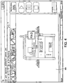
- A dialog box may be provided on the display unit to set up the calibration sub-routine. The dialog box may be generally similar to a weigh block template. The dialog box may apply globally to all lines in the process program. In one embodiment, and with reference to
FIG. 4 , an exemplary dialog box is shown. Specifically,FIG. 4 illustrates auser interface 400 that a user engages to initiate a calibration sub-routine. - Dots of material may be adjusted by changing the rotation of the auger screw for an auger-type dispenser to dispense more or less material while the gantry is stationary.
- The calibration sub-routine may apply to dispensers having auger-type dispensers and jetter-type dispensers, which may be referred to as micro-piston pumps.
- During setup, an operator may specify one or more of the following parameters: (1) RPM; (2) z-axis height; (3) for auger-type dispensers the rotation in degrees per millimeter (mm) and for jetter-type dispensers the jetting rate in dots per mm (the "line width" column in a line command); (4) one or more pumps (left and/or right); (5) tolerance; (6) upper and lower limits; (7) measure every n boards or every n minutes; and (8) clean needle before dispensing. One or more icon on the display can be provided to assist an operator in performing an operation disclosed herein.
- The length and/or the amount of the dispensed line may not be adjustable by the user but instead may be stored in the database of the controller.
- In one embodiment, the pre-dispense plate may be part of the weigh scale or a separate component that is replaceable for positioning different size plates on the weigh scale.
- During execution of the method, in a certain embodiment, the dispense location on the plate of the weigh scale may need to be determined in conjunction with any pre-dispense dots and/or pre-dispense line.
- During execution of the method, in a certain embodiment, a z-axis sense operation may be executed before dispensing the line. (This may limit the dispense operation to only one pre-dispense plate.)
- During execution of the method, in a certain embodiment, the calibration sub-routine may be performed as follows: (1) if the measured value is within the specified tolerance then no changes may occur; (2) if the measured value is outside the specified tolerance then, for example, with auger-type dispensers, a dispensing unit gantry speed may be adjusted or a dispense time and pressure may be adjusted and a new deposit may be dispensed on the plate; (3) continue with step (1) for a maximum of five times; (4) after the fifth attempt an alarm may be posted; and (5) should the result of any measurement be outside the upper or lower limits an alarm may be generated.
- During execution of the method, if the plate is filled then the same handling currently in place for the pre-dispense dots and/or pre-dispense lines may be used.
- Although the embodiment of the method discussed herein performs the method under the control of the controller, an operator of the dispenser can manually initiate a calibration sub-routine operation. In a certain embodiment, results may be stored by the controller in a separate log file.
- Having thus described several aspects of at least one embodiment of this disclosure, it is to be appreciated various alterations, modifications, and improvements will readily occur to those skilled in the art. Such alterations, modifications, and improvements are intended to be part of this disclosure, and are intended to be within the scope of the invention. Accordingly, the foregoing description and drawings are by way of example only.
Claims (14)
- A method of calibrating a dispenser (10) of the type having a material dispensing unit (14, 16) that is configured to dispense material on a substrate (300), the method comprising:providing a weigh scale (26) having a plate (27) configured to receive material dispensed on the plate (27);dispensing one or more patterns (302) of material on the plate (27);weighing the amount of material dispensed on the plate (27); andcomparing the weighed amount of material to a designated amount of material,wherein dispensing one or more patterns (302) of material replicates at least a portion of patterns (302) of material dispensed on the substrate during a dispensing operation,characterized bydisplaying the weight of the pattern (302) dispensed to a user using a user interface device (400) having a display (28) coupled to a dispenser controller (18),wherein during setup the following parameters are specified by an operator: a speed of dispenser gantry (24); a z-axis height of each dispenser (10); for auger-type dispensers a rotation of an auger screw in degrees per millimeter, or for jetter-type dispensers, a jetting rate in dots per millimeter; a predetermined tolerance of the weight of the pattern (302) dispensed; a measure of every n boards or every n minutes; and when to perform a needle cleaning operation; andwherein one or more icons are provided on the display (28) to assist the operator.
- The method of claim 1, wherein comparing the weighed amount of material to the designated amount of material includes determining whether the weighed amount of material is within the predetermined tolerance.
- The method of claim 2, wherein if the weighed amount of material is outside the predetermined tolerance, further comprising repeating dispensing, weighing and comparing until the weighed amount is within the predetermined tolerance.
- The method of claim 2, further comprising adjusting a parameter of the dispenser (10) to vary an amount of material dispensed in the event the weighed amount is outside the predetermined tolerance.
- The method of claim 4, wherein adjusting the parameter of the dispenser (10) includes adjusting the speed of the dispenser gantry (24).
- The method of claim 4, wherein adjusting the parameter of the dispenser (10) includes adjusting the rotation of the auger screw of the dispensing unit (14, 16) or by adjusting a shot size of the dispensing unit (14, 16).
- The method of one of the preceding claims, wherein the dispensing unit (14, 16) is an auger-type dispenser or a jetter-type dispenser.
- A controller (18) coupled to a dispenser (10) of the type having a material dispensing unit (14, 16) that is configured to dispense material on a substrate (300), the controller (18) comprising:a calibration component configured to perform acts of
dispensing one or more patterns (302) of material on a plate (27) of a weigh scale (26) of the dispenser (10),weighing the amount of material dispensed on the plate (27), andcomparing the weighed amount of material to a designated amount of material,wherein dispensing one or more patterns (302) of material replicates at least a portion of patterns (302) of material dispensed on the substrate (300) during a dispensing operation.characterized bysaid calibration component further displaying the weight of the pattern (302) dispensed to a user using a user interface device (400) having a display (28) coupled to a dispenser controller (18),wherein during setup the following parameters are specified by an operator: a speed of dispenser gantry (24); a z-axis height of each dispenser (10); for auger-type dispensers a rotation of an auger screw in degrees per mijlimeter, or for jetter-type dispensers, a jetting rate in dots per millimeter; a predetermined tolerance of the weight of the pattern (302) dispensed; a measure of every n boards or every n minutes; and when to perform a needle cleaning operation; andwherein one or more icons are provided on the display (28) to assist the operator. - The controller of claim 8, wherein comparing the weighed amount of material to the designated amount of material includes determining whether the weighed amount of material is within the predetermined tolerance.
- The controller of claim 9, wherein if the weighed amount of material is outside the predetermined tolerance, further comprising repeating dispensing, weighing and comparing until the weighed amount is within the predetermined tolerance.
- The controller of claim 9, further comprising adjusting a parameter of the dispenser (10) to vary an amount of material dispensed in the event the weighed amount is outside the predetermined tolerance.
- The controller of claim 11, wherein adjusting the parameter of the dispenser (10) includes adjusting the speed of the dispenser gantry (24).
- The controller of claim 12, wherein adjusting the parameter of the dispenser (10) includes adjusting the rotation of the auger screw of the dispensing unit (14, 16) or by adjusting a shot size of the dispensing unit (14, 16).
- The controller of one of claims 8 to 13, wherein the dispensing unit (14, 16) is an auger-type dispenser or a jetter-type dispenser.
Applications Claiming Priority (2)
| Application Number | Priority Date | Filing Date | Title |
|---|---|---|---|
| US13/692,057 US9057642B2 (en) | 2012-12-03 | 2012-12-03 | Method and apparatus for calibrating a dispenser |
| PCT/US2013/068477 WO2014088746A1 (en) | 2012-12-03 | 2013-11-05 | Method and apparatus for calibrating a dispenser |
Publications (2)
| Publication Number | Publication Date |
|---|---|
| EP2926637A1 EP2926637A1 (en) | 2015-10-07 |
| EP2926637B1 true EP2926637B1 (en) | 2017-04-12 |
Family
ID=49667565
Family Applications (1)
| Application Number | Title | Priority Date | Filing Date |
|---|---|---|---|
| EP13795908.6A Active EP2926637B1 (en) | 2012-12-03 | 2013-11-05 | Method and apparatus for calibrating a dispenser |
Country Status (9)
| Country | Link |
|---|---|
| US (1) | US9057642B2 (en) |
| EP (1) | EP2926637B1 (en) |
| JP (1) | JP6215957B2 (en) |
| KR (1) | KR102195227B1 (en) |
| CN (1) | CN104938044B (en) |
| MY (1) | MY183877A (en) |
| PH (1) | PH12015501236B1 (en) |
| SG (1) | SG11201504304PA (en) |
| WO (1) | WO2014088746A1 (en) |
Families Citing this family (6)
| Publication number | Priority date | Publication date | Assignee | Title |
|---|---|---|---|---|
| US20140060144A1 (en) * | 2012-08-30 | 2014-03-06 | Illnois Tool Works Inc. | Method and apparatus for calibrating dispensed deposits |
| US9411779B2 (en) * | 2012-09-28 | 2016-08-09 | Illinois Tool Works Inc. | Method of dispensing material based on edge detection |
| JP2016128152A (en) * | 2015-01-09 | 2016-07-14 | サンユレック株式会社 | Resin body forming method and its formed product |
| WO2017040648A1 (en) * | 2015-08-31 | 2017-03-09 | Nordson Corporation | Automatic piezo stroke adjustment |
| US10434537B2 (en) * | 2017-09-20 | 2019-10-08 | Illinois Tool Works Inc. | Rotation of an array of dispensing pumps to enable simultaneous dispensing with multiple dispensing pumps on multiple electronic substrates |
| CN113188579B (en) * | 2021-02-24 | 2023-03-07 | 常德市计量测试检定所 | Measurement check out test set |
Family Cites Families (47)
| Publication number | Priority date | Publication date | Assignee | Title |
|---|---|---|---|---|
| US5044900A (en) | 1990-03-01 | 1991-09-03 | Knight Tool Company, Inc. | Positive displacement shuttle pump |
| US5320250A (en) * | 1991-12-02 | 1994-06-14 | Asymptotic Technologies, Inc. | Method for rapid dispensing of minute quantities of viscous material |
| US6082289A (en) | 1995-08-24 | 2000-07-04 | Speedline Technologies, Inc. | Liquid dispensing system with controllably movable cartridge |
| US5795390A (en) | 1995-08-24 | 1998-08-18 | Camelot Systems, Inc. | Liquid dispensing system with multiple cartridges |
| US5819983A (en) | 1995-11-22 | 1998-10-13 | Camelot Sysems, Inc. | Liquid dispensing system with sealing augering screw and method for dispensing |
| JP3561353B2 (en) * | 1995-11-29 | 2004-09-02 | 株式会社日立ハイテクインスツルメンツ | Board assembly line management device |
| US5837892A (en) | 1996-10-25 | 1998-11-17 | Camelot Systems, Inc. | Method and apparatus for measuring the size of drops of a viscous material dispensed from a dispensing system |
| US6112588A (en) | 1996-10-25 | 2000-09-05 | Speedline Technologies, Inc. | Method and apparatus for measuring the size of drops of a viscous material dispensed from a dispensing system |
| US6412328B1 (en) | 1996-10-25 | 2002-07-02 | Speedline Technologies, Inc. | Method and apparatus for measuring the size of drops of a viscous material dispensed from a dispensing system |
| US6258165B1 (en) | 1996-11-01 | 2001-07-10 | Speedline Technologies, Inc. | Heater in a conveyor system |
| US5985029A (en) | 1996-11-08 | 1999-11-16 | Speedline Technologies, Inc. | Conveyor system with lifting mechanism |
| US5903125A (en) | 1997-02-06 | 1999-05-11 | Speedline Technologies, Inc. | Positioning system |
| US6056190A (en) | 1997-02-06 | 2000-05-02 | Speedline Technologies, Inc. | Solder ball placement apparatus |
| US6427903B1 (en) | 1997-02-06 | 2002-08-06 | Speedline Technologies, Inc. | Solder ball placement apparatus |
| US6641030B1 (en) | 1997-02-06 | 2003-11-04 | Speedline Technologies, Inc. | Method and apparatus for placing solder balls on a substrate |
| US5886494A (en) | 1997-02-06 | 1999-03-23 | Camelot Systems, Inc. | Positioning system |
| US6093251A (en) | 1997-02-21 | 2000-07-25 | Speedline Technologies, Inc. | Apparatus for measuring the height of a substrate in a dispensing system |
| US5918648A (en) | 1997-02-21 | 1999-07-06 | Speedline Techologies, Inc. | Method and apparatus for measuring volume |
| US5957343A (en) | 1997-06-30 | 1999-09-28 | Speedline Technologies, Inc. | Controllable liquid dispensing device |
| US6085943A (en) | 1997-06-30 | 2000-07-11 | Speedline Technologies, Inc. | Controllable liquid dispensing device |
| US6119895A (en) | 1997-10-10 | 2000-09-19 | Speedline Technologies, Inc. | Method and apparatus for dispensing materials in a vacuum |
| US6007631A (en) | 1997-11-10 | 1999-12-28 | Speedline Technologies, Inc. | Multiple head dispensing system and method |
| US6206964B1 (en) | 1997-11-10 | 2001-03-27 | Speedline Technologies, Inc. | Multiple head dispensing system and method |
| US6214117B1 (en) | 1998-03-02 | 2001-04-10 | Speedline Technologies, Inc. | Dispensing system and method |
| US6866881B2 (en) | 1999-02-19 | 2005-03-15 | Speedline Technologies, Inc. | Dispensing system and method |
| US6216917B1 (en) | 1999-07-13 | 2001-04-17 | Speedline Technologies, Inc. | Dispensing system and method |
| US6541063B1 (en) | 1999-11-04 | 2003-04-01 | Speedline Technologies, Inc. | Calibration of a dispensing system |
| US6514569B1 (en) | 2000-01-14 | 2003-02-04 | Kenneth Crouch | Variable volume positive displacement dispensing system and method |
| US6444035B1 (en) | 2000-01-28 | 2002-09-03 | Speedline Technologies, Inc. | Conveyorized vacuum injection system |
| US6644238B2 (en) | 2000-01-28 | 2003-11-11 | Speedline Technologies, Inc. | Conveyorized vacuum injection system |
| US6688458B2 (en) | 2001-10-09 | 2004-02-10 | Speedline Technologies, Inc. | System and method for controlling a conveyor system configuration to accommodate different size substrates |
| US6775879B2 (en) | 2001-10-10 | 2004-08-17 | Speedline Technologies, Inc. | Needle cleaning system |
| US6932280B2 (en) | 2003-05-02 | 2005-08-23 | Speedline Technologies, Inc. | Adjustable needle foot for dispensing system |
| US20050001869A1 (en) * | 2003-05-23 | 2005-01-06 | Nordson Corporation | Viscous material noncontact jetting system |
| US7404861B2 (en) | 2004-04-23 | 2008-07-29 | Speedline Technologies, Inc. | Imaging and inspection system for a dispenser and method for same |
| US8342636B2 (en) * | 2004-08-23 | 2013-01-01 | Kabushiki Kaisha Ishiihyoki | Discharge rate control method for ink-jet printer, ink spread inspecting method, and oriented film forming method |
| US20060193969A1 (en) | 2005-02-25 | 2006-08-31 | Speedline Technologies, Inc. | Method and apparatus for streaming a viscous material on a substrate |
| US7980197B2 (en) | 2006-11-03 | 2011-07-19 | Illinois Tool Works, Inc. | Method and apparatus for dispensing a viscous material on a substrate |
| US7833572B2 (en) | 2007-06-01 | 2010-11-16 | Illinois Tool Works, Inc. | Method and apparatus for dispensing a viscous material on a substrate |
| US7923056B2 (en) * | 2007-06-01 | 2011-04-12 | Illinois Tool Works Inc. | Method and apparatus for dispensing material on a substrate |
| US8136705B2 (en) | 2009-04-09 | 2012-03-20 | Illinois Tool Works Inc. | Magnetic drive for dispensing apparatus |
| US8714716B2 (en) | 2010-08-25 | 2014-05-06 | Illinois Tool Works Inc. | Pulsed air-actuated micro-droplet on demand ink jet |
| US8733244B2 (en) * | 2010-12-08 | 2014-05-27 | Illinois Tool Works, Inc. | Methods for depositing viscous material on a substrate with a combination stencil printer and dispenser |
| JP5779353B2 (en) | 2011-01-19 | 2015-09-16 | 武蔵エンジニアリング株式会社 | Liquid material coating method, coating apparatus and program |
| US8616042B2 (en) * | 2011-03-25 | 2013-12-31 | Illinois Tool Works Inc. | Method and apparatus for calibrating dispensed deposits |
| US20130133574A1 (en) | 2011-11-29 | 2013-05-30 | Illinois Tool Works Inc. | Material deposition system for depositing materials on a substrate |
| US20130136850A1 (en) | 2011-11-29 | 2013-05-30 | Illinois Tool Works Inc. | Method for depositing materials on a substrate |
-
2012
- 2012-12-03 US US13/692,057 patent/US9057642B2/en active Active
-
2013
- 2013-11-05 KR KR1020157017514A patent/KR102195227B1/en active IP Right Grant
- 2013-11-05 JP JP2015546480A patent/JP6215957B2/en active Active
- 2013-11-05 EP EP13795908.6A patent/EP2926637B1/en active Active
- 2013-11-05 MY MYPI2015701781A patent/MY183877A/en unknown
- 2013-11-05 WO PCT/US2013/068477 patent/WO2014088746A1/en active Application Filing
- 2013-11-05 CN CN201380071124.2A patent/CN104938044B/en active Active
- 2013-11-05 SG SG11201504304PA patent/SG11201504304PA/en unknown
-
2015
- 2015-06-02 PH PH12015501236A patent/PH12015501236B1/en unknown
Non-Patent Citations (1)
| Title |
|---|
| None * |
Also Published As
| Publication number | Publication date |
|---|---|
| CN104938044B (en) | 2018-06-01 |
| PH12015501236A1 (en) | 2015-08-17 |
| WO2014088746A1 (en) | 2014-06-12 |
| EP2926637A1 (en) | 2015-10-07 |
| JP6215957B2 (en) | 2017-10-18 |
| PH12015501236B1 (en) | 2015-08-17 |
| SG11201504304PA (en) | 2015-06-29 |
| JP2016502672A (en) | 2016-01-28 |
| US20140150518A1 (en) | 2014-06-05 |
| KR20150092235A (en) | 2015-08-12 |
| US9057642B2 (en) | 2015-06-16 |
| KR102195227B1 (en) | 2020-12-24 |
| CN104938044A (en) | 2015-09-23 |
| MY183877A (en) | 2021-03-17 |
Similar Documents
| Publication | Publication Date | Title |
|---|---|---|
| EP2926637B1 (en) | Method and apparatus for calibrating a dispenser | |
| EP2688685B1 (en) | Method and apparatus for calibrating dispensed deposits | |
| WO2014036185A1 (en) | Method and apparatus for calibrating dispensed deposits | |
| JP6626153B2 (en) | Automated multiple head cleaner and related method of dispensing system | |
| US10926287B2 (en) | Method of calibrating a dispenser | |
| EP2901827A2 (en) | Dispensing system and method of dispensing material based on angular locate feature | |
| CN104275277A (en) | Method for coating and adjusting viscous material | |
| JPH10202161A (en) | Method and device for precisely coating liquid by robot | |
| CN111108822B (en) | Method and system for dispensing material simultaneously on multiple electronic substrates |
Legal Events
| Date | Code | Title | Description |
|---|---|---|---|
| PUAI | Public reference made under article 153(3) epc to a published international application that has entered the european phase |
Free format text: ORIGINAL CODE: 0009012 |
|
| 17P | Request for examination filed |
Effective date: 20150610 |
|
| AK | Designated contracting states |
Kind code of ref document: A1 Designated state(s): AL AT BE BG CH CY CZ DE DK EE ES FI FR GB GR HR HU IE IS IT LI LT LU LV MC MK MT NL NO PL PT RO RS SE SI SK SM TR |
|
| AX | Request for extension of the european patent |
Extension state: BA ME |
|
| DAX | Request for extension of the european patent (deleted) | ||
| GRAP | Despatch of communication of intention to grant a patent |
Free format text: ORIGINAL CODE: EPIDOSNIGR1 |
|
| INTG | Intention to grant announced |
Effective date: 20161216 |
|
| RIN1 | Information on inventor provided before grant (corrected) |
Inventor name: SHULTZ, TRACI, ANNE Inventor name: KARLINSKI, THOMAS, J. Inventor name: BLOOM, JONATHAN JOEL |
|
| GRAS | Grant fee paid |
Free format text: ORIGINAL CODE: EPIDOSNIGR3 |
|
| GRAA | (expected) grant |
Free format text: ORIGINAL CODE: 0009210 |
|
| AK | Designated contracting states |
Kind code of ref document: B1 Designated state(s): AL AT BE BG CH CY CZ DE DK EE ES FI FR GB GR HR HU IE IS IT LI LT LU LV MC MK MT NL NO PL PT RO RS SE SI SK SM TR |
|
| REG | Reference to a national code |
Ref country code: GB Ref legal event code: FG4D |
|
| REG | Reference to a national code |
Ref country code: CH Ref legal event code: EP |
|
| REG | Reference to a national code |
Ref country code: IE Ref legal event code: FG4D |
|
| REG | Reference to a national code |
Ref country code: AT Ref legal event code: REF Ref document number: 884986 Country of ref document: AT Kind code of ref document: T Effective date: 20170515 |
|
| REG | Reference to a national code |
Ref country code: DE Ref legal event code: R096 Ref document number: 602013019826 Country of ref document: DE |
|
| REG | Reference to a national code |
Ref country code: NL Ref legal event code: MP Effective date: 20170412 |
|
| REG | Reference to a national code |
Ref country code: LT Ref legal event code: MG4D |
|
| REG | Reference to a national code |
Ref country code: AT Ref legal event code: MK05 Ref document number: 884986 Country of ref document: AT Kind code of ref document: T Effective date: 20170412 |
|
| PG25 | Lapsed in a contracting state [announced via postgrant information from national office to epo] |
Ref country code: NL Free format text: LAPSE BECAUSE OF FAILURE TO SUBMIT A TRANSLATION OF THE DESCRIPTION OR TO PAY THE FEE WITHIN THE PRESCRIBED TIME-LIMIT Effective date: 20170412 |
|
| PG25 | Lapsed in a contracting state [announced via postgrant information from national office to epo] |
Ref country code: LT Free format text: LAPSE BECAUSE OF FAILURE TO SUBMIT A TRANSLATION OF THE DESCRIPTION OR TO PAY THE FEE WITHIN THE PRESCRIBED TIME-LIMIT Effective date: 20170412 Ref country code: GR Free format text: LAPSE BECAUSE OF FAILURE TO SUBMIT A TRANSLATION OF THE DESCRIPTION OR TO PAY THE FEE WITHIN THE PRESCRIBED TIME-LIMIT Effective date: 20170713 Ref country code: FI Free format text: LAPSE BECAUSE OF FAILURE TO SUBMIT A TRANSLATION OF THE DESCRIPTION OR TO PAY THE FEE WITHIN THE PRESCRIBED TIME-LIMIT Effective date: 20170412 Ref country code: HR Free format text: LAPSE BECAUSE OF FAILURE TO SUBMIT A TRANSLATION OF THE DESCRIPTION OR TO PAY THE FEE WITHIN THE PRESCRIBED TIME-LIMIT Effective date: 20170412 Ref country code: AT Free format text: LAPSE BECAUSE OF FAILURE TO SUBMIT A TRANSLATION OF THE DESCRIPTION OR TO PAY THE FEE WITHIN THE PRESCRIBED TIME-LIMIT Effective date: 20170412 Ref country code: NO Free format text: LAPSE BECAUSE OF FAILURE TO SUBMIT A TRANSLATION OF THE DESCRIPTION OR TO PAY THE FEE WITHIN THE PRESCRIBED TIME-LIMIT Effective date: 20170712 Ref country code: ES Free format text: LAPSE BECAUSE OF FAILURE TO SUBMIT A TRANSLATION OF THE DESCRIPTION OR TO PAY THE FEE WITHIN THE PRESCRIBED TIME-LIMIT Effective date: 20170412 |
|
| PG25 | Lapsed in a contracting state [announced via postgrant information from national office to epo] |
Ref country code: IS Free format text: LAPSE BECAUSE OF FAILURE TO SUBMIT A TRANSLATION OF THE DESCRIPTION OR TO PAY THE FEE WITHIN THE PRESCRIBED TIME-LIMIT Effective date: 20170812 Ref country code: LV Free format text: LAPSE BECAUSE OF FAILURE TO SUBMIT A TRANSLATION OF THE DESCRIPTION OR TO PAY THE FEE WITHIN THE PRESCRIBED TIME-LIMIT Effective date: 20170412 Ref country code: PL Free format text: LAPSE BECAUSE OF FAILURE TO SUBMIT A TRANSLATION OF THE DESCRIPTION OR TO PAY THE FEE WITHIN THE PRESCRIBED TIME-LIMIT Effective date: 20170412 Ref country code: RS Free format text: LAPSE BECAUSE OF FAILURE TO SUBMIT A TRANSLATION OF THE DESCRIPTION OR TO PAY THE FEE WITHIN THE PRESCRIBED TIME-LIMIT Effective date: 20170412 Ref country code: BG Free format text: LAPSE BECAUSE OF FAILURE TO SUBMIT A TRANSLATION OF THE DESCRIPTION OR TO PAY THE FEE WITHIN THE PRESCRIBED TIME-LIMIT Effective date: 20170712 Ref country code: SE Free format text: LAPSE BECAUSE OF FAILURE TO SUBMIT A TRANSLATION OF THE DESCRIPTION OR TO PAY THE FEE WITHIN THE PRESCRIBED TIME-LIMIT Effective date: 20170412 |
|
| REG | Reference to a national code |
Ref country code: DE Ref legal event code: R097 Ref document number: 602013019826 Country of ref document: DE |
|
| PG25 | Lapsed in a contracting state [announced via postgrant information from national office to epo] |
Ref country code: DK Free format text: LAPSE BECAUSE OF FAILURE TO SUBMIT A TRANSLATION OF THE DESCRIPTION OR TO PAY THE FEE WITHIN THE PRESCRIBED TIME-LIMIT Effective date: 20170412 Ref country code: EE Free format text: LAPSE BECAUSE OF FAILURE TO SUBMIT A TRANSLATION OF THE DESCRIPTION OR TO PAY THE FEE WITHIN THE PRESCRIBED TIME-LIMIT Effective date: 20170412 Ref country code: SK Free format text: LAPSE BECAUSE OF FAILURE TO SUBMIT A TRANSLATION OF THE DESCRIPTION OR TO PAY THE FEE WITHIN THE PRESCRIBED TIME-LIMIT Effective date: 20170412 Ref country code: RO Free format text: LAPSE BECAUSE OF FAILURE TO SUBMIT A TRANSLATION OF THE DESCRIPTION OR TO PAY THE FEE WITHIN THE PRESCRIBED TIME-LIMIT Effective date: 20170412 Ref country code: CZ Free format text: LAPSE BECAUSE OF FAILURE TO SUBMIT A TRANSLATION OF THE DESCRIPTION OR TO PAY THE FEE WITHIN THE PRESCRIBED TIME-LIMIT Effective date: 20170412 |
|
| PLBE | No opposition filed within time limit |
Free format text: ORIGINAL CODE: 0009261 |
|
| STAA | Information on the status of an ep patent application or granted ep patent |
Free format text: STATUS: NO OPPOSITION FILED WITHIN TIME LIMIT |
|
| PG25 | Lapsed in a contracting state [announced via postgrant information from national office to epo] |
Ref country code: IT Free format text: LAPSE BECAUSE OF FAILURE TO SUBMIT A TRANSLATION OF THE DESCRIPTION OR TO PAY THE FEE WITHIN THE PRESCRIBED TIME-LIMIT Effective date: 20170412 Ref country code: SM Free format text: LAPSE BECAUSE OF FAILURE TO SUBMIT A TRANSLATION OF THE DESCRIPTION OR TO PAY THE FEE WITHIN THE PRESCRIBED TIME-LIMIT Effective date: 20170412 |
|
| 26N | No opposition filed |
Effective date: 20180115 |
|
| PG25 | Lapsed in a contracting state [announced via postgrant information from national office to epo] |
Ref country code: SI Free format text: LAPSE BECAUSE OF FAILURE TO SUBMIT A TRANSLATION OF THE DESCRIPTION OR TO PAY THE FEE WITHIN THE PRESCRIBED TIME-LIMIT Effective date: 20170412 |
|
| PG25 | Lapsed in a contracting state [announced via postgrant information from national office to epo] |
Ref country code: MC Free format text: LAPSE BECAUSE OF FAILURE TO SUBMIT A TRANSLATION OF THE DESCRIPTION OR TO PAY THE FEE WITHIN THE PRESCRIBED TIME-LIMIT Effective date: 20170412 |
|
| PG25 | Lapsed in a contracting state [announced via postgrant information from national office to epo] |
Ref country code: CH Free format text: LAPSE BECAUSE OF NON-PAYMENT OF DUE FEES Effective date: 20171130 Ref country code: LI Free format text: LAPSE BECAUSE OF NON-PAYMENT OF DUE FEES Effective date: 20171130 |
|
| PG25 | Lapsed in a contracting state [announced via postgrant information from national office to epo] |
Ref country code: LU Free format text: LAPSE BECAUSE OF NON-PAYMENT OF DUE FEES Effective date: 20171105 |
|
| REG | Reference to a national code |
Ref country code: FR Ref legal event code: ST Effective date: 20180731 Ref country code: BE Ref legal event code: MM Effective date: 20171130 |
|
| REG | Reference to a national code |
Ref country code: IE Ref legal event code: MM4A |
|
| PG25 | Lapsed in a contracting state [announced via postgrant information from national office to epo] |
Ref country code: MT Free format text: LAPSE BECAUSE OF NON-PAYMENT OF DUE FEES Effective date: 20171105 |
|
| PG25 | Lapsed in a contracting state [announced via postgrant information from national office to epo] |
Ref country code: IE Free format text: LAPSE BECAUSE OF NON-PAYMENT OF DUE FEES Effective date: 20171105 Ref country code: FR Free format text: LAPSE BECAUSE OF NON-PAYMENT OF DUE FEES Effective date: 20171130 |
|
| PG25 | Lapsed in a contracting state [announced via postgrant information from national office to epo] |
Ref country code: BE Free format text: LAPSE BECAUSE OF NON-PAYMENT OF DUE FEES Effective date: 20171130 |
|
| PG25 | Lapsed in a contracting state [announced via postgrant information from national office to epo] |
Ref country code: HU Free format text: LAPSE BECAUSE OF FAILURE TO SUBMIT A TRANSLATION OF THE DESCRIPTION OR TO PAY THE FEE WITHIN THE PRESCRIBED TIME-LIMIT; INVALID AB INITIO Effective date: 20131105 |
|
| PG25 | Lapsed in a contracting state [announced via postgrant information from national office to epo] |
Ref country code: CY Free format text: LAPSE BECAUSE OF FAILURE TO SUBMIT A TRANSLATION OF THE DESCRIPTION OR TO PAY THE FEE WITHIN THE PRESCRIBED TIME-LIMIT Effective date: 20170412 |
|
| PG25 | Lapsed in a contracting state [announced via postgrant information from national office to epo] |
Ref country code: MK Free format text: LAPSE BECAUSE OF FAILURE TO SUBMIT A TRANSLATION OF THE DESCRIPTION OR TO PAY THE FEE WITHIN THE PRESCRIBED TIME-LIMIT Effective date: 20170412 |
|
| PG25 | Lapsed in a contracting state [announced via postgrant information from national office to epo] |
Ref country code: TR Free format text: LAPSE BECAUSE OF FAILURE TO SUBMIT A TRANSLATION OF THE DESCRIPTION OR TO PAY THE FEE WITHIN THE PRESCRIBED TIME-LIMIT Effective date: 20170412 |
|
| PG25 | Lapsed in a contracting state [announced via postgrant information from national office to epo] |
Ref country code: PT Free format text: LAPSE BECAUSE OF FAILURE TO SUBMIT A TRANSLATION OF THE DESCRIPTION OR TO PAY THE FEE WITHIN THE PRESCRIBED TIME-LIMIT Effective date: 20170412 |
|
| PG25 | Lapsed in a contracting state [announced via postgrant information from national office to epo] |
Ref country code: AL Free format text: LAPSE BECAUSE OF FAILURE TO SUBMIT A TRANSLATION OF THE DESCRIPTION OR TO PAY THE FEE WITHIN THE PRESCRIBED TIME-LIMIT Effective date: 20170412 |
|
| P01 | Opt-out of the competence of the unified patent court (upc) registered |
Effective date: 20230606 |
|
| PGFP | Annual fee paid to national office [announced via postgrant information from national office to epo] |
Ref country code: GB Payment date: 20231127 Year of fee payment: 11 |
|
| PGFP | Annual fee paid to national office [announced via postgrant information from national office to epo] |
Ref country code: DE Payment date: 20231129 Year of fee payment: 11 |