EP2926606B1 - Systems and methods for optimization of synchronization message transmission intervals in a peer-to-peer network - Google Patents
Systems and methods for optimization of synchronization message transmission intervals in a peer-to-peer network Download PDFInfo
- Publication number
- EP2926606B1 EP2926606B1 EP13798523.0A EP13798523A EP2926606B1 EP 2926606 B1 EP2926606 B1 EP 2926606B1 EP 13798523 A EP13798523 A EP 13798523A EP 2926606 B1 EP2926606 B1 EP 2926606B1
- Authority
- EP
- European Patent Office
- Prior art keywords
- clock drift
- network
- wireless device
- drift
- information
- Prior art date
- Legal status (The legal status is an assumption and is not a legal conclusion. Google has not performed a legal analysis and makes no representation as to the accuracy of the status listed.)
- Not-in-force
Links
- 238000000034 method Methods 0.000 title claims description 72
- 230000005540 biological transmission Effects 0.000 title description 12
- 238000005457 optimization Methods 0.000 title description 2
- 238000004891 communication Methods 0.000 claims description 71
- 238000004590 computer program Methods 0.000 claims description 4
- 238000005259 measurement Methods 0.000 claims description 3
- 230000006870 function Effects 0.000 description 12
- 230000006855 networking Effects 0.000 description 7
- 238000012545 processing Methods 0.000 description 7
- 230000003287 optical effect Effects 0.000 description 6
- 230000008569 process Effects 0.000 description 6
- 230000009286 beneficial effect Effects 0.000 description 5
- DNBCBAXDWNDRNO-FOSCPWQOSA-N (3aS,6aR)-N-(3-methoxy-1,2,4-thiadiazol-5-yl)-5-[methyl(7H-pyrrolo[2,3-d]pyrimidin-4-yl)amino]-3,3a,4,5,6,6a-hexahydro-1H-cyclopenta[c]pyrrole-2-carboxamide Chemical compound COC1=NSC(NC(=O)N2C[C@H]3CC(C[C@H]3C2)N(C)C=2C=3C=CNC=3N=CN=2)=N1 DNBCBAXDWNDRNO-FOSCPWQOSA-N 0.000 description 4
- BVGDAZBTIVRTGO-UONOGXRCSA-N 3-[(1r)-1-(2,6-dichloro-3-fluorophenyl)ethoxy]-5-[4-methoxy-6-[(2s)-2-methylpiperazin-1-yl]pyridin-3-yl]pyridin-2-amine Chemical compound C1([C@@H](C)OC=2C(N)=NC=C(C=2)C2=CN=C(C=C2OC)N2[C@H](CNCC2)C)=C(Cl)C=CC(F)=C1Cl BVGDAZBTIVRTGO-UONOGXRCSA-N 0.000 description 4
- 238000013461 design Methods 0.000 description 4
- UXHQLGLGLZKHTC-CUNXSJBXSA-N 4-[(3s,3ar)-3-cyclopentyl-7-(4-hydroxypiperidine-1-carbonyl)-3,3a,4,5-tetrahydropyrazolo[3,4-f]quinolin-2-yl]-2-chlorobenzonitrile Chemical compound C1CC(O)CCN1C(=O)C1=CC=C(C=2[C@@H]([C@H](C3CCCC3)N(N=2)C=2C=C(Cl)C(C#N)=CC=2)CC2)C2=N1 UXHQLGLGLZKHTC-CUNXSJBXSA-N 0.000 description 3
- ONPGOSVDVDPBCY-CQSZACIVSA-N 6-amino-5-[(1r)-1-(2,6-dichloro-3-fluorophenyl)ethoxy]-n-[4-(4-methylpiperazine-1-carbonyl)phenyl]pyridazine-3-carboxamide Chemical compound O([C@H](C)C=1C(=C(F)C=CC=1Cl)Cl)C(C(=NN=1)N)=CC=1C(=O)NC(C=C1)=CC=C1C(=O)N1CCN(C)CC1 ONPGOSVDVDPBCY-CQSZACIVSA-N 0.000 description 3
- 230000008901 benefit Effects 0.000 description 3
- 238000004422 calculation algorithm Methods 0.000 description 3
- 238000004364 calculation method Methods 0.000 description 3
- 230000001413 cellular effect Effects 0.000 description 3
- 230000008859 change Effects 0.000 description 3
- 230000000694 effects Effects 0.000 description 3
- 238000005516 engineering process Methods 0.000 description 3
- 230000007246 mechanism Effects 0.000 description 3
- AYOOGWWGECJQPI-NSHDSACASA-N n-[(1s)-1-(5-fluoropyrimidin-2-yl)ethyl]-3-(3-propan-2-yloxy-1h-pyrazol-5-yl)imidazo[4,5-b]pyridin-5-amine Chemical compound N1C(OC(C)C)=CC(N2C3=NC(N[C@@H](C)C=4N=CC(F)=CN=4)=CC=C3N=C2)=N1 AYOOGWWGECJQPI-NSHDSACASA-N 0.000 description 3
- KJUCPVIVNLPLEE-UHFFFAOYSA-N 2,6-difluoro-n-[2-fluoro-5-[5-[2-[(6-morpholin-4-ylpyridin-3-yl)amino]pyrimidin-4-yl]-2-propan-2-yl-1,3-thiazol-4-yl]phenyl]benzenesulfonamide Chemical compound S1C(C(C)C)=NC(C=2C=C(NS(=O)(=O)C=3C(=CC=CC=3F)F)C(F)=CC=2)=C1C(N=1)=CC=NC=1NC(C=N1)=CC=C1N1CCOCC1 KJUCPVIVNLPLEE-UHFFFAOYSA-N 0.000 description 2
- 238000013459 approach Methods 0.000 description 2
- 239000002245 particle Substances 0.000 description 2
- 238000000926 separation method Methods 0.000 description 2
- JNUZADQZHYFJGW-JOCHJYFZSA-N (2R)-N-[3-[5-fluoro-2-(2-fluoro-3-methylsulfonylanilino)pyrimidin-4-yl]-1H-indol-7-yl]-3-methoxy-2-(4-methylpiperazin-1-yl)propanamide Chemical compound FC=1C(=NC(=NC=1)NC1=C(C(=CC=C1)S(=O)(=O)C)F)C1=CNC2=C(C=CC=C12)NC([C@@H](COC)N1CCN(CC1)C)=O JNUZADQZHYFJGW-JOCHJYFZSA-N 0.000 description 1
- LCFFREMLXLZNHE-GBOLQPHISA-N (e)-2-[(3r)-3-[4-amino-3-(2-fluoro-4-phenoxyphenyl)pyrazolo[3,4-d]pyrimidin-1-yl]piperidine-1-carbonyl]-4-methyl-4-[4-(oxetan-3-yl)piperazin-1-yl]pent-2-enenitrile Chemical compound C12=C(N)N=CN=C2N([C@@H]2CCCN(C2)C(=O)C(/C#N)=C/C(C)(C)N2CCN(CC2)C2COC2)N=C1C(C(=C1)F)=CC=C1OC1=CC=CC=C1 LCFFREMLXLZNHE-GBOLQPHISA-N 0.000 description 1
- HFGHRUCCKVYFKL-UHFFFAOYSA-N 4-ethoxy-2-piperazin-1-yl-7-pyridin-4-yl-5h-pyrimido[5,4-b]indole Chemical compound C1=C2NC=3C(OCC)=NC(N4CCNCC4)=NC=3C2=CC=C1C1=CC=NC=C1 HFGHRUCCKVYFKL-UHFFFAOYSA-N 0.000 description 1
- RSIWALKZYXPAGW-NSHDSACASA-N 6-(3-fluorophenyl)-3-methyl-7-[(1s)-1-(7h-purin-6-ylamino)ethyl]-[1,3]thiazolo[3,2-a]pyrimidin-5-one Chemical compound C=1([C@@H](NC=2C=3N=CNC=3N=CN=2)C)N=C2SC=C(C)N2C(=O)C=1C1=CC=CC(F)=C1 RSIWALKZYXPAGW-NSHDSACASA-N 0.000 description 1
- GISRWBROCYNDME-PELMWDNLSA-N F[C@H]1[C@H]([C@H](NC1=O)COC1=NC=CC2=CC(=C(C=C12)OC)C(=O)N)C Chemical compound F[C@H]1[C@H]([C@H](NC1=O)COC1=NC=CC2=CC(=C(C=C12)OC)C(=O)N)C GISRWBROCYNDME-PELMWDNLSA-N 0.000 description 1
- MCRWZBYTLVCCJJ-DKALBXGISA-N [(1s,3r)-3-[[(3s,4s)-3-methoxyoxan-4-yl]amino]-1-propan-2-ylcyclopentyl]-[(1s,4s)-5-[6-(trifluoromethyl)pyrimidin-4-yl]-2,5-diazabicyclo[2.2.1]heptan-2-yl]methanone Chemical compound C([C@]1(N(C[C@]2([H])C1)C(=O)[C@@]1(C[C@@H](CC1)N[C@@H]1[C@@H](COCC1)OC)C(C)C)[H])N2C1=CC(C(F)(F)F)=NC=N1 MCRWZBYTLVCCJJ-DKALBXGISA-N 0.000 description 1
- ODUIXUGXPFKQLG-QWRGUYRKSA-N [2-(4-chloro-2-fluoroanilino)-5-methyl-1,3-thiazol-4-yl]-[(2s,3s)-2,3-dimethylpiperidin-1-yl]methanone Chemical compound C[C@H]1[C@@H](C)CCCN1C(=O)C1=C(C)SC(NC=2C(=CC(Cl)=CC=2)F)=N1 ODUIXUGXPFKQLG-QWRGUYRKSA-N 0.000 description 1
- 230000000903 blocking effect Effects 0.000 description 1
- 238000010586 diagram Methods 0.000 description 1
- 230000000977 initiatory effect Effects 0.000 description 1
- 230000007774 longterm Effects 0.000 description 1
- 238000012986 modification Methods 0.000 description 1
- 230000004048 modification Effects 0.000 description 1
- VZUGBLTVBZJZOE-KRWDZBQOSA-N n-[3-[(4s)-2-amino-1,4-dimethyl-6-oxo-5h-pyrimidin-4-yl]phenyl]-5-chloropyrimidine-2-carboxamide Chemical compound N1=C(N)N(C)C(=O)C[C@@]1(C)C1=CC=CC(NC(=O)C=2N=CC(Cl)=CN=2)=C1 VZUGBLTVBZJZOE-KRWDZBQOSA-N 0.000 description 1
- VOVZXURTCKPRDQ-CQSZACIVSA-N n-[4-[chloro(difluoro)methoxy]phenyl]-6-[(3r)-3-hydroxypyrrolidin-1-yl]-5-(1h-pyrazol-5-yl)pyridine-3-carboxamide Chemical compound C1[C@H](O)CCN1C1=NC=C(C(=O)NC=2C=CC(OC(F)(F)Cl)=CC=2)C=C1C1=CC=NN1 VOVZXURTCKPRDQ-CQSZACIVSA-N 0.000 description 1
- 230000000737 periodic effect Effects 0.000 description 1
- OEBIHOVSAMBXIB-SJKOYZFVSA-N selitrectinib Chemical compound C[C@@H]1CCC2=NC=C(F)C=C2[C@H]2CCCN2C2=NC3=C(C=NN3C=C2)C(=O)N1 OEBIHOVSAMBXIB-SJKOYZFVSA-N 0.000 description 1
- 230000003595 spectral effect Effects 0.000 description 1
- 230000001360 synchronised effect Effects 0.000 description 1
- 238000012546 transfer Methods 0.000 description 1
Images


Classifications
-
- H—ELECTRICITY
- H04—ELECTRIC COMMUNICATION TECHNIQUE
- H04J—MULTIPLEX COMMUNICATION
- H04J3/00—Time-division multiplex systems
- H04J3/02—Details
- H04J3/06—Synchronising arrangements
- H04J3/0635—Clock or time synchronisation in a network
- H04J3/0638—Clock or time synchronisation among nodes; Internode synchronisation
-
- H—ELECTRICITY
- H04—ELECTRIC COMMUNICATION TECHNIQUE
- H04W—WIRELESS COMMUNICATION NETWORKS
- H04W56/00—Synchronisation arrangements
- H04W56/001—Synchronization between nodes
-
- H—ELECTRICITY
- H04—ELECTRIC COMMUNICATION TECHNIQUE
- H04W—WIRELESS COMMUNICATION NETWORKS
- H04W56/00—Synchronisation arrangements
- H04W56/001—Synchronization between nodes
- H04W56/0015—Synchronization between nodes one node acting as a reference for the others
-
- H—ELECTRICITY
- H04—ELECTRIC COMMUNICATION TECHNIQUE
- H04W—WIRELESS COMMUNICATION NETWORKS
- H04W56/00—Synchronisation arrangements
- H04W56/001—Synchronization between nodes
- H04W56/002—Mutual synchronization
-
- H—ELECTRICITY
- H04—ELECTRIC COMMUNICATION TECHNIQUE
- H04W—WIRELESS COMMUNICATION NETWORKS
- H04W84/00—Network topologies
- H04W84/18—Self-organising networks, e.g. ad-hoc networks or sensor networks
Definitions
- the present application relates generally to wireless communications, and more specifically to systems, methods, and devices for optimization of synchronization message transmission intervals in a in a peer-to-peer wireless network.
- communications networks are used to exchange messages among several interacting spatially-separated devices.
- Networks may be classified according to geographic scope, which could be, for example, a metropolitan area, a local area, or a personal area. Such networks would be designated respectively as a wide area network (WAN), metropolitan area network (MAN), local area network (LAN), wireless local area network (WLAN), or personal area network (PAN).
- WAN wide area network
- MAN metropolitan area network
- LAN local area network
- WLAN wireless local area network
- PAN personal area network
- Networks also differ according to the switching/routing technique used to interconnect the various network nodes and devices (e.g. circuit switching vs. packet switching), the type of physical media employed for transmission (e.g. wired vs. wireless), and the set of communication protocols used (e.g. Internet protocol suite, SONET (Synchronous Optical Networking), Ethernet, etc.).
- SONET Synchronous Optical Networking
- Wireless networks are often preferred when the network elements are mobile and thus have dynamic connectivity needs, or if the network architecture is formed in an ad hoc, rather than fixed, topology.
- Wireless networks employ intangible physical media in an unguided propagation mode using electromagnetic waves in the radio, microwave, infra-red, optical, etc. frequency bands. Wireless networks advantageously facilitate user mobility and rapid field deployment when compared to fixed wired networks.
- Devices in a wireless network may transmit and/or receive information to and from each other. To carry out various communications, the devices may need to coordinate according to a protocol. As such, devices may exchange information to coordinate their activities. Improved systems, methods, and devices for coordinating transmitting and sending communications within a wireless network are desired.
- FIG. 1a illustrates an example of a prior art wireless communication system 100.
- the wireless communication system 100 may operate pursuant to a wireless standard, such as an 802.11 standard.
- the wireless communication system 100 may include an AP 104, which communicates with STAs.
- the wireless communication system 100 may include more than one AP.
- the STAs may communicate with other STAs.
- a first STA 106a may communicate with a second STA 106b.
- a first STA 106a may communicate with a third STA 106c although this communication link is not illustrated in FIG. 1a .
- a variety of processes and methods may be used for transmissions in the wireless communication system 100 between the AP 104 and the STAs and between an individual STA, such as the first STA 106a, and another individual STA, such as the second STA 106b.
- signals may be sent and received in accordance with OFDM/OFDMA techniques. If this is the case, the wireless communication system 100 may be referred to as an OFDM/OFDMA system.
- signals may be sent and received between the AP 104 and the STAs and between an individual STA, such as the first STA 106a, and another individual STA, such as the second STA 106b, in accordance with CDMA techniques. If this is the case, the wireless communication system 100 may be referred to as a CDMA system.
- a communication link may be established between STAs. Some possible communication links between STAs are illustrated in FIG. 1a . As an example, a communication link 112 may facilitate transmission from the first STA 106a to the second STA 106b. Another communication link 114 may facilitate transmission from the second STA 106b to the first STA 106a.
- the AP 104 may act as a base station and provide wireless communication coverage in a basic service area (BSA) 102.
- BSA basic service area
- the AP 104 along with the STAs associated with the AP 104 and that use the AP 104 for communication may be referred to as a basic service set (BSS).
- BSS basic service set
- the wireless communication system 100 may not have a central AP 104, but rather may function as a peer-to-peer network between the STAs. Accordingly, the functions of the AP 104 described herein may alternatively be performed by one or more of the STAs.
- FIG. 1b illustrates an example of a prior art wireless communication system 160 that may function as a peer-to-peer network.
- the wireless communication system 160 shown in FIG. 1b shows STAs 106a-106i that may communicate with each other without the presence of an AP.
- the STAs, 106a-106i may be configured to communicate in different ways to coordinate transmission and reception of messages to prevent interference and accomplish various tasks.
- the networks shown in FIG. 1b may configured as a "near-me are network" (NAN).
- NAN near-me are network
- a NAN may refer to a network for communication between STAs that are located in close proximity to each other.
- the STAs operating within the NAN may belong to different network structures (e.g., STAs in different homes or buildings as part of independent LANs with different external network connections).
- a communication protocol used for communication between nodes on the peer to peer communications network 160 may schedule periods of time during which communication between network nodes may occur. These periods of time when communication occurs between STAs 106a-106i may be known as availability windows.
- An availability window may include a discovery interval or paging interval as discussed further below.
- the protocol may also define other periods of time when no communication between nodes of the network is to occur.
- nodes may enter one or more sleep states when the peer to peer network 160 is not in an availability window.
- portions of the stations 106a-i may enter a sleep state when the peer to peer network is not in an availability window.
- some stations may include networking hardware that enters a sleep state when the peer to peer network is not in an availability window, while other hardware included in the STA, for example, a processor, an electronic display, or the like do not enter a sleep state when the peer to peer network is not in an availability window.
- the peer to peer communication network 160 may assign one node to be a root node.
- the assigned root node is shown as STA 106e.
- the root node is responsible for periodically transmitting synchronization signals to other nodes in the peer to peer network.
- the synchronization signals transmitted by root node 160e may provide a timing reference for other nodes 106a-d and 106f-i to coordinate an availability window during which communication occurs between the nodes.
- a synchronization message 172a-172d may be transmitted by root node 106e and received by nodes 106b-106c and 106f-106g.
- the synchronization message 172 may provide a timing source for the STAs 106b-c and 106f-106g.
- the synchronization message 172 may also provide updates to a schedule for future availability windows.
- the synchronization messages 172 may also function to notify STAs 106b-106c and 106f-106g that they are still present in the peer to peer network 160.
- a branch synchronization node may retransmit both availability window schedule and master clock information received from a root node.
- synchronization messages transmitted by a root node may include availability window schedule and master clock information.
- the synchronization messages may be retransmitted by the branch synchronization nodes.
- STAs 106b-106c and 106f-106g are shown functioning as branch-synchronization nodes in the peer to peer communication network 160.
- STAs 106b-106c and 106f-106g receive the synchronization message 172a-172d from root node 106e and retransmit the synchronization message as retransmitted synchronization messages 174a-174d.
- the branch synchronization nodes 106b-106c and 106f-106g may extend the range and improve the robustness of the peer to peer network 160.
- the retransmitted synchronization messages 174a-174d are received by nodes 106a, 106d, 106h, and 106i. These nodes may be characterized as "leaf' nodes, in that they do not retransmit the synchronization message they receive from either the root node 106e or the branch synchronization nodes 106b-106c or 106f-106g.
- Synchronization messages may be transmitted periodically.
- periodic transmission of synchronization messages on a schedule may be problematic. These problems may be caused by clock drift of devices in the network.
- Each device in the network may have an internal clock, which may help the device determine availability windows during which the device may wake from a sleep state and transmit and/or receive messages on the network. These availability windows may be determined, at least in part, based on synchronization messages which are first transmitted by a root device. However, if the root device does not transmit synchronization messages frequently enough, some devices with large clock drifts may fail to remain connected to the network, as their availability windows may shift, relative to other devices on the network, such that the devices with large clock drifts may sleep during the availability windows of other devices on the network.
- the clock drifts on some devices when combined with a large amount of time between synchronization messages, may lead to a large amount of synchronization error. Conversely, if the interval between synchronization messages is too small, the larger number of synchronization messages may introduce a large amount of unnecessary overhead to the network.
- Document US 2006/133408 A1 relates to an energy efficient mechanism for establishing and maintaining a communication between nodes in a wireless communication system. It relates to a distributed low power medium access control (MAC) mechanism for sharing the communication means in a wireless communication system.
- a destination node listens to a communication channel periodically. For requesting services from the destination node, a wake-up signal is transmitted from a source node to the destination node via the communication channel, wherein the wake-up signal is formed by a preamble and an information for controlling the communication between nodes.
- the WU signal duration and content is adapted depending on the system operation context to reduce either idle times, power consumption, latency or network blocking (collision avoidance).
- a root device in an ad-hoc wireless communication network comprising a receiver configured to receive a message from other devices in the network, the message including drift information of clocks of other devices in the network; a processor configured to set the timing of synchronization frames based, at least in part, on the drift information of clocks of other devices in the network; and a transmitter configured to transmit synchronization frames in accordance with the set timings.
- a method of determining the timing of synchronization frames transmitted by a root device in an ad-hoc wireless communication network comprising receiving a message from a device in the wireless communication network, the message including drift information of clocks of devices in the network; determining a timing of synchronization frames, based at least in part on the drift information of clocks of devices in the network; and transmitting a synchronization frame based at least in part on the calculated timing of synchronization frames.
- a non-transitory, computer readable medium comprising instructions that when executed cause a processor in a device to perform a method for wireless communication within a peer to peer network, the method comprising receiving a message from a device in the wireless communication network, the message including drift information of clocks of devices in the network; determining a timing of synchronization frames, based at least in part on the drift information of clocks of devices in the network; and transmitting a synchronization frame based at least in part on the calculated timing of synchronization frames.
- One aspect of the disclosure provides a wireless device in an ad-hoc wireless communication network comprising a receiver configured to receive one or more messages from one or more other devices in the network, the one or more messages including drift information of clocks of other devices in the network; a processor configured to determine adjusted drift information based at least in part on a clock drift of the wireless device and the drift information of clocks of other devices received in the one or more messages; and a transmitter configured to transmit messages to other devices in the network, the messages including adjusted drift information.
- a method of transmitting clock drift information in an ad-hoc wireless communication network comprising receiving one or more messages over a network, the one or more messages including drift information of clocks of other devices in the network; determining clock drift information of a wireless device; comparing clock drift information of the wireless device to the drift information of clocks of other devices in the network; determining adjusted clock drift information based on the drift information of clocked of other devices in the network contained in the one or more messages, and based on the clock drift information of a wireless device; transmitting a message over a network the message including the adjusted clock drift information.
- a non-transitory, computer readable medium comprising instructions that when executed cause a processor in a device to perform a method of transmitting clock drift information in an ad-hoc wireless communication network
- the method comprising receiving one or more messages over a network, the one or more messages including drift information of clocks of other devices in the network; determining clock drift information of a wireless device; comparing clock drift information of the wireless device to the drift information of clocks of other devices in the network; determining adjusted clock drift information based on the drift information of clocked of other devices in the network contained in the one or more messages, and based on the clock drift information of a wireless device; transmitting a message over a network the message including the adjusted clock drift information.
- Wireless network technologies may include various types of wireless local area networks (WLANs).
- WLAN may be used to interconnect nearby devices together, employing widely used networking protocols.
- the various aspects described herein may apply to any communication standard, such as a wireless protocol.
- a WLAN includes various devices which are the components that access the wireless network.
- access points access points
- STAs stations
- an AP may serve as a hub or base station for the WLAN and a STA serves as a user of the WLAN.
- a STA may be a laptop computer, a personal digital assistant (PDA), a mobile phone, etc.
- PDA personal digital assistant
- a STA connects to an AP via a WiFi (e.g., IEEE 802.11 protocol) compliant wireless link to obtain general connectivity to the Internet or to other wide area networks.
- a STA may also be used as an AP.
- An access point may also comprise, be implemented as, or known as a NodeB, Radio Network Controller (“RNC”), eNodeB, Base Station Controller (“BSC”), Base Transceiver Station (“BTS”), Base Station (“BS”), Transceiver Function (“TF”), Radio Router, Radio Transceiver, or some other terminology.
- RNC Radio Network Controller
- BSC Base Station Controller
- BTS Base Transceiver Station
- BS Base Station
- Transceiver Function TF
- Radio Router Radio Transceiver, or some other terminology.
- a station “STA” may also comprise, be implemented as, or known as an access terminal ("AT”), a subscriber station, a subscriber unit, a mobile station, a remote station, a remote terminal, a user terminal, a user agent, a user device, user equipment, or some other terminology.
- an access terminal may comprise a cellular telephone, a cordless telephone, a Session Initiation Protocol ("SIP”) phone, a wireless local loop (“WLL”) station, a personal digital assistant (“PDA”), a handheld device having wireless connection capability, or some other suitable processing device or wireless device connected to a wireless modem.
- SIP Session Initiation Protocol
- WLL wireless local loop
- PDA personal digital assistant
- a phone e.g., a cellular phone or smartphone
- a computer e.g., a laptop
- a portable communication device e.g., a headset
- a portable computing device e.g., a personal data assistant
- an entertainment device e.g., a music or video device, or a satellite radio
- gaming device or system e.g., a gaming console, a global positioning system device, or any other suitable device that is configured to communicate via a wireless medium.
- a root node of a peer to peer network may transmit synchronization messages to coordinate one or more availability windows for communication between nodes of the peer to peer network.
- These synchronization messages may be transmitted on a fixed interval. For example, these synchronization messages may be transmitted once every 5, 10, 20, 50, or 100 availability windows.
- a fixed interval may be problematic as too short an interval may result in unnecessary network overheard, while too long an interval may result in synchronization error due to clock drift.
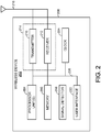
- FIG. 2 illustrates various components that may be utilized in a wireless device 202 that may be employed within the wireless communication system 100 or 160.
- the wireless device 202 is an example of a device that may be configured to implement the various methods described herein.
- the wireless device 202 may comprise the AP 104 or one of the STAs.
- the wireless device 202 may include a processor 204 which controls operation of the wireless device 202.
- the processor 204 may also be referred to as a central processing unit (CPU).
- Memory 206 which may include both read-only memory (ROM) and random access memory (RAM), may provide instructions and data to the processor 204.
- a portion of the memory 206 may also include non-volatile random access memory (NVRAM).
- the processor 204 typically performs logical and arithmetic operations based on program instructions stored within the memory 206.
- the instructions in the memory 206 may be executable to implement the methods described herein.
- the processor 204 may comprise or be a component of a processing system implemented with one or more processors.
- the one or more processors may be implemented with any combination of general-purpose microprocessors, microcontrollers, digital signal processors (DSPs), field programmable gate array (FPGAs), programmable logic devices (PLDs), controllers, state machines, gated logic, discrete hardware components, dedicated hardware finite state machines, or any other suitable entities that can perform calculations or other manipulations of information.
- the processing system may also include machine-readable media for storing software.
- Software shall be construed broadly to mean any type of instructions, whether referred to as software, firmware, middleware, microcode, hardware description language, or otherwise. Instructions may include code (e.g., in source code format, binary code format, executable code format, or any other suitable format of code). The instructions, when executed by the one or more processors, cause the processing system to perform the various functions described herein.
- the wireless device 202 may include a clock 224 configured to generate a clock signal that is used to coordinate and synchronize activities of the wireless device 202.
- the processor 204 may include the clock 224.
- the processor 204 may be configured to update the clock with a time value to allow for synchronization with other wireless devices.
- the wireless device 202 may also include a housing 208 that may include a transmitter 210 and/or a receiver 212 to allow transmission and reception of data between the wireless device 202 and a remote location.
- the transmitter 210 and receiver 212 may be combined into a transceiver 214.
- An antenna 216 may be attached to the housing 208 and electrically coupled to the transceiver 214.
- the wireless device 202 may also include (not shown) multiple transmitters, multiple receivers, multiple transceivers, and/or multiple antennas.
- the transmitter 210 may be configured to wirelessly transmit packets having different packet types or functions.
- the transmitter 210 may be configured to transmit packets of different types generated by the processor 204.
- the processor 204 may be configured to process packets of a plurality of different packet types.
- the processor 204 may be configured to determine the type of packet and to process the packet and/or fields of the packet accordingly.
- the processor 204 may also be configured to select and generate one of a plurality of packet types.
- the processor 204 may be configured to generate a discovery packet comprising a discovery message and to determine what type of packet information to use in a particular instance.
- the receiver 212 may be configured to wirelessly receive packets having different packet types. In some aspects, the receiver 212 may be configured to detect a type of a packet used and to process the packet accordingly.
- the wireless device 202 may also include a signal detector 218 that may be used in an effort to detect and quantify the level of signals received by the transceiver 214.
- the signal detector 218 may detect such signals as total energy, energy per subcarrier per symbol, power spectral density and other signals.
- the wireless device 202 may also include a digital signal processor (DSP) 220 for use in processing signals.
- DSP 220 may be configured to generate a packet for transmission.
- the packet may comprise a physical layer data unit (PPDU).
- PPDU physical layer data unit
- the wireless device 202 may further comprise a user interface 222 in some aspects.
- the user interface 222 may comprise a keypad, a microphone, a speaker, and/or a display.
- the user interface 222 may include any element or component that conveys information to a user of the wireless device 202 and/or receives input from the user.
- the various components of the wireless device 202 may be coupled together by a bus system 226.
- the bus system 226 may include a data bus, for example, as well as a power bus, a control signal bus, and a status signal bus in addition to the data bus.
- the components of the wireless device 202 may be coupled together or accept or provide inputs to each other using some other mechanism.
- processor 204 may be used to implement not only the functionality described above with respect to the processor 204, but also to implement the functionality described above with respect to the signal detector 218 and/or the DSP 220. Further, each of the components illustrated in FIG. 2 may be implemented using a plurality of separate elements.
- Devices such as STAs, 106a-i shown in FIG. 1b , for example, may be used for neighborhood-aware networking, or social-WiFi networking.
- various stations within the network may communicate on a device to device (e.g., peer-to-peer communications) basis with one another regarding applications that each of the stations supports.
- a discovery protocol may be used in a social-WiFi network to enable STAs to advertise themselves (e.g., by sending discovery packets) as well as discover services provided by other STAs (e.g., by sending paging or query packets), while ensuring secure communication and low power consumption.
- one device such as wireless device 202, in the network may be designated as the root device or node.
- the root device may be an ordinary device, like the other devices in the network, rather than a specialized device such as a router.
- the root node may be responsible for periodically transmitting synchronization messages, or synchronization signals or frames, to other nodes in the network.
- the synchronization messages transmitted by root node may provide a timing reference for other nodes to coordinate an availability window during which communication occurs between the nodes.
- the synchronization message may also provide updates to a schedule for future availability windows.
- the synchronization messages may also function to notify STAs that they are still present in the peer to peer network.
- Each device in the network may have a clock, such as clock 224 in wireless device 202.
- This clock may be an internal clock, built in to the device when it was constructed. This clock may be configured to generate a clock signal that is used to coordinate and synchronize activities of the device. However, this clock may have some amount of clock drift, where clock drift may represent the difference between the clock signals generated by the clock and clock signals that may be generated by an ideal clock. This clock drift may be present in the clock of the root node as well as in clocks on branch nodes and leaf nodes in a social-WiFi network.
- Clock drift may be random, or may be constant to some extent.
- Clock drift may be expressed in a number of ways.
- This formula may provide an approximation of clock drift. This approximation may be more or less accurate, depending upon the nature of the clock drift. For example, if clock drift is constant or nearly constant, this formula may provide a very accurate approximation of clock drift, as long as d n can be accurately calculated.
- the clock drift d n may be either positive or negative, corresponding to a clock that is either too fast or too slow.
- Clock drift may introduce a certain amount of synchronization error to the network.
- devices on the network may use synchronization messages transmitted by a root device and retransmitted by branch devices in order to determine availability windows. During these availability windows, devices in the social-WiFi network may be configured to transmit and/or receive messages from other devices on the network. At other times, devices, or portions of devices, on the social-WiFi network may be in a sleep state. For example, a device on a social-WiFi network, such as wireless device 202, may enter a sleep state based at least in part on synchronization messages received from a root node.
- devices on a social-WiFi network may enter a sleep mode, where one or more elements of the device may enter a sleep mode, rather than the entire device.
- wireless device 202 may enter a sleep mode where the transmitter 210, receiver 212, and/or transceiver 214 may enter a sleep mode based on synchronization messages received on a social-WiFi network. This sleep mode may enable a wireless device 202 to conserve power or battery life.
- FIG. 3 illustrates an example of a communication system in which aspects of the present disclosure may be employed.
- Wireless device 300 may be a wireless device, such as wireless device 200.
- Wireless device 300 may be the root node of a peer-to-peer network, such as social-WiFi network 320.
- Wireless device 300 may be configured to transmit messages 310 to other devices on the social-WiFi network 320.
- As the root device wireless device 300 may be configured to transmit synchronization messages on some interval to other devices on the social-WiFi network 320.
- Wireless devices 302 and 304 may be nodes on the social-WiFi network 320. Wireless devices 302 and 304 may be branch nodes or leaf nodes on the network 320. As nodes on the social-WiFi network 320, wireless devices 302 and 304 may transmit messages 312 and 314 to other devices on the network 320. These messages may be transmitted to other devices during an availability window, during which time each device is configured to transmit and/or receive transmissions from other wireless devices on the network 320. For example, wireless device 302 may transmit messages 312 to wireless device 304 during an availability window for both devices, where the availability windows is based in part upon a synchronization message received from wireless device 300.
- clock drift may introduce synchronization error into the network 320.
- each wireless device 300, 302 and 304 may have a clock drift.
- Wireless device 300 may, as the root node, periodically transmit synchronization messages.
- synchronization messages may indicate the frequency of availability windows for devices in the network 320, and may further indicate the frequency of synchronization messages and/or the interval until the next synchronization message.
- a social-WiFi network 320 may have a synchronization error.
- This synchronization error may be expressed as a number of seconds, such as 0.001, 0.01, 0.1, 1 or another amount of seconds.
- This synchronization error may indicate the amount of clock drift between synchronization messages.
- X
- a device with a synchronization error that is too high may be unable to remain connected to a social-WiFi network.
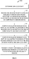
- FIG. 4 is a flowchart of a method for transmitting synchronization frames on a social-WiFi network. This method may be executed by a root node of the social-WiFi network, which may be a device such as wireless device 202.
- the root node determines the largest clock drift in a network.
- This clock drift may be expressed as d r as discussed above.
- a large clock drift may represent a device which has an internal clock that is too fast.
- the root node determines the smallest clock drift in a network.
- This clock drift may be expressed as d r as discussed above. Because clock drifts may be either a positive or a negative number, the smallest clock drift in a network may be a negative number.
- a negative clock drift may represent a device which has an internal clock that is too slow.
- the root node determines its own clock drift.
- This clock drift may be programmed into a root node, or the root node may be able to determine its own clock drift.
- the root node may be able to determine its own clock drift based upon a comparison between its own internal clock and an accurate external timing source, such as a GPS satellite or other source.
- the root node calculates an optimized synchronization frame interval based on a synchronization error threshold, the largest and smallest clock drifts in the network and the root node's own clock drift.
- a synchronization error threshold may be calculated in a number of ways.
- a social-WiFi network may have a maximum synchronization error threshold, ⁇ .
- This maximum synchronization error threshold may represent the maximum allowable synchronization error for any device in a network.
- This maximum synchronization error threshold may be based, at least in part, on the length of an availability window on the network. For example, if an availability window of a device on the network is longer, the maximum synchronization error threshold may also be longer.
- the length of availability windows of devices on the network may be standardized for a networking protocol, such as social-WiFi, or may be determined based, at least in part, on information contained in a synchronization message or another message transmitted on the network. Determining the length of an availability window may represent a trade-off between battery life and network overhead, as longer availability windows may require more power while shorter availability windows may require more network overhead in the form of more frequent synchronization messages.
- the maximum synchronization error threshold may be set in a number of ways. For example, the maximum synchronization error threshold may be set on a device at the factory when the device is constructed, or may be acquired from a server. The root device may acquire the maximum synchronization error threshold by checking a server, if connecting to the server is possible.
- synchronization messages should be transmitted no later than the following upper limit: X ⁇ ⁇
- the root device should send a synchronization frame no less frequently than X ⁇ ⁇ max n
- This formula may be used for each and every device on the network, and the value of X may be set so that the formula is true for each device on the network.
- the root node will only need to use this formula twice at block 406 in order to calculate an optimized synchronization frame interval.
- the root device may be configured to send synchronization messages at least as often as X r seconds, as shown on the clock of the root device.
- this formula is an example of a formula that may be used to calculate an optimized synchronization frame interval, based at least in part on the largest and smallest clock drifts, as in block 406.
- the denominator of the above formula may be calculated using the formula max n
- max
- a root node may have an absolute maximum or minimum clock drift.
- the root device may use the absolute maximum clock drift to calculate an optimized synchronization frame frequency rather than the largest clock drift on the network, if the largest clock drift on the network is too large. While this may result in some devices becoming unable to remain connected to the network, this may be necessary in order to reduce network overhead.
- a root device may have a minimum synchronization frame interval, and may use this interval rather than the calculated optimal synchronization frame interval if the minimum synchronization frame interval is larger than the optimal synchronization frame interval. This may be beneficial in order to reduce network overhead.
- a root device may have a maximum synchronization frame interval, and may use this interval rather than the calculated optimal synchronization frame interval if the maximum synchronization frame interval is smaller than the optimal synchronization frame interval. This may be beneficial in order to allow new devices to remain connected to the network, or in case some devices may not correctly be reporting their own clock drifts.
- the method may transmit a synchronization frame based at least in part on the optimized synchronization frame interval.
- the time at which this synchronization frame is transmitted may be based, at least in part, on the calculation of an optimized synchronization frame interval.
- the synchronization frame may indicate when a next synchronization frame may be transmitted. The timing of the next synchronization frame may be based, at least in part, upon the calculation of the optimized synchronization frame interval.
- FIG. 5 is a flowchart of a method for transmitting clock drift information on a social-WiFi network. This method may be executed by a wireless device on a social-WiFi network, such as wireless device 202.
- the wireless device determines its own clock drift.
- each wireless device on a social-WiFi network may have information about its own clock drift d n .
- this information may be programmed onto a wireless device at the time the wireless device is made or programmed.
- the clock of a wireless device may be tested at a factory or other facility, or may contain a known error, which may be programmed into the device at the time the device is constructed.
- a wireless device may be able to calculate its own clock drift.
- a wireless device may have access to an accurate external timing reference, such as a clock on a global positioning system (GPS) satellite or a cellular tower.
- GPS global positioning system
- a wireless device may also have access to an accurate external timing reference through a network such as the internet.
- the wireless device may use this access to an accurate external timing reference in order to measure its own clock drift by comparing a duration of time on the accurate external timing reference with a duration of time on its own internal clock.
- the wireless device may be configured to recalibrate its clock drift on some set interval, and/or may be configured to recalibrate its clock drift when, for example, the wireless device finds that it has become de-synchronized from a social-WiFi network.
- the wireless device receives one or more packets during an availability window containing maximum and minimum clock drifts of devices on a network, as computed by a sending device.
- This packet may be any type of packet.
- this packet may be a discovery packet.
- the wireless device computes an adjusted maximum clock drift, by calculating the maximum of its own clock drift and each received maximum clock drift in the one or more packets.
- the wireless device computes an adjusted minimum clock drift, by calculating the minimum of its own clock drift and each received minimum clock drift in the one or more packets.
- the wireless device transmits a packet containing adjusted maximum and minimum clock drifts on the network during an availability window. For example, the wireless device may transmit adjusted maximum and minimum clock drifts in its next packet, during a later availability window.
- a wireless network may periodically reset the maximum and minimum clock drifts on the network. For example, as devices may leave the network, the maximum and minimum clock drift of any device on the network may change. However, this change may not be observed using the method of FIG. 5 on its own. Therefore, it may be beneficial for a root device to periodically send "reset" messages in a packet, such as a synchronization frame. Upon receiving a "reset" message, each wireless device on a network may reset both its adjusted maximum clock drift and adjusted minimum clock drift to correspond to that device's own clock drift. In future availability windows, the method of FIG. 5 may continue to be used, but these "reset” messages may allow the maximum and minimum clock drifts on the network to reset, and to accommodate for when some devices leave the network, which may change the maximum and minimum clock drifts on the network.
- any reference to an element herein using a designation such as “first,” “second,” and so forth does not generally limit the quantity or order of those elements. Rather, these designations may be used herein as a convenient wireless device of distinguishing between two or more elements or instances of an element. Thus, a reference to first and second elements does not mean that only two elements may be employed there or that the first element must precede the second element in some manner. Also, unless stated otherwise a set of elements may include one or more elements.
- any of the various illustrative logical blocks, modules, processors, means, circuits, and algorithm steps described in connection with the aspects disclosed herein may be implemented as electronic hardware (e.g., a digital implementation, an analog implementation, or a combination of the two, which may be designed using source coding or some other technique), various forms of program or design code incorporating instructions (which may be referred to herein, for convenience, as "software” or a "software module), or combinations of both.
- software or a “software module”
- the various illustrative logical blocks, modules, and circuits described in connection with the aspects disclosed herein and in connection with FIGS. 1-11 may be implemented within or performed by an integrated circuit (IC), an access terminal, or an access point.
- the IC may include a general purpose processor, a digital signal processor (DSP), an application specific integrated circuit (ASIC), a field programmable gate array (FPGA) or other programmable logic device, discrete gate or transistor logic, discrete hardware components, electrical components, optical components, mechanical components, or any combination thereof designed to perform the functions described herein, and may execute codes or instructions that reside within the IC, outside of the IC, or both.
- the logical blocks, modules, and circuits may include antennas and/or transceivers to communicate with various components within the network or within the device.
- a general purpose processor may be a microprocessor, but in the alternative, the processor may be any conventional processor, controller, microcontroller, or state machine.
- a processor may also be implemented as a combination of computing devices, e.g., a combination of a DSP and a microprocessor, a plurality of microprocessors, one or more microprocessors in conjunction with a DSP core, or any other such configuration.
- the functionality of the modules may be implemented in some other manner as taught herein.
- the functionality described herein (e.g., with regard to one or more of the accompanying figures) may correspond in some aspects to similarly designated "means for" functionality in the appended claims.
- Computer-readable media includes both computer storage media and communication media including any medium that can be enabled to transfer a computer program from one place to another.
- a storage media may be any available media that may be accessed by a computer.
- such computer-readable media may include RAM, ROM, EEPROM, CD-ROM or other optical disk storage, magnetic disk storage or other magnetic storage devices, or any other medium that may be used to store desired program code in the form of instructions or data structures and that may be accessed by a computer.
- Disk and disc includes compact disc (CD), laser disc, optical disc, digital versatile disc (DVD), floppy disk, and blu-ray disc where disks usually reproduce data magnetically, while discs reproduce data optically with lasers. Combinations of the above should also be included within the scope of computer-readable media. Additionally, the operations of a method or algorithm may reside as one or any combination or set of codes and instructions on a machine readable medium and computer-readable medium, which may be incorporated into a computer program product.
Landscapes
- Engineering & Computer Science (AREA)
- Computer Networks & Wireless Communication (AREA)
- Signal Processing (AREA)
- Mobile Radio Communication Systems (AREA)
Applications Claiming Priority (4)
| Application Number | Priority Date | Filing Date | Title |
|---|---|---|---|
| US201261732032P | 2012-11-30 | 2012-11-30 | |
| US201261735789P | 2012-12-11 | 2012-12-11 | |
| US13/789,425 US9226251B2 (en) | 2012-11-30 | 2013-03-07 | Systems and methods for optimization of synchronization message transmission intervals in a peer-to-peer network |
| PCT/US2013/070823 WO2014085144A1 (en) | 2012-11-30 | 2013-11-19 | Systems and methods for optimization of synchronization message transmission intervals in a peer-to-peer network |
Publications (2)
| Publication Number | Publication Date |
|---|---|
| EP2926606A1 EP2926606A1 (en) | 2015-10-07 |
| EP2926606B1 true EP2926606B1 (en) | 2018-05-30 |
Family
ID=50825405
Family Applications (1)
| Application Number | Title | Priority Date | Filing Date |
|---|---|---|---|
| EP13798523.0A Not-in-force EP2926606B1 (en) | 2012-11-30 | 2013-11-19 | Systems and methods for optimization of synchronization message transmission intervals in a peer-to-peer network |
Country Status (5)
| Country | Link |
|---|---|
| US (1) | US9226251B2 (cg-RX-API-DMAC7.html) |
| EP (1) | EP2926606B1 (cg-RX-API-DMAC7.html) |
| JP (1) | JP2016504835A (cg-RX-API-DMAC7.html) |
| CN (1) | CN104823494A (cg-RX-API-DMAC7.html) |
| WO (1) | WO2014085144A1 (cg-RX-API-DMAC7.html) |
Families Citing this family (5)
| Publication number | Priority date | Publication date | Assignee | Title |
|---|---|---|---|---|
| US10342068B2 (en) * | 2015-02-10 | 2019-07-02 | Lg Electronics Inc. | Method for transmitting data in wireless communication system and device using same |
| CN107736059B (zh) | 2015-06-17 | 2021-02-09 | 瑞典爱立信有限公司 | 一种具有稀疏同步信号速率的系统中的信号检测方法 |
| KR102386807B1 (ko) * | 2018-08-27 | 2022-04-14 | 구글 엘엘씨 | 메시 네트워크에서 동기화된 수신 |
| CN110213007B (zh) * | 2019-06-24 | 2021-08-03 | 腾讯科技(深圳)有限公司 | 一种时钟漂移处理的方法、网络功能网元及存储介质 |
| CN113055996B (zh) * | 2021-03-09 | 2022-09-16 | Oppo广东移动通信有限公司 | 时钟漂移的监控方法、装置、终端、服务器及存储介质 |
Citations (1)
| Publication number | Priority date | Publication date | Assignee | Title |
|---|---|---|---|---|
| US20060133408A1 (en) * | 2004-11-15 | 2006-06-22 | Juan Nogueira-Nine | Beaconless communication system |
Family Cites Families (20)
| Publication number | Priority date | Publication date | Assignee | Title |
|---|---|---|---|---|
| US6310886B1 (en) * | 1997-08-28 | 2001-10-30 | Tivo, Inc. | Method and apparatus implementing a multimedia digital network |
| EP1247368B1 (en) * | 2000-01-14 | 2006-05-31 | Addvalue Technologies Ltd. | Communication apparatus |
| EP1211824B1 (de) * | 2000-12-01 | 2008-08-06 | Siemens Enterprise Communications GmbH & Co. KG | Verfahren zum Synchronisieren von an verschiedene Vermittlungssystemteile gekoppelten Basisstationen eines Mobilfunknetzes |
| US7072432B2 (en) | 2002-07-05 | 2006-07-04 | Meshnetworks, Inc. | System and method for correcting the clock drift and maintaining the synchronization of low quality clocks in wireless networks |
| JP3846715B2 (ja) * | 2002-09-30 | 2006-11-15 | ソニー株式会社 | 無線通信システム |
| US7406105B2 (en) * | 2004-03-03 | 2008-07-29 | Alfred E. Mann Foundation For Scientific Research | System and method for sharing a common communication channel between multiple systems of implantable medical devices |
| US7623552B2 (en) | 2004-10-14 | 2009-11-24 | Temic Automotive Of North America, Inc. | System and method for time synchronizing nodes in an automotive network using input capture |
| WO2008035140A1 (en) * | 2006-09-19 | 2008-03-27 | Nxp B.V. | Method and system for synchronizing a local clock in a wireless device to a host clock in a wireless host |
| US20080212690A1 (en) * | 2007-03-01 | 2008-09-04 | Qualcomm Incorporated | Transcoder media time conversion |
| US20080240163A1 (en) * | 2007-04-02 | 2008-10-02 | Texas Instruments Incorporated | System and method for maintaining transmission synchrony |
| CN101731011B (zh) * | 2007-05-11 | 2014-05-28 | 奥迪耐特有限公司 | 用于设置接收器延迟时间的方法 |
| KR101508369B1 (ko) * | 2007-09-19 | 2015-04-06 | 텔레콤 이탈리아 소시에떼 퍼 아찌오니 | 비동기식 무선 통신 네트워크 내에서 정보 패킷들을 전송하기 위한 방법 및 그 방법을 구현하는 네트워크 노드 |
| US7957343B2 (en) | 2008-03-06 | 2011-06-07 | Qualcomm Incorporated | Motion-aware mobile time and frequency tracking |
| JP5163890B2 (ja) * | 2008-07-22 | 2013-03-13 | 横河電機株式会社 | 無線通信システム |
| CN101466142B (zh) * | 2009-01-08 | 2011-02-09 | 上海交通大学 | 无线传感器网络中分层时间比较时钟同步方法 |
| GB201000012D0 (en) * | 2010-01-04 | 2010-02-17 | Cambridge Silicon Radio | Transmission timing adjustment in radio systems |
| US8837530B2 (en) * | 2010-03-12 | 2014-09-16 | University Of Maryland | Method and system for adaptive synchronization of timing information generated by independently clocked communication nodes |
| EP2429105B1 (en) * | 2010-09-13 | 2013-03-27 | Ntt Docomo, Inc. | Node in a wireless system with time and clock frequency synchronizing and corresponding method |
| CN102083183A (zh) * | 2011-03-07 | 2011-06-01 | 杭州电子科技大学 | 一种无线传感网络的相对时间同步的低能耗休眠侦听方法 |
| EP2544387B1 (en) | 2011-07-04 | 2016-03-16 | Mitsubishi Electric R&D Centre Europe B.V. | Methods and devices for performing synchronization and compensating clock drift among communication devices |
-
2013
- 2013-03-07 US US13/789,425 patent/US9226251B2/en not_active Expired - Fee Related
- 2013-11-19 CN CN201380062342.XA patent/CN104823494A/zh active Pending
- 2013-11-19 JP JP2015545095A patent/JP2016504835A/ja not_active Ceased
- 2013-11-19 EP EP13798523.0A patent/EP2926606B1/en not_active Not-in-force
- 2013-11-19 WO PCT/US2013/070823 patent/WO2014085144A1/en not_active Ceased
Patent Citations (1)
| Publication number | Priority date | Publication date | Assignee | Title |
|---|---|---|---|---|
| US20060133408A1 (en) * | 2004-11-15 | 2006-06-22 | Juan Nogueira-Nine | Beaconless communication system |
Also Published As
| Publication number | Publication date |
|---|---|
| JP2016504835A (ja) | 2016-02-12 |
| CN104823494A (zh) | 2015-08-05 |
| US9226251B2 (en) | 2015-12-29 |
| EP2926606A1 (en) | 2015-10-07 |
| WO2014085144A1 (en) | 2014-06-05 |
| US20140153560A1 (en) | 2014-06-05 |
Similar Documents
| Publication | Publication Date | Title |
|---|---|---|
| EP2979468B1 (en) | Systems and methods for synchronization within a neighborhood aware network | |
| US9800389B2 (en) | Systems and methods for discovering and synchronizing within a neighbor aware network | |
| US9408171B2 (en) | Systems and methods for synchronization of wireless devices in a peer-to-peer network | |
| US9872227B2 (en) | Systems and methods for identification in a neighborhood aware network | |
| US9843995B2 (en) | Method and metrics for merging with a neighborhood aware network | |
| US20140192793A1 (en) | Systems and methods for hierarchical time source usage in near-me area network discovery and synchronization | |
| EP3216281B1 (en) | Systems and methods for synchronization within a neighborhood aware network | |
| US9301158B2 (en) | Systems and methods for optimization of branch synchronization node determination in a peer-to-peer network | |
| EP2926606B1 (en) | Systems and methods for optimization of synchronization message transmission intervals in a peer-to-peer network | |
| EP3066876B1 (en) | Systems, apparatus and methods for synchronizing a global time reference for access points over the air |
Legal Events
| Date | Code | Title | Description |
|---|---|---|---|
| PUAI | Public reference made under article 153(3) epc to a published international application that has entered the european phase |
Free format text: ORIGINAL CODE: 0009012 |
|
| 17P | Request for examination filed |
Effective date: 20150513 |
|
| AK | Designated contracting states |
Kind code of ref document: A1 Designated state(s): AL AT BE BG CH CY CZ DE DK EE ES FI FR GB GR HR HU IE IS IT LI LT LU LV MC MK MT NL NO PL PT RO RS SE SI SK SM TR |
|
| AX | Request for extension of the european patent |
Extension state: BA ME |
|
| DAX | Request for extension of the european patent (deleted) | ||
| 17Q | First examination report despatched |
Effective date: 20170210 |
|
| GRAP | Despatch of communication of intention to grant a patent |
Free format text: ORIGINAL CODE: EPIDOSNIGR1 |
|
| INTG | Intention to grant announced |
Effective date: 20171213 |
|
| GRAS | Grant fee paid |
Free format text: ORIGINAL CODE: EPIDOSNIGR3 |
|
| GRAA | (expected) grant |
Free format text: ORIGINAL CODE: 0009210 |
|
| AK | Designated contracting states |
Kind code of ref document: B1 Designated state(s): AL AT BE BG CH CY CZ DE DK EE ES FI FR GB GR HR HU IE IS IT LI LT LU LV MC MK MT NL NO PL PT RO RS SE SI SK SM TR |
|
| REG | Reference to a national code |
Ref country code: GB Ref legal event code: FG4D |
|
| REG | Reference to a national code |
Ref country code: CH Ref legal event code: EP |
|
| REG | Reference to a national code |
Ref country code: AT Ref legal event code: REF Ref document number: 1004955 Country of ref document: AT Kind code of ref document: T Effective date: 20180615 |
|
| REG | Reference to a national code |
Ref country code: IE Ref legal event code: FG4D |
|
| REG | Reference to a national code |
Ref country code: DE Ref legal event code: R096 Ref document number: 602013038278 Country of ref document: DE |
|
| REG | Reference to a national code |
Ref country code: NL Ref legal event code: MP Effective date: 20180530 |
|
| REG | Reference to a national code |
Ref country code: LT Ref legal event code: MG4D |
|
| PG25 | Lapsed in a contracting state [announced via postgrant information from national office to epo] |
Ref country code: ES Free format text: LAPSE BECAUSE OF FAILURE TO SUBMIT A TRANSLATION OF THE DESCRIPTION OR TO PAY THE FEE WITHIN THE PRESCRIBED TIME-LIMIT Effective date: 20180530 Ref country code: BG Free format text: LAPSE BECAUSE OF FAILURE TO SUBMIT A TRANSLATION OF THE DESCRIPTION OR TO PAY THE FEE WITHIN THE PRESCRIBED TIME-LIMIT Effective date: 20180830 Ref country code: CY Free format text: LAPSE BECAUSE OF FAILURE TO SUBMIT A TRANSLATION OF THE DESCRIPTION OR TO PAY THE FEE WITHIN THE PRESCRIBED TIME-LIMIT Effective date: 20180530 Ref country code: LT Free format text: LAPSE BECAUSE OF FAILURE TO SUBMIT A TRANSLATION OF THE DESCRIPTION OR TO PAY THE FEE WITHIN THE PRESCRIBED TIME-LIMIT Effective date: 20180530 Ref country code: FI Free format text: LAPSE BECAUSE OF FAILURE TO SUBMIT A TRANSLATION OF THE DESCRIPTION OR TO PAY THE FEE WITHIN THE PRESCRIBED TIME-LIMIT Effective date: 20180530 Ref country code: SE Free format text: LAPSE BECAUSE OF FAILURE TO SUBMIT A TRANSLATION OF THE DESCRIPTION OR TO PAY THE FEE WITHIN THE PRESCRIBED TIME-LIMIT Effective date: 20180530 Ref country code: NO Free format text: LAPSE BECAUSE OF FAILURE TO SUBMIT A TRANSLATION OF THE DESCRIPTION OR TO PAY THE FEE WITHIN THE PRESCRIBED TIME-LIMIT Effective date: 20180830 |
|
| PG25 | Lapsed in a contracting state [announced via postgrant information from national office to epo] |
Ref country code: RS Free format text: LAPSE BECAUSE OF FAILURE TO SUBMIT A TRANSLATION OF THE DESCRIPTION OR TO PAY THE FEE WITHIN THE PRESCRIBED TIME-LIMIT Effective date: 20180530 Ref country code: LV Free format text: LAPSE BECAUSE OF FAILURE TO SUBMIT A TRANSLATION OF THE DESCRIPTION OR TO PAY THE FEE WITHIN THE PRESCRIBED TIME-LIMIT Effective date: 20180530 Ref country code: HR Free format text: LAPSE BECAUSE OF FAILURE TO SUBMIT A TRANSLATION OF THE DESCRIPTION OR TO PAY THE FEE WITHIN THE PRESCRIBED TIME-LIMIT Effective date: 20180530 Ref country code: GR Free format text: LAPSE BECAUSE OF FAILURE TO SUBMIT A TRANSLATION OF THE DESCRIPTION OR TO PAY THE FEE WITHIN THE PRESCRIBED TIME-LIMIT Effective date: 20180831 |
|
| REG | Reference to a national code |
Ref country code: AT Ref legal event code: MK05 Ref document number: 1004955 Country of ref document: AT Kind code of ref document: T Effective date: 20180530 |
|
| PG25 | Lapsed in a contracting state [announced via postgrant information from national office to epo] |
Ref country code: NL Free format text: LAPSE BECAUSE OF FAILURE TO SUBMIT A TRANSLATION OF THE DESCRIPTION OR TO PAY THE FEE WITHIN THE PRESCRIBED TIME-LIMIT Effective date: 20180530 |
|
| PG25 | Lapsed in a contracting state [announced via postgrant information from national office to epo] |
Ref country code: RO Free format text: LAPSE BECAUSE OF FAILURE TO SUBMIT A TRANSLATION OF THE DESCRIPTION OR TO PAY THE FEE WITHIN THE PRESCRIBED TIME-LIMIT Effective date: 20180530 Ref country code: CZ Free format text: LAPSE BECAUSE OF FAILURE TO SUBMIT A TRANSLATION OF THE DESCRIPTION OR TO PAY THE FEE WITHIN THE PRESCRIBED TIME-LIMIT Effective date: 20180530 Ref country code: SK Free format text: LAPSE BECAUSE OF FAILURE TO SUBMIT A TRANSLATION OF THE DESCRIPTION OR TO PAY THE FEE WITHIN THE PRESCRIBED TIME-LIMIT Effective date: 20180530 Ref country code: PL Free format text: LAPSE BECAUSE OF FAILURE TO SUBMIT A TRANSLATION OF THE DESCRIPTION OR TO PAY THE FEE WITHIN THE PRESCRIBED TIME-LIMIT Effective date: 20180530 Ref country code: AT Free format text: LAPSE BECAUSE OF FAILURE TO SUBMIT A TRANSLATION OF THE DESCRIPTION OR TO PAY THE FEE WITHIN THE PRESCRIBED TIME-LIMIT Effective date: 20180530 Ref country code: EE Free format text: LAPSE BECAUSE OF FAILURE TO SUBMIT A TRANSLATION OF THE DESCRIPTION OR TO PAY THE FEE WITHIN THE PRESCRIBED TIME-LIMIT Effective date: 20180530 Ref country code: DK Free format text: LAPSE BECAUSE OF FAILURE TO SUBMIT A TRANSLATION OF THE DESCRIPTION OR TO PAY THE FEE WITHIN THE PRESCRIBED TIME-LIMIT Effective date: 20180530 |
|
| PG25 | Lapsed in a contracting state [announced via postgrant information from national office to epo] |
Ref country code: IT Free format text: LAPSE BECAUSE OF FAILURE TO SUBMIT A TRANSLATION OF THE DESCRIPTION OR TO PAY THE FEE WITHIN THE PRESCRIBED TIME-LIMIT Effective date: 20180530 Ref country code: SM Free format text: LAPSE BECAUSE OF FAILURE TO SUBMIT A TRANSLATION OF THE DESCRIPTION OR TO PAY THE FEE WITHIN THE PRESCRIBED TIME-LIMIT Effective date: 20180530 |
|
| REG | Reference to a national code |
Ref country code: DE Ref legal event code: R097 Ref document number: 602013038278 Country of ref document: DE |
|
| PLBE | No opposition filed within time limit |
Free format text: ORIGINAL CODE: 0009261 |
|
| STAA | Information on the status of an ep patent application or granted ep patent |
Free format text: STATUS: NO OPPOSITION FILED WITHIN TIME LIMIT |
|
| 26N | No opposition filed |
Effective date: 20190301 |
|
| PG25 | Lapsed in a contracting state [announced via postgrant information from national office to epo] |
Ref country code: SI Free format text: LAPSE BECAUSE OF FAILURE TO SUBMIT A TRANSLATION OF THE DESCRIPTION OR TO PAY THE FEE WITHIN THE PRESCRIBED TIME-LIMIT Effective date: 20180530 |
|
| REG | Reference to a national code |
Ref country code: CH Ref legal event code: PL |
|
| PG25 | Lapsed in a contracting state [announced via postgrant information from national office to epo] |
Ref country code: MC Free format text: LAPSE BECAUSE OF FAILURE TO SUBMIT A TRANSLATION OF THE DESCRIPTION OR TO PAY THE FEE WITHIN THE PRESCRIBED TIME-LIMIT Effective date: 20180530 Ref country code: LU Free format text: LAPSE BECAUSE OF NON-PAYMENT OF DUE FEES Effective date: 20181119 |
|
| REG | Reference to a national code |
Ref country code: BE Ref legal event code: MM Effective date: 20181130 |
|
| REG | Reference to a national code |
Ref country code: IE Ref legal event code: MM4A |
|
| PG25 | Lapsed in a contracting state [announced via postgrant information from national office to epo] |
Ref country code: LI Free format text: LAPSE BECAUSE OF NON-PAYMENT OF DUE FEES Effective date: 20181130 Ref country code: CH Free format text: LAPSE BECAUSE OF NON-PAYMENT OF DUE FEES Effective date: 20181130 |
|
| PG25 | Lapsed in a contracting state [announced via postgrant information from national office to epo] |
Ref country code: IE Free format text: LAPSE BECAUSE OF NON-PAYMENT OF DUE FEES Effective date: 20181119 |
|
| PG25 | Lapsed in a contracting state [announced via postgrant information from national office to epo] |
Ref country code: BE Free format text: LAPSE BECAUSE OF NON-PAYMENT OF DUE FEES Effective date: 20181130 Ref country code: AL Free format text: LAPSE BECAUSE OF FAILURE TO SUBMIT A TRANSLATION OF THE DESCRIPTION OR TO PAY THE FEE WITHIN THE PRESCRIBED TIME-LIMIT Effective date: 20180530 |
|
| PG25 | Lapsed in a contracting state [announced via postgrant information from national office to epo] |
Ref country code: MT Free format text: LAPSE BECAUSE OF NON-PAYMENT OF DUE FEES Effective date: 20181119 |
|
| PGFP | Annual fee paid to national office [announced via postgrant information from national office to epo] |
Ref country code: DE Payment date: 20191017 Year of fee payment: 7 |
|
| PGFP | Annual fee paid to national office [announced via postgrant information from national office to epo] |
Ref country code: FR Payment date: 20191029 Year of fee payment: 7 |
|
| PG25 | Lapsed in a contracting state [announced via postgrant information from national office to epo] |
Ref country code: TR Free format text: LAPSE BECAUSE OF FAILURE TO SUBMIT A TRANSLATION OF THE DESCRIPTION OR TO PAY THE FEE WITHIN THE PRESCRIBED TIME-LIMIT Effective date: 20180530 |
|
| PGFP | Annual fee paid to national office [announced via postgrant information from national office to epo] |
Ref country code: GB Payment date: 20191029 Year of fee payment: 7 |
|
| PG25 | Lapsed in a contracting state [announced via postgrant information from national office to epo] |
Ref country code: PT Free format text: LAPSE BECAUSE OF FAILURE TO SUBMIT A TRANSLATION OF THE DESCRIPTION OR TO PAY THE FEE WITHIN THE PRESCRIBED TIME-LIMIT Effective date: 20180530 |
|
| PG25 | Lapsed in a contracting state [announced via postgrant information from national office to epo] |
Ref country code: HU Free format text: LAPSE BECAUSE OF FAILURE TO SUBMIT A TRANSLATION OF THE DESCRIPTION OR TO PAY THE FEE WITHIN THE PRESCRIBED TIME-LIMIT; INVALID AB INITIO Effective date: 20131119 Ref country code: MK Free format text: LAPSE BECAUSE OF NON-PAYMENT OF DUE FEES Effective date: 20180530 |
|
| PG25 | Lapsed in a contracting state [announced via postgrant information from national office to epo] |
Ref country code: IS Free format text: LAPSE BECAUSE OF FAILURE TO SUBMIT A TRANSLATION OF THE DESCRIPTION OR TO PAY THE FEE WITHIN THE PRESCRIBED TIME-LIMIT Effective date: 20180930 |
|
| REG | Reference to a national code |
Ref country code: DE Ref legal event code: R119 Ref document number: 602013038278 Country of ref document: DE |
|
| GBPC | Gb: european patent ceased through non-payment of renewal fee |
Effective date: 20201119 |
|
| PG25 | Lapsed in a contracting state [announced via postgrant information from national office to epo] |
Ref country code: FR Free format text: LAPSE BECAUSE OF NON-PAYMENT OF DUE FEES Effective date: 20201130 |
|
| PG25 | Lapsed in a contracting state [announced via postgrant information from national office to epo] |
Ref country code: GB Free format text: LAPSE BECAUSE OF NON-PAYMENT OF DUE FEES Effective date: 20201119 Ref country code: DE Free format text: LAPSE BECAUSE OF NON-PAYMENT OF DUE FEES Effective date: 20210601 |