EP2926507B1 - Methods and routers for connectivity setup between provider edge routers - Google Patents
Methods and routers for connectivity setup between provider edge routers Download PDFInfo
- Publication number
- EP2926507B1 EP2926507B1 EP12795403.0A EP12795403A EP2926507B1 EP 2926507 B1 EP2926507 B1 EP 2926507B1 EP 12795403 A EP12795403 A EP 12795403A EP 2926507 B1 EP2926507 B1 EP 2926507B1
- Authority
- EP
- European Patent Office
- Prior art keywords
- bgp
- router
- nlri
- information
- filtering information
- Prior art date
- Legal status (The legal status is an assumption and is not a legal conclusion. Google has not performed a legal analysis and makes no representation as to the accuracy of the status listed.)
- Active
Links
- 238000000034 method Methods 0.000 title claims description 60
- 238000001914 filtration Methods 0.000 claims description 77
- 238000004590 computer program Methods 0.000 claims description 6
- 230000008569 process Effects 0.000 description 9
- 238000004891 communication Methods 0.000 description 8
- 238000012545 processing Methods 0.000 description 7
- 230000007246 mechanism Effects 0.000 description 6
- 230000002776 aggregation Effects 0.000 description 5
- 238000004220 aggregation Methods 0.000 description 5
- 230000006870 function Effects 0.000 description 5
- 230000011664 signaling Effects 0.000 description 5
- 230000001960 triggered effect Effects 0.000 description 4
- 238000013459 approach Methods 0.000 description 2
- 230000008859 change Effects 0.000 description 2
- 230000003287 optical effect Effects 0.000 description 2
- 230000003068 static effect Effects 0.000 description 2
- 230000027455 binding Effects 0.000 description 1
- 238000009739 binding Methods 0.000 description 1
- 239000000470 constituent Substances 0.000 description 1
- 230000001419 dependent effect Effects 0.000 description 1
- 238000001514 detection method Methods 0.000 description 1
- 238000011161 development Methods 0.000 description 1
- 230000018109 developmental process Effects 0.000 description 1
- 238000010586 diagram Methods 0.000 description 1
- 238000005538 encapsulation Methods 0.000 description 1
- 238000005516 engineering process Methods 0.000 description 1
- 230000006855 networking Effects 0.000 description 1
- 230000000644 propagated effect Effects 0.000 description 1
- 230000004044 response Effects 0.000 description 1
- 238000000926 separation method Methods 0.000 description 1
- 230000005641 tunneling Effects 0.000 description 1
Images


Classifications
-
- H—ELECTRICITY
- H04—ELECTRIC COMMUNICATION TECHNIQUE
- H04L—TRANSMISSION OF DIGITAL INFORMATION, e.g. TELEGRAPHIC COMMUNICATION
- H04L12/00—Data switching networks
- H04L12/66—Arrangements for connecting between networks having differing types of switching systems, e.g. gateways
-
- H—ELECTRICITY
- H04—ELECTRIC COMMUNICATION TECHNIQUE
- H04L—TRANSMISSION OF DIGITAL INFORMATION, e.g. TELEGRAPHIC COMMUNICATION
- H04L12/00—Data switching networks
- H04L12/28—Data switching networks characterised by path configuration, e.g. LAN [Local Area Networks] or WAN [Wide Area Networks]
- H04L12/46—Interconnection of networks
- H04L12/4641—Virtual LANs, VLANs, e.g. virtual private networks [VPN]
-
- H—ELECTRICITY
- H04—ELECTRIC COMMUNICATION TECHNIQUE
- H04L—TRANSMISSION OF DIGITAL INFORMATION, e.g. TELEGRAPHIC COMMUNICATION
- H04L12/00—Data switching networks
- H04L12/28—Data switching networks characterised by path configuration, e.g. LAN [Local Area Networks] or WAN [Wide Area Networks]
- H04L12/46—Interconnection of networks
- H04L12/4633—Interconnection of networks using encapsulation techniques, e.g. tunneling
-
- H—ELECTRICITY
- H04—ELECTRIC COMMUNICATION TECHNIQUE
- H04L—TRANSMISSION OF DIGITAL INFORMATION, e.g. TELEGRAPHIC COMMUNICATION
- H04L45/00—Routing or path finding of packets in data switching networks
- H04L45/02—Topology update or discovery
- H04L45/04—Interdomain routing, e.g. hierarchical routing
-
- H—ELECTRICITY
- H04—ELECTRIC COMMUNICATION TECHNIQUE
- H04L—TRANSMISSION OF DIGITAL INFORMATION, e.g. TELEGRAPHIC COMMUNICATION
- H04L45/00—Routing or path finding of packets in data switching networks
- H04L45/46—Cluster building
-
- H—ELECTRICITY
- H04—ELECTRIC COMMUNICATION TECHNIQUE
- H04L—TRANSMISSION OF DIGITAL INFORMATION, e.g. TELEGRAPHIC COMMUNICATION
- H04L45/00—Routing or path finding of packets in data switching networks
- H04L45/54—Organization of routing tables
-
- H—ELECTRICITY
- H04—ELECTRIC COMMUNICATION TECHNIQUE
- H04L—TRANSMISSION OF DIGITAL INFORMATION, e.g. TELEGRAPHIC COMMUNICATION
- H04L45/00—Routing or path finding of packets in data switching networks
- H04L45/66—Layer 2 routing, e.g. in Ethernet based MAN's
Definitions
- the present invention relates to the field of computer networking and, in particular, to the field of packet-switched networks.
- the invention relates to methods, routers, computer programs and computer program products for connectivity setup between provider edge (PE) routers.
- PE provider edge
- Border Gateway Protocol was originally developed in the late 1980s and at the beginning of the 1990s and has evolved into a widely used, mature protocol for interconnecting network domains, i.e. interconnecting autonomous systems (AS). As of November 2012, the current version of BGP is defined in Y. Rekhter et al, "RFC 4271: A Border Gateway Protocol 4 (BGP-4)", The Internet Society, Network Working Group, January 2006 . BGP may for example be used to interconnect network domains operated by different service providers, such as different Internet service providers (ISPs). BGP is a protocol designed to exchange reachability information, i.e. information between routers as to which destination networks are reachable through which routers.
- ISPs Internet service providers
- BGP is designed to carry information about the path to be traversed by reachability information.
- the information is carried in a manner suppressing information looping and allowing incremental updates, i.e. sending only the changes in the reachability information, rather than periodically sending all the reachability information to all routers.
- BGP is a path vector protocol. Each entry in a BGP routing table comprises the destination network, the next router, i.e. the next hop, and the path to reach the destination network.
- BGP-capable routers are called BGP speakers.
- Neighbour BGP speakers are called BGP peers.
- Two BGP peers communicate with each other through a BGP session.
- a BGP speaker maintains, for each BGP session, a state variable in accordance with a finite state machine.
- route reflection which involves the distribution of reachability information in accordance with the hub-and-spoke principle.
- a router in the AS acts as a hub for the distribution of the reachability information.
- Such a router is called a router reflector (RR).
- Route reflection significantly reduces the number of BGP sessions to be established within an AS and therefore leads to more efficient intra-domain connectivity.
- route reflection see also for example T. Bates et al, "RFC 2796: BGP Route Reflection - An Alternative to Full Mesh IBGP", The Internet Society, Network Working Group, April 2000 .
- reachability information is marked and then distributed across the domains, or not, depending on how the reachability information is marked. In other words, reachability information is filtered out based on markers.
- Route Target (RT) communities enables to specify that, within a particular router, all the reachability information marked as belonging to a particular RT Community should, or should not, be filtered out.
- a Route Target community is a BGP extended community that conditions network layer reachability information based on virtual private network (VPN) membership, in applications that will now be explained.
- VPN virtual private network
- BGP is also used to support other applications than traditional Internet applications, for example to carry reachability information for virtual private networks (VPNs).
- VPNs virtual private networks
- BGP/MPLS VPNs also known as 2547 VPNs
- BGP for VPN auto-discovery applications have been developed.
- BGP is used to distribute VPN reachability information across a provider backbone and Multiprotocol Label Switching (MPLS) is used to transport VPN traffic from one VPN site to another over the provider backbone.
- MPLS Multiprotocol Label Switching
- the provider backbone may be made of several interconnected domains, each operated by a service provider.
- RRC 4364 BGP/MPLS IP Virtual Private Networks (VPNs)
- IP Internet Protocol
- the purpose of a VPN is to maintain privacy of communication and address space. This method will be briefly explained with reference to Figs. 1 to 4 .
- Fig. 1 schematically illustrates a set of four "sites" (the customer sites) attached to a common network (the IP backbone).
- the IP backbone which is owned and/or operated by a service provider, provides an IP service to the customer.
- a first VPN may involve customer sites 1 and 3
- a second VPN may involve customer sites 2 and 4.
- the customer may attach to the backbone via a layer 2 service, but the layer 2 service is terminated at the "edge" of the backbone, where the customer's IP datagrams are removed from any layer 2 encapsulation, as schematically illustrated by Fig. 2 .
- routers can be attached to each other, or to end systems, in a variety of different ways: PPP connections, ATM Virtual Circuits (VCs), Frame Relay VCs, ethernet interfaces, Virtual Local Area Networks (VLANs) on ethernet interfaces, GRE tunnels, Layer 2 Tunneling Protocol (L2TP) tunnels, IPsec tunnels, etc.”
- attachment circuit refers to the means of attaching to a router, as schematically illustrated in Fig. 3 , so that two devices can be network layer peers over the attachment circuit.
- each VPN site i.e. customer sites 1 to 4
- CE device CE1 belongs to customer site 1
- CE device CE2 belongs to customer site 2, etc.
- Each CE device is attached, through an attachment circuit, to one or more provider edge (PE) routers.
- PE provider edge
- CE device CE1 is attached to PE router PE1
- CE device CE2 is attached to PE router PE2, etc.
- Routers in the service provider's network i.e., in the backbone
- P routers Routers in the service provider's network (i.e., in the backbone) that do not attach to CE devices are known as P routers.
- BGP is used by the service provider to exchange the reachability information, also called simply routes, of a particular VPN among the PE routers that are attached to that VPN.
- a route is a unit of information that pairs a set of destinations with the attributes of a path to those destinations.
- the set of destinations are systems whose IP addresses are contained in one IP address prefix carried in the network layer reachability information (NLRI) field of a BGP update message.
- the path is the information reported in the path attributes field of the same BGP update message (RFC 4271, section 1.1). Routes are advertised between BGP speakers in update messages.
- BGP is used by the service provider to exchange the routes of a particular VPN among the PE routers that are attached to that VPN in a manner that ensures that routes from different VPNs remain distinct and separate, even though two VPNs may have an overlapping address space.
- Each route within a VPN is assigned a MPLS label.
- BGP distributes a VPN route, it also distributes an MPLS label for that route.
- the PE routers distribute, to the CE routers in a particular VPN, the routes from other CE routers in that VPN.
- user data packets can be tunnelled through the service provider backbone, after having been encapsulated with the MPLS label corresponding to the customer's VPN and further encapsulated so that the packets is tunnelled across the service provider backbone to the proper PE router.
- RFC 4364 section 4.3.2, explains how routes may be distributed among PE routers. Namely, if two sites of a VPN attached to PE routers that are in the same AS, the PE routers can distribute VPN-IPv4 routes to each other by means of a BGP connection between them. Alternatively, each can have an IBGP connection to a route reflector (RR), as explained above.
- RR route reflector
- An autonomous system border router is a router located at the border between two AS operated by different service providers.
- BGP can be used so that a VPN can auto-discover its members in the sense that the set of PE routers having a VPN in common is identified.
- BGP is used to auto-discover the end points of a VPN.
- the PE router uses BGP to discover the other PE routers. Using Route Targets, the PE router announces to its BGP neighbours that it belongs to a particular VPN.
- US 7 787 396 B1 discloses a method, apparatus and computer program product for providing Outbound Route Filtering (ORF).
- An ORF list is produced and an ORF filter is built from the ORF list.
- the ORF list is built from received ORF entries.
- the ORF list is advertised to client and non-client peers.
- the ORF filter is built from a received ORF list and is directed toward the advertiser of the ORF list.
- a method is carried out by a router, the router being at least one of an autonomous system border router (ASBR), an area border router (ABR), and a route reflector (RR).
- the router is also a BGP speaker.
- the router stores filtering information to limit the propagation of network layer reachability information (NLRI).
- NLRI network layer reachability information
- the router receives, from another BGP speaker, a BGP update message comprising (i) NLRI specific to a virtual private network (VPN) (said NLRI being hereinafter referred to as "VPN-NLRI”), and (ii) path information comprising an address of a next hop for said VPN-NLRI.
- VPN virtual private network
- the router determines that there is no route established to the next hop. Then, the router modifies the filtering information (i.e., the filtering information stored on the router) so as to permit propagation of NLRI comprising the address of the next hop, and the router sends the modified filtering information to BGP neighbours of the router.
- the filtering information i.e., the filtering information stored on the router
- a method is carried out by a router which is also at least one of an ASBR, an ABR, and a RR.
- the router is also a BGP speaker and it stores filtering information to limit the propagation of NLRI.
- the router determines that a BGP update message comprising (i) NLRI specific to a VPN (said NLRI being likewise hereinafter referred to as “VPN-NLRI”), and (ii) path information comprising an address of a next hop for said VPN-NLRI, is due to be sent by the router to another BGP speaker (hereinafter referred to as "BGP peer").
- the router determines that the filtering information (i.e., the filtering information stored on the router) does not allow propagation, to the BGP peer, of NLRI comprising the address of the next-hop.
- the router modifies the filtering information so as to permit propagation, to the BGP peer, of NLRI comprising the address of the next hop; and the router sends the BGP update message to the BGP peer.
- an intermediate router i.e., an ASBR, an ABR, and/or a RR of a backbone network (or of set of interconnected networks) faces a situation where the configuration and/or filtering information (such as well-known outbound or inbound routing filters, and more generally any filtering information according to the concept of constrained distribution of reachability/routing information) prevents the router from transferring reachability/routing information to its BGP neighbours (or some of them).
- filtering information such as well-known outbound or inbound routing filters, and more generally any filtering information according to the concept of constrained distribution of reachability/routing information
- the intermediate router be capable of reconfiguring itself to modify, when necessary, the filtering information stored on the router to override the existing filtering information and therefore to gradually populate the filtering information to permit propagation of NLRI pertaining to some desired VPNs to be quickly implemented on the provider backbone, without requiring any operator-controlled provisioning to define which propagation is permitted as part of the filtering information.
- the invention covers the cases where a determination (i.e., the detection of the "obstacle” preventing the router from transferring reachability/routing information to its BGP neighbours or some of them) is made based either (i) on the absence of any established route from the router to an announced next hop (solution A, for example involving consulting the router's forwarding information database) or (ii) on the actual filtering information stored on the router (solution B, for example involving consulting one of the router's existing ORFs).
- the method is always triggered by a received BGP update message.
- the intermediate router receives the VPN-NLRI and path information, checks whether there is a route established to the next-hop, updates its filter information if necessary, and sends the filter information to its BGP neighbours (or some of them).
- the BGP neighbours are responsible for the next-hop information propagation.
- the method is triggered by a situation where a BGP update message is due to be sent to a BGP peer, for example because a BGP update message has been received or for other reasons (e.g. manual reconfiguration, change of topology affecting the intermediate router, etc.).
- the intermediate router modifies the filtering information if necessary and sends the BGP update message to the BGP peer.
- the invention and its two alternative solutions, therefore addresses the problem that prior art BGP VPN auto-discovery methods do not cover the automation of PE router to PE router connectivity setup.
- This problem arises from the assumption that the PE router to PE router connectivity, such as for example using label-switched paths (LSP), would be already set up beforehand, because there would a full mesh of connectivity, such as for example through LSPs, between PE routers.
- LSP label-switched paths
- the invention provides means to automate the provisioning of PE to PE connectivity, such as for example hierarchical PE to PE LSPs. This is useful in network scenarios involving intermediate routers, where there is no full connectivity mesh between PE routers by default.
- the solutions proposed by the invention ensure that PE to PE connectivity (e.g. hierarchical LSPs) is available and only such connectivity is installed in the intermediate routers that is required by the services. Connectivity is gradually established within the intermediate routers, thus avoiding the need to have, by default, large filtering tables stored on the intermediate routers.
- an area border router is a router that is connected to a plurality of areas of an Open Shortest Path First (OSPF) network within a single AS.
- OSPF Open Shortest Path First
- a router may be both an ABR and ASBR at the same time.
- next hop generally refers to the next router along a network path to a destination.
- the next hop may be specified as a path attribute to define the address of the router to be used as the next router on the path to the destinations listed in the NLRI field of said BGP update message (see for example RFC 4271, section 5.1.3).
- RFC 4684 notably defines MultiProtocol BGP (MP-BGP) procedures that allow BGP speakers to exchange Route Target reachability information. This information can be used to build a route distribution graph in order to limit the propagation of Virtual Private Network (VPN) Network Layer Reachability Information (NLRI) between different autonomous systems or distinct clusters of the same AS.
- MP-BGP MultiProtocol BGP
- NLRI Network Layer Reachability Information
- outbound route filtering "allows a BGP speaker to send to its BGP peer a set of Outbound Route Filters (ORFs) that the peer would use to constrain/filter its outbound routing updates to the speaker”. This enables a router to discard BGP updates which are not in the ORF, i.e. discarding unwanted updates (to save resources).
- RFC 5292 "defines a new Outbound Router Filter (ORF) type for BGP that can be used to perform address-prefix-based route filtering". Namely, the CE devices communicate to the PE router prefix-based outbound routing filtering to transmit only a subset of routes.
- ORF Outbound Router Filter
- the invention also relates to network nodes implementing routing functions (i.e., routers) and comprising functional units and/or computer-executable instructions configured for carrying out the above-mentioned methods.
- routing functions i.e., routers
- the invention also relates to a computer program product comprising computer-executable instructions configured, when executed on a network node or on a computer, to cause the network node or the computer to carry out a method according to any one of the above-described embodiments.
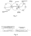
- Fig. 5 schematically illustrates an IP/MPLS network, wherein route filtering is implemented between the core network (core domain) and each one of the access/aggregation networks (access/aggregation domains), as illustrated by the words "Outbound BGP filters" on Fig. 5 .
- the access/aggregation and core domains are separate from an internal BGP (I-BGP) perspective.
- Route filtering is implemented at both autonomous system border router BR 1 and autonomous system border router BR 2 .
- PE to PE connectivity e.g., a hierarchical LSP
- PE to PE connectivity is set up only if there is a VPN that requires that connectivity.
- the loopback IP address of e.g. PE 2 in Fig. 5 may be filtered by BGP e.g. in BR 1 . Due to the BGP filter, there is no hierarchical LSP e.g. from PE 1 to PE 2 by default. This does not allow setting up a VPN service between e.g. PE 1 and PE 2 without manual configuration, i.e. without adjusting the BGP filters.
- Prior art VPN auto-discovery methods may be applied directly in multi-domain IP/MPLS deployments with BGP route filtering (see Fig. 5 ).
- these solutions do not provide means to automate the provisioning of PE to PE connectivity, e.g. hierarchical PE to PE LSPs.
- all PE to PE connectivity has to be set up before the service is created, e.g. without applying any BGP ORFs in the RRs, or by adjusting BGP filters manually.
- the local PE router i.e., the PE router where the VPN was originally configured
- a BGP peer When a BGP peer (intermediate router) receives a request for a new RT, it re-evaluates the advertisement status of NLRIs that match the RT in question and sends the VPN NLRIs corresponding to the RT back to the PE router.
- the PE router however cannot consider the newly received VPN NLRIs because it may not have connectivity, e.g. an LSP, to the BGP next hop of the VPN NLRI.
- LDP Label Distribution Protocol
- Inter-domain LSPs are generally set-up using BGP labelled LSPs (as explained for example in Y. Rekhter et al, "RFC 3107: Carrying Label Information in BGP-4", The Internet Society, Network Working Group, May 2001 ). Such LSPs are also referred as H-LSP.
- BGP advertisements are filtered using routing filters, such as for example ORFs (unless configured manually otherwise).
- ORF outbound routing filters
- the prior art Route Target based BGP auto-discovery method for VPN topology auto-discovery is extended to automate PE to PE connectivity, e.g. MPLS LSP set up. This is useful in network scenarios where there is no full mesh LSP-s between PE nodes by default.
- an intermediate router upon receiving a BGP update, inspects the BGP next hop attribute of the BGP update with VPN layer NLRI and adjusts its own and/or its peers' inbound/outbound route filters corresponding to the IP (v4 or v6) address of the BGP next hop in a way that IP layer reachability information is distributed to BGP speakers according to VPN topologies needs (meaning for example that the intermediate router needs to have an H-LSP to the BGP next-hop of the VPN-IPv4 prefix; H-LSPs to other BGP speakers are not used and can be filtered out).
- a LSP may be established in accordance with a downstream unsolicited mode, so that, if a filter does not prevent it, the LSP is set up automatically.
- a change of filter implies a "soft-reset", i.e. resending the advertised information according to the new filter entries.
- a downstream unsolicited mode involves distributing label bindings to label switching routers (LSRs) that have not explicitly requested them (in that respect, see for example, E. Rosen et al, "RFC 3031: “Multiprotocol Label Switching Architecture", The Internet Society, Network Working Group, January 2001 , section 3.7; or L. Andersson et al, "RFC 3036: LDP Specification", The Internet Society, Network Working Group, January 2001 , section 2.6).
- the IP address of the BGP next hop may for example decoded from the BGP update message with VPN specific NLRI as shown in Fig. 6 .
- the exact method is specific to a given VPN type.
- the next hop consists of a Route Distinguisher field, which is set to zero, and the IP address of the BGP next hop.
- the BGP next hop IP address decoded from a BGP update with VPN layer NLRI is the address of the next hop for the VPN-NLRI.
- an intermediate router after receiving service specific information, asks its BGP neighbour(s) to provide the necessary labelled IP layer reachability information if it does not exist already in the node.
- the method is agnostic to the technology of the service as long as the service distributes routing information via MP-BGP.
- Fig. 7 is a flowchart of a method in one embodiment of the invention (an embodiment of solution A).
- the method is carried out by an intermediate router being an ASBR, an ABR, or a RR.
- the router is a BGP speaker, which stores filtering information to limit the propagation of NLRI.
- the router may for example use constrained route distribution and outbound route filtering (ORF) with its BGP neighbours.
- ORF outbound route filtering
- the intermediate router may maintain a list of next-hop(s) used by its services and may ask its peers to advertise (labelled) IP layer reachability information by building and distributing ORF filter entries that allow distributing the IP addresses of the next-hop(s). Inbound route filtering may also be used.
- the intermediate router receives, from another BGP speaker, a BGP update message comprising NLRI specific to a virtual private network (said NLRI being here referred to as "VPN-NLRI"), and path information comprising an address of a next hop for said VPN-NLRI.
- the address may be an IP address, such as an IPv4 or IPv6 address, but is not limited thereto.
- the method is triggered by the receipt, by the intermediate router, of new VPN NLRI information. This may have resulted from several events at another BGP speaker such as a PE router, such as for example changing imported RT values on a PE router, changes in the network topology, etc.
- step s20 the intermediate router determines whether there is a route to the next hop. In other words, upon receiving a new NLRI for a VPN, the router checks the reachability of the next-hop(s) of the NLRI. If there is no route to the next hop, the method moves to step s30. If there is a route to the next hop (not illustrated on Fig. 7 ), then there is nothing to do. Step s20 of determining may be carried out based on the content of a forwarding information database (FIB) stored on the router, although other routing information databases may be used.
- FIB forwarding information database
- the intermediate router modifies the filtering information so as to permit propagation of NLRI comprising the address of the next hop.
- step s40 the intermediate router sends the modified filtering information to BGP neighbours of the router.
- This step may comprise advertising ORF information to the router's BGP neighbours. Advertising the ORF information to the router's BGP neighbours may be implemented by sending a BGP refresh message to the router's BGP neighbours.
- Step s40 of sending the modified filtering information to BGP neighbours of the router may also be limited to sending the modified filtering information to those BGP neighbours that are configured to store filtering information to limit the propagation of NLRI.
- This method ensures that service related PE to PE connectivity (e.g. hierarchical LSPs) is available and only such hierarchical LSPs are installed in the PE node that is required by the services.
- service related PE to PE connectivity e.g. hierarchical LSPs
- Fig. 8 is a flowchart of a method in one embodiment of the invention (an embodiment of solution B). The method is also carried out by a router being an ASBR, an ABR, or a RR.
- the router is also a BGP speaker, which stores filtering information to limit the propagation of NLRI.
- the router may for example use constrained route distribution and outbound route filtering (ORF) with its BGP neighbours.
- ORF outbound route filtering
- the intermediate router may maintain a list of next-hop(s) used by its services and may ask its peers to advertise (labelled) IP layer reachability information by building and distributing ORF filter entries that allow distributing the IP addresses of the next-hop(s). Inbound route filtering may also be used.
- the intermediate router determines that a BGP update message comprising (i) NLRI specific to a virtual private network (said NLRI being hereinafter referred to as "VPN-NLRI"), and (ii) path information comprising an address (such as an IP address) of a next hop for said VPN-NLRI, is due to be sent by the router to another BGP speaker (BGP peer).
- BGP peer BGP speaker
- step s120 the intermediate router determines whether the filtering information (stored on the intermediate router) allows propagation, to the BGP peer, of NLRI comprising the address of the next-hop. If the filtering information allows propagation (not illustrated on Fig. 7 ), then there is nothing to do. If the filtering information does not allow propagation, the method moves to step s130.
- step s130 the intermediate router modifies the filtering information so as to permit propagation, to the BGP peer, of NLRI comprising the address of the next hop. If the filtering information stored on the router comprises ORF information, step s130 comprises modifying the ORF information associated with the BGP peer.
- step s140 the intermediate router sends the BGP update message to the BGP peer.
- every time a BGP speaker (such as for example BR 1 in Fig. 10 ) is about to send a BGP update message with VPN layer NLRI (step s110), it first checks (step s120) if the ORF filter corresponding to its peer BGP speaker contains the NLRI next hop. If so, it assumes that the peer is already receiving IP layer reachability information and hence, the peer is able to install the VPN route. If no, the BGP speaker modifies the ORF to allow the NLRI next hop (step s130), which will trigger a BGP update message to be sent to the peer with the IP layer reachability information of the NLRI next hop (step s140).
- the BGP peer After step s140, the BGP peer has all the information (including H-LSP related information and VPN-NLRI related information) to be able to forward traffic. The BGP may then evaluate the received information and update its routing table entries (not illustrated on Fig. 8 ).
- the router may be a RR for both the VPN-NLRI and the IP layer routes, and the step of sending s140 the BGP update message to the BGP peer may then comprise sending the BGP update message to the next hop with IP layer reachability information.
- Figs. 7 and 8 are not intended to define the timing and sequence between the BGP decision process (also triggered by the reception of a BGP update message) and the methods of these embodiments.
- the methods of these embodiments do not put any timing or sequence constraint on the BGP decision process. More background about the BGP decision process may for example be found in RFC 4271, section 9.
- Figs. 9 and 10 schematically illustrate two network configurations in which the method of the invention may be put into practice.
- Fig. 9 shows that different BGP RRs may be set up for VPN layer NLRI distribution and for IP (v4 or v6) route distribution.
- RR 1 reflects IP routes and RR 2 reflects VPN NLRI S .
- VPNv4 is the prefix for a VPN-IPv4 address.
- solution A may be carried out by RR 2 in the network configuration illustrated by Fig. 9 .
- Fig. 10 shows that the same RRs may be used to distribute VPN and IP layer routes. This is the case for example if the RRs are in the data path, but the invention is not limited to this configuration.
- the BGP speaker nodes may run a simpler process to automate LSP setup.
- solution A may be carried out by BR 1 , RR 1 and/or BR 2 in the network configuration illustrated by Fig. 10 .
- solution B may be carried out by BR 1 , RR 1 and/or BR 2 in the network configuration illustrated by Fig. 10 .
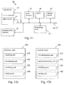
- Fig. 11 is a schematic diagram of an exemplary implementation of a network node 50 that may carry out a method in accordance with embodiments of the invention.
- network node 50 may include a bus 55, a processing unit 53, a main memory 57, a ROM 58, a storage device 59, an input device 52, an output device 54, and a communication interface 56.
- Bus 55 may include a path that permits communication among the components of network node 50.
- Processing unit 53 may include a processor, a microprocessor, or processing logic that may interpret and execute instructions.
- Main memory 57 may include a RAM or another type of dynamic storage device that may store information and instructions for execution by processing unit 53.
- ROM 58 may include a ROM device or another type of static storage device that may store static information and instructions for use by processing unit 53.
- Storage device 59 may include a magnetic and/or optical recording medium and its corresponding drive.
- Input device 52 may include a mechanism that permits an operator to input information to network node 50, such as a keypad, a keyboard, a mouse, a pen, voice recognition and/or biometric mechanisms, etc.
- Output device 54 may include a mechanism that outputs information to the operator, including a display, a printer, a speaker, etc.
- Communication interface 56 may include any transceiver-like mechanism that enables network node 50 to communicate with other devices and/or systems. For example, communication interface 56 may include mechanisms for communicating with another device or system via a network.
- Network node 50 may perform certain operations or processes described herein. These operations may be performed in response to processing unit 53 executing software instructions contained in a computer-readable medium, such as main memory 57, ROM 58, and/or storage device 59.
- a computer-readable medium may be defined as a physical or a logical memory device.
- a logical memory device may include memory space within a single physical memory device or distributed across multiple physical memory devices.
- Each of main memory 57, ROM 58 and storage device 59 may include computer-readable media.
- the magnetic and/or optical recording media (e.g., readable CDs or DVDs) of storage device 59 may also include computer-readable media.
- the software instructions may be read into main memory 57 from another computer-readable medium, such as storage device 59, or from another device via communication interface 56.
- main memory 59 may cause processing unit 53 to perform operations or processes described herein, such as, but not limited to, steps s10, s20, s30, s40, s110, s120, s130, and s140.
- steps s10, s20, s30, s40, s110, s120, s130, and s140 may be used in place of or in combination with software instructions to implement processes and/or operations described herein.
- implementations described herein are not limited to any specific combination of hardware and software.
- Fig. 12a schematically illustrates functional units of a network node 200 according to one embodiment of the invention.
- the network node illustrated on Fig. 12a may for example be implemented as illustrated on Fig. 11 .
- Network node 200 hosts a router function, and has the role of an ASBR, an ABR, and/or a RR.
- Network node 200 is a BGP speaker. It stores filtering information to limit the propagation of NLRI.
- Network node 200 comprises a first unit 210, a second unit 220, a third unit 230, a fourth unit 240 hereinafter referred to as “receiving unit”, “determining unit”, “modifying unit” and “sending unit” respectively.
- Receiving unit 210 is configured for receiving, from another BGP speaker, a BGP update message comprising (i) NLRI specific to a virtual private network, said NLRI being hereinafter referred to as "VPN-NLRI", and (ii) path information comprising an address of a next hop for said VPN-NLRI.
- Determining unit 220 is configured for determining that there is no route to the next hop.
- Modifying unit 230 is configured for modifying the filtering information so as to permit propagation of NLRI comprising the address of the next hop.
- Sending unit 240 is configured for sending the modified filtering information to BGP neighbours of the network node 200.
- Fig. 12b schematically illustrates functional units of a network node 300 according to one embodiment of the invention.
- the network node illustrated on Fig. 12b may for example be implemented as illustrated on Fig. 11 .
- Network node 300 hosts a router function, and has the role of an ASBR, an ABR, and/or a RR.
- Network node 300 is a BGP speaker. It stores filtering information to limit the propagation of NLRI.
- Network node 300 comprises a first unit 310, a second unit 320, a third unit 330, a fourth unit 340 hereinafter referred to as "first determining unit”, “second determining unit”, “modifying unit” and “sending unit” respectively.
- First determining unit 310 is configured for determining that a BGP update message comprising (i) NLRI specific to a virtual private network, said NLRI being hereinafter referred to as "VPN-NLRI", and (ii) path information comprising an address of a next hop for said VPN-NLRI, is due to be sent by the router to another BGP speaker (BGP peer).
- BGP peer BGP speaker
- Second determining unit 320 is configured for determining that the filtering information does not allow propagation, to the BGP peer, of NLRI comprising the address of the next-hop.
- Modifying unit 330 is configured for modifying the filtering information so as to permit propagation, to the BGP peer, of NLRI comprising the address of the next hop.
- Sending unit 340 is configured for sending the BGP update message to the BGP peer.
- Any one of the above-referred units of a network node may be implemented in hardware, software, field-programmable gate array (FPGA), application-specific integrated circuit (ASICs), firmware or the like.
- FPGA field-programmable gate array
- ASICs application-specific integrated circuit
- the above-mentioned and/or claimed receiving unit, determining unit, modifying unit, sending unit, first determining unit and second determining unit are replaced by receiving means, determining means, modifying means, sending means, first determining means and second determining means respectively for performing the functions of the receiving unit, determining unit, modifying unit, sending unit, first determining unit and second determining unit.
- any one of the above-described procedures, steps or processes may be implemented using computer-executable instructions, for example in the form of computer-executable procedures, methods or the like, in any kind of computer languages, and/or in the form of embedded software on firmware, integrated circuits or the like.
Landscapes
- Engineering & Computer Science (AREA)
- Computer Networks & Wireless Communication (AREA)
- Signal Processing (AREA)
- Computer Security & Cryptography (AREA)
- Data Exchanges In Wide-Area Networks (AREA)
Description
- The present invention relates to the field of computer networking and, in particular, to the field of packet-switched networks. In particular, the invention relates to methods, routers, computer programs and computer program products for connectivity setup between provider edge (PE) routers.
- The Border Gateway Protocol (BGP) was originally developed in the late 1980s and at the beginning of the 1990s and has evolved into a widely used, mature protocol for interconnecting network domains, i.e. interconnecting autonomous systems (AS). As of November 2012, the current version of BGP is defined in Y. Rekhter et al, "RFC 4271: A Border Gateway Protocol 4 (BGP-4)", The Internet Society, Network Working Group, January 2006. BGP may for example be used to interconnect network domains operated by different service providers, such as different Internet service providers (ISPs). BGP is a protocol designed to exchange reachability information, i.e. information between routers as to which destination networks are reachable through which routers. BGP is designed to carry information about the path to be traversed by reachability information. The information is carried in a manner suppressing information looping and allowing incremental updates, i.e. sending only the changes in the reachability information, rather than periodically sending all the reachability information to all routers.
- BGP is a path vector protocol. Each entry in a BGP routing table comprises the destination network, the next router, i.e. the next hop, and the path to reach the destination network.
- BGP-capable routers are called BGP speakers. Neighbour BGP speakers are called BGP peers. Two BGP peers communicate with each other through a BGP session. A BGP speaker maintains, for each BGP session, a state variable in accordance with a finite state machine.
- In a so-called full interior BGP mesh, all the reachability information is distributed to all BGP speakers within an AS as well as across autonomous system borders. To do so, within an AS, BGP sessions need to be established between each pair of BGP speakers. In practice, therefore, BGP sessions are established between each pair of border routers of an AS. Such a full-mesh solution is simple in terms of implementation. However, with the growth of the Internet, the size of most AS has significantly increased and, consequently, the size of the full meshes within these AS has significantly increased as well.
- A solution to cope with this problem is route reflection, which involves the distribution of reachability information in accordance with the hub-and-spoke principle. Namely, a router in the AS acts as a hub for the distribution of the reachability information. Such a router is called a router reflector (RR). Route reflection significantly reduces the number of BGP sessions to be established within an AS and therefore leads to more efficient intra-domain connectivity. Furthermore, there may be more than one RR in an AS. Regarding route reflection, see also for example T. Bates et al, "RFC 2796: BGP Route Reflection - An Alternative to Full Mesh IBGP", The Internet Society, Network Working Group, April 2000.
- In order to provide efficient inter-domain connectivity, constraining the distribution of reachability information through route filters may be used. Reachability information is marked and then distributed across the domains, or not, depending on how the reachability information is marked. In other words, reachability information is filtered out based on markers. For example, the use of Route Target (RT) communities enables to specify that, within a particular router, all the reachability information marked as belonging to a particular RT Community should, or should not, be filtered out. A Route Target community is a BGP extended community that conditions network layer reachability information based on virtual private network (VPN) membership, in applications that will now be explained.
- Nowadays, BGP is also used to support other applications than traditional Internet applications, for example to carry reachability information for virtual private networks (VPNs). These developments have been made possible notably because the reachability information carried by BGP is not limited to IPv4 and IPv6 prefixes. In particular, the so-called BGP/MPLS VPNs (also known as 2547 VPNs) and BGP for VPN auto-discovery applications have been developed.
- In the above-mentioned BGP/MPLS VPNs application, BGP is used to distribute VPN reachability information across a provider backbone and Multiprotocol Label Switching (MPLS) is used to transport VPN traffic from one VPN site to another over the provider backbone. The provider backbone may be made of several interconnected domains, each operated by a service provider. For example, E. Rosen et al, "RFC 4364: BGP/MPLS IP Virtual Private Networks (VPNs)", The Internet Society, Network Working Group, February 2006, describes a method by which a service provider may use an Internet Protocol (IP) backbone to provide IP VPNs for its customers. The purpose of a VPN is to maintain privacy of communication and address space. This method will be briefly explained with reference to
Figs. 1 to 4 . -
Fig. 1 schematically illustrates a set of four "sites" (the customer sites) attached to a common network (the IP backbone). The IP backbone, which is owned and/or operated by a service provider, provides an IP service to the customer. For example, a first VPN (VPN1) may involvecustomer sites customer sites - The customer may attach to the backbone via a
layer 2 service, but thelayer 2 service is terminated at the "edge" of the backbone, where the customer's IP datagrams are removed from anylayer 2 encapsulation, as schematically illustrated byFig. 2 . - As explained in RFC 4364, section 1.2, first paragraph, at the edge of a backbone, routers "can be attached to each other, or to end systems, in a variety of different ways: PPP connections, ATM Virtual Circuits (VCs), Frame Relay VCs, ethernet interfaces, Virtual Local Area Networks (VLANs) on ethernet interfaces, GRE tunnels,
Layer 2 Tunneling Protocol (L2TP) tunnels, IPsec tunnels, etc." The term "attachment circuit" refers to the means of attaching to a router, as schematically illustrated inFig. 3 , so that two devices can be network layer peers over the attachment circuit. - In that context, and still referring to
Fig. 3 , each VPN site, i.e.customer sites 1 to 4, comprises at least one customer edge (CE) devices (although a customer site may be involved in more than one VPN). For example, CE device CE1 belongs tocustomer site 1, CE device CE2 belongs tocustomer site 2, etc. Each CE device is attached, through an attachment circuit, to one or more provider edge (PE) routers. For example, CE device CE1 is attached to PE router PE1, CE device CE2 is attached to PE router PE2, etc. Routers in the service provider's network (i.e., in the backbone) that do not attach to CE devices are known as P routers. - BGP is used by the service provider to exchange the reachability information, also called simply routes, of a particular VPN among the PE routers that are attached to that VPN. In BGP, a route is a unit of information that pairs a set of destinations with the attributes of a path to those destinations. The set of destinations are systems whose IP addresses are contained in one IP address prefix carried in the network layer reachability information (NLRI) field of a BGP update message. The path is the information reported in the path attributes field of the same BGP update message (RFC 4271, section 1.1). Routes are advertised between BGP speakers in update messages.
- As explained in RFC 4364, BGP is used by the service provider to exchange the routes of a particular VPN among the PE routers that are attached to that VPN in a manner that ensures that routes from different VPNs remain distinct and separate, even though two VPNs may have an overlapping address space. Each route within a VPN is assigned a MPLS label. When BGP distributes a VPN route, it also distributes an MPLS label for that route. The PE routers distribute, to the CE routers in a particular VPN, the routes from other CE routers in that VPN. In such a manner, user data packets can be tunnelled through the service provider backbone, after having been encapsulated with the MPLS label corresponding to the customer's VPN and further encapsulated so that the packets is tunnelled across the service provider backbone to the proper PE router.
- RFC 4364, section 4.3.2, explains how routes may be distributed among PE routers. Namely, if two sites of a VPN attached to PE routers that are in the same AS, the PE routers can distribute VPN-IPv4 routes to each other by means of a BGP connection between them. Alternatively, each can have an IBGP connection to a route reflector (RR), as explained above.
- The same principles apply to the case of a multi-provider backbone, as schematically illustrated by
Fig. 4 . An autonomous system border router (ASBR) is a router located at the border between two AS operated by different service providers. - Furthermore, in the above-mentioned BGP for VPN auto-discovery application, BGP can be used so that a VPN can auto-discover its members in the sense that the set of PE routers having a VPN in common is identified. In other words, BGP is used to auto-discover the end points of a VPN. Instead of configuring a PE router with information about all the other PE routers of a given VPN, the PE router uses BGP to discover the other PE routers. Using Route Targets, the PE router announces to its BGP neighbours that it belongs to a particular VPN.
- Regarding VPN auto-discovery using BGP, see for example K. Kompella et al, "RFC 4761: Virtual Private LAN Service (VPLS), Using BGP forAuto-Discovery and Signaling", The IETF Trust, Network Working Group, January 2007 (notably section 3.1), and K. Kompella et al, "RFC 6624: .
- IEEE document "A new VPN routing approach for large scale networks" from Zied Ben Houidi et al (pages 124 - 133), October 05, 2010 (ISBN: 978-1-4244-8644-1) discloses that BGP is not appropriate for large scale VPN routing because it causes some routers to keep state for all routes in the network. The authors of this document propose a Two-step-VPN routing, an End-to-End signalling approach in which two concerns are separated: the creation of VPN topology and the advertisement of VPN site reachability. End-to-End signalling guarantees that no router will have to maintain the full state and that no path exploration will happen; the separation of topology and reachability allow to scale the End-to-End signalling.
-
US 7 787 396 B1 discloses a method, apparatus and computer program product for providing Outbound Route Filtering (ORF). An ORF list is produced and an ORF filter is built from the ORF list. The ORF list is built from received ORF entries. The ORF list is advertised to client and non-client peers. The ORF filter is built from a received ORF list and is directed toward the advertiser of the ORF list. - It is desirable to improve the methods for setting up connectivity between PE routers of VPN(s) provided over a backbone, with in mind the need to reduce the provisioning burden on the service provider(s). This aim should be met without increasing, or at least without excessively increasing, the implementation and architecture complexity and the associated equipment costs.
- To meet or at least partially meet the above-mentioned goals, methods, network nodes, and computer program product according to the invention are defined in the independent claims. Advantageous embodiments are defined in the dependent claims.
- In one embodiment (hereinafter referred to as "solution A"), a method is carried out by a router, the router being at least one of an autonomous system border router (ASBR), an area border router (ABR), and a route reflector (RR). The router is also a BGP speaker. The router stores filtering information to limit the propagation of network layer reachability information (NLRI). At one point in time, the router receives, from another BGP speaker, a BGP update message comprising (i) NLRI specific to a virtual private network (VPN) (said NLRI being hereinafter referred to as "VPN-NLRI"), and (ii) path information comprising an address of a next hop for said VPN-NLRI. The router determines that there is no route established to the next hop. Then, the router modifies the filtering information (i.e., the filtering information stored on the router) so as to permit propagation of NLRI comprising the address of the next hop, and the router sends the modified filtering information to BGP neighbours of the router.
- In another embodiment (hereinafter referred to as "solution B"), a method is carried out by a router which is also at least one of an ASBR, an ABR, and a RR. The router is also a BGP speaker and it stores filtering information to limit the propagation of NLRI. In solution B, the router determines that a BGP update message comprising (i) NLRI specific to a VPN (said NLRI being likewise hereinafter referred to as "VPN-NLRI"), and (ii) path information comprising an address of a next hop for said VPN-NLRI, is due to be sent by the router to another BGP speaker (hereinafter referred to as "BGP peer"). The router however determines that the filtering information (i.e., the filtering information stored on the router) does not allow propagation, to the BGP peer, of NLRI comprising the address of the next-hop. The router then modifies the filtering information so as to permit propagation, to the BGP peer, of NLRI comprising the address of the next hop; and the router sends the BGP update message to the BGP peer.
- The two above-described solutions A and B constitute alternative solutions to the same particular problem of efficiently setting up connectivity between PE routers.
- Namely, an intermediate router (i.e., an ASBR, an ABR, and/or a RR) of a backbone network (or of set of interconnected networks) faces a situation where the configuration and/or filtering information (such as well-known outbound or inbound routing filters, and more generally any filtering information according to the concept of constrained distribution of reachability/routing information) prevents the router from transferring reachability/routing information to its BGP neighbours (or some of them).
- To solve the problem faced by the intermediate router, a manual reconfiguration (i.e., operator-controlled provisioning) of the filtering information on the intermediate router would be required. This is impractical. The invention proposes that the intermediate router be capable of reconfiguring itself to modify, when necessary, the filtering information stored on the router to override the existing filtering information and therefore to gradually populate the filtering information to permit propagation of NLRI pertaining to some desired VPNs to be quickly implemented on the provider backbone, without requiring any operator-controlled provisioning to define which propagation is permitted as part of the filtering information. The invention covers the cases where a determination (i.e., the detection of the "obstacle" preventing the router from transferring reachability/routing information to its BGP neighbours or some of them) is made based either (i) on the absence of any established route from the router to an announced next hop (solution A, for example involving consulting the router's forwarding information database) or (ii) on the actual filtering information stored on the router (solution B, for example involving consulting one of the router's existing ORFs).
- In solution A, the method is always triggered by a received BGP update message. The intermediate router receives the VPN-NLRI and path information, checks whether there is a route established to the next-hop, updates its filter information if necessary, and sends the filter information to its BGP neighbours (or some of them). The BGP neighbours are responsible for the next-hop information propagation.
- In solution B, the method is triggered by a situation where a BGP update message is due to be sent to a BGP peer, for example because a BGP update message has been received or for other reasons (e.g. manual reconfiguration, change of topology affecting the intermediate router, etc.). When the intermediate router is about to send a VPN-NLRI and path information, it modifies the filtering information if necessary and sends the BGP update message to the BGP peer.
- The invention, and its two alternative solutions, therefore addresses the problem that prior art BGP VPN auto-discovery methods do not cover the automation of PE router to PE router connectivity setup. This problem arises from the assumption that the PE router to PE router connectivity, such as for example using label-switched paths (LSP), would be already set up beforehand, because there would a full mesh of connectivity, such as for example through LSPs, between PE routers.
- In large scale IP/MPLS scenarios however, this is not the case, and filtering of BGP propagated information (for example based on RT communities) is implemented in order to keep BGP tables in some nodes small, e.g. access network devices. In such scenarios, PE to PE connectivity (e.g. a hierarchical LSP) is set up only if there is a VPN that requires that connectivity. Prior art systems do not allow setting up connectivity between two PE routers dynamically. Prior art systems require a proper configuration of the BGP filters of the intermediate routers at the outset or a manual configuration thereof, when necessary.
- The invention provides means to automate the provisioning of PE to PE connectivity, such as for example hierarchical PE to PE LSPs. This is useful in network scenarios involving intermediate routers, where there is no full connectivity mesh between PE routers by default. The solutions proposed by the invention ensure that PE to PE connectivity (e.g. hierarchical LSPs) is available and only such connectivity is installed in the intermediate routers that is required by the services. Connectivity is gradually established within the intermediate routers, thus avoiding the need to have, by default, large filtering tables stored on the intermediate routers.
- In the above context, an area border router (ABR) is a router that is connected to a plurality of areas of an Open Shortest Path First (OSPF) network within a single AS.
- For more information about OSPF, see for example J. Moy et al, "RFC 2328: . A router may be both an ABR and ASBR at the same time.
- The term "next hop" generally refers to the next router along a network path to a destination. Within a BGP update message, the next hop may be specified as a path attribute to define the address of the router to be used as the next router on the path to the destinations listed in the NLRI field of said BGP update message (see for example RFC 4271, section 5.1.3).
- Regarding constrained route distribution and route filtering, see for example P. Marques et al, "RFC 4684: Constrained Route Distribution for Border Gateway Protocol/MultiProtocol Label Switching (BGP/MPLS) Internet Protocol (IP) Virtual Private Networks (VPNs)", The IETF Trust, Network Working Group, November 2006; E. Chen et al, "RFC 5291: Outbound Route Filtering Capability for BGP-4", IETF, Network Working Group, August 2008; and E. Chen et al, "RFC 5292: Address-Prefix-Based Outbound Route Filter for BGP-4", I ETF, Network Working Group, August 2008, although the invention is not limited to these constrained route distribution and route filtering mechanisms. RFC 4684 notably defines MultiProtocol BGP (MP-BGP) procedures that allow BGP speakers to exchange Route Target reachability information. This information can be used to build a route distribution graph in order to limit the propagation of Virtual Private Network (VPN) Network Layer Reachability Information (NLRI) between different autonomous systems or distinct clusters of the same AS. According to RFC 5291, outbound route filtering "allows a BGP speaker to send to its BGP peer a set of Outbound Route Filters (ORFs) that the peer would use to constrain/filter its outbound routing updates to the speaker". This enables a router to discard BGP updates which are not in the ORF, i.e. discarding unwanted updates (to save resources). This is useful in a VPN in which a subset of CE devices is not involved at all in the routes in the VPN (the subset is not attached to the VPN). RFC 5292 "defines a new Outbound Router Filter (ORF) type for BGP that can be used to perform address-prefix-based route filtering". Namely, the CE devices communicate to the PE router prefix-based outbound routing filtering to transmit only a subset of routes.
- The invention also relates to network nodes implementing routing functions (i.e., routers) and comprising functional units and/or computer-executable instructions configured for carrying out the above-mentioned methods.
- The invention also relates to a computer program product comprising computer-executable instructions configured, when executed on a network node or on a computer, to cause the network node or the computer to carry out a method according to any one of the above-described embodiments.
- Embodiments of the present invention shall now be described, in conjunction with the appended figures, in which:
-
Fig. 1 schematically illustrates four customer sites and a service provider backbone, to explain the background of the invention; -
Fig. 2 schematically illustrates four customer sites and a service provider backbone, as well as the process occurring at the edge of the backbone, to explain the background of the invention; -
Fig. 3 schematically illustrates four customer sites and a service provider backbone, along with the CE devices and PE routers attached to each other, to explain the background of the invention; -
Fig. 4 schematically illustrates four customer sites and a multi-provider backbone, to explain the background of the invention; -
Fig. 5 schematically illustrates two access/aggregation networks and a core network with PE to PE connectivity established over them, to explain some of the problems that some embodiments of the invention solve; -
Fig. 6 schematically illustrates a BGP update message syntax; -
Fig. 7 is a flowchart of a method according to one embodiment (an embodiment of solution A) of the invention; -
Fig. 8 is a flowchart of a method according to one embodiment (an embodiment of solution B) of the invention; -
Figs. 9 and 10 schematically illustrate two network configurations in which the method of the invention may be put into practice; -
Fig. 11 schematically illustrates a possible implementation of a network node which may be used in one embodiment of the invention; and -
Figs. 12a and 12b schematically illustrate two network nodes in accordance with two embodiments of the invention respectively. - The present invention shall now be described in conjunction with specific embodiments. These specific embodiments serve to provide the skilled person with a better understanding, but are not intended to in any way restrict the scope of the invention, which is defined by the appended claims.
- To explain the problems that some embodiments of the invention solve,
Fig. 5 schematically illustrates an IP/MPLS network, wherein route filtering is implemented between the core network (core domain) and each one of the access/aggregation networks (access/aggregation domains), as illustrated by the words "Outbound BGP filters" onFig. 5 . The access/aggregation and core domains are separate from an internal BGP (I-BGP) perspective. Route filtering is implemented at both autonomous system border router BR1 and autonomous system border router BR2. In this network, PE to PE connectivity (e.g., a hierarchical LSP) is set up only if there is a VPN that requires that connectivity. - In particular, the loopback IP address of e.g. PE2 in
Fig. 5 may be filtered by BGP e.g. in BR1. Due to the BGP filter, there is no hierarchical LSP e.g. from PE1 to PE2 by default. This does not allow setting up a VPN service between e.g. PE1 and PE2 without manual configuration, i.e. without adjusting the BGP filters. - The same problem exists also for services spanning the network of multiple operators, e.g. in case of inter AS VPN option C (see RFC 4364, page 32).
- Prior art VPN auto-discovery methods may be applied directly in multi-domain IP/MPLS deployments with BGP route filtering (see
Fig. 5 ). However, as explained above, these solutions do not provide means to automate the provisioning of PE to PE connectivity, e.g. hierarchical PE to PE LSPs. Thus, all PE to PE connectivity has to be set up before the service is created, e.g. without applying any BGP ORFs in the RRs, or by adjusting BGP filters manually. At VPN creation, the local PE router (i.e., the PE router where the VPN was originally configured) distributes its new Route Target reachability information. When a BGP peer (intermediate router) receives a request for a new RT, it re-evaluates the advertisement status of NLRIs that match the RT in question and sends the VPN NLRIs corresponding to the RT back to the PE router. The PE router however cannot consider the newly received VPN NLRIs because it may not have connectivity, e.g. an LSP, to the BGP next hop of the VPN NLRI. - In other words, the PE router cannot create an LSP to the BGP next hop of the VPN NLRI. Label Distribution Protocol (LDP) cannot be used. Inter-domain LSPs are generally set-up using BGP labelled LSPs (as explained for example in Y. Rekhter et al, "RFC 3107: Carrying Label Information in BGP-4", The Internet Society, Network Working Group, May 2001). Such LSPs are also referred as H-LSP. However, in order to protect the resources of the routers in the access/aggregation domain, BGP advertisements are filtered using routing filters, such as for example ORFs (unless configured manually otherwise). In other words, the communication between BGP speakers is constrained by routing filters, such as for example outbound routing filters (ORF) which are by default not allowing any BGP-speaker-to-BGP-speaker communication (unless configured manually otherwise).
- In one embodiment of the invention, the prior art Route Target based BGP auto-discovery method for VPN topology auto-discovery is extended to automate PE to PE connectivity, e.g. MPLS LSP set up. This is useful in network scenarios where there is no full mesh LSP-s between PE nodes by default. Namely, in one solution according to the invention, upon receiving a BGP update, an intermediate router (being a BGP speaker) inspects the BGP next hop attribute of the BGP update with VPN layer NLRI and adjusts its own and/or its peers' inbound/outbound route filters corresponding to the IP (v4 or v6) address of the BGP next hop in a way that IP layer reachability information is distributed to BGP speakers according to VPN topologies needs (meaning for example that the intermediate router needs to have an H-LSP to the BGP next-hop of the VPN-IPv4 prefix; H-LSPs to other BGP speakers are not used and can be filtered out).
- Once the routing filter(s) have been adjusted (i.e. modified), a LSP may be established in accordance with a downstream unsolicited mode, so that, if a filter does not prevent it, the LSP is set up automatically. A change of filter implies a "soft-reset", i.e. resending the advertised information according to the new filter entries. A downstream unsolicited mode involves distributing label bindings to label switching routers (LSRs) that have not explicitly requested them (in that respect, see for example, E. Rosen et al, "RFC 3031: "Multiprotocol Label Switching Architecture", The Internet Society, Network Working Group, January 2001, section 3.7; or L. Andersson et al, "RFC 3036: LDP Specification", The Internet Society, Network Working Group, January 2001, section 2.6).
- The IP address of the BGP next hop may for example decoded from the BGP update message with VPN specific NLRI as shown in
Fig. 6 . The exact method is specific to a given VPN type. For example, for VPN-IPv4, the next hop consists of a Route Distinguisher field, which is set to zero, and the IP address of the BGP next hop. The BGP next hop IP address decoded from a BGP update with VPN layer NLRI is the address of the next hop for the VPN-NLRI. - In one embodiment of the invention, an intermediate router, after receiving service specific information, asks its BGP neighbour(s) to provide the necessary labelled IP layer reachability information if it does not exist already in the node. The method is agnostic to the technology of the service as long as the service distributes routing information via MP-BGP.
-
Fig. 7 is a flowchart of a method in one embodiment of the invention (an embodiment of solution A). The method is carried out by an intermediate router being an ASBR, an ABR, or a RR. The router is a BGP speaker, which stores filtering information to limit the propagation of NLRI. The router may for example use constrained route distribution and outbound route filtering (ORF) with its BGP neighbours. In other words, the filtering information stored on the router may comprise ORF information. The intermediate router may maintain a list of next-hop(s) used by its services and may ask its peers to advertise (labelled) IP layer reachability information by building and distributing ORF filter entries that allow distributing the IP addresses of the next-hop(s). Inbound route filtering may also be used. - In step s10, the intermediate router receives, from another BGP speaker, a BGP update message comprising NLRI specific to a virtual private network (said NLRI being here referred to as "VPN-NLRI"), and path information comprising an address of a next hop for said VPN-NLRI. The address may be an IP address, such as an IPv4 or IPv6 address, but is not limited thereto. In other words, the method is triggered by the receipt, by the intermediate router, of new VPN NLRI information. This may have resulted from several events at another BGP speaker such as a PE router, such as for example changing imported RT values on a PE router, changes in the network topology, etc.
- In step s20, the intermediate router determines whether there is a route to the next hop. In other words, upon receiving a new NLRI for a VPN, the router checks the reachability of the next-hop(s) of the NLRI. If there is no route to the next hop, the method moves to step s30. If there is a route to the next hop (not illustrated on
Fig. 7 ), then there is nothing to do. Step s20 of determining may be carried out based on the content of a forwarding information database (FIB) stored on the router, although other routing information databases may be used. - In step s30, the intermediate router modifies the filtering information so as to permit propagation of NLRI comprising the address of the next hop.
- Then, in step s40, the intermediate router sends the modified filtering information to BGP neighbours of the router. This step may comprise advertising ORF information to the router's BGP neighbours. Advertising the ORF information to the router's BGP neighbours may be implemented by sending a BGP refresh message to the router's BGP neighbours. Step s40 of sending the modified filtering information to BGP neighbours of the router may also be limited to sending the modified filtering information to those BGP neighbours that are configured to store filtering information to limit the propagation of NLRI.
- This method ensures that service related PE to PE connectivity (e.g. hierarchical LSPs) is available and only such hierarchical LSPs are installed in the PE node that is required by the services.
-
Fig. 8 is a flowchart of a method in one embodiment of the invention (an embodiment of solution B). The method is also carried out by a router being an ASBR, an ABR, or a RR. The router is also a BGP speaker, which stores filtering information to limit the propagation of NLRI. The router may for example use constrained route distribution and outbound route filtering (ORF) with its BGP neighbours. In other words, the filtering information stored on the router may comprise ORF information. The intermediate router may maintain a list of next-hop(s) used by its services and may ask its peers to advertise (labelled) IP layer reachability information by building and distributing ORF filter entries that allow distributing the IP addresses of the next-hop(s). Inbound route filtering may also be used. - In step s110, the intermediate router determines that a BGP update message comprising (i) NLRI specific to a virtual private network (said NLRI being hereinafter referred to as "VPN-NLRI"), and (ii) path information comprising an address (such as an IP address) of a next hop for said VPN-NLRI, is due to be sent by the router to another BGP speaker (BGP peer).
- In step s120, the intermediate router determines whether the filtering information (stored on the intermediate router) allows propagation, to the BGP peer, of NLRI comprising the address of the next-hop. If the filtering information allows propagation (not illustrated on
Fig. 7 ), then there is nothing to do. If the filtering information does not allow propagation, the method moves to step s130. - In step s130, the intermediate router modifies the filtering information so as to permit propagation, to the BGP peer, of NLRI comprising the address of the next hop. If the filtering information stored on the router comprises ORF information, step s130 comprises modifying the ORF information associated with the BGP peer.
- Then, in step s140, the intermediate router sends the BGP update message to the BGP peer.
- In other words, in one embodiment, every time a BGP speaker (such as for example BR1 in
Fig. 10 ) is about to send a BGP update message with VPN layer NLRI (step s110), it first checks (step s120) if the ORF filter corresponding to its peer BGP speaker contains the NLRI next hop. If so, it assumes that the peer is already receiving IP layer reachability information and hence, the peer is able to install the VPN route. If no, the BGP speaker modifies the ORF to allow the NLRI next hop (step s130), which will trigger a BGP update message to be sent to the peer with the IP layer reachability information of the NLRI next hop (step s140). - After step s140, the BGP peer has all the information (including H-LSP related information and VPN-NLRI related information) to be able to forward traffic. The BGP may then evaluate the received information and update its routing table entries (not illustrated on
Fig. 8 ). - The router may be a RR for both the VPN-NLRI and the IP layer routes, and the step of sending s140 the BGP update message to the BGP peer may then comprise sending the BGP update message to the next hop with IP layer reachability information.
-
Figs. 7 and 8 are not intended to define the timing and sequence between the BGP decision process (also triggered by the reception of a BGP update message) and the methods of these embodiments. The methods of these embodiments do not put any timing or sequence constraint on the BGP decision process. More background about the BGP decision process may for example be found in RFC 4271, section 9. -
Figs. 9 and 10 schematically illustrate two network configurations in which the method of the invention may be put into practice. -
Fig. 9 shows that different BGP RRs may be set up for VPN layer NLRI distribution and for IP (v4 or v6) route distribution. For example RR1 reflects IP routes and RR2 reflects VPN NLRIS. OnFig. 9 , VPNv4 is the prefix for a VPN-IPv4 address. For example, solution A may be carried out by RR2 in the network configuration illustrated byFig. 9 . -
Fig. 10 shows that the same RRs may be used to distribute VPN and IP layer routes. This is the case for example if the RRs are in the data path, but the invention is not limited to this configuration. In this network configuration, the BGP speaker nodes may run a simpler process to automate LSP setup. For example, solution A may be carried out by BR1, RR1 and/or BR2 in the network configuration illustrated byFig. 10 . As another example, solution B may be carried out by BR1, RR1 and/or BR2 in the network configuration illustrated byFig. 10 . -
Fig. 11 is a schematic diagram of an exemplary implementation of a network node 50 that may carry out a method in accordance with embodiments of the invention. As illustrated, network node 50 may include a bus 55, aprocessing unit 53, amain memory 57, aROM 58, astorage device 59, aninput device 52, anoutput device 54, and acommunication interface 56. Bus 55 may include a path that permits communication among the components of network node 50. - Processing
unit 53 may include a processor, a microprocessor, or processing logic that may interpret and execute instructions.Main memory 57 may include a RAM or another type of dynamic storage device that may store information and instructions for execution by processingunit 53.ROM 58 may include a ROM device or another type of static storage device that may store static information and instructions for use by processingunit 53.Storage device 59 may include a magnetic and/or optical recording medium and its corresponding drive. -
Input device 52 may include a mechanism that permits an operator to input information to network node 50, such as a keypad, a keyboard, a mouse, a pen, voice recognition and/or biometric mechanisms, etc.Output device 54 may include a mechanism that outputs information to the operator, including a display, a printer, a speaker, etc.Communication interface 56 may include any transceiver-like mechanism that enables network node 50 to communicate with other devices and/or systems. For example,communication interface 56 may include mechanisms for communicating with another device or system via a network. - Network node 50 may perform certain operations or processes described herein. These operations may be performed in response to processing
unit 53 executing software instructions contained in a computer-readable medium, such asmain memory 57,ROM 58, and/orstorage device 59. A computer-readable medium may be defined as a physical or a logical memory device. For example, a logical memory device may include memory space within a single physical memory device or distributed across multiple physical memory devices. Each ofmain memory 57,ROM 58 andstorage device 59 may include computer-readable media. The magnetic and/or optical recording media (e.g., readable CDs or DVDs) ofstorage device 59 may also include computer-readable media. The software instructions may be read intomain memory 57 from another computer-readable medium, such asstorage device 59, or from another device viacommunication interface 56. - The software instructions contained in
main memory 59 may cause processingunit 53 to perform operations or processes described herein, such as, but not limited to, steps s10, s20, s30, s40, s110, s120, s130, and s140. Alternatively, hardwired circuitry may be used in place of or in combination with software instructions to implement processes and/or operations described herein. Thus, implementations described herein are not limited to any specific combination of hardware and software. -
Fig. 12a schematically illustrates functional units of anetwork node 200 according to one embodiment of the invention. The network node illustrated onFig. 12a may for example be implemented as illustrated onFig. 11 .Network node 200 hosts a router function, and has the role of an ASBR, an ABR, and/or a RR.Network node 200 is a BGP speaker. It stores filtering information to limit the propagation of NLRI. -
Network node 200 comprises afirst unit 210, asecond unit 220, athird unit 230, afourth unit 240 hereinafter referred to as "receiving unit", "determining unit", "modifying unit" and "sending unit" respectively. - Receiving
unit 210 is configured for receiving, from another BGP speaker, a BGP update message comprising (i) NLRI specific to a virtual private network, said NLRI being hereinafter referred to as "VPN-NLRI", and (ii) path information comprising an address of a next hop for said VPN-NLRI. - Determining
unit 220 is configured for determining that there is no route to the next hop. - Modifying
unit 230 is configured for modifying the filtering information so as to permit propagation of NLRI comprising the address of the next hop. - Sending
unit 240 is configured for sending the modified filtering information to BGP neighbours of thenetwork node 200. -
Fig. 12b schematically illustrates functional units of anetwork node 300 according to one embodiment of the invention. The network node illustrated onFig. 12b may for example be implemented as illustrated onFig. 11 .Network node 300 hosts a router function, and has the role of an ASBR, an ABR, and/or a RR.Network node 300 is a BGP speaker. It stores filtering information to limit the propagation of NLRI. -
Network node 300 comprises afirst unit 310, asecond unit 320, athird unit 330, afourth unit 340 hereinafter referred to as "first determining unit", "second determining unit", "modifying unit" and "sending unit" respectively. - First determining
unit 310 is configured for determining that a BGP update message comprising (i) NLRI specific to a virtual private network, said NLRI being hereinafter referred to as "VPN-NLRI", and (ii) path information comprising an address of a next hop for said VPN-NLRI, is due to be sent by the router to another BGP speaker (BGP peer). - Second determining
unit 320 is configured for determining that the filtering information does not allow propagation, to the BGP peer, of NLRI comprising the address of the next-hop. - Modifying
unit 330 is configured for modifying the filtering information so as to permit propagation, to the BGP peer, of NLRI comprising the address of the next hop. - Sending
unit 340 is configured for sending the BGP update message to the BGP peer. - Where the term "receiving unit", "determining unit", "modifying unit", "sending unit", "first determining unit" and "second determining unit" are used herewith, no restriction is made regarding how distributed this element may be and regarding how gathered elements may be. That is, the constituent elements of a unit may be distributed in different software or hardware components or devices for bringing about the intended function. A plurality of distinct elements may also be gathered for providing the intended functionalities.
- Any one of the above-referred units of a network node may be implemented in hardware, software, field-programmable gate array (FPGA), application-specific integrated circuit (ASICs), firmware or the like.
- In further embodiments of the invention, the above-mentioned and/or claimed receiving unit, determining unit, modifying unit, sending unit, first determining unit and second determining unit are replaced by receiving means, determining means, modifying means, sending means, first determining means and second determining means respectively for performing the functions of the receiving unit, determining unit, modifying unit, sending unit, first determining unit and second determining unit.
- In further embodiments of the invention, any one of the above-described procedures, steps or processes may be implemented using computer-executable instructions, for example in the form of computer-executable procedures, methods or the like, in any kind of computer languages, and/or in the form of embedded software on firmware, integrated circuits or the like.
- Although the present invention has been described on the basis of detailed examples, the detailed examples only serve to provide the skilled person with a better understanding, and are not intended to limit the scope of the invention. The scope of the invention is much rather defined by the appended claims.
Claims (14)
- Method, carried out by a router, whereinthe router is at least one of an autonomous system border router, an area border router, and a route reflector,the router is also a Border Gateway Protocol, hereinafter abbreviated as "BGP", speaker; andthe router stores filtering information to limit the propagation of network layer reachability information, hereinafter abbreviated as "NLRI";the method comprising:receiving (s10), from another BGP speaker, a BGP update message comprisingNLRI specific to a virtual private network, said NLRI being hereinafter referred to as "VPN-NLRI", andpath information comprising an address of a next hop for said VPN-NLRI;determining (s20) that there is no route to the next hop; modifying (s30) the filtering information so as to permit propagation of NLRI comprising the address of the next hop; andsending (s40) the modified filtering information to BGP neighbours of the router.
- Method of claim 1, wherein the filtering information stored on the router comprises outbound route filtering information.
- Method of claim 2, wherein the step of sending (s40) the modified filtering information to BGP neighbours of the router comprises advertising the outbound route filtering information to the router's BGP neighbours.
- Method of claim 3, wherein the step of advertising the outbound route filtering information to the router's BGP neighbours comprises:sending a BGP refresh message to the router's BGP neighbours.
- Method according to any one of the preceding claims, wherein the step (s40) of sending the modified filtering information to BGP neighbours of the router comprises:sending the modified filtering information to those BGP neighbours that are configured to store filtering information to limit the propagation of NLRI.
- Method according to any one of the preceding claims, wherein the address of the next hop is an Internet Protocol, hereinafter abbreviated as "IP", address.
- Method according to any one of the preceding claims, wherein the step (s20) of determining that there is no route to the next hop is carried out based on the content of a forwarding information database stored on the router.
- Method, carried out by a router, whereinthe router is at least one of an autonomous system border router, an area border router, and a route reflector,the router is also a Border Gateway Protocol, hereinafter abbreviated as "BGP", speaker; andthe router stores filtering information to limit the propagation of network layer reachability information, hereinafter abbreviated as "NLRI";the method comprising:determining (s110) that a BGP update message comprisingis due to be sent by the router to another BGP speaker, hereinafter referred to as "BGP peer";NLRI specific to a virtual private network, said NLRI being hereinafter referred to as "VPN-NLRI", andpath information comprising an address of a next hop for said VPN-NLRI;determining (s120) that the filtering information does not allow propagation, to the BGP peer, of NLRI comprising the address of the next-hop;modifying (s130) the filtering information so as to permit propagation, to the BGP peer, of NLRI comprising the address of the next hop; andsending (s140) the BGP update message to the BGP peer.
- Method of claim 8, whereinthe filtering information stored on the router comprises outbound route filtering information; andthe step (s130) of modifying the filtering information so as to permit propagation, to the BGP peer, of NLRI comprising the address of the next hop comprises modifying the outbound route filtering information associated with the BGP peer.
- Method of claims 8 or 9, wherein the address of the next hop is an Internet Protocol, hereinafter abbreviated as "IP", address.
- Method of claim 10, whereinthe router is a route reflector for both the VPN-NLRI and the IP layer routes, andsending (s140) the BGP update message to the BGP peer comprises sending the BGP update message to the next hop with IP layer reachability information.
- Network node (200) for hosting a router function, whereinthe network node (200) is at least one of an autonomous system border router, an area border router, and a route reflector,the network node (200) is also a Border Gateway Protocol, hereinafter abbreviated as "BGP", speaker; andthe network node (200) stores filtering information to limit the propagation of network layer reachability information, hereinafter abbreviated as "NLRI";the network node comprising:a receiving unit (210) configured for receiving, from another BGP speaker, a BGP update message comprisingNLRI specific to a virtual private network, said NLRI being hereinafter referred to as "VPN-NLRI", andpath information comprising an address of a next hop for said VPN-NLRI;a determining unit (220) configured for determining that there is no route to the next hop;a modifying unit (230) configured for modifying the filtering information so as to permit propagation of NLRI comprising the address of the next hop; anda sending unit (240) configured for sending the modified filtering information to BGP neighbours of the network node (200).
- Network node (300) for hosting a router function, whereinthe network node (300) is at least one of an autonomous system border router, an area border router, and a route reflector,the network node (300) is also a Border Gateway Protocol, hereinafter abbreviated as "BGP", speaker; andthe network node (300) stores filtering information to limit the propagation of network layer reachability information, hereinafter abbreviated as "NLRI";the network node (300) comprising:a first determining unit (310) configured for determining that a BGP update message comprisingNLRI specific to a virtual private network, said NLRI being hereinafter referred to as "VPN-NLRI", andpath information comprising an address of a next hop for said VPN-NLRI;is due to be sent by the router to another BGP speaker, hereinafter referred to as "BGP peer";a second determining unit (320) configured for determining that the filtering information does not allow propagation, to the BGP peer, of NLRI comprising the address of the next-hop;a modifying unit (330) configured for modifying the filtering information so as to permit propagation, to the BGP peer, of NLRI comprising the address of the next hop; anda sending unit (340) configured for sending the BGP update message to the BGP peer.
- Computer program product comprising computer-executable instructions configured, when executed on a computer, to cause the computer to carry out all the steps of the method according to any one of claims 1 to 11.
Applications Claiming Priority (1)
| Application Number | Priority Date | Filing Date | Title |
|---|---|---|---|
| PCT/EP2012/073704 WO2014082656A1 (en) | 2012-11-27 | 2012-11-27 | Methods and routers for connectivity setup between provider edge routers |
Publications (2)
| Publication Number | Publication Date |
|---|---|
| EP2926507A1 EP2926507A1 (en) | 2015-10-07 |
| EP2926507B1 true EP2926507B1 (en) | 2016-06-01 |
Family
ID=47290948
Family Applications (1)
| Application Number | Title | Priority Date | Filing Date |
|---|---|---|---|
| EP12795403.0A Active EP2926507B1 (en) | 2012-11-27 | 2012-11-27 | Methods and routers for connectivity setup between provider edge routers |
Country Status (3)
| Country | Link |
|---|---|
| US (1) | US9621378B2 (en) |
| EP (1) | EP2926507B1 (en) |
| WO (1) | WO2014082656A1 (en) |
Families Citing this family (22)
| Publication number | Priority date | Publication date | Assignee | Title |
|---|---|---|---|---|
| US10031782B2 (en) | 2012-06-26 | 2018-07-24 | Juniper Networks, Inc. | Distributed processing of network device tasks |
| CN104158736B (en) * | 2013-05-15 | 2017-12-22 | 华为技术有限公司 | A kind of method and apparatus for determining next-hop, issuing routing iinformation |
| US10193801B2 (en) * | 2013-11-25 | 2019-01-29 | Juniper Networks, Inc. | Automatic traffic mapping for multi-protocol label switching networks |
| US9621429B2 (en) * | 2014-06-20 | 2017-04-11 | Cisco Technology, Inc. | System, method, and apparatus for incorporating a centralized self organizing network (SON) in a network |
| US10367732B2 (en) * | 2014-12-17 | 2019-07-30 | Futurewei Technologies, Inc. | Route control for internet exchange point |
| CN104486228B (en) * | 2014-12-25 | 2017-12-08 | 新华三技术有限公司 | The method and routing update device of a kind of routing update |
| US9825777B2 (en) * | 2015-06-23 | 2017-11-21 | Cisco Technology, Inc. | Virtual private network forwarding and nexthop to transport mapping scheme |
| CN107360089B (en) * | 2016-05-10 | 2021-03-19 | 新华三技术有限公司 | Route establishing method, service data conversion method and device |
| US10250500B2 (en) | 2016-12-30 | 2019-04-02 | Juniper Networks, Inc. | Performing a service on a packet |
| US10432503B1 (en) * | 2017-09-29 | 2019-10-01 | Amazon Technologies, Inc. | Distribution of prefixes in a network |
| US11050681B2 (en) * | 2019-08-29 | 2021-06-29 | Juniper Networks, Inc. | Fast routing convergence for border gateway protocl (BGP) systems including one or more route reflectors (RRs) |
| CN110505152B (en) * | 2019-09-11 | 2022-02-22 | 迈普通信技术股份有限公司 | Route filtering method and device and electronic equipment |
| US11153420B2 (en) * | 2019-10-18 | 2021-10-19 | Arista Networks, Inc. | Neighbor equivalence groups |
| CN116321348A (en) * | 2019-10-22 | 2023-06-23 | 华为技术有限公司 | Communication method and device |
| CN111740901B (en) * | 2020-05-20 | 2022-09-02 | 北京华三通信技术有限公司 | Method and device for establishing BGP peer |
| CN111935015B (en) * | 2020-07-29 | 2022-07-26 | 云南诺寻科科技有限公司 | MPLS VPN analysis method, device, computer equipment and storage medium |
| US12009984B2 (en) * | 2020-09-23 | 2024-06-11 | Nokia Solutions And Networks Oy | Targeted neighbor discovery for border gateway protocol |
| CN114422430B (en) * | 2020-10-12 | 2023-05-16 | 中国电信股份有限公司 | Electronic device, method and medium for controlling route leakage |
| CN113055288B (en) * | 2021-02-25 | 2022-05-03 | 互联网域名系统北京市工程研究中心有限公司 | Effective route origin synchronization method and system based on fact ownership |
| US11929906B2 (en) | 2021-07-29 | 2024-03-12 | Cisco Technology, Inc. | Source-provisioned services infrastructure |
| CN115941387A (en) * | 2021-09-30 | 2023-04-07 | 中兴通讯股份有限公司 | Method and device for receiving and sending border gateway protocol route and storage medium |
| CN115865652A (en) * | 2022-11-16 | 2023-03-28 | 天翼云科技有限公司 | IPSEC network configuration method and device |
Family Cites Families (6)
| Publication number | Priority date | Publication date | Assignee | Title |
|---|---|---|---|---|
| CA2254813A1 (en) * | 1998-11-18 | 2000-05-18 | Northern Telecom Limited | Distribution of reachability information in data virtual private networks |
| US7688714B2 (en) * | 2004-04-28 | 2010-03-30 | Cisco Technology, Inc. | Network routing apparatus that performs soft graceful restart |
| US7787396B1 (en) * | 2004-05-27 | 2010-08-31 | Cisco Technology, Inc. | Automatic ORF-list creation for route partitioning across BGP route reflectors |
| JP5797849B2 (en) * | 2011-11-03 | 2015-10-21 | 華為技術有限公司Huawei Technologies Co.,Ltd. | Extending the border gateway protocol for hosts to join / leave a virtual private network |
| US8891450B2 (en) * | 2012-02-06 | 2014-11-18 | Juniper Networks, Inc. | Mobile node host route installation and withdrawal |
| US9007941B1 (en) * | 2012-07-25 | 2015-04-14 | Cisco Technology, Inc. | Self-organizing and scalable MPLS VPN transport for LTE |
-
2012
- 2012-11-27 WO PCT/EP2012/073704 patent/WO2014082656A1/en active Application Filing
- 2012-11-27 EP EP12795403.0A patent/EP2926507B1/en active Active
- 2012-11-27 US US14/646,694 patent/US9621378B2/en active Active
Also Published As
| Publication number | Publication date |
|---|---|
| EP2926507A1 (en) | 2015-10-07 |
| WO2014082656A1 (en) | 2014-06-05 |
| US20150312055A1 (en) | 2015-10-29 |
| US9621378B2 (en) | 2017-04-11 |
Similar Documents
| Publication | Publication Date | Title |
|---|---|---|
| EP2926507B1 (en) | Methods and routers for connectivity setup between provider edge routers | |
| EP3836490B1 (en) | Vpn cross-domain implementation method, device, and border node | |
| CN111865796B (en) | Path Computation Element Central Controller (PCECC) for network traffic | |
| EP3595248B1 (en) | Static route advertisement | |
| EP2963866B1 (en) | Service chaining across multiple networks | |
| US7733876B2 (en) | Inter-autonomous-system virtual private network with autodiscovery and connection signaling | |
| EP3200402B1 (en) | Segment routing information obtainment method and segment routing network establishment method | |
| EP3264694A1 (en) | Signaling ip address mobility in ethernet virtual private networks | |
| US9509609B2 (en) | Forwarding packets and PE devices in VPLS | |
| US8488491B2 (en) | Compressed virtual routing and forwarding in a communications network | |
| US7440438B2 (en) | Refresh and filtering mechanisms for LDP based VPLS and L2VPN solutions | |
| US11888722B2 (en) | Route advertisement method, device, and system | |
| US10715431B2 (en) | Methods and apparatuses for routing data packets in a network topology | |
| US20240056359A1 (en) | Automated Scaling Of Network Topologies Using Unique Identifiers | |
| KR20050060284A (en) | Method for constructing virtual private network |
Legal Events
| Date | Code | Title | Description |
|---|---|---|---|
| PUAI | Public reference made under article 153(3) epc to a published international application that has entered the european phase |
Free format text: ORIGINAL CODE: 0009012 |
|
| 17P | Request for examination filed |
Effective date: 20150623 |
|
| AK | Designated contracting states |
Kind code of ref document: A1 Designated state(s): AL AT BE BG CH CY CZ DE DK EE ES FI FR GB GR HR HU IE IS IT LI LT LU LV MC MK MT NL NO PL PT RO RS SE SI SK SM TR |
|
| AX | Request for extension of the european patent |
Extension state: BA ME |
|
| GRAP | Despatch of communication of intention to grant a patent |
Free format text: ORIGINAL CODE: EPIDOSNIGR1 |
|
| RIC1 | Information provided on ipc code assigned before grant |
Ipc: H04L 12/715 20130101ALI20151202BHEP Ipc: H04L 12/66 20060101ALI20151202BHEP Ipc: H04L 12/721 20130101ALI20151202BHEP Ipc: H04L 12/741 20130101ALI20151202BHEP Ipc: H04L 12/46 20060101AFI20151202BHEP |
|
| DAX | Request for extension of the european patent (deleted) | ||
| INTG | Intention to grant announced |
Effective date: 20151218 |
|
| GRAS | Grant fee paid |
Free format text: ORIGINAL CODE: EPIDOSNIGR3 |
|
| GRAA | (expected) grant |
Free format text: ORIGINAL CODE: 0009210 |
|
| AK | Designated contracting states |
Kind code of ref document: B1 Designated state(s): AL AT BE BG CH CY CZ DE DK EE ES FI FR GB GR HR HU IE IS IT LI LT LU LV MC MK MT NL NO PL PT RO RS SE SI SK SM TR |
|
| REG | Reference to a national code |
Ref country code: GB Ref legal event code: FG4D |
|
| REG | Reference to a national code |
Ref country code: CH Ref legal event code: EP Ref country code: AT Ref legal event code: REF Ref document number: 804453 Country of ref document: AT Kind code of ref document: T Effective date: 20160615 |
|
| REG | Reference to a national code |
Ref country code: IE Ref legal event code: FG4D |
|
| REG | Reference to a national code |
Ref country code: DE Ref legal event code: R096 Ref document number: 602012019238 Country of ref document: DE |
|
| REG | Reference to a national code |
Ref country code: LT Ref legal event code: MG4D |
|
| REG | Reference to a national code |
Ref country code: NL Ref legal event code: MP Effective date: 20160601 |
|
| PG25 | Lapsed in a contracting state [announced via postgrant information from national office to epo] |
Ref country code: FI Free format text: LAPSE BECAUSE OF FAILURE TO SUBMIT A TRANSLATION OF THE DESCRIPTION OR TO PAY THE FEE WITHIN THE PRESCRIBED TIME-LIMIT Effective date: 20160601 Ref country code: LT Free format text: LAPSE BECAUSE OF FAILURE TO SUBMIT A TRANSLATION OF THE DESCRIPTION OR TO PAY THE FEE WITHIN THE PRESCRIBED TIME-LIMIT Effective date: 20160601 Ref country code: NO Free format text: LAPSE BECAUSE OF FAILURE TO SUBMIT A TRANSLATION OF THE DESCRIPTION OR TO PAY THE FEE WITHIN THE PRESCRIBED TIME-LIMIT Effective date: 20160901 |
|
| REG | Reference to a national code |
Ref country code: AT Ref legal event code: MK05 Ref document number: 804453 Country of ref document: AT Kind code of ref document: T Effective date: 20160601 |
|
| PG25 | Lapsed in a contracting state [announced via postgrant information from national office to epo] |
Ref country code: SE Free format text: LAPSE BECAUSE OF FAILURE TO SUBMIT A TRANSLATION OF THE DESCRIPTION OR TO PAY THE FEE WITHIN THE PRESCRIBED TIME-LIMIT Effective date: 20160601 Ref country code: RS Free format text: LAPSE BECAUSE OF FAILURE TO SUBMIT A TRANSLATION OF THE DESCRIPTION OR TO PAY THE FEE WITHIN THE PRESCRIBED TIME-LIMIT Effective date: 20160601 Ref country code: LV Free format text: LAPSE BECAUSE OF FAILURE TO SUBMIT A TRANSLATION OF THE DESCRIPTION OR TO PAY THE FEE WITHIN THE PRESCRIBED TIME-LIMIT Effective date: 20160601 Ref country code: HR Free format text: LAPSE BECAUSE OF FAILURE TO SUBMIT A TRANSLATION OF THE DESCRIPTION OR TO PAY THE FEE WITHIN THE PRESCRIBED TIME-LIMIT Effective date: 20160601 Ref country code: GR Free format text: LAPSE BECAUSE OF FAILURE TO SUBMIT A TRANSLATION OF THE DESCRIPTION OR TO PAY THE FEE WITHIN THE PRESCRIBED TIME-LIMIT Effective date: 20160902 Ref country code: NL Free format text: LAPSE BECAUSE OF FAILURE TO SUBMIT A TRANSLATION OF THE DESCRIPTION OR TO PAY THE FEE WITHIN THE PRESCRIBED TIME-LIMIT Effective date: 20160601 Ref country code: ES Free format text: LAPSE BECAUSE OF FAILURE TO SUBMIT A TRANSLATION OF THE DESCRIPTION OR TO PAY THE FEE WITHIN THE PRESCRIBED TIME-LIMIT Effective date: 20160601 |
|
| PG25 | Lapsed in a contracting state [announced via postgrant information from national office to epo] |
Ref country code: SK Free format text: LAPSE BECAUSE OF FAILURE TO SUBMIT A TRANSLATION OF THE DESCRIPTION OR TO PAY THE FEE WITHIN THE PRESCRIBED TIME-LIMIT Effective date: 20160601 Ref country code: CZ Free format text: LAPSE BECAUSE OF FAILURE TO SUBMIT A TRANSLATION OF THE DESCRIPTION OR TO PAY THE FEE WITHIN THE PRESCRIBED TIME-LIMIT Effective date: 20160601 Ref country code: EE Free format text: LAPSE BECAUSE OF FAILURE TO SUBMIT A TRANSLATION OF THE DESCRIPTION OR TO PAY THE FEE WITHIN THE PRESCRIBED TIME-LIMIT Effective date: 20160601 Ref country code: IS Free format text: LAPSE BECAUSE OF FAILURE TO SUBMIT A TRANSLATION OF THE DESCRIPTION OR TO PAY THE FEE WITHIN THE PRESCRIBED TIME-LIMIT Effective date: 20161001 Ref country code: RO Free format text: LAPSE BECAUSE OF FAILURE TO SUBMIT A TRANSLATION OF THE DESCRIPTION OR TO PAY THE FEE WITHIN THE PRESCRIBED TIME-LIMIT Effective date: 20160601 Ref country code: IT Free format text: LAPSE BECAUSE OF FAILURE TO SUBMIT A TRANSLATION OF THE DESCRIPTION OR TO PAY THE FEE WITHIN THE PRESCRIBED TIME-LIMIT Effective date: 20160601 |
|
| PG25 | Lapsed in a contracting state [announced via postgrant information from national office to epo] |
Ref country code: PL Free format text: LAPSE BECAUSE OF FAILURE TO SUBMIT A TRANSLATION OF THE DESCRIPTION OR TO PAY THE FEE WITHIN THE PRESCRIBED TIME-LIMIT Effective date: 20160601 Ref country code: SM Free format text: LAPSE BECAUSE OF FAILURE TO SUBMIT A TRANSLATION OF THE DESCRIPTION OR TO PAY THE FEE WITHIN THE PRESCRIBED TIME-LIMIT Effective date: 20160601 Ref country code: AT Free format text: LAPSE BECAUSE OF FAILURE TO SUBMIT A TRANSLATION OF THE DESCRIPTION OR TO PAY THE FEE WITHIN THE PRESCRIBED TIME-LIMIT Effective date: 20160601 Ref country code: PT Free format text: LAPSE BECAUSE OF FAILURE TO SUBMIT A TRANSLATION OF THE DESCRIPTION OR TO PAY THE FEE WITHIN THE PRESCRIBED TIME-LIMIT Effective date: 20161003 Ref country code: BE Free format text: LAPSE BECAUSE OF FAILURE TO SUBMIT A TRANSLATION OF THE DESCRIPTION OR TO PAY THE FEE WITHIN THE PRESCRIBED TIME-LIMIT Effective date: 20160601 |
|
| REG | Reference to a national code |
Ref country code: DE Ref legal event code: R097 Ref document number: 602012019238 Country of ref document: DE |
|
| PLBE | No opposition filed within time limit |
Free format text: ORIGINAL CODE: 0009261 |
|
| STAA | Information on the status of an ep patent application or granted ep patent |
Free format text: STATUS: NO OPPOSITION FILED WITHIN TIME LIMIT |
|
| 26N | No opposition filed |
Effective date: 20170302 |
|
| PG25 | Lapsed in a contracting state [announced via postgrant information from national office to epo] |
Ref country code: DK Free format text: LAPSE BECAUSE OF FAILURE TO SUBMIT A TRANSLATION OF THE DESCRIPTION OR TO PAY THE FEE WITHIN THE PRESCRIBED TIME-LIMIT Effective date: 20160601 Ref country code: SI Free format text: LAPSE BECAUSE OF FAILURE TO SUBMIT A TRANSLATION OF THE DESCRIPTION OR TO PAY THE FEE WITHIN THE PRESCRIBED TIME-LIMIT Effective date: 20160601 |
|
| REG | Reference to a national code |
Ref country code: CH Ref legal event code: PL |
|
| GBPC | Gb: european patent ceased through non-payment of renewal fee |
Effective date: 20161127 |
|
| PG25 | Lapsed in a contracting state [announced via postgrant information from national office to epo] |
Ref country code: CH Free format text: LAPSE BECAUSE OF NON-PAYMENT OF DUE FEES Effective date: 20161130 Ref country code: LI Free format text: LAPSE BECAUSE OF NON-PAYMENT OF DUE FEES Effective date: 20161130 |
|
| REG | Reference to a national code |
Ref country code: IE Ref legal event code: MM4A |
|
| REG | Reference to a national code |
Ref country code: FR Ref legal event code: ST Effective date: 20170731 |
|
| PG25 | Lapsed in a contracting state [announced via postgrant information from national office to epo] |
Ref country code: LU Free format text: LAPSE BECAUSE OF NON-PAYMENT OF DUE FEES Effective date: 20161130 |
|
| PG25 | Lapsed in a contracting state [announced via postgrant information from national office to epo] |
Ref country code: FR Free format text: LAPSE BECAUSE OF NON-PAYMENT OF DUE FEES Effective date: 20161130 |
|
| PG25 | Lapsed in a contracting state [announced via postgrant information from national office to epo] |
Ref country code: GB Free format text: LAPSE BECAUSE OF NON-PAYMENT OF DUE FEES Effective date: 20161127 Ref country code: IE Free format text: LAPSE BECAUSE OF NON-PAYMENT OF DUE FEES Effective date: 20161127 |
|
| PG25 | Lapsed in a contracting state [announced via postgrant information from national office to epo] |
Ref country code: HU Free format text: LAPSE BECAUSE OF FAILURE TO SUBMIT A TRANSLATION OF THE DESCRIPTION OR TO PAY THE FEE WITHIN THE PRESCRIBED TIME-LIMIT; INVALID AB INITIO Effective date: 20121127 |
|
| PG25 | Lapsed in a contracting state [announced via postgrant information from national office to epo] |
Ref country code: MC Free format text: LAPSE BECAUSE OF FAILURE TO SUBMIT A TRANSLATION OF THE DESCRIPTION OR TO PAY THE FEE WITHIN THE PRESCRIBED TIME-LIMIT Effective date: 20160601 Ref country code: CY Free format text: LAPSE BECAUSE OF FAILURE TO SUBMIT A TRANSLATION OF THE DESCRIPTION OR TO PAY THE FEE WITHIN THE PRESCRIBED TIME-LIMIT Effective date: 20160601 Ref country code: MK Free format text: LAPSE BECAUSE OF FAILURE TO SUBMIT A TRANSLATION OF THE DESCRIPTION OR TO PAY THE FEE WITHIN THE PRESCRIBED TIME-LIMIT Effective date: 20160601 |
|
| PG25 | Lapsed in a contracting state [announced via postgrant information from national office to epo] |
Ref country code: BG Free format text: LAPSE BECAUSE OF FAILURE TO SUBMIT A TRANSLATION OF THE DESCRIPTION OR TO PAY THE FEE WITHIN THE PRESCRIBED TIME-LIMIT Effective date: 20160601 |
|
| PG25 | Lapsed in a contracting state [announced via postgrant information from national office to epo] |
Ref country code: MT Free format text: LAPSE BECAUSE OF NON-PAYMENT OF DUE FEES Effective date: 20161127 |
|
| PG25 | Lapsed in a contracting state [announced via postgrant information from national office to epo] |
Ref country code: AL Free format text: LAPSE BECAUSE OF FAILURE TO SUBMIT A TRANSLATION OF THE DESCRIPTION OR TO PAY THE FEE WITHIN THE PRESCRIBED TIME-LIMIT Effective date: 20160601 Ref country code: TR Free format text: LAPSE BECAUSE OF FAILURE TO SUBMIT A TRANSLATION OF THE DESCRIPTION OR TO PAY THE FEE WITHIN THE PRESCRIBED TIME-LIMIT Effective date: 20160601 |
|
| PGFP | Annual fee paid to national office [announced via postgrant information from national office to epo] |
Ref country code: DE Payment date: 20231129 Year of fee payment: 12 |