EP2926100B1 - Thermal sensing system - Google Patents
Thermal sensing system Download PDFInfo
- Publication number
- EP2926100B1 EP2926100B1 EP13857821.6A EP13857821A EP2926100B1 EP 2926100 B1 EP2926100 B1 EP 2926100B1 EP 13857821 A EP13857821 A EP 13857821A EP 2926100 B1 EP2926100 B1 EP 2926100B1
- Authority
- EP
- European Patent Office
- Prior art keywords
- refractory brick
- stage gasifier
- stage
- gasifier
- protruding
- Prior art date
- Legal status (The legal status is an assumption and is not a legal conclusion. Google has not performed a legal analysis and makes no representation as to the accuracy of the status listed.)
- Active
Links
Images




Classifications
-
- G—PHYSICS
- G01—MEASURING; TESTING
- G01K—MEASURING TEMPERATURE; MEASURING QUANTITY OF HEAT; THERMALLY-SENSITIVE ELEMENTS NOT OTHERWISE PROVIDED FOR
- G01K1/00—Details of thermometers not specially adapted for particular types of thermometer
- G01K1/14—Supports; Fastening devices; Arrangements for mounting thermometers in particular locations
-
- C—CHEMISTRY; METALLURGY
- C10—PETROLEUM, GAS OR COKE INDUSTRIES; TECHNICAL GASES CONTAINING CARBON MONOXIDE; FUELS; LUBRICANTS; PEAT
- C10J—PRODUCTION OF PRODUCER GAS, WATER-GAS, SYNTHESIS GAS FROM SOLID CARBONACEOUS MATERIAL, OR MIXTURES CONTAINING THESE GASES; CARBURETTING AIR OR OTHER GASES
- C10J3/00—Production of combustible gases containing carbon monoxide from solid carbonaceous fuels
-
- C—CHEMISTRY; METALLURGY
- C10—PETROLEUM, GAS OR COKE INDUSTRIES; TECHNICAL GASES CONTAINING CARBON MONOXIDE; FUELS; LUBRICANTS; PEAT
- C10J—PRODUCTION OF PRODUCER GAS, WATER-GAS, SYNTHESIS GAS FROM SOLID CARBONACEOUS MATERIAL, OR MIXTURES CONTAINING THESE GASES; CARBURETTING AIR OR OTHER GASES
- C10J3/00—Production of combustible gases containing carbon monoxide from solid carbonaceous fuels
- C10J3/46—Gasification of granular or pulverulent flues in suspension
- C10J3/48—Apparatus; Plants
- C10J3/485—Entrained flow gasifiers
-
- C—CHEMISTRY; METALLURGY
- C10—PETROLEUM, GAS OR COKE INDUSTRIES; TECHNICAL GASES CONTAINING CARBON MONOXIDE; FUELS; LUBRICANTS; PEAT
- C10J—PRODUCTION OF PRODUCER GAS, WATER-GAS, SYNTHESIS GAS FROM SOLID CARBONACEOUS MATERIAL, OR MIXTURES CONTAINING THESE GASES; CARBURETTING AIR OR OTHER GASES
- C10J3/00—Production of combustible gases containing carbon monoxide from solid carbonaceous fuels
- C10J3/72—Other features
- C10J3/721—Multistage gasification, e.g. plural parallel or serial gasification stages
-
- C—CHEMISTRY; METALLURGY
- C10—PETROLEUM, GAS OR COKE INDUSTRIES; TECHNICAL GASES CONTAINING CARBON MONOXIDE; FUELS; LUBRICANTS; PEAT
- C10J—PRODUCTION OF PRODUCER GAS, WATER-GAS, SYNTHESIS GAS FROM SOLID CARBONACEOUS MATERIAL, OR MIXTURES CONTAINING THESE GASES; CARBURETTING AIR OR OTHER GASES
- C10J3/00—Production of combustible gases containing carbon monoxide from solid carbonaceous fuels
- C10J3/72—Other features
- C10J3/723—Controlling or regulating the gasification process
-
- C—CHEMISTRY; METALLURGY
- C10—PETROLEUM, GAS OR COKE INDUSTRIES; TECHNICAL GASES CONTAINING CARBON MONOXIDE; FUELS; LUBRICANTS; PEAT
- C10J—PRODUCTION OF PRODUCER GAS, WATER-GAS, SYNTHESIS GAS FROM SOLID CARBONACEOUS MATERIAL, OR MIXTURES CONTAINING THESE GASES; CARBURETTING AIR OR OTHER GASES
- C10J3/00—Production of combustible gases containing carbon monoxide from solid carbonaceous fuels
- C10J3/72—Other features
- C10J3/86—Other features combined with waste-heat boilers
-
- C—CHEMISTRY; METALLURGY
- C10—PETROLEUM, GAS OR COKE INDUSTRIES; TECHNICAL GASES CONTAINING CARBON MONOXIDE; FUELS; LUBRICANTS; PEAT
- C10K—PURIFYING OR MODIFYING THE CHEMICAL COMPOSITION OF COMBUSTIBLE GASES CONTAINING CARBON MONOXIDE
- C10K1/00—Purifying combustible gases containing carbon monoxide
- C10K1/002—Removal of contaminants
- C10K1/003—Removal of contaminants of acid contaminants, e.g. acid gas removal
-
- C—CHEMISTRY; METALLURGY
- C10—PETROLEUM, GAS OR COKE INDUSTRIES; TECHNICAL GASES CONTAINING CARBON MONOXIDE; FUELS; LUBRICANTS; PEAT
- C10K—PURIFYING OR MODIFYING THE CHEMICAL COMPOSITION OF COMBUSTIBLE GASES CONTAINING CARBON MONOXIDE
- C10K1/00—Purifying combustible gases containing carbon monoxide
- C10K1/02—Dust removal
- C10K1/024—Dust removal by filtration
-
- G—PHYSICS
- G01—MEASURING; TESTING
- G01J—MEASUREMENT OF INTENSITY, VELOCITY, SPECTRAL CONTENT, POLARISATION, PHASE OR PULSE CHARACTERISTICS OF INFRARED, VISIBLE OR ULTRAVIOLET LIGHT; COLORIMETRY; RADIATION PYROMETRY
- G01J5/00—Radiation pyrometry, e.g. infrared or optical thermometry
-
- G—PHYSICS
- G01—MEASURING; TESTING
- G01K—MEASURING TEMPERATURE; MEASURING QUANTITY OF HEAT; THERMALLY-SENSITIVE ELEMENTS NOT OTHERWISE PROVIDED FOR
- G01K11/00—Measuring temperature based upon physical or chemical changes not covered by groups G01K3/00, G01K5/00, G01K7/00 or G01K9/00
- G01K11/22—Measuring temperature based upon physical or chemical changes not covered by groups G01K3/00, G01K5/00, G01K7/00 or G01K9/00 using measurement of acoustic effects
-
- G—PHYSICS
- G01—MEASURING; TESTING
- G01K—MEASURING TEMPERATURE; MEASURING QUANTITY OF HEAT; THERMALLY-SENSITIVE ELEMENTS NOT OTHERWISE PROVIDED FOR
- G01K7/00—Measuring temperature based on the use of electric or magnetic elements directly sensitive to heat ; Power supply therefor, e.g. using thermoelectric elements
- G01K7/02—Measuring temperature based on the use of electric or magnetic elements directly sensitive to heat ; Power supply therefor, e.g. using thermoelectric elements using thermoelectric elements, e.g. thermocouples
-
- C—CHEMISTRY; METALLURGY
- C10—PETROLEUM, GAS OR COKE INDUSTRIES; TECHNICAL GASES CONTAINING CARBON MONOXIDE; FUELS; LUBRICANTS; PEAT
- C10J—PRODUCTION OF PRODUCER GAS, WATER-GAS, SYNTHESIS GAS FROM SOLID CARBONACEOUS MATERIAL, OR MIXTURES CONTAINING THESE GASES; CARBURETTING AIR OR OTHER GASES
- C10J2300/00—Details of gasification processes
- C10J2300/09—Details of the feed, e.g. feeding of spent catalyst, inert gas or halogens
- C10J2300/0903—Feed preparation
- C10J2300/0906—Physical processes, e.g. shredding, comminuting, chopping, sorting
-
- C—CHEMISTRY; METALLURGY
- C10—PETROLEUM, GAS OR COKE INDUSTRIES; TECHNICAL GASES CONTAINING CARBON MONOXIDE; FUELS; LUBRICANTS; PEAT
- C10J—PRODUCTION OF PRODUCER GAS, WATER-GAS, SYNTHESIS GAS FROM SOLID CARBONACEOUS MATERIAL, OR MIXTURES CONTAINING THESE GASES; CARBURETTING AIR OR OTHER GASES
- C10J2300/00—Details of gasification processes
- C10J2300/09—Details of the feed, e.g. feeding of spent catalyst, inert gas or halogens
- C10J2300/0913—Carbonaceous raw material
- C10J2300/093—Coal
-
- C—CHEMISTRY; METALLURGY
- C10—PETROLEUM, GAS OR COKE INDUSTRIES; TECHNICAL GASES CONTAINING CARBON MONOXIDE; FUELS; LUBRICANTS; PEAT
- C10J—PRODUCTION OF PRODUCER GAS, WATER-GAS, SYNTHESIS GAS FROM SOLID CARBONACEOUS MATERIAL, OR MIXTURES CONTAINING THESE GASES; CARBURETTING AIR OR OTHER GASES
- C10J2300/00—Details of gasification processes
- C10J2300/09—Details of the feed, e.g. feeding of spent catalyst, inert gas or halogens
- C10J2300/0913—Carbonaceous raw material
- C10J2300/0943—Coke
-
- C—CHEMISTRY; METALLURGY
- C10—PETROLEUM, GAS OR COKE INDUSTRIES; TECHNICAL GASES CONTAINING CARBON MONOXIDE; FUELS; LUBRICANTS; PEAT
- C10J—PRODUCTION OF PRODUCER GAS, WATER-GAS, SYNTHESIS GAS FROM SOLID CARBONACEOUS MATERIAL, OR MIXTURES CONTAINING THESE GASES; CARBURETTING AIR OR OTHER GASES
- C10J2300/00—Details of gasification processes
- C10J2300/09—Details of the feed, e.g. feeding of spent catalyst, inert gas or halogens
- C10J2300/0953—Gasifying agents
- C10J2300/0959—Oxygen
-
- C—CHEMISTRY; METALLURGY
- C10—PETROLEUM, GAS OR COKE INDUSTRIES; TECHNICAL GASES CONTAINING CARBON MONOXIDE; FUELS; LUBRICANTS; PEAT
- C10J—PRODUCTION OF PRODUCER GAS, WATER-GAS, SYNTHESIS GAS FROM SOLID CARBONACEOUS MATERIAL, OR MIXTURES CONTAINING THESE GASES; CARBURETTING AIR OR OTHER GASES
- C10J2300/00—Details of gasification processes
- C10J2300/09—Details of the feed, e.g. feeding of spent catalyst, inert gas or halogens
- C10J2300/0953—Gasifying agents
- C10J2300/0973—Water
-
- C—CHEMISTRY; METALLURGY
- C10—PETROLEUM, GAS OR COKE INDUSTRIES; TECHNICAL GASES CONTAINING CARBON MONOXIDE; FUELS; LUBRICANTS; PEAT
- C10J—PRODUCTION OF PRODUCER GAS, WATER-GAS, SYNTHESIS GAS FROM SOLID CARBONACEOUS MATERIAL, OR MIXTURES CONTAINING THESE GASES; CARBURETTING AIR OR OTHER GASES
- C10J2300/00—Details of gasification processes
- C10J2300/16—Integration of gasification processes with another plant or parts within the plant
- C10J2300/1603—Integration of gasification processes with another plant or parts within the plant with gas treatment
- C10J2300/1612—CO2-separation and sequestration, i.e. long time storage
-
- C—CHEMISTRY; METALLURGY
- C10—PETROLEUM, GAS OR COKE INDUSTRIES; TECHNICAL GASES CONTAINING CARBON MONOXIDE; FUELS; LUBRICANTS; PEAT
- C10J—PRODUCTION OF PRODUCER GAS, WATER-GAS, SYNTHESIS GAS FROM SOLID CARBONACEOUS MATERIAL, OR MIXTURES CONTAINING THESE GASES; CARBURETTING AIR OR OTHER GASES
- C10J2300/00—Details of gasification processes
- C10J2300/16—Integration of gasification processes with another plant or parts within the plant
- C10J2300/164—Integration of gasification processes with another plant or parts within the plant with conversion of synthesis gas
- C10J2300/1643—Conversion of synthesis gas to energy
- C10J2300/165—Conversion of synthesis gas to energy integrated with a gas turbine or gas motor
-
- C—CHEMISTRY; METALLURGY
- C10—PETROLEUM, GAS OR COKE INDUSTRIES; TECHNICAL GASES CONTAINING CARBON MONOXIDE; FUELS; LUBRICANTS; PEAT
- C10J—PRODUCTION OF PRODUCER GAS, WATER-GAS, SYNTHESIS GAS FROM SOLID CARBONACEOUS MATERIAL, OR MIXTURES CONTAINING THESE GASES; CARBURETTING AIR OR OTHER GASES
- C10J2300/00—Details of gasification processes
- C10J2300/16—Integration of gasification processes with another plant or parts within the plant
- C10J2300/164—Integration of gasification processes with another plant or parts within the plant with conversion of synthesis gas
- C10J2300/1643—Conversion of synthesis gas to energy
- C10J2300/1653—Conversion of synthesis gas to energy integrated in a gasification combined cycle [IGCC]
-
- C—CHEMISTRY; METALLURGY
- C10—PETROLEUM, GAS OR COKE INDUSTRIES; TECHNICAL GASES CONTAINING CARBON MONOXIDE; FUELS; LUBRICANTS; PEAT
- C10J—PRODUCTION OF PRODUCER GAS, WATER-GAS, SYNTHESIS GAS FROM SOLID CARBONACEOUS MATERIAL, OR MIXTURES CONTAINING THESE GASES; CARBURETTING AIR OR OTHER GASES
- C10J2300/00—Details of gasification processes
- C10J2300/16—Integration of gasification processes with another plant or parts within the plant
- C10J2300/1671—Integration of gasification processes with another plant or parts within the plant with the production of electricity
- C10J2300/1675—Integration of gasification processes with another plant or parts within the plant with the production of electricity making use of a steam turbine
-
- C—CHEMISTRY; METALLURGY
- C10—PETROLEUM, GAS OR COKE INDUSTRIES; TECHNICAL GASES CONTAINING CARBON MONOXIDE; FUELS; LUBRICANTS; PEAT
- C10J—PRODUCTION OF PRODUCER GAS, WATER-GAS, SYNTHESIS GAS FROM SOLID CARBONACEOUS MATERIAL, OR MIXTURES CONTAINING THESE GASES; CARBURETTING AIR OR OTHER GASES
- C10J2300/00—Details of gasification processes
- C10J2300/18—Details of the gasification process, e.g. loops, autothermal operation
- C10J2300/1861—Heat exchange between at least two process streams
- C10J2300/1884—Heat exchange between at least two process streams with one stream being synthesis gas
-
- C—CHEMISTRY; METALLURGY
- C10—PETROLEUM, GAS OR COKE INDUSTRIES; TECHNICAL GASES CONTAINING CARBON MONOXIDE; FUELS; LUBRICANTS; PEAT
- C10K—PURIFYING OR MODIFYING THE CHEMICAL COMPOSITION OF COMBUSTIBLE GASES CONTAINING CARBON MONOXIDE
- C10K3/00—Modifying the chemical composition of combustible gases containing carbon monoxide to produce an improved fuel, e.g. one of different calorific value, which may be free from carbon monoxide
- C10K3/02—Modifying the chemical composition of combustible gases containing carbon monoxide to produce an improved fuel, e.g. one of different calorific value, which may be free from carbon monoxide by catalytic treatment
- C10K3/04—Modifying the chemical composition of combustible gases containing carbon monoxide to produce an improved fuel, e.g. one of different calorific value, which may be free from carbon monoxide by catalytic treatment reducing the carbon monoxide content, e.g. water-gas shift [WGS]
-
- Y—GENERAL TAGGING OF NEW TECHNOLOGICAL DEVELOPMENTS; GENERAL TAGGING OF CROSS-SECTIONAL TECHNOLOGIES SPANNING OVER SEVERAL SECTIONS OF THE IPC; TECHNICAL SUBJECTS COVERED BY FORMER USPC CROSS-REFERENCE ART COLLECTIONS [XRACs] AND DIGESTS
- Y02—TECHNOLOGIES OR APPLICATIONS FOR MITIGATION OR ADAPTATION AGAINST CLIMATE CHANGE
- Y02E—REDUCTION OF GREENHOUSE GAS [GHG] EMISSIONS, RELATED TO ENERGY GENERATION, TRANSMISSION OR DISTRIBUTION
- Y02E20/00—Combustion technologies with mitigation potential
- Y02E20/16—Combined cycle power plant [CCPP], or combined cycle gas turbine [CCGT]
- Y02E20/18—Integrated gasification combined cycle [IGCC], e.g. combined with carbon capture and storage [CCS]
Definitions
- This disclosure relates to physical protection of a thermal sensor subjected to high temperatures and corrosive environments.
- a thermal sensor may be used to measure temperatures in a first stage location within the slagging gasifier to control temperature adjustments.
- solid feed syngas conversion may be optimized which may reduce refractory wear rates and maintenance costs associated with the slagging gasifier.
- current thermal sensors have proven useful for temperature measurement within a slagging gasifier, their use is not with limitations. What is needed then is a device that accurately measures temperatures, does not accumulate slag, resists physical contact with its surroundings, and that has an extended useful life over current temperature measuring devices.
- JP201262376 , JP2004301615 , US3610045 and WO03/081192 disclose temperature sensors in gasifiers.
- the present disclosure relates to a two-stage gasifier comprising a temperature measurement system according to claim 1.
- Embodiments of the temperature measurement system are defined in the dependent claims.
- Figure 1 depicts a syngas production facility 10 with a two-stage gasifier 12.
- feed preparation for two-stage gasifier 12 low-cost feedstocks, such as bituminous and sub-bituminous coal, or petroleum coke, are crushed and mixed with water in a crusher-mixer 14 to form a pumpable slurry.
- the slurry is pumped via a pump 16 from a slurry tank 18 and into two-stage gasifier 12 along with oxygen 20 from an oxygen plant 22.
- Gasification occurs in two-stage gasifier 12 where slurry 26 and oxygen 20 react readily with oxygen in the first stage gasifier area 24 within two-stage gasifier 12 to form hydrogen, carbon monoxide, carbon dioxide and methane.
- first stage gasifier area 24 within two-stage gasifier 12 is elevated to a high temperature (e.g. 1427°C-1482°C (2,600-2,700 degrees F)) to ensure complete conversion of all feedstock material.
- Synthesis gas from the horizontal, first stage gasifier area 24 eventually enters a vertical, second stage gasifier area 28.
- additional slurry 26 is added to the gas passing between first stage gasifier area 24 and second stage gasifier area 28, such as at throat passage 30 of two-stage gasifier 12.
- Processes performed within second stage gasifier area 28 increase efficiency and reduce oxygen consumption.
- Inorganic materials from the coal are trapped in a glassy matrix resembling coarse sand.
- This sand-like material is referred to as slag, is inert and has a variety of uses, such as in the construction industry.
- no ash waste results from the gasification process.
- Syngas production facility 10 utilizes a unique firetube syngas cooler to recover heat and produce high-pressure steam in steam generator 32. Steam produced in steam generator 32 is routed in steam pipes 34, 36 to a steam turbine and electrical generator 38 to generate electrical power in addition to the electrical power from a gas turbine and electrical generator 40. Syngas production facility 10 may incorporate candle filter elements 42 to remove all particulates from the syngas flowing into candle filter elements 42. This simple, dry system is significantly more efficient than wet scrubbing systems and removes more particulates. Syngas flowing through candle filter elements 42 results in recycled char that may be directed into first stage gasifier area 24 of two-stage gasifier 12 via char pipe 44.
- the process of syngas production facility 10 recycles unconverted tailgas to provide excellent success regarding sulfur recovery.
- Carbon dioxide (CO 2 ) capture is economically achieved at a fraction of the cost compared to conventional boiler combustion technology because carbon dioxide in a CO 2 stream 60 is separated from the synthesis gas, dried and compressed for use in consumer products, or injected underground for enhanced oil recovery, as example uses.
- Clean, hydrogen rich synthesis gas in a hydrogen stream 58 may be utilized in a gas turbine and electrical generator 40 to generate electric power, and heat recovered from the clean exhaust 61 stream of the gas turbine and electrical generator 40 may be used to generate additional steam for steam turbine and electrical generator 38.
- a sensing device 62 may be situated through a wall of two-stage gasifier 12.
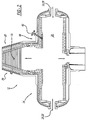
- FIG. 2 an enlarged view of two-stage gasifier 12 is depicted with sheathed or protected thermal sensing device 62 located completely through layers of refractory brick that define first stage gasifier area 24.
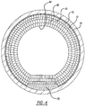
- Figure 4 depicts an enlarged view of layers of refractory brick that define first stage gasifier area 24.
- layers of refractory brick may include, from an inside diameter or wall to an outside diameter or wall of first stage gasifier area 24 of two-stage gasifier 12: a first hot face brick layer 64, a second hot face brick layer 66, a safety liner brick layer 68, an insulating firebrick layer 70 (also known as an I.F.B.
- a castable grating layer 76 may also form a section of an exterior or outside wall that defines first stage gasifier area 24.
- sensing device 62 may pass through all layers defining first stage gasifier area 24.
- sensing device 62 may utilize a temperature measuring device such as a sapphire thermal sensor 78, which may be encased or surrounded by an alumina tube 80.
- a thermocouple may reside within sapphire thermal sensor 78, which may protect the thermocouple.
- Sapphire thermal sensor 78 resists hydrogen permeation and since hydrogen gas from within first stage gasifier volume 25 may seep through refractory brick surrounding sapphire thermal sensor 78, wires of thermocouple are sufficiently protected from any hydrogen gas and slag corrosion.
- the term "thermocouple” is a temperature sensing device that may include the thermocouple sensor and wires and any support, insulation, protection, or mounting means used incident with the thermocouple sensors and wires.
- Alumina tube 80 may then be contact-wrapped in ceramic fiber paper 82.
- a steel tube 84 may be placed over sapphire thermal sensor 78 and ceramic fiber paper 82 for at least a portion of the overall length of sensing device 62.
- Steel tube 84 may mount to a first flange 86, which may be mounted to a second flange 88.
- Abutting and mounted to first flange 86 is a metal sleeve 90, which may be cylindrical in shape and completely surround sapphire thermal sensor 78, except at a protective tip end 91 of metal sleeve 90.
- Protective tip end 91 may be open and unobstructed to permit air to flow freely to sapphire thermal sensor tip 79 to permit accurate temperature readings using sensing device 62.
- ceramic fiber paper 94 may be installed, such as by stuffing with a tool and/or by hand packing. Such stuffing with a tool and/or by hand packing ceramic fiber paper 94 may be completed before mounting (e.g. welding) metal sleeve 90 to second flange 88.
- a thermal management material may be installed around alumina tube 80 such as between alumina tube 80 and metal sleeve 90 in volume of space 98a.
- Thermal management material may be SAFFIL brand fibre, which may resist heat or act as a thermal barrier and provide structural support to prevent movement of alumina tube and sapphire thermal sensor 78 within metal sleeve 90. Thermal management material may act as a centering device for sapphire thermal sensor 78 within metal sleeve 90. Metal sleeve 90 is a protective sheath for sapphire thermal sensor 78.
- Other examples of thermal sensors applicable to the present disclosure may include ultrasonic thermal sensors, thermocouples, optical thermometry, and acoustic or sound thermometry.
- the temperature response that is, the time for a change in gasifier temperature to be reflected in a thermocouple response depends in part on the thickness of the brick layer between the thermocouple and the gasification zone or volume of the first stage gasifier volume 25.
- the minor insulating effect of the hot face brick will result in the thermocouple mounted behind the hot face brick to potentially read lower than the actual gas temperature.
- the time delay and temperature differential are more pronounced with thicker layers of hot face brick between the temperature or thermocouple sensor and the first stage gasifier volume 25.
- the thickness of the layer of hot face brick between the thermocouple sensor and first stage gasifier volume 25 therefore should be less than about 31 cm (12 inches), preferably less than 23 cm (9 inches), more preferably less than about 15 cm (6 inches), and most preferably less than about 12 cm (4.5 inches).
- the hot face brick is subjected to molten slag and the atmosphere of first stage gasifier volume, and the hot face brick may wear. Wear may be accelerated by stresses caused by the reduced thickness of the hot face brick in front of the thermocouple. Therefore, the thickness of the hot face brick is preferably greater than about 5 cm (2 inches), more preferably greater than about 8.9 cm (3.5 inches).
- the thickness of the hot face brick is preferably greater than about 8.9 cm (3.5 inch), more preferably greater than about 10 cm (4 inches).
- FIG. 5 an enlarged view of a refractory brick wall section 99 through which sensing device 62 passes is depicted.
- Refractory brick wall section 99 may be characteristic of that explained in conjunction with Figure 4 .
- Sensing device 62 passes through first hot face brick layer 64, second hot face brick layer 66, safety liner brick layer 68, insulating fire brick layer 70, ceramic fiber paper layer 72, hexagon grating 74, and exterior brick layer 75, which may he an outermost layer of two-stage gasifier 12.
- Protective tip end 91 of sensing device 62 may or may not protrude past an interior surface 104 that defines a boundary of first stage gasifier area 24.
- protective tip end 91 of sensing device 62 protrudes past an interior surface 104 that defines a boundary of first stage gasifier area 24
- protective tip end 91 resides within a protruding refractory brick 100.
- Protective tip end 91 may reside completely within protruding refractory brick 100 such that any further penetration or insertion of sensing device 62 into hole 102, which may be bored or cast, within protruding refractory brick 100 would cause protective tip end 91 to strike an interior surface that defines an end wall adjacent a longitudinal end of metal sleeve 90, as if tip end were to continue to extend and make metal sleeve 90 longer.
- Hole 102 may be cylindrical. Hole 102 may also be known as a blind hole because it is not a through hole or through-and-through hole.
- Protruding refractory brick 100 may be considered or referred to as "protruding” because it protrudes or encroaches beyond the generally consistent surface or face 110 of first hot face brick layer 64, as depicted in Figure 5 , that faces toward the inside or volume known as first stage gasifier area 24 of two-stage gasifier 12.
- protruding refractory brick 100 and its housing of protective tip end 91 of sensing device 62 are herein presented.
- protruding refractory brick 100 which may be a refractory brick with hole 102 (e.g. a blind hole) for sensing device 62, may be resident as a refractory brick that forms part of the boundary of interior first stage gasifier area 24.
- Protruding refractory brick 100 as depicted in Figure 5 , may also be known as a protruding refractory brick, and protrude into interior first stage gasifier area 24 and into a combined or mixed stream of oxygen 20 and slurry 26. Combined or mixed stream of oxygen 20 and slurry 26 may contact a face 106 of protruding refractory brick 100.
- Face 106 of protruding refractory brick 100 may be flat and may form an obtuse angle with an abutting or adjacent face 110 of an inside surface forming a boundary of first stage gasifier area 24. Face 106 of protruding refractory brick 100 may form an angle with an abutting or adjacent face 110 of an inside surface forming a boundary of first stage gasifier area 24 that is greater than 90 degrees.
- Upon combined or mixed stream of oxygen 20 and slurry 26 striking flat face 106, such combined or mixed stream 20, 26 is directed along flat face 106 and then away from protruding refractory brick 100 and toward a central or center area of first stage gasifier area 24.
- Figures 6-8 are side views of protruding refractory brick 100 depicting further details of protruding refractory brick 100.
- Figure 6 depicts hole 102 that is not a through hole, but rather bottoms out and has brick material 114 surrounding the cylindrical portion of hole 102.
- Hole 102 may be a blind hole, which is not a through hole.
- Brick material also forms an end wall 11 6 which defines bottomed-out portion or end wall 11 8 that defines hole 102.
- Figure 6 also depicts flat face 106 which is also formed in protruding refractory brick 100 such that it forms an obtuse angle 108 ( Figure 5 ) with brick face 110 of an adjacent or abutting refractory brick when installed in first stage gasifier area 24.
- Figure 7 depicts brick face 120 and brick face 122 which correspond to flat faces that are on opposite sides of protruding refractory brick 100.
- Flat faces 120, 122 are non-parallel and oriented such that their faces would intersect if extended in an infinite plane.
- an edge of face 120 and an edge of face 122 forms boundary ends of a curved or convex face 128 that is a face into which hole 102 is made.
- a flat face 130 On a side of protruding refractory brick 100 that is opposite curved face 128, a flat face 130 resides and has no bored hole through it because hole 102 is a blind hole.
- a temperature measurement system for a two-stage gasifier 12 may employ a refractory wall, which may be layers of refractory bricks to form a refractory brick wall section 99, and a sensing device 62 (e.g. thermal sensor) with an end 91 having a temperature sensing tip 79 that resides completely or partially within refractory brick wall section 99.
- a temperature measurement system may employ a protruding refractory brick 100 as part of refractory brick wall section 99, wherein protruding refractory brick 100 surrounds end 91 of temperature sensing tip 79.
- Protruding refractory brick 100 resides in a fluid stream of first stage gasifier area 24.
- Protruding refractory brick 100 may have multiple faces and protruding refractory brick first face 106 may face into or toward mixed fluid stream 20, 26 within first stage gasifier area 24. Protruding refractory brick first face 106 may generally face upstream relative to the flow direction of mixed fluid stream 20, 26. In another example, protruding refractory brick first face 106, which may be flat, generally is situated at an angle that is not 90 degrees relative to a general flow path of fluid stream 20, 26.
- Protruding refractory brick 100 may have a second face 118, which may be flat, that contacts a second refractory brick 109, which forms a boundary of a first stage gasifier area 24 and comes in contact with gaseous flow path of fluid stream 20, 26 within first stage gasifier area 24.
- Protruding refractory brick 100 may have a third face 130 that is generally parallel to the mixed fluid stream 20, 26 through first stage gasifier area 24.
- Protruding refractory brick first face 106 may share an edge due to intersection with protruding refractory brick third face 130.
- Protruding refractory brick first face 106 may have an edge that contacts an edge with adjacent, second refractory brick 109.
- Protruding refractory brick first face 106 has a first edge that contacts the second refractory brick 109, and the protruding refractory brick first face 106 shares a second edge with the protruding refractory brick third face 130.
- a temperature measurement system for a gasifier may employ first stage gasifier area 24 having first stage refractory brick wall 98 that defines first stage gasifier volume 25, second stage gasifier area 28 having second stage refractory wall 29 that defines a second stage gasifier volume.
- Protruding refractory brick 100 protrudes from interior surface 104 of first stage refractory brick wall 98 and toward first stage gasifier volume 25.
- Temperature sensing device 62 having temperature sensing tip 79 and protective tip end 91 may reside within protruding refractory brick 100.
- First stage gasifier area 24 may employ a plurality of brick layers 64, 66, 68, 70, 75 that together form first stage refractory wall 98.
- Temperature sensor 62 resides completely through the plurality of brick layers, except the protruding refractory brick 100.
- Protruding refractory brick 100 protrudes from the plurality of brick layers, and specifically interior surface 104 defining first stage gasifier volume 25, and into the first stage gasifier volume 25.
- Protruding refractory brick first face 106 may form an angle that is not 90 degrees relative to a general flow path of the mixed fluid stream 20, 26 through first stage gasifier volume 25.
- Protruding refractory brick first face 106 may form an angle of 45 degrees or approximately 45 degrees relative to a general flow path of the fluid stream through the first stage gasifier volume.
- Protruding refractory brick first face 106 may form an angle of approximately 45 degrees relative to a general flow path of mixed fluid stream 20, 26 through first stage gasifier volume 25. Protruding refractory brick first face 106 may face against a general flow path of the fluid stream through the first stage gasifier volume. End 91 of temperature sensing tip 79 resides in a portion of the protruding refractory brick 100 that protrudes into the general flow path of mixed fluid stream 20, 26 through first stage gasifier volume 25. Protruding refractory brick 100 defines a blind hole 102 within which the temperature sensing tip 79 of sapphire thermal sensor 78 resides. Temperature sensing tip 79 may reside in a portion of protruding refractory brick 100 that protrudes into a general flow path of mixed fluid stream 20,26 that flows through first stage gasifier volume 25.
- temperature sensing tip 79 of sapphire thermal sensor 78 is protected from direct contact with mixed fluid stream 20, 26 through first stage gasifier 24. Not only is temperature sensing tip 79 protected from mixed fluid stream 20, 26 and residual buildup of heated debris from mixed fluid stream 20, 26, because protruding refractory brick 100 provides a sheath or protective area and becomes the same temperature as mixed fluid stream 20, 26, accurate temperatures may be obtained for mixed fluid stream 20, 26 and the life of sapphire thermal sensor 78 may be extended since mixed fluid stream 20, 26 is not directed directly into temperature sensing tip 79.
- metal sleeve 90 also protects the full length of sapphire thermal sensor 78, including temperature sending tip 79 of sapphire thermal sensor 78. Temperature sensing tip 79 is protected by protective tip end 91 of metal sleeve 90.
Landscapes
- Chemical & Material Sciences (AREA)
- Engineering & Computer Science (AREA)
- Combustion & Propulsion (AREA)
- Oil, Petroleum & Natural Gas (AREA)
- Organic Chemistry (AREA)
- Physics & Mathematics (AREA)
- General Physics & Mathematics (AREA)
- Chemical Kinetics & Catalysis (AREA)
- General Chemical & Material Sciences (AREA)
- Spectroscopy & Molecular Physics (AREA)
- Acoustics & Sound (AREA)
- Waste-Gas Treatment And Other Accessory Devices For Furnaces (AREA)
- Measuring Temperature Or Quantity Of Heat (AREA)
- Life Sciences & Earth Sciences (AREA)
- Health & Medical Sciences (AREA)
- Incineration Of Waste (AREA)
- Investigating Or Analyzing Materials Using Thermal Means (AREA)
- Food Science & Technology (AREA)
- Medicinal Chemistry (AREA)
- Analytical Chemistry (AREA)
- Biochemistry (AREA)
- General Health & Medical Sciences (AREA)
- Immunology (AREA)
- Pathology (AREA)
Description
- This disclosure relates to physical protection of a thermal sensor subjected to high temperatures and corrosive environments.
- In a slagging gasifier within a syngas production facility, a thermal sensor may be used to measure temperatures in a first stage location within the slagging gasifier to control temperature adjustments. By controlling temperature within the slagging gasifier, solid feed syngas conversion may be optimized which may reduce refractory wear rates and maintenance costs associated with the slagging gasifier. While current thermal sensors have proven useful for temperature measurement within a slagging gasifier, their use is not with limitations. What is needed then is a device that accurately measures temperatures, does not accumulate slag, resists physical contact with its surroundings, and that has an extended useful life over current temperature measuring devices.
-
WO00/19177 JP201262376 JP2004301615 US3610045 andWO03/081192 - According to one aspect thereof, the present disclosure relates to a two-stage gasifier comprising a temperature measurement system according to claim 1.
- Embodiments of the temperature measurement system are defined in the dependent claims.
- A more complete understanding of the present invention and benefits thereof may he acquired by referring to the follow description taken in conjunction with the accompanying drawings in which:
-
Figure 1 is a diagram of a syngas production facility within which the teachings of the present disclosure may be employed; -
Figure 2 is an enlarged view of a gasifier indicating the location of a thermal sensor structure in accordance with the teachings of the present disclosure; -
Figure 3 is a side view of a thermal measuring device in accordance with the teachings of the present disclosure; -
Figure 4 is a cross-sectional view of a gasifier wall depicting a location of a thermal measuring device in accordance with the teachings of the present disclosure; -
Figure 5 is an enlarged side view of a gasifier wall depicting a thermal measuring device located within the gasifier wall in accordance with the teachings of the present disclosure; -
Figure 6 is a side view of a refractory brick of a gasifier wall in accordance with the teachings of the present disclosure; -
Figure 7 is a side view of a refractory brick of a gasifier wall in accordance with the teachings of the present disclosure; and -
Figure 8 is a side view of a refractory brick of a gasifier wall in accordance with the teachings of the present disclosure. - Turning now to
Figures 1-8 , and beginning withFigure 1 , inventive features and concepts will be presented; however, the invention is not limited to embodiments described or depicted inFigures 1-8 .Figure 1 depicts asyngas production facility 10 with a two-stage gasifier 12. In feed preparation for two-stage gasifier 12, low-cost feedstocks, such as bituminous and sub-bituminous coal, or petroleum coke, are crushed and mixed with water in a crusher-mixer 14 to form a pumpable slurry. The slurry is pumped via apump 16 from aslurry tank 18 and into two-stage gasifier 12 along withoxygen 20 from anoxygen plant 22. Gasification occurs in two-stage gasifier 12 whereslurry 26 andoxygen 20 react readily with oxygen in the firststage gasifier area 24 within two-stage gasifier 12 to form hydrogen, carbon monoxide, carbon dioxide and methane. During gasification, firststage gasifier area 24 within two-stage gasifier 12 is elevated to a high temperature (e.g. 1427°C-1482°C (2,600-2,700 degrees F)) to ensure complete conversion of all feedstock material. Synthesis gas from the horizontal, firststage gasifier area 24 eventually enters a vertical, secondstage gasifier area 28. Before entering secondstage gasifier area 28,additional slurry 26 is added to the gas passing between firststage gasifier area 24 and secondstage gasifier area 28, such as atthroat passage 30 of two-stage gasifier 12. Processes performed within secondstage gasifier area 28 increase efficiency and reduce oxygen consumption. Inorganic materials from the coal are trapped in a glassy matrix resembling coarse sand. This sand-like material is referred to as slag, is inert and has a variety of uses, such as in the construction industry. Typically, no ash waste results from the gasification process. - Syngas
production facility 10 utilizes a unique firetube syngas cooler to recover heat and produce high-pressure steam insteam generator 32. Steam produced insteam generator 32 is routed insteam pipes electrical generator 38 to generate electrical power in addition to the electrical power from a gas turbine andelectrical generator 40. Syngasproduction facility 10 may incorporatecandle filter elements 42 to remove all particulates from the syngas flowing intocandle filter elements 42. This simple, dry system is significantly more efficient than wet scrubbing systems and removes more particulates. Syngas flowing throughcandle filter elements 42 results in recycled char that may be directed into firststage gasifier area 24 of two-stage gasifier 12 viachar pipe 44. - As sour synthesis gas is cooled, steam is injected into the gas stream. A catalytic reaction follows which enhances the hydrogen content of the syngas. The size of this "shift" equipment is minimized in the process as a result of conversion process reactions that previously occurred in the second
stage gasifier area 28 of the two-stage gasifier 12. Sour water may flow fromtank 48 through sourwater feed pipe 46 and into crusher-mixer 14. In a series of chemical process steps, chlorides, mercury and sulfur contaminants are removed from thesyngas stream 50 after flowing fromtank 48 and into vessels ofcontaminant removal area 52. Mercury 54 is captured in a carbon bed for disposal in approved sites whilesulfur 56 in the synthesis gas is recovered and converted to elemental sulfur, which may be sold in agricultural and other markets. The process ofsyngas production facility 10 recycles unconverted tailgas to provide excellent success regarding sulfur recovery. Carbon dioxide (CO2) capture is economically achieved at a fraction of the cost compared to conventional boiler combustion technology because carbon dioxide in a CO2 stream 60 is separated from the synthesis gas, dried and compressed for use in consumer products, or injected underground for enhanced oil recovery, as example uses. Clean, hydrogen rich synthesis gas in ahydrogen stream 58 may be utilized in a gas turbine andelectrical generator 40 to generate electric power, and heat recovered from theclean exhaust 61 stream of the gas turbine andelectrical generator 40 may be used to generate additional steam for steam turbine andelectrical generator 38. To improve enhanced first stage gasifier temperature measurement and control, which ensures optimized solid feed syngas conversion and reduce gasifier refractory wear rates and maintenance costs, asensing device 62 may be situated through a wall of two-stage gasifier 12. - Turning now to
Figure 2 , an enlarged view of two-stage gasifier 12 is depicted with sheathed or protectedthermal sensing device 62 located completely through layers of refractory brick that define firststage gasifier area 24.Figure 4 depicts an enlarged view of layers of refractory brick that define firststage gasifier area 24. Continuing withFigure 4 , layers of refractory brick may include, from an inside diameter or wall to an outside diameter or wall of firststage gasifier area 24 of two-stage gasifier 12: a first hotface brick layer 64, a second hotface brick layer 66, a safetyliner brick layer 68, an insulating firebrick layer 70 (also known as an I.F.B. layer), a ceramicfiber paper layer 72, and ahexagon grating layer 74. Acastable grating layer 76 may also form a section of an exterior or outside wall that defines firststage gasifier area 24. Although not depicted inFigure 4 , but depicted inFigure 2 ,sensing device 62 may pass through all layers defining firststage gasifier area 24. - Turning to
Figure 3 ,sensing device 62 may utilize a temperature measuring device such as a sapphirethermal sensor 78, which may be encased or surrounded by analumina tube 80. A thermocouple may reside within sapphirethermal sensor 78, which may protect the thermocouple. Sapphirethermal sensor 78 resists hydrogen permeation and since hydrogen gas from within firststage gasifier volume 25 may seep through refractory brick surrounding sapphirethermal sensor 78, wires of thermocouple are sufficiently protected from any hydrogen gas and slag corrosion. As used herein, the term "thermocouple" is a temperature sensing device that may include the thermocouple sensor and wires and any support, insulation, protection, or mounting means used incident with the thermocouple sensors and wires.Alumina tube 80 may then be contact-wrapped inceramic fiber paper 82. Asteel tube 84 may be placed over sapphirethermal sensor 78 andceramic fiber paper 82 for at least a portion of the overall length ofsensing device 62.Steel tube 84 may mount to afirst flange 86, which may be mounted to asecond flange 88. Abutting and mounted tofirst flange 86 is ametal sleeve 90, which may be cylindrical in shape and completely surround sapphirethermal sensor 78, except at aprotective tip end 91 ofmetal sleeve 90.Protective tip end 91 may be open and unobstructed to permit air to flow freely to sapphirethermal sensor tip 79 to permit accurate temperature readings usingsensing device 62. In a volume ofspace 96 surroundingsteel tube 84, which more specifically may be betweensteel tube 84 andmetal sleeve 90,ceramic fiber paper 94 may be installed, such as by stuffing with a tool and/or by hand packing. Such stuffing with a tool and/or by hand packingceramic fiber paper 94 may be completed before mounting (e.g. welding)metal sleeve 90 tosecond flange 88. After mounting ofmetal sleeve 90 tofirst flange 86 andsecond flange 88 is complete, a thermal management material may be installed aroundalumina tube 80 such as betweenalumina tube 80 andmetal sleeve 90 in volume of space 98a. Thermal management material may be SAFFIL brand fibre, which may resist heat or act as a thermal barrier and provide structural support to prevent movement of alumina tube and sapphirethermal sensor 78 withinmetal sleeve 90. Thermal management material may act as a centering device for sapphirethermal sensor 78 withinmetal sleeve 90.Metal sleeve 90 is a protective sheath for sapphirethermal sensor 78. Other examples of thermal sensors applicable to the present disclosure may include ultrasonic thermal sensors, thermocouples, optical thermometry, and acoustic or sound thermometry. - The temperature response, that is, the time for a change in gasifier temperature to be reflected in a thermocouple response depends in part on the thickness of the brick layer between the thermocouple and the gasification zone or volume of the first
stage gasifier volume 25. In addition, the minor insulating effect of the hot face brick will result in the thermocouple mounted behind the hot face brick to potentially read lower than the actual gas temperature. The time delay and temperature differential are more pronounced with thicker layers of hot face brick between the temperature or thermocouple sensor and the firststage gasifier volume 25. The thickness of the layer of hot face brick between the thermocouple sensor and firststage gasifier volume 25 therefore should be less than about 31 cm (12 inches), preferably less than 23 cm (9 inches), more preferably less than about 15 cm (6 inches), and most preferably less than about 12 cm (4.5 inches). At the same time, the hot face brick is subjected to molten slag and the atmosphere of first stage gasifier volume, and the hot face brick may wear. Wear may be accelerated by stresses caused by the reduced thickness of the hot face brick in front of the thermocouple. Therefore, the thickness of the hot face brick is preferably greater than about 5 cm (2 inches), more preferably greater than about 8.9 cm (3.5 inches). For hydrocarbonaceous feedstock that produces higher quantities of molten slag, i.e., greater than about 0.1 percent by weight slag, the thickness of the hot face brick is preferably greater than about 8.9 cm (3.5 inch), more preferably greater than about 10 cm (4 inches). By using sapphirethermal sensor 78, which may be encased or surrounded by analumina tube 80, temperature response times may be lessened or eliminated. - Turning to
Figure 5 , an enlarged view of a refractorybrick wall section 99 through whichsensing device 62 passes is depicted. Refractorybrick wall section 99 may be characteristic of that explained in conjunction withFigure 4 .Sensing device 62 passes through first hotface brick layer 64, second hotface brick layer 66, safetyliner brick layer 68, insulatingfire brick layer 70, ceramicfiber paper layer 72, hexagon grating 74, andexterior brick layer 75, which may he an outermost layer of two-stage gasifier 12.Protective tip end 91 ofsensing device 62 may or may not protrude past aninterior surface 104 that defines a boundary of firststage gasifier area 24. Regardless of whetherprotective tip end 91 ofsensing device 62 protrudes past aninterior surface 104 that defines a boundary of firststage gasifier area 24,protective tip end 91 resides within a protrudingrefractory brick 100.Protective tip end 91 may reside completely within protrudingrefractory brick 100 such that any further penetration or insertion ofsensing device 62 intohole 102, which may be bored or cast, within protrudingrefractory brick 100 would causeprotective tip end 91 to strike an interior surface that defines an end wall adjacent a longitudinal end ofmetal sleeve 90, as if tip end were to continue to extend and makemetal sleeve 90 longer. Stated slightly differently, whenprotective tip end 91 ofsensing device 62 is inserted intohole 102, sapphirethermal sensor 78 and its surroundingalumina tube 80, are completely surrounded by walls ofhole 102.Hole 102 may be cylindrical.Hole 102 may also be known as a blind hole because it is not a through hole or through-and-through hole. - Protruding
refractory brick 100 may be considered or referred to as "protruding" because it protrudes or encroaches beyond the generally consistent surface or face 110 of first hotface brick layer 64, as depicted inFigure 5 , that faces toward the inside or volume known as firststage gasifier area 24 of two-stage gasifier 12. Advantages of protrudingrefractory brick 100 and its housing ofprotective tip end 91 ofsensing device 62 are herein presented. - With continued reference to
Figure 5 , protrudingrefractory brick 100, which may be a refractory brick with hole 102 (e.g. a blind hole) forsensing device 62, may be resident as a refractory brick that forms part of the boundary of interior firststage gasifier area 24. Protrudingrefractory brick 100, as depicted inFigure 5 , may also be known as a protruding refractory brick, and protrude into interior firststage gasifier area 24 and into a combined or mixed stream ofoxygen 20 andslurry 26. Combined or mixed stream ofoxygen 20 andslurry 26 may contact aface 106 of protrudingrefractory brick 100. Face 106 of protrudingrefractory brick 100 may be flat and may form an obtuse angle with an abutting oradjacent face 110 of an inside surface forming a boundary of firststage gasifier area 24. Face 106 of protrudingrefractory brick 100 may form an angle with an abutting oradjacent face 110 of an inside surface forming a boundary of firststage gasifier area 24 that is greater than 90 degrees. Upon combined or mixed stream ofoxygen 20 andslurry 26 strikingflat face 106, such combined ormixed stream flat face 106 and then away from protrudingrefractory brick 100 and toward a central or center area of firststage gasifier area 24. With combined ormixed stream refractory brick 100 refractory brick is certain to warm to temperatures consistent or equal to that of combined ormixed stream mixed stream refractory brick 100,air space 112 within whichprotective tip end 91 resides, also warms to the temperature of combined ormixed stream protective tip end 91 within which sapphirethermal sensor 78 resides is warmed, sapphirethermal sensor 78 accurately senses the temperature ofair space 112 and thus, a temperature of combined ormixed stream -
Figures 6-8 are side views of protrudingrefractory brick 100 depicting further details of protrudingrefractory brick 100.Figure 6 depictshole 102 that is not a through hole, but rather bottoms out and hasbrick material 114 surrounding the cylindrical portion ofhole 102.Hole 102 may be a blind hole, which is not a through hole. Brick material also forms an end wall 11 6 which defines bottomed-out portion or end wall 11 8 that defineshole 102.Figure 6 also depictsflat face 106 which is also formed in protrudingrefractory brick 100 such that it forms an obtuse angle 108 (Figure 5 ) withbrick face 110 of an adjacent or abutting refractory brick when installed in firststage gasifier area 24.Figure 7 depictsbrick face 120 andbrick face 122 which correspond to flat faces that are on opposite sides of protrudingrefractory brick 100. Flat faces 120, 122 are non-parallel and oriented such that their faces would intersect if extended in an infinite plane. Moreover, an edge offace 120 and an edge offace 122 forms boundary ends of a curved orconvex face 128 that is a face into whichhole 102 is made. On a side of protrudingrefractory brick 100 that is oppositecurved face 128, aflat face 130 resides and has no bored hole through it becausehole 102 is a blind hole. - Stating teachings of the present disclosure slightly differently, a temperature measurement system for a two-
stage gasifier 12 may employ a refractory wall, which may be layers of refractory bricks to form a refractorybrick wall section 99, and a sensing device 62 (e.g. thermal sensor) with anend 91 having atemperature sensing tip 79 that resides completely or partially within refractorybrick wall section 99. A temperature measurement system may employ a protrudingrefractory brick 100 as part of refractorybrick wall section 99, wherein protrudingrefractory brick 100 surroundsend 91 oftemperature sensing tip 79. Protrudingrefractory brick 100 resides in a fluid stream of firststage gasifier area 24. Protrudingrefractory brick 100 may have multiple faces and protruding refractory brickfirst face 106 may face into or towardmixed fluid stream stage gasifier area 24. Protruding refractory brickfirst face 106 may generally face upstream relative to the flow direction of mixedfluid stream first face 106, which may be flat, generally is situated at an angle that is not 90 degrees relative to a general flow path offluid stream refractory brick 100 may have asecond face 118, which may be flat, that contacts a secondrefractory brick 109, which forms a boundary of a firststage gasifier area 24 and comes in contact with gaseous flow path offluid stream stage gasifier area 24. Protrudingrefractory brick 100 may have athird face 130 that is generally parallel to themixed fluid stream stage gasifier area 24. Protruding refractory brickfirst face 106 may share an edge due to intersection with protruding refractory brickthird face 130. Protruding refractory brickfirst face 106 may have an edge that contacts an edge with adjacent, secondrefractory brick 109. Protruding refractory brickfirst face 106 has a first edge that contacts the secondrefractory brick 109, and the protruding refractory brickfirst face 106 shares a second edge with the protruding refractory brickthird face 130. - In another example, a temperature measurement system for a gasifier may employ first
stage gasifier area 24 having first stagerefractory brick wall 98 that defines firststage gasifier volume 25, secondstage gasifier area 28 having second stagerefractory wall 29 that defines a second stage gasifier volume. Protrudingrefractory brick 100 protrudes frominterior surface 104 of first stagerefractory brick wall 98 and toward firststage gasifier volume 25.Temperature sensing device 62 havingtemperature sensing tip 79 andprotective tip end 91 may reside within protrudingrefractory brick 100. Firststage gasifier area 24 may employ a plurality of brick layers 64, 66, 68, 70, 75 that together form first stagerefractory wall 98.Temperature sensor 62 resides completely through the plurality of brick layers, except the protrudingrefractory brick 100. Protrudingrefractory brick 100 protrudes from the plurality of brick layers, and specificallyinterior surface 104 defining firststage gasifier volume 25, and into the firststage gasifier volume 25. Protruding refractory brickfirst face 106 may form an angle that is not 90 degrees relative to a general flow path of themixed fluid stream stage gasifier volume 25. Protruding refractory brickfirst face 106 may form an angle of 45 degrees or approximately 45 degrees relative to a general flow path of the fluid stream through the first stage gasifier volume. Protruding refractory brickfirst face 106 may form an angle of approximately 45 degrees relative to a general flow path of mixedfluid stream stage gasifier volume 25. Protruding refractory brickfirst face 106 may face against a general flow path of the fluid stream through the first stage gasifier volume.End 91 oftemperature sensing tip 79 resides in a portion of the protrudingrefractory brick 100 that protrudes into the general flow path of mixedfluid stream stage gasifier volume 25. Protrudingrefractory brick 100 defines ablind hole 102 within which thetemperature sensing tip 79 of sapphirethermal sensor 78 resides.Temperature sensing tip 79 may reside in a portion of protrudingrefractory brick 100 that protrudes into a general flow path of mixedfluid stream stage gasifier volume 25. - There are many advantages to teachings of the present disclosure. One advantage is that
temperature sensing tip 79 of sapphirethermal sensor 78, or whatever thermal sensor is used, is protected from direct contact with mixedfluid stream first stage gasifier 24. Not only istemperature sensing tip 79 protected frommixed fluid stream mixed fluid stream refractory brick 100 provides a sheath or protective area and becomes the same temperature asmixed fluid stream fluid stream thermal sensor 78 may be extended sincemixed fluid stream temperature sensing tip 79. Moreover,metal sleeve 90 also protects the full length of sapphirethermal sensor 78, includingtemperature sending tip 79 of sapphirethermal sensor 78.Temperature sensing tip 79 is protected byprotective tip end 91 ofmetal sleeve 90. - In closing, it should be noted that the discussion of any reference is not an admission that it is prior art to the present invention, especially any reference that may have a publication date after the priority date of this application. At the same time, each and every claim below is hereby incorporated into this detailed description or specification as an additional embodiment of the present invention.
Claims (17)
- A two-stage gasifier (12) comprising a temperature measurement system including:a refractory wall (99) comprising a plurality of refractory brick layers defining a first stage gasifier volume;a protruding refractory brick (100) as part of the refractory wall (99); anda thermal sensor (62) with a temperature sensing tip end (79) that resides completely within the plurality of refractory brick layers of the refractory wall (99),wherein the protruding refractory brick (100) surrounds the temperature sensing tip end (79).
- The two-stage gasifier (12) according to claim 1, wherein the protruding refractory brick (100) completely surrounds the tip end (91) of the thermal sensor (62) and resides in a fluid stream (20, 26) of the gasifier (12).
- The two-stage gasifier (12) according to claim 2, further comprising:
a protruding refractory brick first face (106) that faces into the fluid stream (20, 26) of the gasifier (12). - The two-stage gasifier (12) according to claim 3, wherein the protruding refractory brick first face (106) faces upstream relative to the fluid stream (20, 26).
- The two-stage gasifier (12) according to claim 4, wherein the protruding refractory brick first face (106) faces an angle that is not 90 degrees relative to a general flow path of the fluid stream (20, 26).
- The two-stage gasifier (12) according to claim 5, wherein the protruding refractory brick (100) further comprises:
a protruding refractory brick second face (118) that contacts a second refractory brick (109) that forms a boundary of a first stage gasifier area (24). - The two-stage gasifier (12) according to claim 6, further comprising:
a protruding refractory brick third face (130) that is parallel to the fluid stream (20, 26) of the gasifier (12). - The two-stage gasifier (12) according to claim 7, wherein the protruding refractory brick first face (106) has a first edge that contacts the second refractory brick (109), and the protruding refractory brick first face (106) shares a second edge with the protruding refractory brick third face (130).
- The two-stage gasifier (12) according to claim 1, comprising:a first stage gasifier (24) having a first stage refractory wall (98) that defines a first stage gasifier volume (25); anda second stage gasifier (28) having a second stage refractory wall (29) that defines a second stage gasifier volume (30);
whereinthe protruding refractory brick (100) protrudes from the first stage refractory wall (98) and toward the first stage gasifier volume (25); andthe temperature sensing tip (79) resides within the protruding refractory brick (100). - The two-stage gasifier (12) according to claim 9, further comprising:
a plurality of brick layers (64, 66, 68, 70, 75) that together form the first stage refractory wall (98), wherein the thermal sensor (62) resides completely through the plurality of brick layers (64, 66, 68, 70, 75), except the protruding refractory brick (100). - The two-stage gasifier (12) according to claim 10, wherein the protruding refractory brick (100) protrudes from the plurality of brick layers (64, 66, 68, 70, 75) and into the first stage gasifier volume (25).
- The two-stage gasifier (12) according to claim 11, the protruding refractory brick (100) further comprising:
a protruding refractory brick first face (106) that forms an angle that is not 90 degrees relative to a general flow path of the fluid stream (20, 26) through the first stage gasifier volume (25). - The two-stage gasifier (12) according to claim 11, wherein the protruding refractory brick first face (106) forms an angle of approximately 45 degrees relative to a general flow path of the fluid stream (20, 26) through the first stage gasifier volume (25).
- The two-stage gasifier (12) according to claim 13, wherein the temperature sensing tip (79) resides in a portion of the protruding refractory brick (100) that protrudes into the general flow path of the fluid stream (20, 26) through the first stage gasifier volume (25).
- The two-stage gasifier (12) according to claim 14, wherein the protruding refractory brick (100) defines a blind hole (102) within which the temperature sensing tip (79) of the thermal sensor (62) resides.
- The two-stage gasifier (12) according to claim 9, wherein:
the protruding refractory brick (100) defines a blind hole (102) within which the temperature sensing tip (79) of the thermal sensor (62) resides. - The two-stage gasifier (12) according to claim 16, further comprising:
a protective metal sleeve (90) surrounding the thermal sensor (62), wherein the temperature sensing tip (79) of the thermal sensor (62) resides in a portion of the protruding refractory brick (100) that protrudes into a general flow path of the fluid stream (20, 26) through the first stage gasifier volume (25).
Priority Applications (1)
| Application Number | Priority Date | Filing Date | Title |
|---|---|---|---|
| PL13857821T PL2926100T3 (en) | 2012-11-30 | 2013-11-11 | Thermal sensing system |
Applications Claiming Priority (2)
| Application Number | Priority Date | Filing Date | Title |
|---|---|---|---|
| US201261731927P | 2012-11-30 | 2012-11-30 | |
| PCT/US2013/069465 WO2014085071A1 (en) | 2012-11-30 | 2013-11-11 | Thermal sensing system |
Publications (3)
| Publication Number | Publication Date |
|---|---|
| EP2926100A1 EP2926100A1 (en) | 2015-10-07 |
| EP2926100A4 EP2926100A4 (en) | 2016-07-06 |
| EP2926100B1 true EP2926100B1 (en) | 2020-07-29 |
Family
ID=50825640
Family Applications (1)
| Application Number | Title | Priority Date | Filing Date |
|---|---|---|---|
| EP13857821.6A Active EP2926100B1 (en) | 2012-11-30 | 2013-11-11 | Thermal sensing system |
Country Status (11)
| Country | Link |
|---|---|
| US (1) | US9766133B2 (en) |
| EP (1) | EP2926100B1 (en) |
| JP (2) | JP6247699B2 (en) |
| KR (2) | KR101977336B1 (en) |
| CN (1) | CN103852178B (en) |
| AU (1) | AU2013353340B2 (en) |
| CA (1) | CA2893331C (en) |
| ES (1) | ES2827220T3 (en) |
| PL (1) | PL2926100T3 (en) |
| PT (1) | PT2926100T (en) |
| WO (1) | WO2014085071A1 (en) |
Families Citing this family (9)
| Publication number | Priority date | Publication date | Assignee | Title |
|---|---|---|---|---|
| EP1156253B1 (en) | 1999-10-29 | 2005-12-28 | Piolax Inc. | Corrugated resin tube |
| US8211191B2 (en) * | 2007-08-07 | 2012-07-03 | Phillips 66 Company | Upright gasifier |
| WO2017066881A1 (en) | 2015-10-23 | 2017-04-27 | Atomic Energy Of Canada Limited / Énergie Atomique Du Canada Limitée | Test apparatus and instrumented conduit for use with same |
| CN105784187B (en) * | 2016-04-15 | 2019-05-31 | 中北大学 | A kind of boiler furnace temp measuring method and temperature measuring equipment |
| KR102632909B1 (en) * | 2017-11-20 | 2024-02-05 | 가부시끼가이샤 도꾸야마 | Fluidized bed reaction apparatus and method for producing trichlorosilane |
| US10697316B2 (en) * | 2017-12-18 | 2020-06-30 | Rolls-Royce North American Technologies Inc. | Apparatus and method for measuring turbine temperature |
| CN112945389B (en) * | 2021-01-29 | 2023-10-31 | 华中科技大学 | A non-contact measurement system and method for the temperature of turbine final stage moving blades |
| CN113049132B (en) * | 2021-04-02 | 2022-03-22 | 攀钢集团攀枝花钛材有限公司 | Temperature measuring hole brick and molten salt chlorination furnace with temperature measuring device |
| KR102831567B1 (en) * | 2024-10-29 | 2025-07-08 | 주식회사 우석이엔씨 | Pyrolysis and gasification system and facilities for syngas generation |
Citations (2)
| Publication number | Priority date | Publication date | Assignee | Title |
|---|---|---|---|---|
| US3610045A (en) * | 1965-04-01 | 1971-10-05 | Ajax Magnethermic Corp | Thermocouples |
| WO2003081192A1 (en) * | 2002-03-18 | 2003-10-02 | Texaco Development Corporation | Protective cap for a thermocouple in a gasifier |
Family Cites Families (43)
| Publication number | Priority date | Publication date | Assignee | Title |
|---|---|---|---|---|
| US2695219A (en) * | 1949-01-04 | 1954-11-23 | Phillips Petroleum Co | Detection of corrosion and damage to apparatus |
| US2789034A (en) * | 1954-03-30 | 1957-04-16 | Allied Chem & Dye Corp | Process and apparatus for converting finely divided metal sulfide ore into sulfur dioxide and agglomerates of low sulfur cinder |
| FR1248038A (en) * | 1959-10-28 | 1960-12-09 | Electrochimie Electrometallurg | Anhydrous aluminas manufacturing process |
| JPS505125B1 (en) * | 1968-10-22 | 1975-02-28 | ||
| JPS5217272B1 (en) | 1971-05-08 | 1977-05-14 | ||
| US3715441A (en) * | 1971-07-26 | 1973-02-06 | H Collins | Induction furnace with thermocouple assembly |
| JPS52139363U (en) | 1976-04-16 | 1977-10-22 | ||
| JPS53113205U (en) * | 1977-02-17 | 1978-09-09 | ||
| JPS5465906U (en) * | 1977-10-19 | 1979-05-10 | ||
| SE445258B (en) * | 1980-08-28 | 1986-06-09 | Kobe Steel Ltd | VIEW TO MONITOR THE DRAINAGE OF ELFABLE WALLS IN A MASTER OVEN |
| JPH0244186Y2 (en) * | 1980-11-07 | 1990-11-22 | ||
| US4489562A (en) * | 1982-11-08 | 1984-12-25 | Combustion Engineering, Inc. | Method and apparatus for controlling a gasifier |
| DE3526391A1 (en) * | 1985-07-24 | 1987-02-05 | Werner Fischer | Method and device for detecting the wear of refractory bricks |
| LU87522A1 (en) * | 1989-05-17 | 1990-12-11 | Arbed | DEVICE FOR CONTINUOUSLY MEASURING THE TEMPERATURE OF A MOLTEN METAL |
| US5005986A (en) * | 1989-06-19 | 1991-04-09 | Texaco Inc. | Slag resistant thermocouple sheath |
| US5147137A (en) * | 1991-01-22 | 1992-09-15 | The United States Of America As Represented By The United States Department Of Energy | Refractory thermowell for continuous high temperature measurement of molten metal |
| US5277879A (en) * | 1991-04-23 | 1994-01-11 | Coastal Catalyst Technology, Inc. | Sulfider with removable injectors |
| US5242155A (en) * | 1992-05-11 | 1993-09-07 | Seco/Warwick Corporation | Melter/holder control system |
| JPH10160586A (en) * | 1996-12-02 | 1998-06-19 | Daido Steel Co Ltd | Thermocouple protection tube and temperature measurement method using the same |
| ES2287983T3 (en) * | 1997-10-20 | 2007-12-16 | Texaco Development Corporation | APPARATUS FOR MEASURING TEMPERATURE INSIDE REACTORS. |
| US6302578B1 (en) * | 1998-09-30 | 2001-10-16 | Texaco Inc. | Behind the brick thermocouple |
| MXPA02003794A (en) * | 1999-10-13 | 2002-12-13 | Texaco Development Corp | Sapphire reinforced thermocouple protection tube. |
| US7090707B1 (en) * | 1999-11-02 | 2006-08-15 | Barot Devendra T | Combustion chamber design for a quench gasifier |
| US6375346B1 (en) * | 2000-02-07 | 2002-04-23 | Usx Corporation | Method for detecting the spalling of a layer of buildup of a refractory lining in a metallurgical furnace |
| US6647903B2 (en) * | 2000-09-14 | 2003-11-18 | Charles W. Aguadas Ellis | Method and apparatus for generating and utilizing combustible gas |
| US20030174756A1 (en) * | 2002-03-18 | 2003-09-18 | Groen John Corwyn | Protective cap for a thermocouple in a gasifier |
| RU2237730C2 (en) * | 2002-04-01 | 2004-10-10 | Открытое акционерное общество "Новолипецкий металлургический комбинат" | Method of control of temperature in section of continuously cast slab at heating |
| KR100899701B1 (en) * | 2002-11-13 | 2009-05-28 | 주식회사 포스코 | Refractory State Prediction Device for Steel Mill Rotating Furnace |
| JP2004239635A (en) | 2003-02-03 | 2004-08-26 | Sumitomo Chem Co Ltd | Measuring system for outlet temperature of cracking furnace for ethylene production equipment |
| JP2004301615A (en) * | 2003-03-31 | 2004-10-28 | Nippon Steel Corp | Furnace temperature measurement device |
| US7241322B2 (en) * | 2003-11-21 | 2007-07-10 | Graham Robert G | Pyrolyzing gasification system and method of use |
| DE102004042430A1 (en) * | 2004-08-31 | 2006-03-16 | Outokumpu Oyj | Fluidized bed reactor for the thermal treatment of vortex substances in a microwave-heated fluidized bed |
| NZ573217A (en) * | 2006-05-05 | 2011-11-25 | Plascoenergy Ip Holdings S L Bilbao Schaffhausen Branch | A facility for conversion of carbonaceous feedstock into a reformulated syngas containing CO and H2 |
| US8684070B2 (en) * | 2006-08-15 | 2014-04-01 | Babcock & Wilcox Power Generation Group, Inc. | Compact radial platen arrangement for radiant syngas cooler |
| US8211191B2 (en) | 2007-08-07 | 2012-07-03 | Phillips 66 Company | Upright gasifier |
| KR20090102271A (en) * | 2008-03-25 | 2009-09-30 | 주식회사 녹주맥반석 | Ceramic multilayer block having heating device thereayin |
| CA2734630C (en) * | 2008-05-15 | 2014-03-18 | Enersol Power Llc | Radiant heat flux enhanced organic material gasification system |
| US8241585B2 (en) * | 2009-07-31 | 2012-08-14 | General Electric Company | Refractory wall and method for fabricating the same |
| US20110144790A1 (en) * | 2009-12-15 | 2011-06-16 | Terry Gerritsen | Thermal Sensing for Material Processing Assemblies |
| JP5812588B2 (en) * | 2010-09-15 | 2015-11-17 | 三菱日立パワーシステムズ株式会社 | Gasification furnace, operation method of gasification furnace, and coal gasification combined power plant |
| US20130078154A1 (en) * | 2011-09-23 | 2013-03-28 | General Electric Company | System for refractory layer measurement |
| US9102882B2 (en) * | 2012-09-04 | 2015-08-11 | General Electric Company | Gasification system and method |
| US20150084246A1 (en) * | 2013-09-26 | 2015-03-26 | General Electric Company | Cooling system for metallurgical furnaces and methods of operation |
-
2013
- 2013-11-11 PL PL13857821T patent/PL2926100T3/en unknown
- 2013-11-11 WO PCT/US2013/069465 patent/WO2014085071A1/en not_active Ceased
- 2013-11-11 CA CA2893331A patent/CA2893331C/en active Active
- 2013-11-11 ES ES13857821T patent/ES2827220T3/en active Active
- 2013-11-11 EP EP13857821.6A patent/EP2926100B1/en active Active
- 2013-11-11 KR KR1020177031040A patent/KR101977336B1/en not_active Expired - Fee Related
- 2013-11-11 KR KR1020157017035A patent/KR20150087422A/en not_active Ceased
- 2013-11-11 JP JP2015545070A patent/JP6247699B2/en not_active Expired - Fee Related
- 2013-11-11 AU AU2013353340A patent/AU2013353340B2/en not_active Ceased
- 2013-11-11 PT PT138578216T patent/PT2926100T/en unknown
- 2013-11-13 US US14/079,065 patent/US9766133B2/en not_active Expired - Fee Related
- 2013-11-26 CN CN201310613713.0A patent/CN103852178B/en not_active Expired - Fee Related
-
2017
- 2017-02-03 JP JP2017018354A patent/JP2017129588A/en active Pending
Patent Citations (2)
| Publication number | Priority date | Publication date | Assignee | Title |
|---|---|---|---|---|
| US3610045A (en) * | 1965-04-01 | 1971-10-05 | Ajax Magnethermic Corp | Thermocouples |
| WO2003081192A1 (en) * | 2002-03-18 | 2003-10-02 | Texaco Development Corporation | Protective cap for a thermocouple in a gasifier |
Also Published As
| Publication number | Publication date |
|---|---|
| EP2926100A1 (en) | 2015-10-07 |
| KR20150087422A (en) | 2015-07-29 |
| AU2013353340B2 (en) | 2016-10-20 |
| EP2926100A4 (en) | 2016-07-06 |
| WO2014085071A1 (en) | 2014-06-05 |
| JP2016504575A (en) | 2016-02-12 |
| PL2926100T3 (en) | 2021-01-11 |
| US20140154140A1 (en) | 2014-06-05 |
| CN103852178B (en) | 2017-03-01 |
| KR20170122858A (en) | 2017-11-06 |
| CA2893331A1 (en) | 2014-06-05 |
| CA2893331C (en) | 2018-11-06 |
| CN103852178A (en) | 2014-06-11 |
| PT2926100T (en) | 2020-08-20 |
| JP2017129588A (en) | 2017-07-27 |
| KR101977336B1 (en) | 2019-05-10 |
| AU2013353340A1 (en) | 2015-06-18 |
| US9766133B2 (en) | 2017-09-19 |
| JP6247699B2 (en) | 2017-12-13 |
| ES2827220T3 (en) | 2021-05-20 |
Similar Documents
| Publication | Publication Date | Title |
|---|---|---|
| US9766133B2 (en) | Thermal sensing system | |
| US10975678B2 (en) | Production well apparatus for underground coal gasification and use thereof | |
| US6827912B2 (en) | Gasification reactor vessel | |
| AU767091B2 (en) | Behind the brick thermocouple | |
| CN108473896A (en) | Gasification system and technique | |
| KR101626173B1 (en) | Slag runner on burners for providing protection against dripping slag | |
| CN100578128C (en) | a refractory brick | |
| CN204325277U (en) | Novel ignition burner | |
| CN201770678U (en) | Coal gasifier water cooling wall | |
| CN102206516A (en) | Refractory wall and gasification device and method | |
| CN103384715A (en) | Gasification reactor | |
| CN102575851A (en) | Angled detectors for containers | |
| CN105779019A (en) | Fireproof wall and gasification device and method | |
| Bennett | 1 Issues in Hydrogen Production Using | |
| KR20110109933A (en) | Fire resistant walls, and gasifiers and methods |
Legal Events
| Date | Code | Title | Description |
|---|---|---|---|
| PUAI | Public reference made under article 153(3) epc to a published international application that has entered the european phase |
Free format text: ORIGINAL CODE: 0009012 |
|
| 17P | Request for examination filed |
Effective date: 20150630 |
|
| AK | Designated contracting states |
Kind code of ref document: A1 Designated state(s): AL AT BE BG CH CY CZ DE DK EE ES FI FR GB GR HR HU IE IS IT LI LT LU LV MC MK MT NL NO PL PT RO RS SE SI SK SM TR |
|
| AX | Request for extension of the european patent |
Extension state: BA ME |
|
| DAX | Request for extension of the european patent (deleted) | ||
| RA4 | Supplementary search report drawn up and despatched (corrected) |
Effective date: 20160603 |
|
| RIC1 | Information provided on ipc code assigned before grant |
Ipc: G01K 1/08 20060101ALI20160530BHEP Ipc: G01K 1/14 20060101AFI20160530BHEP |
|
| STAA | Information on the status of an ep patent application or granted ep patent |
Free format text: STATUS: EXAMINATION IS IN PROGRESS |
|
| 17Q | First examination report despatched |
Effective date: 20180720 |
|
| REG | Reference to a national code |
Ref country code: DE Ref legal event code: R079 Ref document number: 602013071201 Country of ref document: DE Free format text: PREVIOUS MAIN CLASS: G01K0001140000 Ipc: C10J0003480000 |
|
| RIC1 | Information provided on ipc code assigned before grant |
Ipc: C10K 3/04 20060101ALI20191028BHEP Ipc: G01K 1/14 20060101ALI20191028BHEP Ipc: C10J 3/72 20060101ALI20191028BHEP Ipc: C10K 1/02 20060101ALI20191028BHEP Ipc: C10J 3/48 20060101AFI20191028BHEP Ipc: C10J 3/86 20060101ALI20191028BHEP Ipc: C10K 1/00 20060101ALI20191028BHEP |
|
| GRAP | Despatch of communication of intention to grant a patent |
Free format text: ORIGINAL CODE: EPIDOSNIGR1 |
|
| STAA | Information on the status of an ep patent application or granted ep patent |
Free format text: STATUS: GRANT OF PATENT IS INTENDED |
|
| INTG | Intention to grant announced |
Effective date: 20200213 |
|
| RAP1 | Party data changed (applicant data changed or rights of an application transferred) |
Owner name: LUMMUS TECHNOLOGY LLC |
|
| GRAS | Grant fee paid |
Free format text: ORIGINAL CODE: EPIDOSNIGR3 |
|
| GRAA | (expected) grant |
Free format text: ORIGINAL CODE: 0009210 |
|
| STAA | Information on the status of an ep patent application or granted ep patent |
Free format text: STATUS: THE PATENT HAS BEEN GRANTED |
|
| AK | Designated contracting states |
Kind code of ref document: B1 Designated state(s): AL AT BE BG CH CY CZ DE DK EE ES FI FR GB GR HR HU IE IS IT LI LT LU LV MC MK MT NL NO PL PT RO RS SE SI SK SM TR |
|
| REG | Reference to a national code |
Ref country code: CH Ref legal event code: EP |
|
| REG | Reference to a national code |
Ref country code: AT Ref legal event code: REF Ref document number: 1295797 Country of ref document: AT Kind code of ref document: T Effective date: 20200815 |
|
| REG | Reference to a national code |
Ref country code: IE Ref legal event code: FG4D |
|
| REG | Reference to a national code |
Ref country code: DE Ref legal event code: R096 Ref document number: 602013071201 Country of ref document: DE Ref country code: PT Ref legal event code: SC4A Ref document number: 2926100 Country of ref document: PT Date of ref document: 20200820 Kind code of ref document: T Free format text: AVAILABILITY OF NATIONAL TRANSLATION Effective date: 20200805 |
|
| REG | Reference to a national code |
Ref country code: LT Ref legal event code: MG4D |
|
| REG | Reference to a national code |
Ref country code: NL Ref legal event code: MP Effective date: 20200729 |
|
| REG | Reference to a national code |
Ref country code: AT Ref legal event code: MK05 Ref document number: 1295797 Country of ref document: AT Kind code of ref document: T Effective date: 20200729 |
|
| PG25 | Lapsed in a contracting state [announced via postgrant information from national office to epo] |
Ref country code: GR Free format text: LAPSE BECAUSE OF FAILURE TO SUBMIT A TRANSLATION OF THE DESCRIPTION OR TO PAY THE FEE WITHIN THE PRESCRIBED TIME-LIMIT Effective date: 20201030 Ref country code: LT Free format text: LAPSE BECAUSE OF FAILURE TO SUBMIT A TRANSLATION OF THE DESCRIPTION OR TO PAY THE FEE WITHIN THE PRESCRIBED TIME-LIMIT Effective date: 20200729 Ref country code: AT Free format text: LAPSE BECAUSE OF FAILURE TO SUBMIT A TRANSLATION OF THE DESCRIPTION OR TO PAY THE FEE WITHIN THE PRESCRIBED TIME-LIMIT Effective date: 20200729 Ref country code: HR Free format text: LAPSE BECAUSE OF FAILURE TO SUBMIT A TRANSLATION OF THE DESCRIPTION OR TO PAY THE FEE WITHIN THE PRESCRIBED TIME-LIMIT Effective date: 20200729 Ref country code: BG Free format text: LAPSE BECAUSE OF FAILURE TO SUBMIT A TRANSLATION OF THE DESCRIPTION OR TO PAY THE FEE WITHIN THE PRESCRIBED TIME-LIMIT Effective date: 20201029 Ref country code: SE Free format text: LAPSE BECAUSE OF FAILURE TO SUBMIT A TRANSLATION OF THE DESCRIPTION OR TO PAY THE FEE WITHIN THE PRESCRIBED TIME-LIMIT Effective date: 20200729 Ref country code: FI Free format text: LAPSE BECAUSE OF FAILURE TO SUBMIT A TRANSLATION OF THE DESCRIPTION OR TO PAY THE FEE WITHIN THE PRESCRIBED TIME-LIMIT Effective date: 20200729 Ref country code: NO Free format text: LAPSE BECAUSE OF FAILURE TO SUBMIT A TRANSLATION OF THE DESCRIPTION OR TO PAY THE FEE WITHIN THE PRESCRIBED TIME-LIMIT Effective date: 20201029 |
|
| PG25 | Lapsed in a contracting state [announced via postgrant information from national office to epo] |
Ref country code: LV Free format text: LAPSE BECAUSE OF FAILURE TO SUBMIT A TRANSLATION OF THE DESCRIPTION OR TO PAY THE FEE WITHIN THE PRESCRIBED TIME-LIMIT Effective date: 20200729 Ref country code: RS Free format text: LAPSE BECAUSE OF FAILURE TO SUBMIT A TRANSLATION OF THE DESCRIPTION OR TO PAY THE FEE WITHIN THE PRESCRIBED TIME-LIMIT Effective date: 20200729 Ref country code: IS Free format text: LAPSE BECAUSE OF FAILURE TO SUBMIT A TRANSLATION OF THE DESCRIPTION OR TO PAY THE FEE WITHIN THE PRESCRIBED TIME-LIMIT Effective date: 20201129 |
|
| PG25 | Lapsed in a contracting state [announced via postgrant information from national office to epo] |
Ref country code: NL Free format text: LAPSE BECAUSE OF FAILURE TO SUBMIT A TRANSLATION OF THE DESCRIPTION OR TO PAY THE FEE WITHIN THE PRESCRIBED TIME-LIMIT Effective date: 20200729 |
|
| PG25 | Lapsed in a contracting state [announced via postgrant information from national office to epo] |
Ref country code: RO Free format text: LAPSE BECAUSE OF FAILURE TO SUBMIT A TRANSLATION OF THE DESCRIPTION OR TO PAY THE FEE WITHIN THE PRESCRIBED TIME-LIMIT Effective date: 20200729 Ref country code: SM Free format text: LAPSE BECAUSE OF FAILURE TO SUBMIT A TRANSLATION OF THE DESCRIPTION OR TO PAY THE FEE WITHIN THE PRESCRIBED TIME-LIMIT Effective date: 20200729 Ref country code: EE Free format text: LAPSE BECAUSE OF FAILURE TO SUBMIT A TRANSLATION OF THE DESCRIPTION OR TO PAY THE FEE WITHIN THE PRESCRIBED TIME-LIMIT Effective date: 20200729 Ref country code: DK Free format text: LAPSE BECAUSE OF FAILURE TO SUBMIT A TRANSLATION OF THE DESCRIPTION OR TO PAY THE FEE WITHIN THE PRESCRIBED TIME-LIMIT Effective date: 20200729 Ref country code: IT Free format text: LAPSE BECAUSE OF FAILURE TO SUBMIT A TRANSLATION OF THE DESCRIPTION OR TO PAY THE FEE WITHIN THE PRESCRIBED TIME-LIMIT Effective date: 20200729 |
|
| REG | Reference to a national code |
Ref country code: DE Ref legal event code: R097 Ref document number: 602013071201 Country of ref document: DE |
|
| REG | Reference to a national code |
Ref country code: ES Ref legal event code: FG2A Ref document number: 2827220 Country of ref document: ES Kind code of ref document: T3 Effective date: 20210520 |
|
| PG25 | Lapsed in a contracting state [announced via postgrant information from national office to epo] |
Ref country code: AL Free format text: LAPSE BECAUSE OF FAILURE TO SUBMIT A TRANSLATION OF THE DESCRIPTION OR TO PAY THE FEE WITHIN THE PRESCRIBED TIME-LIMIT Effective date: 20200729 |
|
| PLBE | No opposition filed within time limit |
Free format text: ORIGINAL CODE: 0009261 |
|
| STAA | Information on the status of an ep patent application or granted ep patent |
Free format text: STATUS: NO OPPOSITION FILED WITHIN TIME LIMIT |
|
| PG25 | Lapsed in a contracting state [announced via postgrant information from national office to epo] |
Ref country code: MC Free format text: LAPSE BECAUSE OF FAILURE TO SUBMIT A TRANSLATION OF THE DESCRIPTION OR TO PAY THE FEE WITHIN THE PRESCRIBED TIME-LIMIT Effective date: 20200729 Ref country code: SK Free format text: LAPSE BECAUSE OF FAILURE TO SUBMIT A TRANSLATION OF THE DESCRIPTION OR TO PAY THE FEE WITHIN THE PRESCRIBED TIME-LIMIT Effective date: 20200729 |
|
| REG | Reference to a national code |
Ref country code: CH Ref legal event code: PL |
|
| 26N | No opposition filed |
Effective date: 20210430 |
|
| GBPC | Gb: european patent ceased through non-payment of renewal fee |
Effective date: 20201111 |
|
| PG25 | Lapsed in a contracting state [announced via postgrant information from national office to epo] |
Ref country code: LU Free format text: LAPSE BECAUSE OF NON-PAYMENT OF DUE FEES Effective date: 20201111 |
|
| REG | Reference to a national code |
Ref country code: BE Ref legal event code: MM Effective date: 20201130 |
|
| PG25 | Lapsed in a contracting state [announced via postgrant information from national office to epo] |
Ref country code: SI Free format text: LAPSE BECAUSE OF FAILURE TO SUBMIT A TRANSLATION OF THE DESCRIPTION OR TO PAY THE FEE WITHIN THE PRESCRIBED TIME-LIMIT Effective date: 20200729 Ref country code: LI Free format text: LAPSE BECAUSE OF NON-PAYMENT OF DUE FEES Effective date: 20201130 Ref country code: CH Free format text: LAPSE BECAUSE OF NON-PAYMENT OF DUE FEES Effective date: 20201130 |
|
| PG25 | Lapsed in a contracting state [announced via postgrant information from national office to epo] |
Ref country code: IE Free format text: LAPSE BECAUSE OF NON-PAYMENT OF DUE FEES Effective date: 20201111 Ref country code: FR Free format text: LAPSE BECAUSE OF NON-PAYMENT OF DUE FEES Effective date: 20201130 |
|
| PG25 | Lapsed in a contracting state [announced via postgrant information from national office to epo] |
Ref country code: GB Free format text: LAPSE BECAUSE OF NON-PAYMENT OF DUE FEES Effective date: 20201111 |
|
| PG25 | Lapsed in a contracting state [announced via postgrant information from national office to epo] |
Ref country code: IS Free format text: LAPSE BECAUSE OF FAILURE TO SUBMIT A TRANSLATION OF THE DESCRIPTION OR TO PAY THE FEE WITHIN THE PRESCRIBED TIME-LIMIT Effective date: 20201129 Ref country code: MT Free format text: LAPSE BECAUSE OF FAILURE TO SUBMIT A TRANSLATION OF THE DESCRIPTION OR TO PAY THE FEE WITHIN THE PRESCRIBED TIME-LIMIT Effective date: 20200729 Ref country code: CY Free format text: LAPSE BECAUSE OF FAILURE TO SUBMIT A TRANSLATION OF THE DESCRIPTION OR TO PAY THE FEE WITHIN THE PRESCRIBED TIME-LIMIT Effective date: 20200729 |
|
| PG25 | Lapsed in a contracting state [announced via postgrant information from national office to epo] |
Ref country code: MK Free format text: LAPSE BECAUSE OF FAILURE TO SUBMIT A TRANSLATION OF THE DESCRIPTION OR TO PAY THE FEE WITHIN THE PRESCRIBED TIME-LIMIT Effective date: 20200729 |
|
| PG25 | Lapsed in a contracting state [announced via postgrant information from national office to epo] |
Ref country code: BE Free format text: LAPSE BECAUSE OF NON-PAYMENT OF DUE FEES Effective date: 20201130 |
|
| PGFP | Annual fee paid to national office [announced via postgrant information from national office to epo] |
Ref country code: ES Payment date: 20221207 Year of fee payment: 10 |
|
| P01 | Opt-out of the competence of the unified patent court (upc) registered |
Effective date: 20230525 |
|
| PGFP | Annual fee paid to national office [announced via postgrant information from national office to epo] |
Ref country code: PL Payment date: 20230905 Year of fee payment: 11 |
|
| PGFP | Annual fee paid to national office [announced via postgrant information from national office to epo] |
Ref country code: TR Payment date: 20231110 Year of fee payment: 11 Ref country code: PT Payment date: 20231108 Year of fee payment: 11 Ref country code: DE Payment date: 20230919 Year of fee payment: 11 Ref country code: CZ Payment date: 20231019 Year of fee payment: 11 |
|
| REG | Reference to a national code |
Ref country code: ES Ref legal event code: FD2A Effective date: 20250102 |
|
| PG25 | Lapsed in a contracting state [announced via postgrant information from national office to epo] |
Ref country code: ES Free format text: LAPSE BECAUSE OF NON-PAYMENT OF DUE FEES Effective date: 20231112 |
|
| PG25 | Lapsed in a contracting state [announced via postgrant information from national office to epo] |
Ref country code: ES Free format text: LAPSE BECAUSE OF NON-PAYMENT OF DUE FEES Effective date: 20231112 |
|
| REG | Reference to a national code |
Ref country code: DE Ref legal event code: R119 Ref document number: 602013071201 Country of ref document: DE |
|
| PG25 | Lapsed in a contracting state [announced via postgrant information from national office to epo] |
Ref country code: PT Free format text: LAPSE BECAUSE OF NON-PAYMENT OF DUE FEES Effective date: 20250512 |
|
| PG25 | Lapsed in a contracting state [announced via postgrant information from national office to epo] |
Ref country code: CZ Free format text: LAPSE BECAUSE OF NON-PAYMENT OF DUE FEES Effective date: 20241111 |
|
| PG25 | Lapsed in a contracting state [announced via postgrant information from national office to epo] |
Ref country code: DE Free format text: LAPSE BECAUSE OF NON-PAYMENT OF DUE FEES Effective date: 20250603 |
|
| PG25 | Lapsed in a contracting state [announced via postgrant information from national office to epo] |
Ref country code: TR Free format text: LAPSE BECAUSE OF NON-PAYMENT OF DUE FEES Effective date: 20241111 |
|
| PG25 | Lapsed in a contracting state [announced via postgrant information from national office to epo] |
Ref country code: PL Free format text: LAPSE BECAUSE OF NON-PAYMENT OF DUE FEES Effective date: 20241111 |