EP2925644B1 - Chain conveyor device - Google Patents
Chain conveyor device Download PDFInfo
- Publication number
- EP2925644B1 EP2925644B1 EP13796158.7A EP13796158A EP2925644B1 EP 2925644 B1 EP2925644 B1 EP 2925644B1 EP 13796158 A EP13796158 A EP 13796158A EP 2925644 B1 EP2925644 B1 EP 2925644B1
- Authority
- EP
- European Patent Office
- Prior art keywords
- flight
- reinforcing member
- chain link
- chain
- members
- Prior art date
- Legal status (The legal status is an assumption and is not a legal conclusion. Google has not performed a legal analysis and makes no representation as to the accuracy of the status listed.)
- Not-in-force
Links
Images



Classifications
-
- B—PERFORMING OPERATIONS; TRANSPORTING
- B65—CONVEYING; PACKING; STORING; HANDLING THIN OR FILAMENTARY MATERIAL
- B65G—TRANSPORT OR STORAGE DEVICES, e.g. CONVEYORS FOR LOADING OR TIPPING, SHOP CONVEYOR SYSTEMS OR PNEUMATIC TUBE CONVEYORS
- B65G19/00—Conveyors comprising an impeller or a series of impellers carried by an endless traction element and arranged to move articles or materials over a supporting surface or underlying material, e.g. endless scraper conveyors
- B65G19/04—Conveyors comprising an impeller or a series of impellers carried by an endless traction element and arranged to move articles or materials over a supporting surface or underlying material, e.g. endless scraper conveyors for moving bulk material in open troughs or channels
- B65G19/06—Conveyors comprising an impeller or a series of impellers carried by an endless traction element and arranged to move articles or materials over a supporting surface or underlying material, e.g. endless scraper conveyors for moving bulk material in open troughs or channels the impellers being scrapers similar in size and shape to the cross-section of the trough or channel
- B65G19/08—Conveyors comprising an impeller or a series of impellers carried by an endless traction element and arranged to move articles or materials over a supporting surface or underlying material, e.g. endless scraper conveyors for moving bulk material in open troughs or channels the impellers being scrapers similar in size and shape to the cross-section of the trough or channel and attached to a single belt, rope or chain
-
- B—PERFORMING OPERATIONS; TRANSPORTING
- B65—CONVEYING; PACKING; STORING; HANDLING THIN OR FILAMENTARY MATERIAL
- B65G—TRANSPORT OR STORAGE DEVICES, e.g. CONVEYORS FOR LOADING OR TIPPING, SHOP CONVEYOR SYSTEMS OR PNEUMATIC TUBE CONVEYORS
- B65G19/00—Conveyors comprising an impeller or a series of impellers carried by an endless traction element and arranged to move articles or materials over a supporting surface or underlying material, e.g. endless scraper conveyors
- B65G19/18—Details
- B65G19/22—Impellers, e.g. push-plates, scrapers; Guiding means therefor
-
- B—PERFORMING OPERATIONS; TRANSPORTING
- B65—CONVEYING; PACKING; STORING; HANDLING THIN OR FILAMENTARY MATERIAL
- B65G—TRANSPORT OR STORAGE DEVICES, e.g. CONVEYORS FOR LOADING OR TIPPING, SHOP CONVEYOR SYSTEMS OR PNEUMATIC TUBE CONVEYORS
- B65G19/00—Conveyors comprising an impeller or a series of impellers carried by an endless traction element and arranged to move articles or materials over a supporting surface or underlying material, e.g. endless scraper conveyors
- B65G19/18—Details
- B65G19/22—Impellers, e.g. push-plates, scrapers; Guiding means therefor
- B65G19/24—Attachment of impellers to traction element
-
- Y—GENERAL TAGGING OF NEW TECHNOLOGICAL DEVELOPMENTS; GENERAL TAGGING OF CROSS-SECTIONAL TECHNOLOGIES SPANNING OVER SEVERAL SECTIONS OF THE IPC; TECHNICAL SUBJECTS COVERED BY FORMER USPC CROSS-REFERENCE ART COLLECTIONS [XRACs] AND DIGESTS
- Y10—TECHNICAL SUBJECTS COVERED BY FORMER USPC
- Y10T—TECHNICAL SUBJECTS COVERED BY FORMER US CLASSIFICATION
- Y10T29/00—Metal working
- Y10T29/49—Method of mechanical manufacture
- Y10T29/49826—Assembling or joining
- Y10T29/49828—Progressively advancing of work assembly station or assembled portion of work
-
- Y—GENERAL TAGGING OF NEW TECHNOLOGICAL DEVELOPMENTS; GENERAL TAGGING OF CROSS-SECTIONAL TECHNOLOGIES SPANNING OVER SEVERAL SECTIONS OF THE IPC; TECHNICAL SUBJECTS COVERED BY FORMER USPC CROSS-REFERENCE ART COLLECTIONS [XRACs] AND DIGESTS
- Y10—TECHNICAL SUBJECTS COVERED BY FORMER USPC
- Y10T—TECHNICAL SUBJECTS COVERED BY FORMER US CLASSIFICATION
- Y10T29/00—Metal working
- Y10T29/49—Method of mechanical manufacture
- Y10T29/49826—Assembling or joining
- Y10T29/49947—Assembling or joining by applying separate fastener
Definitions
- the present invention relates to an improved chain conveyor device and to a method of assembling a chain conveyor device.
- the invention relates to chain conveyor devices with improved load distribution and a reduced volume of material.
- a conveyor system is used as material handling equipment in many different industries.
- a common type of conveyor device is a chain conveyor which comprises an endless chain arrangement. Attached to the chain are a number of flights which push, pull or carry the load to be conveyed.
- Known chain conveyors typically comprise a series of chain links, with adjacent chain links connected to each other by a connecting pin held in place by circlips, and a metal flight extending from each side of the chain link.
- a sleeve may be inserted over the metal flight.
- the profile of the sleeve is limited by the substantial size of the flight.
- the flights are attached by welding and are located separate and spaced from the connection of adjacent chain links.
- the connection of adjacent chain links are used to connect the flights.
- a flight is bolted to each side of the chain link using the pin aperture of the chain link and the connecting pin as the bolt.
- the flights conveying the material carry much of the load of the system, although this loading is transmitted to the connecting pin as a tensile force.
- This loading can be complex as there can be frequent changes of direction, both horizontally and vertically. These changes of direction can cause flexing of the entire length of the flights. Fatigue is a common failure mode. The flights may also spring back suddenly to impact and damage nearby equipment or the conveyed material.
- Each flight is a cantilever and the loading on the flight generates a moment which can produce a high separating force at the connection to the chain link. It is known that the welded connection represents a common source of failure. Consequently, the failed flight is unable to convey material and/or the sleeve can become separated from the flight.
- US 6, 662, 932 relates to a chain and flights conveyor with swivel links.
- US 6, 662, 932 discloses a first flight member located on a first lateral side of a chain link and having a first reinforcing member extending into the body of said first flight member, the first reinforcing member further extending away from the first flight member, through the chain link and into or along the body of a second flight member located on a second opposite lateral side of the chain.
- a chain conveyor device for material handling comprising:
- the diameters of the first reinforcing member and the first reinforcing member aperture may be substantially equal.
- the first reinforcing member may extend into the first and second flight members a distance which is substantially less than the length of the first and second flight members.
- the first reinforcing member may extend into the first and second flight members a distance which is less than half the length of the first and second flight members.
- each of the first and second flight members may include a bore for receiving the first reinforcing member.
- the first and second flight members may include means for coupling the first reinforcing member to the first and second flight members along at least a portion of their length.
- the coupling means may comprise fastening means for fastening the first reinforcing member to an exterior surface of the first and second flight members.
- the diameters of the first reinforcing member and the bore may be substantially equal.
- the first and second flight members may be formed from a plastic or composite material or the like.
- the first and second flight members may be formed by moulding.
- the cross sectional profile of the first and second flight members may include a thickened portion to accommodate the bore for the first reinforcing member.
- the profile may include one or more portions thinner than the bore diameter.
- the thickness of each flight member may taper down towards each lateral edge of the flight member.
- At least one of the first and second flight members may include a shield portion which extends from a major plane of the flight member towards a connection location.
- the shield portion may be adjacent to the chain link.
- the shield portion may include a recess for receiving and retaining the connecting pin that connects two adjacent chain links. Such an arrangement provides better retention of the connecting pin and avoids the requirement for circlips.
- the body of the flight member is thicker at its base to resist bending moments.
- the first reinforcing member may be formed from a rigid material such as steel, particularly forged steel.
- the first reinforcing member may be cylindrical.
- the first flight member may include a second reinforcing member extending into the body of the first flight member and further extending away from the first flight member, through the chain link and into the body of the second flight member.
- the chain link may further include a second reinforcing member aperture located between the two connecting pin apertures.
- the first and second flight members may include a second bore for the second reinforcing member.
- the first and second flight members may include a second thickened portion to accommodate the second bore.
- a chain conveyor device for material handling comprising:
- the method may include forming a bore at the first and second flight members and forming a first reinforcing member aperture at the chain link, both for receiving the first reinforcing member.
- the method may include forming the diameters of the first reinforcing member and the first reinforcing member aperture to be substantially equal.
- the method may include forming the diameters of the first reinforcing member and the bore to be substantially equal.
- the method may include retaining the first reinforcing member within one or both of the first reinforcing member aperture and the bore by an interference fit.
- the method may include inserting the first reinforcing member into the first and second flight members by a distance which is less than half the length of the first and second flight members.
- the method may include forming the first and second flight members from a plastic or composite material or the like.
- the first and second flight members may be formed by moulding.
- the method may include forming at least one of the first and second flight members to include a shield portion which extends from a major plane of the flight member towards a connection location.
- the method may include forming the shield portion to include a recess for receiving and retaining the connecting pin that connects two adjacent chain links.
- FIG 1 shows a chain conveyor device 10 for material handling.
- the device 10 comprises an endless chain 12 formed by a series of connected chain links 20 and an arrangement of flights 30 connected to the chain links 20 for moving the material 100.
- the chain 12 and connected flights 30 are provided within a housing 14.
- the housing 14 includes an inlet 16 for receiving material 100 at a first location and an outlet 18 for discharging the material 100 at a second location. This movement of material 100 is shown in Figure 2 .
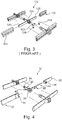
- Figure 3 shows a portion of a prior art chain 112 with connected flights 130.
- the chain 112 comprise a series of chain links 120, with adjacent chain links connected to each other by a connecting pin 122 held in place by circlips 124.
- a metal flight 130 is welded to each side of the chain link 120.
- a sleeve 132 is inserted over the metal flight.
- Figure 4 shows a portion of a chain 12 and flights 30,32 according to a first embodiment of the invention.
- the chain 12 comprise a series of chain links 20, and adjacent chain links are connected to each other by a connecting pin 22.
- a first flight 30 is positioned at a first side of the chain link 20 and a second flight 32 is positioned at a second side of the chain link 20.
- first reinforcing member 40 extends into the body of the first flight 30.
- the first reinforcing member 40 further extends away from the first flight 30, through the chain link 20 and into the body of the second flight 32.
- the first reinforcing member 40 is formed from a strong, stiff and tough material, for example forged steel.
- other forms of steel including extruded steel, stainless steel, high tensile rolled steel, coiled spring steel, and non-steel materials could also be used.
- the first reinforcing member 40 will experience only bending stresses in operation.
- the first reinforcing member 40 passes through a separate aperture 42 provided at the chain link 20.
- This aperture 42 is at a location spaced apart from, and in between, the two connection locations 26 for adjacent chain links 20. Therefore, any loading on the flights 30 is not directly transmitted to the connecting pin 22.
- the diameters of the first reinforcing member 40 and the aperture 42 are substantially equal so there is little or no clearance or play. This prevents or minimises any deviation of the first reinforcing member 40 from an axis normal to the plane of the aperture 42, and also assists in distributing loading.
- the arrangement according to the invention does not include any circlips 124. This is due to the profile of the flights 30 as explained below.
- the flights 30 are plastic and formed by moulding. This allows greater flexibility in the cross sectional profile of the flights 30. In the embodiment of Figure 4 , the thickness of each flight reduces towards each lateral edge of the flight 30. Such a profile provides good load bearing while reducing weight and the amount of material used.
- a bore is formed in each flight 30 during moulding.
- the first reinforcing member 40 extends into a bore of the flights 30 for a distance which is around a third of the length of the flights.
- the diameters of the first reinforcing member 40 and the bores are substantially equal and the flights are connected to the first reinforcing member 40 using an interference fit.
- the flights are formed with a shield portion 34.
- This portion extends from a major plane of the flights 30 towards the connection location 26 and adjacent to the chain link 20.
- the shield portion 34 includes a recess for receiving and retaining the connecting pin 22. This arrangement provides better retention of the connecting pin 22 and avoids the requirement for circlips. Also, the body of the flight 30 is thicker at its base to resist bending moments.
- FIG. 5 shows a portion of a chain 12 and flights according to a second embodiment of the invention and like features are given like reference numerals.
- the flights 30 are moulded with a second bore and the chain link 20 includes a second aperture for receiving the second reinforcing member 44.
- the flights have a modified profile.
- Each flight includes a thickened portion to accommodate each bore, as well as thinner portions. This geometry provides good bending strength while minimising on the amount of material used.
- Figure 6 shows an FEA model of the portion of the chain 12 and flights of the embodiment of Figure 5 .
- the applied load 102 represents the loading that the flights would experience when pushing the material 100.
- the flights experience bending and the bending deflection increases towards the free end of each flight.
- the plastic material can be selected with properties that do not result in rapid spring back when the load is removed.
- Figure 7 shows the Von Mises stress results from the FEA model of Figure 6 for the chain link 20 and reinforcing members 40, 44 in isolation. It can be seen that the stress is evenly distributed with no local stress concentrations.
- Figures 8 and 9 show the deflection results from the FEA model of Figure 6 for the chain link 20 and reinforcing members 40, 44 in isolation and with the flights respectively. The deflection progressively increases as the distance from the chain link 20 increases.
- the invention provides a number of advantages. For example, as well as improved load distribution, the type and amount of materials used result in weight savings. Depending on the chain length involved (a typical range is from 10 m to 40 m), there is a significant 33% to 40% weight saving. As the chain weight is reduced, less power is required to convey both the chain and material. This improves the mechanical efficiency of the chain conveyor device.
- the invention also provides material and manufacturing cost savings due, for example, to improved ease of manufacturing and a reduction in the number of parts.
Landscapes
- Engineering & Computer Science (AREA)
- Mechanical Engineering (AREA)
- Chain Conveyers (AREA)
- Structure Of Belt Conveyors (AREA)
Description
- The present invention relates to an improved chain conveyor device and to a method of assembling a chain conveyor device. In particular, but not exclusively, the invention relates to chain conveyor devices with improved load distribution and a reduced volume of material.
- A conveyor system is used as material handling equipment in many different industries. A common type of conveyor device is a chain conveyor which comprises an endless chain arrangement. Attached to the chain are a number of flights which push, pull or carry the load to be conveyed.
- Known chain conveyors typically comprise a series of chain links, with adjacent chain links connected to each other by a connecting pin held in place by circlips, and a metal flight extending from each side of the chain link. A sleeve may be inserted over the metal flight. However, the profile of the sleeve is limited by the substantial size of the flight.
- In many cases, the flights are attached by welding and are located separate and spaced from the connection of adjacent chain links. In other cases, the connection of adjacent chain links (the connecting pin and pin apertures of the chain links) are used to connect the flights. A flight is bolted to each side of the chain link using the pin aperture of the chain link and the connecting pin as the bolt.
- The flights conveying the material carry much of the load of the system, although this loading is transmitted to the connecting pin as a tensile force. This loading can be complex as there can be frequent changes of direction, both horizontally and vertically. These changes of direction can cause flexing of the entire length of the flights. Fatigue is a common failure mode. The flights may also spring back suddenly to impact and damage nearby equipment or the conveyed material.
- Each flight is a cantilever and the loading on the flight generates a moment which can produce a high separating force at the connection to the chain link. It is known that the welded connection represents a common source of failure. Consequently, the failed flight is unable to convey material and/or the sleeve can become separated from the flight.
- For devices that use the connection of adjacent chain links to connect the flights, complex loading on the flight can be transmitted to the chain link as a force other than the tensile force. Therefore, the chain link, connecting pin, or the circlips that retain the pin, can fail. Failure at the connection results in catastrophic failure of the entire device.
-
US 6, 662, 932 relates to a chain and flights conveyor with swivel links.US 6, 662, 932 discloses a first flight member located on a first lateral side of a chain link and having a first reinforcing member extending into the body of said first flight member, the first reinforcing member further extending away from the first flight member, through the chain link and into or along the body of a second flight member located on a second opposite lateral side of the chain. - It is desirable to provide an improved conveyor device which at least mitigates one or more of the above problems. It is desirable to provide an improved conveyor device in which the flight or flights are not provided as cantilevers. It is desirable to provide an improved conveyor device which provides a material weight saving.
- According to a first aspect of the present invention there is provided a chain conveyor device for material handling comprising:
- an endless chain comprising a series of chain links,
wherein adjacent chain links are connected to each other at a connection location; and - a first flight member located on a first lateral side of a chain link
and having a first reinforcing member extending into or along the body of the first flight member, - the first reinforcing member further extending away from the first flight member, through the chain link
- and into or along the body of a second flight member located on a second opposite lateral side of the chain link;and
- the first reinforcing member passing through the chain link at a location spaced apart from the connection location; and
- wherein the chain link has a connecting pin aperture at each end of the chain link (20) to allow connection to two adjacent chain links, and wherein the chain link (20) further includes a first reinforcing member aperture located between the two connecting pin apertures.
- The diameters of the first reinforcing member and the first reinforcing member aperture may be substantially equal.
- The first reinforcing member may extend into the first and second flight members a distance which is substantially less than the length of the first and second flight members. The first reinforcing member may extend into the first and second flight members a distance which is less than half the length of the first and second flight members.
- The body of each of the first and second flight members may include a bore for receiving the first reinforcing member. Alternatively, the first and second flight members may include means for coupling the first reinforcing member to the first and second flight members along at least a portion of their length. The coupling means may comprise fastening means for fastening the first reinforcing member to an exterior surface of the first and second flight members.
- The diameters of the first reinforcing member and the bore may be substantially equal.
- The first and second flight members may be formed from a plastic or composite material or the like. The first and second flight members may be formed by moulding.
- The cross sectional profile of the first and second flight members may include a thickened portion to accommodate the bore for the first reinforcing member. The profile may include one or more portions thinner than the bore diameter. The thickness of each flight member may taper down towards each lateral edge of the
flight member. Such a profile provides good load bearing while reducing weight and the amount of material used. - At least one of the first and second flight members may include a shield portion which extends from a major plane of the flight member towards a connection location. The shield portion may be adjacent to the chain link. The shield portion may include a recess for receiving and retaining the connecting pin that connects two adjacent chain links. Such an arrangement provides better retention of the connecting pin and avoids the requirement for circlips. Also, the body of the flight member is thicker at its base to resist bending moments.
- The first reinforcing member may be formed from a rigid material such as steel, particularly forged steel. The first reinforcing member may be cylindrical.
- The first flight member may include a second reinforcing member extending into the body of the first flight member and further extending away from the first flight member, through the chain link and into the body of the second flight member.
- The chain link may further include a second reinforcing member aperture located between the two connecting pin apertures.
- The first and second flight members may include a second bore for the second reinforcing member. The first and second flight members may include a second thickened portion to accommodate the second bore.
- According to a second aspect of the present invention there is provided a method of assembling a chain conveyor device for material handling, the method comprising:
- providing an endless chain comprising a series of chain links, wherein adjacent chain links are connected to each other at a connection location;
inserting a first reinforcing member into a first flight member such that the first reinforcing member extends into the body of the first flight member and a first portion of the first reinforcing member aperture extends away from the first flight member; - passing the first portion of the first reinforcing member through the chain link so that the first flight member is located on a first lateral side of a chain link and such that a second portion extends away from a second opposite lateral side of the chain link;
- inserting the second portion of the first reinforcing member into a second flight member such that the first reinforcing member extends into the body of the second flight member and such that the second flight member is located on a second opposite lateral side of the chain link; and
passing the first reinforcing member through the chain link at a location spaced apart from the connection location;
wherein the chain link has a connecting pin aperture at each end of the chain link to allow connection to two adjacent chain links, and wherein the chain link further includes a first reinforcing member aperture located between the two connecting pin apertures. - The method may include forming a bore at the first and second flight members and forming a first reinforcing member aperture at the chain link, both for receiving the first reinforcing member. The method may include forming the diameters of the first reinforcing member and the first reinforcing member aperture to be substantially equal.
- The method may include forming the diameters of the first reinforcing member and the bore to be substantially equal.
- The method may include retaining the first reinforcing member within one or both of the first reinforcing member aperture and the bore by an interference fit.
- The method may include inserting the first reinforcing member into the first and second flight members by a distance which is less than half the length of the first and second flight members.
- The method may include forming the first and second flight members from a plastic or composite material or the like. The first and second flight members may be formed by moulding.
- The method may include forming at least one of the first and second flight members to include a shield portion which extends from a major plane of the flight member towards a connection location. The method may include forming the shield portion to include a recess for receiving and retaining the connecting pin that connects two adjacent chain links.
- Embodiments of the present invention will now be described, by way of example only, with reference to the accompanying drawings in which:
-
Figure 1 is a perspective view of achain conveyor device 10 for material handling; -
Figure 2 is a perspective view of the housing of thechain conveyor device 10 and showing the movement of material; -
Figure 3 is an exploded perspective view of a portion of a prior art chain and flights; -
Figure 4 is an exploded perspective view of a portion of a chain and flights according to a first embodiment of the invention; -
Figure 5 is an exploded perspective view of a portion of a chain and flights according to a second embodiment of the invention; -
Figure 6 is a perspective view of an FEA model of the portion of chain and flights of the embodiment ofFigure 5 ; -
Figure 7 is a perspective view of the stress results from the FEA model ofFigure 6 for the chain link and reinforcing members in isolation; -
Figure 8 is a perspective view of the deflection results from the FEA model of -
Figure 6 for the chain link and reinforcing members in isolation; and -
Figure 9 is a perspective view of the deflection results from the FEA model of -
Figure 6 for the chain link, reinforcing members and flights. -
Figure 1 shows achain conveyor device 10 for material handling. Thedevice 10 comprises anendless chain 12 formed by a series of connected chain links 20 and an arrangement offlights 30 connected to the chain links 20 for moving thematerial 100. Thechain 12 and connectedflights 30 are provided within ahousing 14. Thehousing 14 includes aninlet 16 for receivingmaterial 100 at a first location and anoutlet 18 for discharging thematerial 100 at a second location. This movement ofmaterial 100 is shown inFigure 2 . -
Figure 3 shows a portion of aprior art chain 112 withconnected flights 130. Thechain 112 comprise a series ofchain links 120, with adjacent chain links connected to each other by a connectingpin 122 held in place bycirclips 124. Ametal flight 130 is welded to each side of thechain link 120. Asleeve 132 is inserted over the metal flight. -
Figure 4 shows a portion of achain 12 andflights chain 12 comprise a series of chain links 20, and adjacent chain links are connected to each other by a connectingpin 22. Afirst flight 30 is positioned at a first side of thechain link 20 and asecond flight 32 is positioned at a second side of thechain link 20. - However, rather than using welding (or the
connection point 26 for adjacent chain links) a first reinforcingmember 40 extends into the body of thefirst flight 30. The first reinforcingmember 40 further extends away from thefirst flight 30, through thechain link 20 and into the body of thesecond flight 32. The first reinforcingmember 40 is formed from a strong, stiff and tough material, for example forged steel. However, other forms of steel, including extruded steel, stainless steel, high tensile rolled steel, coiled spring steel, and non-steel materials could also be used. - Therefore, rather than being a cantilever like the prior art flights, the first reinforcing
member 40 will experience only bending stresses in operation. - The first reinforcing
member 40 passes through aseparate aperture 42 provided at thechain link 20. Thisaperture 42 is at a location spaced apart from, and in between, the twoconnection locations 26 for adjacent chain links 20. Therefore, any loading on theflights 30 is not directly transmitted to the connectingpin 22. Also, the diameters of the first reinforcingmember 40 and theaperture 42 are substantially equal so there is little or no clearance or play. This prevents or minimises any deviation of the first reinforcingmember 40 from an axis normal to the plane of theaperture 42, and also assists in distributing loading. - Also, it can be seen that the arrangement according to the invention does not include any
circlips 124. This is due to the profile of theflights 30 as explained below. - The
flights 30 are plastic and formed by moulding. This allows greater flexibility in the cross sectional profile of theflights 30. In the embodiment ofFigure 4 , the thickness of each flight reduces towards each lateral edge of theflight 30. Such a profile provides good load bearing while reducing weight and the amount of material used. - A bore is formed in each
flight 30 during moulding. The first reinforcingmember 40 extends into a bore of theflights 30 for a distance which is around a third of the length of the flights. The diameters of the first reinforcingmember 40 and the bores are substantially equal and the flights are connected to the first reinforcingmember 40 using an interference fit. - During moulding, the flights are formed with a
shield portion 34. This portion extends from a major plane of theflights 30 towards theconnection location 26 and adjacent to thechain link 20. Theshield portion 34 includes a recess for receiving and retaining the connectingpin 22. This arrangement provides better retention of the connectingpin 22 and avoids the requirement for circlips. Also, the body of theflight 30 is thicker at its base to resist bending moments. -
Figure 5 shows a portion of achain 12 and flights according to a second embodiment of the invention and like features are given like reference numerals. In this embodiment, there are two reinforcing members for increased strength and rigidity. Theflights 30 are moulded with a second bore and thechain link 20 includes a second aperture for receiving the second reinforcingmember 44. Also, in this embodiment, the flights have a modified profile. Each flight includes a thickened portion to accommodate each bore, as well as thinner portions. This geometry provides good bending strength while minimising on the amount of material used. - It has been found that the arrangement according to the invention provides excellent performance in terms of distribution of loading and stresses, greater rigidity and greater strength (withstanding a higher load before failure). This has been verified using Finite Element Analysis (FEA).
- For instance,
Figure 6 shows an FEA model of the portion of thechain 12 and flights of the embodiment ofFigure 5 . In the model, the appliedload 102 represents the loading that the flights would experience when pushing thematerial 100. The flights experience bending and the bending deflection increases towards the free end of each flight. - This deflection is useful as it helps to accommodate changes of direction of the conveyor system and absorbs energy. A more rigid structure would experience greater stress at the
chain link 20. This is why the first reinforcingmember 40 only extends into the flights for about a third of the length of the flights. However, the plastic material can be selected with properties that do not result in rapid spring back when the load is removed. -
Figure 7 shows the Von Mises stress results from the FEA model ofFigure 6 for thechain link 20 and reinforcingmembers -
Figures 8 and 9 show the deflection results from the FEA model ofFigure 6 for thechain link 20 and reinforcingmembers chain link 20 increases. - The invention provides a number of advantages. For example, as well as improved load distribution, the type and amount of materials used result in weight savings. Depending on the chain length involved (a typical range is from 10 m to 40 m), there is a significant 33% to 40% weight saving. As the chain weight is reduced, less power is required to convey both the chain and material. This improves the mechanical efficiency of the chain conveyor device.
- The invention also provides material and manufacturing cost savings due, for example, to improved ease of manufacturing and a reduction in the number of parts.
- Whilst specific embodiments of the present invention have been described above, it will be appreciated that departures from the described embodiments may still fall within the scope of the present invention, which is defined by the appended claims.
Claims (14)
- A chain conveyor device (10) for material handling comprising:an endless chain (12) comprising a series of chain links (20),
wherein adjacent chain links are connected to each other at a connection location (26); anda first flight member (30) located on a first lateral side of a chain link (20) and having a first reinforcing member (40) extending into or along the body of the first flight member (30),the first reinforcing member (40) further extending away from the first flight member (30), through the chain link (20)and into or along the body of a second flight member (32) located on a second opposite lateral side of the chain link (20);andthe first reinforcing member (40) passing through the chain link (20) at a location spaced apart from the connection location (26); andwherein the chain link (20) has a connecting pin aperture at each end of the chain link (20) to allow connection to two adjacent chain links, and wherein the chain link (20) further includes a first reinforcing member aperture (42) located between the two connecting pin apertures. - A device (10) as claimed in claim 1, wherein the diameters of the first reinforcing member (40) and the first reinforcing member aperture (42) are substantially equal; and optionally wherein the first reinforcing member (40) extends into or along the first and second flight members (30,32) a distance which is substantially less than the length of the first and second flight members (30, 32); and optionally wherein the first reinforcing member (40) extends into or along the first and second flight members (30, 32) a distance which is less than half the length of the first and second flight members (30, 32).
- A device (10) as claimed in any preceding claim, wherein the body of each of the first and second flight members (30, 32) includes a bore for receiving the first reinforcing member (40); and optionally wherein the diameters of the first reinforcing member (40) and the bore are substantially equal.
- A device (10) as claimed in any preceding claim, wherein the first and second flight members (30, 32) are formed from a plastic or composite material; and optionally wherein the first and second flight members (30, 32) are formed by moulding.
- A device (10) as claimed in claim 3 or claim 4 when dependent on claim 3, wherein the cross sectional profile of the first and second flight members (30, 32) includes a thickened portion to accommodate the bore for the first reinforcing member (40).
- A device (10) as claimed in claim 3 or any of claims 4 and 5 when dependent on claim 3, wherein the profile includes one or more portions thinner than the bore diameter.
- A device (10) as claimed in any preceding claim, wherein the thickness of each flight member tapers down towards each lateral edge of the flight member.
- A device (10) as claimed in any preceding claim, wherein at least one of the first and second flight members (30, 32) includes a shield portion (34) which extends from a major plane of the flight member towards a connection location; and optionally wherein the shield portion (34) is adjacent to the chain link (20); and optionally wherein the shield portion (34) includes a recess for receiving and retaining the connecting pin (22) that connects two adjacent chain links.
- A device (10) as claimed in claim 1, wherein the first flight member (30) includes a second reinforcing member (44) extending into the body of the first flight member (30) and further extending away from the first flight member (30), through the chain link (20) and into the body of the second flight member (32); and optionally wherein the chain link (20) includes a second reinforcing member aperture located between the two connecting pin apertures; and optionally wherein the first and second flight members (30, 32) include a second bore for the second reinforcing member (44).
- A method of assembling a chain conveyor device (10) for material handling, the method comprising:providing an endless chain (12) comprising a series of chain links (20),
wherein adjacent chain links are connected to each other at a connection location (26);inserting a first reinforcing member (40) into a first flight member (30) such that the first reinforcing member (40) extends into the body of the first flight member (30) and a first portion of the first reinforcing member aperture extends away from the first flight member (30);passing the first portion of the first reinforcing member (40) through the chain link (20) so that the first flight member (30) is located on a first lateral side of a chain link (20) and such that a second portion extends away from a second opposite lateral side of the chain link (20);inserting the second portion of the first reinforcing member (40) into a second flight member (32) such that the first reinforcing member (40) extends into the body of the second flight member (32) and such that the second flight member (32) is located on a second opposite lateral side of the chain link (20); andpassing the first reinforcing member (40) through the chain link (20) at a location spaced apart from the connection location (26);wherein the chain link (20) has a connecting pin aperture at each end of the chain link (20) to allow connection to two adjacent chain links, and wherein the chain link (20) further includes a first reinforcing member aperture located between the two connecting pin apertures. - A method as claimed in claim 10, including forming a bore at the first and second flight members (30, 32) and forming a first reinforcing member aperture at the chain link (20), both for receiving the first reinforcing member (40); and optionally including forming the diameters of the first reinforcing member (40) and the first reinforcing member aperture (42) to be substantially equal.
- A method as claimed in claim 11, including retaining the first reinforcing member (40) within one or both of the first reinforcing member aperture (42) and the bore by an interference fit; and optionally including inserting the first reinforcing member (40) into the first and second flight members (30, 32) by a distance which is less than half the length of the first and second flight members (30, 32).
- A method as claimed in any of claims 10 to 12, including forming the first and second flight members (30, 32) from a plastic or composite material.
- A method as claimed in any of claims 10 to 13, including forming at least one of the first and second flight members (30, 32) to include a shield portion (34) which extends from a major plane of the flight member towards a connection location and optionally including forming the shield portion (34) to include a recess for receiving and retaining a connecting pin (22) that connects two adjacent chain links.
Applications Claiming Priority (2)
| Application Number | Priority Date | Filing Date | Title |
|---|---|---|---|
| GBGB1221300.5A GB201221300D0 (en) | 2012-11-27 | 2012-11-27 | chain conveyor device |
| PCT/GB2013/053126 WO2014083329A1 (en) | 2012-11-27 | 2013-11-26 | Chain conveyor device |
Publications (2)
| Publication Number | Publication Date |
|---|---|
| EP2925644A1 EP2925644A1 (en) | 2015-10-07 |
| EP2925644B1 true EP2925644B1 (en) | 2018-03-07 |
Family
ID=47560728
Family Applications (1)
| Application Number | Title | Priority Date | Filing Date |
|---|---|---|---|
| EP13796158.7A Not-in-force EP2925644B1 (en) | 2012-11-27 | 2013-11-26 | Chain conveyor device |
Country Status (6)
| Country | Link |
|---|---|
| US (1) | US20150314963A1 (en) |
| EP (1) | EP2925644B1 (en) |
| CN (1) | CN104870339B (en) |
| BR (1) | BR112015011926A2 (en) |
| GB (2) | GB201221300D0 (en) |
| WO (1) | WO2014083329A1 (en) |
Families Citing this family (3)
| Publication number | Priority date | Publication date | Assignee | Title |
|---|---|---|---|---|
| WO2020040884A1 (en) * | 2018-08-22 | 2020-02-27 | Flexicon Corporation | Tubular cable conveyor slug with integrated connector |
| US11280291B2 (en) * | 2019-12-31 | 2022-03-22 | Mahle International Gmbh | Cylinder liner with temperature sensor |
| DE102021106744B4 (en) * | 2021-03-19 | 2024-02-01 | Schenck Process Europe Gmbh | Chain link as well as plate chain and chain conveyor |
Citations (1)
| Publication number | Priority date | Publication date | Assignee | Title |
|---|---|---|---|---|
| DE19633298A1 (en) * | 1996-08-19 | 1998-02-26 | Buehler Ag | Food processing plant conveyer chain has stabiliser rods covered by push-fit |
Family Cites Families (7)
| Publication number | Priority date | Publication date | Assignee | Title |
|---|---|---|---|---|
| US2761548A (en) * | 1955-06-24 | 1956-09-04 | Long Company | Scraper flight and built-up conveyor chain and flight combination |
| US3225897A (en) * | 1962-10-17 | 1965-12-28 | Lester G Rollins | Conveyor device |
| US4766995A (en) * | 1986-09-03 | 1988-08-30 | The Cincinnati Mine Machinery Company | Pusher-type conveyor chain |
| US6662932B1 (en) * | 2003-06-01 | 2003-12-16 | Joy Mm Delaware, Inc. | Chain and flight conveyor with swivel links |
| US7080728B2 (en) * | 2004-09-11 | 2006-07-25 | 4B Elevator Components, Ltd. | Forged chain and flight assembly and method of making same |
| US8453826B2 (en) * | 2008-09-22 | 2013-06-04 | The Cincinnati Mine Machinery Company | Conveyor chain |
| US8141696B2 (en) * | 2009-04-30 | 2012-03-27 | Joy Mm Delaware, Inc. | Replaceable sound dampening conveyor chain flight |
-
2012
- 2012-11-27 GB GBGB1221300.5A patent/GB201221300D0/en not_active Ceased
-
2013
- 2013-11-26 GB GB1410738.7A patent/GB2510789B/en not_active Expired - Fee Related
- 2013-11-26 WO PCT/GB2013/053126 patent/WO2014083329A1/en not_active Ceased
- 2013-11-26 EP EP13796158.7A patent/EP2925644B1/en not_active Not-in-force
- 2013-11-26 BR BR112015011926A patent/BR112015011926A2/en not_active IP Right Cessation
- 2013-11-26 CN CN201380061867.1A patent/CN104870339B/en not_active Expired - Fee Related
- 2013-11-26 US US14/647,559 patent/US20150314963A1/en not_active Abandoned
Patent Citations (1)
| Publication number | Priority date | Publication date | Assignee | Title |
|---|---|---|---|---|
| DE19633298A1 (en) * | 1996-08-19 | 1998-02-26 | Buehler Ag | Food processing plant conveyer chain has stabiliser rods covered by push-fit |
Also Published As
| Publication number | Publication date |
|---|---|
| EP2925644A1 (en) | 2015-10-07 |
| GB201221300D0 (en) | 2013-01-09 |
| CN104870339B (en) | 2017-08-25 |
| GB2510789A (en) | 2014-08-13 |
| US20150314963A1 (en) | 2015-11-05 |
| CN104870339A (en) | 2015-08-26 |
| BR112015011926A2 (en) | 2017-07-11 |
| GB2510789B (en) | 2016-02-24 |
| WO2014083329A1 (en) | 2014-06-05 |
| GB201410738D0 (en) | 2014-07-30 |
Similar Documents
| Publication | Publication Date | Title |
|---|---|---|
| US9033139B2 (en) | Rod belt for a rod belt conveyor for agricultural machinery | |
| AU2016308737B2 (en) | Bar pin bushing for vehicle suspension and corresponding mounting method | |
| US8591345B2 (en) | Flexible diaphragm coupling for axial force loading | |
| US8074438B2 (en) | Link chain | |
| US8905880B2 (en) | Chain connecting pin | |
| CN102439343B (en) | Protective sleeve for a flexible pipe | |
| US20090218882A1 (en) | Tracks For Track Laying Vehicles And Vehicles Carrying Such Tracks | |
| EP2805899B1 (en) | Transport chain & transport chain system | |
| US20150314963A1 (en) | Chain conveyor device | |
| CN101875433B (en) | Replaceable sound dampening conveyor chain flight | |
| EP3153404B1 (en) | Aircraft assembly | |
| CN105051412B (en) | the chain | |
| US4327995A (en) | Bar pin for use in torque rods | |
| EP2787247B1 (en) | Link for chain connection | |
| EP3713860B1 (en) | Tubular cable conveyor slug with integrated connector | |
| EP0514596A1 (en) | Fitting assembly for a composite structure | |
| EP3643600B1 (en) | Bulkhead joint assembly | |
| JP6195283B2 (en) | Steel shell segment joint structure | |
| CN105518313B (en) | Equipment for connection section bar element | |
| CN211949642U (en) | Supporting structure and arm support material conveying equipment | |
| Shahane et al. | Design and analysis of chain outer link by using composite material | |
| DE102012003287A1 (en) | rotary pistons | |
| CN112513496A (en) | Articulated chain |
Legal Events
| Date | Code | Title | Description |
|---|---|---|---|
| PUAI | Public reference made under article 153(3) epc to a published international application that has entered the european phase |
Free format text: ORIGINAL CODE: 0009012 |
|
| 17P | Request for examination filed |
Effective date: 20150602 |
|
| AK | Designated contracting states |
Kind code of ref document: A1 Designated state(s): AL AT BE BG CH CY CZ DE DK EE ES FI FR GB GR HR HU IE IS IT LI LT LU LV MC MK MT NL NO PL PT RO RS SE SI SK SM TR |
|
| AX | Request for extension of the european patent |
Extension state: BA ME |
|
| DAX | Request for extension of the european patent (deleted) | ||
| 17Q | First examination report despatched |
Effective date: 20160517 |
|
| RAP1 | Party data changed (applicant data changed or rights of an application transferred) |
Owner name: SCHENCK PROCESS UK LIMITED |
|
| GRAP | Despatch of communication of intention to grant a patent |
Free format text: ORIGINAL CODE: EPIDOSNIGR1 |
|
| INTG | Intention to grant announced |
Effective date: 20171024 |
|
| GRAS | Grant fee paid |
Free format text: ORIGINAL CODE: EPIDOSNIGR3 |
|
| GRAA | (expected) grant |
Free format text: ORIGINAL CODE: 0009210 |
|
| AK | Designated contracting states |
Kind code of ref document: B1 Designated state(s): AL AT BE BG CH CY CZ DE DK EE ES FI FR GB GR HR HU IE IS IT LI LT LU LV MC MK MT NL NO PL PT RO RS SE SI SK SM TR |
|
| REG | Reference to a national code |
Ref country code: GB Ref legal event code: FG4D |
|
| REG | Reference to a national code |
Ref country code: CH Ref legal event code: EP Ref country code: AT Ref legal event code: REF Ref document number: 976301 Country of ref document: AT Kind code of ref document: T Effective date: 20180315 |
|
| REG | Reference to a national code |
Ref country code: IE Ref legal event code: FG4D |
|
| REG | Reference to a national code |
Ref country code: DE Ref legal event code: R096 Ref document number: 602013034130 Country of ref document: DE |
|
| REG | Reference to a national code |
Ref country code: NL Ref legal event code: MP Effective date: 20180307 |
|
| REG | Reference to a national code |
Ref country code: LT Ref legal event code: MG4D |
|
| PG25 | Lapsed in a contracting state [announced via postgrant information from national office to epo] |
Ref country code: NO Free format text: LAPSE BECAUSE OF FAILURE TO SUBMIT A TRANSLATION OF THE DESCRIPTION OR TO PAY THE FEE WITHIN THE PRESCRIBED TIME-LIMIT Effective date: 20180607 Ref country code: ES Free format text: LAPSE BECAUSE OF FAILURE TO SUBMIT A TRANSLATION OF THE DESCRIPTION OR TO PAY THE FEE WITHIN THE PRESCRIBED TIME-LIMIT Effective date: 20180307 Ref country code: HR Free format text: LAPSE BECAUSE OF FAILURE TO SUBMIT A TRANSLATION OF THE DESCRIPTION OR TO PAY THE FEE WITHIN THE PRESCRIBED TIME-LIMIT Effective date: 20180307 Ref country code: LT Free format text: LAPSE BECAUSE OF FAILURE TO SUBMIT A TRANSLATION OF THE DESCRIPTION OR TO PAY THE FEE WITHIN THE PRESCRIBED TIME-LIMIT Effective date: 20180307 Ref country code: CY Free format text: LAPSE BECAUSE OF FAILURE TO SUBMIT A TRANSLATION OF THE DESCRIPTION OR TO PAY THE FEE WITHIN THE PRESCRIBED TIME-LIMIT Effective date: 20180307 Ref country code: FI Free format text: LAPSE BECAUSE OF FAILURE TO SUBMIT A TRANSLATION OF THE DESCRIPTION OR TO PAY THE FEE WITHIN THE PRESCRIBED TIME-LIMIT Effective date: 20180307 |
|
| REG | Reference to a national code |
Ref country code: AT Ref legal event code: MK05 Ref document number: 976301 Country of ref document: AT Kind code of ref document: T Effective date: 20180307 |
|
| PG25 | Lapsed in a contracting state [announced via postgrant information from national office to epo] |
Ref country code: BG Free format text: LAPSE BECAUSE OF FAILURE TO SUBMIT A TRANSLATION OF THE DESCRIPTION OR TO PAY THE FEE WITHIN THE PRESCRIBED TIME-LIMIT Effective date: 20180607 Ref country code: GR Free format text: LAPSE BECAUSE OF FAILURE TO SUBMIT A TRANSLATION OF THE DESCRIPTION OR TO PAY THE FEE WITHIN THE PRESCRIBED TIME-LIMIT Effective date: 20180608 Ref country code: SE Free format text: LAPSE BECAUSE OF FAILURE TO SUBMIT A TRANSLATION OF THE DESCRIPTION OR TO PAY THE FEE WITHIN THE PRESCRIBED TIME-LIMIT Effective date: 20180307 Ref country code: LV Free format text: LAPSE BECAUSE OF FAILURE TO SUBMIT A TRANSLATION OF THE DESCRIPTION OR TO PAY THE FEE WITHIN THE PRESCRIBED TIME-LIMIT Effective date: 20180307 Ref country code: RS Free format text: LAPSE BECAUSE OF FAILURE TO SUBMIT A TRANSLATION OF THE DESCRIPTION OR TO PAY THE FEE WITHIN THE PRESCRIBED TIME-LIMIT Effective date: 20180307 |
|
| PG25 | Lapsed in a contracting state [announced via postgrant information from national office to epo] |
Ref country code: EE Free format text: LAPSE BECAUSE OF FAILURE TO SUBMIT A TRANSLATION OF THE DESCRIPTION OR TO PAY THE FEE WITHIN THE PRESCRIBED TIME-LIMIT Effective date: 20180307 Ref country code: PL Free format text: LAPSE BECAUSE OF FAILURE TO SUBMIT A TRANSLATION OF THE DESCRIPTION OR TO PAY THE FEE WITHIN THE PRESCRIBED TIME-LIMIT Effective date: 20180307 Ref country code: IT Free format text: LAPSE BECAUSE OF FAILURE TO SUBMIT A TRANSLATION OF THE DESCRIPTION OR TO PAY THE FEE WITHIN THE PRESCRIBED TIME-LIMIT Effective date: 20180307 Ref country code: AL Free format text: LAPSE BECAUSE OF FAILURE TO SUBMIT A TRANSLATION OF THE DESCRIPTION OR TO PAY THE FEE WITHIN THE PRESCRIBED TIME-LIMIT Effective date: 20180307 Ref country code: RO Free format text: LAPSE BECAUSE OF FAILURE TO SUBMIT A TRANSLATION OF THE DESCRIPTION OR TO PAY THE FEE WITHIN THE PRESCRIBED TIME-LIMIT Effective date: 20180307 Ref country code: NL Free format text: LAPSE BECAUSE OF FAILURE TO SUBMIT A TRANSLATION OF THE DESCRIPTION OR TO PAY THE FEE WITHIN THE PRESCRIBED TIME-LIMIT Effective date: 20180307 |
|
| PG25 | Lapsed in a contracting state [announced via postgrant information from national office to epo] |
Ref country code: AT Free format text: LAPSE BECAUSE OF FAILURE TO SUBMIT A TRANSLATION OF THE DESCRIPTION OR TO PAY THE FEE WITHIN THE PRESCRIBED TIME-LIMIT Effective date: 20180307 Ref country code: SM Free format text: LAPSE BECAUSE OF FAILURE TO SUBMIT A TRANSLATION OF THE DESCRIPTION OR TO PAY THE FEE WITHIN THE PRESCRIBED TIME-LIMIT Effective date: 20180307 Ref country code: SK Free format text: LAPSE BECAUSE OF FAILURE TO SUBMIT A TRANSLATION OF THE DESCRIPTION OR TO PAY THE FEE WITHIN THE PRESCRIBED TIME-LIMIT Effective date: 20180307 |
|
| REG | Reference to a national code |
Ref country code: DE Ref legal event code: R097 Ref document number: 602013034130 Country of ref document: DE |
|
| PG25 | Lapsed in a contracting state [announced via postgrant information from national office to epo] |
Ref country code: PT Free format text: LAPSE BECAUSE OF FAILURE TO SUBMIT A TRANSLATION OF THE DESCRIPTION OR TO PAY THE FEE WITHIN THE PRESCRIBED TIME-LIMIT Effective date: 20180709 |
|
| PLBE | No opposition filed within time limit |
Free format text: ORIGINAL CODE: 0009261 |
|
| STAA | Information on the status of an ep patent application or granted ep patent |
Free format text: STATUS: NO OPPOSITION FILED WITHIN TIME LIMIT |
|
| PG25 | Lapsed in a contracting state [announced via postgrant information from national office to epo] |
Ref country code: DK Free format text: LAPSE BECAUSE OF FAILURE TO SUBMIT A TRANSLATION OF THE DESCRIPTION OR TO PAY THE FEE WITHIN THE PRESCRIBED TIME-LIMIT Effective date: 20180307 |
|
| 26N | No opposition filed |
Effective date: 20181210 |
|
| PG25 | Lapsed in a contracting state [announced via postgrant information from national office to epo] |
Ref country code: SI Free format text: LAPSE BECAUSE OF FAILURE TO SUBMIT A TRANSLATION OF THE DESCRIPTION OR TO PAY THE FEE WITHIN THE PRESCRIBED TIME-LIMIT Effective date: 20180307 |
|
| REG | Reference to a national code |
Ref country code: DE Ref legal event code: R119 Ref document number: 602013034130 Country of ref document: DE |
|
| REG | Reference to a national code |
Ref country code: CH Ref legal event code: PL |
|
| GBPC | Gb: european patent ceased through non-payment of renewal fee |
Effective date: 20181126 |
|
| PG25 | Lapsed in a contracting state [announced via postgrant information from national office to epo] |
Ref country code: LU Free format text: LAPSE BECAUSE OF NON-PAYMENT OF DUE FEES Effective date: 20181126 Ref country code: CZ Free format text: LAPSE BECAUSE OF NON-PAYMENT OF DUE FEES Effective date: 20181126 Ref country code: MC Free format text: LAPSE BECAUSE OF FAILURE TO SUBMIT A TRANSLATION OF THE DESCRIPTION OR TO PAY THE FEE WITHIN THE PRESCRIBED TIME-LIMIT Effective date: 20180307 |
|
| REG | Reference to a national code |
Ref country code: BE Ref legal event code: MM Effective date: 20181130 |
|
| REG | Reference to a national code |
Ref country code: IE Ref legal event code: MM4A |
|
| PG25 | Lapsed in a contracting state [announced via postgrant information from national office to epo] |
Ref country code: LI Free format text: LAPSE BECAUSE OF NON-PAYMENT OF DUE FEES Effective date: 20181130 Ref country code: CH Free format text: LAPSE BECAUSE OF NON-PAYMENT OF DUE FEES Effective date: 20181130 |
|
| PG25 | Lapsed in a contracting state [announced via postgrant information from national office to epo] |
Ref country code: FR Free format text: LAPSE BECAUSE OF NON-PAYMENT OF DUE FEES Effective date: 20181130 Ref country code: IE Free format text: LAPSE BECAUSE OF NON-PAYMENT OF DUE FEES Effective date: 20181126 Ref country code: DE Free format text: LAPSE BECAUSE OF NON-PAYMENT OF DUE FEES Effective date: 20190601 |
|
| PG25 | Lapsed in a contracting state [announced via postgrant information from national office to epo] |
Ref country code: BE Free format text: LAPSE BECAUSE OF NON-PAYMENT OF DUE FEES Effective date: 20181130 |
|
| PG25 | Lapsed in a contracting state [announced via postgrant information from national office to epo] |
Ref country code: GB Free format text: LAPSE BECAUSE OF NON-PAYMENT OF DUE FEES Effective date: 20181126 |
|
| PG25 | Lapsed in a contracting state [announced via postgrant information from national office to epo] |
Ref country code: MT Free format text: LAPSE BECAUSE OF NON-PAYMENT OF DUE FEES Effective date: 20181126 |
|
| PG25 | Lapsed in a contracting state [announced via postgrant information from national office to epo] |
Ref country code: TR Free format text: LAPSE BECAUSE OF FAILURE TO SUBMIT A TRANSLATION OF THE DESCRIPTION OR TO PAY THE FEE WITHIN THE PRESCRIBED TIME-LIMIT Effective date: 20180307 |
|
| PG25 | Lapsed in a contracting state [announced via postgrant information from national office to epo] |
Ref country code: HU Free format text: LAPSE BECAUSE OF FAILURE TO SUBMIT A TRANSLATION OF THE DESCRIPTION OR TO PAY THE FEE WITHIN THE PRESCRIBED TIME-LIMIT; INVALID AB INITIO Effective date: 20131126 Ref country code: MK Free format text: LAPSE BECAUSE OF NON-PAYMENT OF DUE FEES Effective date: 20180307 |
|
| PG25 | Lapsed in a contracting state [announced via postgrant information from national office to epo] |
Ref country code: IS Free format text: LAPSE BECAUSE OF FAILURE TO SUBMIT A TRANSLATION OF THE DESCRIPTION OR TO PAY THE FEE WITHIN THE PRESCRIBED TIME-LIMIT Effective date: 20180707 |