EP2925503B1 - Appareil et procédé de régulation d'écoulement pour moulage par injection - Google Patents
Appareil et procédé de régulation d'écoulement pour moulage par injection Download PDFInfo
- Publication number
- EP2925503B1 EP2925503B1 EP13811661.1A EP13811661A EP2925503B1 EP 2925503 B1 EP2925503 B1 EP 2925503B1 EP 13811661 A EP13811661 A EP 13811661A EP 2925503 B1 EP2925503 B1 EP 2925503B1
- Authority
- EP
- European Patent Office
- Prior art keywords
- valve
- valve system
- pin
- drive
- rate
- Prior art date
- Legal status (The legal status is an assumption and is not a legal conclusion. Google has not performed a legal analysis and makes no representation as to the accuracy of the status listed.)
- Not-in-force
Links
- 238000000034 method Methods 0.000 title claims description 20
- 238000001746 injection moulding Methods 0.000 title claims description 16
- 239000012530 fluid Substances 0.000 claims description 147
- 238000011144 upstream manufacturing Methods 0.000 claims description 118
- 239000000463 material Substances 0.000 claims description 78
- 238000002347 injection Methods 0.000 claims description 63
- 239000007924 injection Substances 0.000 claims description 63
- 230000007246 mechanism Effects 0.000 claims description 12
- 230000004044 response Effects 0.000 claims description 4
- 101100282455 Arabidopsis thaliana AMP1 gene Proteins 0.000 description 9
- 101100218464 Haloarcula sp. (strain arg-2 / Andes heights) cop2 gene Proteins 0.000 description 9
- 230000006870 function Effects 0.000 description 3
- 101100285389 Arabidopsis thaliana HLS1 gene Proteins 0.000 description 2
- 101150030345 COP3 gene Proteins 0.000 description 2
- 238000004891 communication Methods 0.000 description 2
- 230000000295 complement effect Effects 0.000 description 2
- 230000007547 defect Effects 0.000 description 2
- 230000005672 electromagnetic field Effects 0.000 description 2
- 238000012544 monitoring process Methods 0.000 description 2
- 238000000465 moulding Methods 0.000 description 2
- 230000008569 process Effects 0.000 description 2
- 230000011664 signaling Effects 0.000 description 2
- 238000013459 approach Methods 0.000 description 1
- 238000001816 cooling Methods 0.000 description 1
- 238000013461 design Methods 0.000 description 1
- 230000000977 initiatory effect Effects 0.000 description 1
- 239000007788 liquid Substances 0.000 description 1
- 239000000203 mixture Substances 0.000 description 1
- 239000012768 molten material Substances 0.000 description 1
- 230000003287 optical effect Effects 0.000 description 1
- 229920000642 polymer Polymers 0.000 description 1
- 238000012545 processing Methods 0.000 description 1
Images


Classifications
-
- B—PERFORMING OPERATIONS; TRANSPORTING
- B29—WORKING OF PLASTICS; WORKING OF SUBSTANCES IN A PLASTIC STATE IN GENERAL
- B29C—SHAPING OR JOINING OF PLASTICS; SHAPING OF MATERIAL IN A PLASTIC STATE, NOT OTHERWISE PROVIDED FOR; AFTER-TREATMENT OF THE SHAPED PRODUCTS, e.g. REPAIRING
- B29C45/00—Injection moulding, i.e. forcing the required volume of moulding material through a nozzle into a closed mould; Apparatus therefor
- B29C45/17—Component parts, details or accessories; Auxiliary operations
- B29C45/76—Measuring, controlling or regulating
- B29C45/77—Measuring, controlling or regulating of velocity or pressure of moulding material
-
- B—PERFORMING OPERATIONS; TRANSPORTING
- B29—WORKING OF PLASTICS; WORKING OF SUBSTANCES IN A PLASTIC STATE IN GENERAL
- B29C—SHAPING OR JOINING OF PLASTICS; SHAPING OF MATERIAL IN A PLASTIC STATE, NOT OTHERWISE PROVIDED FOR; AFTER-TREATMENT OF THE SHAPED PRODUCTS, e.g. REPAIRING
- B29C45/00—Injection moulding, i.e. forcing the required volume of moulding material through a nozzle into a closed mould; Apparatus therefor
- B29C45/17—Component parts, details or accessories; Auxiliary operations
- B29C45/26—Moulds
- B29C45/27—Sprue channels ; Runner channels or runner nozzles
- B29C45/28—Closure devices therefor
- B29C45/2806—Closure devices therefor consisting of needle valve systems
- B29C45/281—Drive means therefor
-
- B—PERFORMING OPERATIONS; TRANSPORTING
- B29—WORKING OF PLASTICS; WORKING OF SUBSTANCES IN A PLASTIC STATE IN GENERAL
- B29C—SHAPING OR JOINING OF PLASTICS; SHAPING OF MATERIAL IN A PLASTIC STATE, NOT OTHERWISE PROVIDED FOR; AFTER-TREATMENT OF THE SHAPED PRODUCTS, e.g. REPAIRING
- B29C45/00—Injection moulding, i.e. forcing the required volume of moulding material through a nozzle into a closed mould; Apparatus therefor
- B29C45/17—Component parts, details or accessories; Auxiliary operations
- B29C45/76—Measuring, controlling or regulating
- B29C45/82—Hydraulic or pneumatic circuits
-
- B—PERFORMING OPERATIONS; TRANSPORTING
- B29—WORKING OF PLASTICS; WORKING OF SUBSTANCES IN A PLASTIC STATE IN GENERAL
- B29C—SHAPING OR JOINING OF PLASTICS; SHAPING OF MATERIAL IN A PLASTIC STATE, NOT OTHERWISE PROVIDED FOR; AFTER-TREATMENT OF THE SHAPED PRODUCTS, e.g. REPAIRING
- B29C45/00—Injection moulding, i.e. forcing the required volume of moulding material through a nozzle into a closed mould; Apparatus therefor
- B29C45/0025—Preventing defects on the moulded article, e.g. weld lines, shrinkage marks
- B29C2045/0032—Preventing defects on the moulded article, e.g. weld lines, shrinkage marks sequential injection from multiple gates, e.g. to avoid weld lines
-
- B—PERFORMING OPERATIONS; TRANSPORTING
- B29—WORKING OF PLASTICS; WORKING OF SUBSTANCES IN A PLASTIC STATE IN GENERAL
- B29C—SHAPING OR JOINING OF PLASTICS; SHAPING OF MATERIAL IN A PLASTIC STATE, NOT OTHERWISE PROVIDED FOR; AFTER-TREATMENT OF THE SHAPED PRODUCTS, e.g. REPAIRING
- B29C45/00—Injection moulding, i.e. forcing the required volume of moulding material through a nozzle into a closed mould; Apparatus therefor
- B29C45/17—Component parts, details or accessories; Auxiliary operations
- B29C45/26—Moulds
- B29C45/27—Sprue channels ; Runner channels or runner nozzles
- B29C45/28—Closure devices therefor
- B29C45/2806—Closure devices therefor consisting of needle valve systems
- B29C2045/2865—Closure devices therefor consisting of needle valve systems having position detecting means
-
- B—PERFORMING OPERATIONS; TRANSPORTING
- B29—WORKING OF PLASTICS; WORKING OF SUBSTANCES IN A PLASTIC STATE IN GENERAL
- B29C—SHAPING OR JOINING OF PLASTICS; SHAPING OF MATERIAL IN A PLASTIC STATE, NOT OTHERWISE PROVIDED FOR; AFTER-TREATMENT OF THE SHAPED PRODUCTS, e.g. REPAIRING
- B29C45/00—Injection moulding, i.e. forcing the required volume of moulding material through a nozzle into a closed mould; Apparatus therefor
- B29C45/17—Component parts, details or accessories; Auxiliary operations
- B29C45/26—Moulds
- B29C45/27—Sprue channels ; Runner channels or runner nozzles
- B29C45/28—Closure devices therefor
- B29C45/2806—Closure devices therefor consisting of needle valve systems
- B29C2045/2872—Closure devices therefor consisting of needle valve systems with at least three positions, e.g. two different open positions to control the melt flow
-
- B—PERFORMING OPERATIONS; TRANSPORTING
- B29—WORKING OF PLASTICS; WORKING OF SUBSTANCES IN A PLASTIC STATE IN GENERAL
- B29C—SHAPING OR JOINING OF PLASTICS; SHAPING OF MATERIAL IN A PLASTIC STATE, NOT OTHERWISE PROVIDED FOR; AFTER-TREATMENT OF THE SHAPED PRODUCTS, e.g. REPAIRING
- B29C2945/00—Indexing scheme relating to injection moulding, i.e. forcing the required volume of moulding material through a nozzle into a closed mould
- B29C2945/76—Measuring, controlling or regulating
- B29C2945/76003—Measured parameter
- B29C2945/76006—Pressure
-
- B—PERFORMING OPERATIONS; TRANSPORTING
- B29—WORKING OF PLASTICS; WORKING OF SUBSTANCES IN A PLASTIC STATE IN GENERAL
- B29C—SHAPING OR JOINING OF PLASTICS; SHAPING OF MATERIAL IN A PLASTIC STATE, NOT OTHERWISE PROVIDED FOR; AFTER-TREATMENT OF THE SHAPED PRODUCTS, e.g. REPAIRING
- B29C2945/00—Indexing scheme relating to injection moulding, i.e. forcing the required volume of moulding material through a nozzle into a closed mould
- B29C2945/76—Measuring, controlling or regulating
- B29C2945/76003—Measured parameter
- B29C2945/76083—Position
-
- B—PERFORMING OPERATIONS; TRANSPORTING
- B29—WORKING OF PLASTICS; WORKING OF SUBSTANCES IN A PLASTIC STATE IN GENERAL
- B29C—SHAPING OR JOINING OF PLASTICS; SHAPING OF MATERIAL IN A PLASTIC STATE, NOT OTHERWISE PROVIDED FOR; AFTER-TREATMENT OF THE SHAPED PRODUCTS, e.g. REPAIRING
- B29C2945/00—Indexing scheme relating to injection moulding, i.e. forcing the required volume of moulding material through a nozzle into a closed mould
- B29C2945/76—Measuring, controlling or regulating
- B29C2945/76177—Location of measurement
- B29C2945/76254—Mould
- B29C2945/76274—Mould runners, nozzles
- B29C2945/76277—Mould runners, nozzles nozzles
-
- B—PERFORMING OPERATIONS; TRANSPORTING
- B29—WORKING OF PLASTICS; WORKING OF SUBSTANCES IN A PLASTIC STATE IN GENERAL
- B29C—SHAPING OR JOINING OF PLASTICS; SHAPING OF MATERIAL IN A PLASTIC STATE, NOT OTHERWISE PROVIDED FOR; AFTER-TREATMENT OF THE SHAPED PRODUCTS, e.g. REPAIRING
- B29C2945/00—Indexing scheme relating to injection moulding, i.e. forcing the required volume of moulding material through a nozzle into a closed mould
- B29C2945/76—Measuring, controlling or regulating
- B29C2945/76177—Location of measurement
- B29C2945/76297—Fluids
- B29C2945/76307—Fluids hydraulic fluids
-
- B—PERFORMING OPERATIONS; TRANSPORTING
- B29—WORKING OF PLASTICS; WORKING OF SUBSTANCES IN A PLASTIC STATE IN GENERAL
- B29C—SHAPING OR JOINING OF PLASTICS; SHAPING OF MATERIAL IN A PLASTIC STATE, NOT OTHERWISE PROVIDED FOR; AFTER-TREATMENT OF THE SHAPED PRODUCTS, e.g. REPAIRING
- B29C2945/00—Indexing scheme relating to injection moulding, i.e. forcing the required volume of moulding material through a nozzle into a closed mould
- B29C2945/76—Measuring, controlling or regulating
- B29C2945/76344—Phase or stage of measurement
- B29C2945/76381—Injection
-
- B—PERFORMING OPERATIONS; TRANSPORTING
- B29—WORKING OF PLASTICS; WORKING OF SUBSTANCES IN A PLASTIC STATE IN GENERAL
- B29C—SHAPING OR JOINING OF PLASTICS; SHAPING OF MATERIAL IN A PLASTIC STATE, NOT OTHERWISE PROVIDED FOR; AFTER-TREATMENT OF THE SHAPED PRODUCTS, e.g. REPAIRING
- B29C2945/00—Indexing scheme relating to injection moulding, i.e. forcing the required volume of moulding material through a nozzle into a closed mould
- B29C2945/76—Measuring, controlling or regulating
- B29C2945/76494—Controlled parameter
- B29C2945/76545—Flow rate
-
- B—PERFORMING OPERATIONS; TRANSPORTING
- B29—WORKING OF PLASTICS; WORKING OF SUBSTANCES IN A PLASTIC STATE IN GENERAL
- B29C—SHAPING OR JOINING OF PLASTICS; SHAPING OF MATERIAL IN A PLASTIC STATE, NOT OTHERWISE PROVIDED FOR; AFTER-TREATMENT OF THE SHAPED PRODUCTS, e.g. REPAIRING
- B29C2945/00—Indexing scheme relating to injection moulding, i.e. forcing the required volume of moulding material through a nozzle into a closed mould
- B29C2945/76—Measuring, controlling or regulating
- B29C2945/76929—Controlling method
- B29C2945/76933—The operating conditions are corrected immediately, during the same phase or cycle
-
- B—PERFORMING OPERATIONS; TRANSPORTING
- B29—WORKING OF PLASTICS; WORKING OF SUBSTANCES IN A PLASTIC STATE IN GENERAL
- B29C—SHAPING OR JOINING OF PLASTICS; SHAPING OF MATERIAL IN A PLASTIC STATE, NOT OTHERWISE PROVIDED FOR; AFTER-TREATMENT OF THE SHAPED PRODUCTS, e.g. REPAIRING
- B29C2945/00—Indexing scheme relating to injection moulding, i.e. forcing the required volume of moulding material through a nozzle into a closed mould
- B29C2945/76—Measuring, controlling or regulating
- B29C2945/76929—Controlling method
- B29C2945/76939—Using stored or historical data sets
- B29C2945/76946—Using stored or historical data sets using an expert system, i.e. the system possesses a database in which human experience is stored, e.g. to help interfering the possible cause of a fault
-
- B—PERFORMING OPERATIONS; TRANSPORTING
- B29—WORKING OF PLASTICS; WORKING OF SUBSTANCES IN A PLASTIC STATE IN GENERAL
- B29C—SHAPING OR JOINING OF PLASTICS; SHAPING OF MATERIAL IN A PLASTIC STATE, NOT OTHERWISE PROVIDED FOR; AFTER-TREATMENT OF THE SHAPED PRODUCTS, e.g. REPAIRING
- B29C2945/00—Indexing scheme relating to injection moulding, i.e. forcing the required volume of moulding material through a nozzle into a closed mould
- B29C2945/76—Measuring, controlling or regulating
- B29C2945/76929—Controlling method
- B29C2945/76956—Proportional
- B29C2945/76966—Proportional and integral, i.e. Pl regulation
- B29C2945/76969—Proportional and integral, i.e. Pl regulation derivative and integral, i.e. PID regulation
Definitions
- the present invention solves a problem with known injection molding systems such as described in U.S. Publication 20120248652 that control movement of a valve pin based solely on sensing of valve pin position which are unable to control movement of the actuator based on sensing of a property of the system that directly controls movement of the actuator.
- Other systems have been developed having flow control mechanisms that control the movement of a valve pin over the course of an injection cycle to cause the pin to move either upstream or downstream over the course of injection cycle in order to raise or lower the rate of flow of fluid material to correspond to a predetermined profile of fluid flow rates for the injection cycle.
- a sensor can sense a condition of the injection fluid material or of the apparatus such as pin position and send a signal indicative of the sensed condition to a program contained in a controller that uses the signal as a variable input to control movement of the valve pin in accordance with the predetermined profile.
- WO 2012/074879 A1 discloses an apparatus for controlling the rate of flow of a fluid mold material from an injection molding machine to a mold cavity.
- the apparatus comprises a manifold an actuator interconnected to a valve pin having a tip end, the actuator moving the valve pin continuously upstream along a path of travel between a downstream gate closed position and an intermediate upstream gate open position, the downstream gate closed position being a position wherein the tip end of the valve pin obstructs the gate to prevent fluid material from flowing into the mold cavity, the intermediate upstreamgate open position being a predetermined position between the downstream gate closed position and a fully open, end of stroke position upstream of the intermediate upstream gate open position at which the fluid mold material flows at a maximum rate through the gate; a controller interconnected to the actuator that controls movement of the actuator.
- the step of adjusting can comprises operating the valve system at one or more selected intermediate drive rate positions for the length of an entire injection cycle where the pin travels from the first position to an end of stroke position with the valve system in one or more selected intermediate drive rate positions.
- the method can further comprise adjusting the valve system to operate at the high drive rate position to drive the tip end of the valve pin continuously upstream at the high rate of travel upon expiration of the selected one or more lengths of time.
- the valve system can be adjusted to operate at the one or more intermediate drive rate positions after the mold material has been injected into the cavity through another gate and has travelled through the cavity past the first gate.
- the valve system can be adjusted to operate at a single intermediate drive rate position for a single selected length of time.
- the valve system can be interconnected to an electrical signal generating device operable to generate electrical signals of controllably variable output, the valve system being adjustable in drive rate position to increase the flow of drive fluid to a degree that is proportional to the degree of output of the electrical signals, the steps of adjusting the valve system comprising operating the electrical signal generating device to generate electrical signals that adjust the drive rate positions of the valve system according electrical signals of selected degree of output.
- Each of the drive rate positions of the valve system typically have a degree of openness, the drive fluid of the valve system driving the actuator and the valve pin at a rate that is proportional to the degree of openness of the positions of the valve system, the one or more intermediate drive rate positions having a degree of openness that is less than the degree of openness of the high drive rate flow position.
- the length of travel between the first position and the one or more intermediate positions along the drive path is typically between about 1 mm and about 5 mm.
- an apparatus for controlling the rate of flow of mold material to a mold cavity comprising:
- the positions of the valve system typically each have a corresponding degree of openness, the controller being adapted to generate an electrical signal of selectable degree of output, the degree of openness of the positions of the valve system being proportional to the degree of output of the electrical signal generated by the controller.
- the output of the electrical signal is typically one or more of electrical energy, electrical power, voltage, current or amperage.
- the degree of openness of the positions of the valve system preferably each have a corresponding rate of flow of the drive fluid that is proportional to the corresponding degree of openness of the positions of the valve system.
- the tip end of the valve pin can obstruct the gate to prevent the mold material from flowing into the cavity in the first position, the mold material flows at the high rate through the gate in the second position and the tip end of the valve pin restricts the flow of the mold material to less than the high rate in the one or more intermediate upstream positions between the first position and the second position, and wherein the valve pin is in one or more of the intermediate upstream positions when the valve system is in the one or more intermediate drive rate positions.
- the rate of travel of the actuator that corresponds to a highest of the one or more intermediate drive rate positions of the valve system is typically less than about 75% of the rate of travel of the actuator that corresponds to the high drive rate position of the valve system.
- Each of the positions of the valve system preferably have a corresponding degree of openness, the actuator being driven at a velocity that is proportional to the degree of openness of the positions of the valve system, the electrical signals generated by the controller each having a degree of output that adjusts the valve system to a degree of openness that is proportional to the degree of output of the electrical signals.
- the controller is preferably programmable to automatically generate one or more first electrical signals having one or more corresponding first selected degrees of output that move the valve system to the one or more intermediate drive rate positions to drive the actuator continuously upstream at one or more corresponding first velocities that are less than the high velocity, the controller generating a second electrical signal on expiration of the one or more predetermined amounts of time, the second electrical signal having a second selected degree of output that moves the valve system to the high drive rate position to drive the actuator at the high velocity.
- the controller can include electrical or electronic instructions interconnected to an electrical signal generator that automatically instructs the electrical signal generator to generate the electrical signals that drive the valve system to move from the start position to the one or more intermediate drive positions and to remain in the one or more intermediate drive positions for the one or more predetermined amounts of time and further instructs the electrical signal generator to generate an electrical signal that drives the valve system to move from the one or more intermediate drive positions to the high drive position on expiration of the one or more predetermined amounts of time.
- Each of the positions of the valve system preferably have a corresponding degree of openness, the actuator being driven at a velocity that is proportional to the degree of openness of the positions of the valve system, the electrical signals generated by the controller each having a degree of output that adjusts the valve system to a degree of openness that is proportional to the degree of output of the electrical signals.
- the output of the electrical signal is typically one or more of electrical energy, electrical power, voltage, current or amperage.
- a sequentially gated molding system comprising a mold having first and second gates leading to a common cavity and a manifold having first and second fluid flow channels respectively delivering a fluid mold material through the first and second gates into the cavity, the system comprising:
- the step of adjusting the valve system to operate at the one or more selected intermediate drive rate positions is begun after the injection fluid mold material has been previously injected into the cavity through another gate and the fluid mold material has travelled through the cavity past the first gate.
- the step of adjusting the valve system to operate at the one or more selected intermediate drive rate positions typically comprises adjusting the valve system to operate at a single intermediate drive rate position.
- the high drive rate position of the valve system preferably drives the actuator at a rate of travel that is a maximum at which the valve system is capable of driving the actuator.
- the valve system is preferably interconnected to an electrical signal generating device operable to generate an electrical signal of controllably variable degree, the valve system being adjustable in position to increase the flow of drive fluid to a degree that is proportional to the degree of electrical signal input by the electrical signal generating device to the valve system, the steps of adjusting the valve system comprising operating the electrical signal generating device to adjust the positions of the valve system.
- Each of the start, intermediate drive rate and high drive rate positions of the valve system can have a different degree of openness, the drive fluid of the valve system driving the actuator and the valve pin at a rate that is approximately proportional to the degree of openness of the positions of the valve system, the one or more intermediate drive rate positions having a degree of openness that is less than the degree of openness of the high drive rate position.
- the length of travel between the first position and the second position along the drive path is selected to be between about 1 mm and about 5 mm.
- the step of sensing preferably includes sensing the position of the valve pin with a position sensor that automatically sends one or more signals indicative of the position of the tip end of the valve pin to a control mechanism that automatically adjusts the positions of the valve system in response to receipt of the one or more signals from the position sensor.
- the control mechanism typically comprises an electrical signal generating device operable to generate an electrical signal of controllably variable degree, the valve system being adjustable in position to a degree of openness that is approximately proportional to the degree of electrical signal input by the electrical signal generating device to the valve system, the steps of adjusting the valve system comprising operating the electrical signal generating device to controllably adjust the degree of electrical signal input to the valve system.
- the tip end of the valve pin preferably restricts flow of the injection fluid along the entire length of the drive path extending between the first position and the second position.
- an apparatus for controlling the rate of flow of fluid mold material from an injection molding machine to a mold cavity comprising:
- Such an apparatus preferably further comprises an electrical signal generating device interconnected to the valve system to controllably drive the valve system to selected degrees of openness, the electrical signal generating device generating an electrical signal of controllably variable degree of output, the valve system being adjustable in degree of openness that is approximately proportional to the degree of output of the electrical signal.
- the electrical signal generating device is typically interconnected to the controller, the controller instructing the electrical signal generating device to generate electrical signals of varying degrees of output that correspond to a degree of openness of the one or more intermediate drive rate positions and the third drive rate position of the valve system.
- the portion of the drive path over which the flow of injected material is restricted is preferably at least about 30% of the length of the drive path between the first position and the second position.
- the length of the drive path between the first position and the second position is typically between about 1 mm and about 5 mm.
- valve pin and actuator are preferably driven at a maximum rate of upstream travel that the valve system is capable of driving the actuator at when the valve system is in the high drive rate position.
- the rate of travel of the valve pin corresponding to the highest of the one or more intermediate drive positions of the valve system is typically less than about 75% of the rate of travel of the valve pin corresponding to the high drive position.
- the positions of the valve system can each have a different degree of openness, the actuator and valve pin being driven at a velocity that is proportional to the degree of openness of the positions of the valve system, the controller instructing the generation of an electrical signal that adjusts the valve system to a degree of openness that is proportional to a degree of output of the electrical signal, the controller being programmable to instruct the generation of one or more first electrical signals having one or more corresponding first selected degrees of output that moves the valve system to the one or more intermediate drive rate positions to drive the actuator at one or more first velocities in an upstream direction, the controller being programmed to instruct the generation of a second electrical signal when the controller receives a signal from the position sensor that the tip end of the valve pin has reached the second position, the second electrical signal having a second selected degree of output that moves the valve system to the high drive rate position that drives the actuator at a second velocity that is higher than the one or more first velocities.
- the valve system is typically driven to a degree of openness that is approximately proportional to the degree of output of the electrical signal.
- a sequentially gated molding system comprising a mold having first and second gates leading to a common cavity and a manifold having first and second fluid flow channels respectively delivering a fluid mold material through the first and second gates into the cavity, the system comprising:
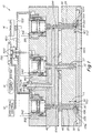
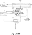
- FIG 1 shows a system 10 with a central nozzle 22 feeding molten material from an injection molding machine through a main inlet 18 to a distribution channel 19 of a manifold 40.
- the distribution channel 19 commonly feeds three separate nozzles 20, 22, 24 which all commonly feed into a common cavity 30 of a mold 42.
- One of the nozzles 22 is controlled by actuator 940 and arranged so as to feed into cavity 30 at an entrance point or gate that is disposed at about the center 32 of the cavity.
- a pair of lateral nozzles 20, 24 feed into the cavity 30 at gate locations that are distal 34, 36 to the center gate feed position 32.
- the injection cycle is a cascade process where injection is effected in a sequence from the center nozzle 22 first and at a later predetermined time from the lateral nozzles 20, 24.
- the injection cycle is started by first opening the pin 1040 of the center nozzle 22 and allowing the fluid material 100 (typically polymer or plastic material) to flow up to a position the cavity just before 100b the distally disposed entrance into the cavity 34, 36 of the gates of the lateral nozzles 24, 20 as shown in Fig. 1A .
- the fluid material 100 typically polymer or plastic material
- the gate of the center injection nozzle 22 and pin 1040 is typically left open only for so long as to allow the fluid material 100b to travel to a position just past 100p the positions 34, 36.
- the center gate 32 of the center nozzle 22 is typically closed by pin 1040 as shown in Figs. 1B, 1C , 1D and 1E .
- the lateral gates 34, 36 are then opened by upstream withdrawal of lateral nozzle pins 1041, 1042 as shown in Figs. 1B-1E .
- the rate of upstream withdrawal or travel velocity of lateral pins 1041, 1042 is controlled as described below.
- the center gate 32 and associated actuator 940 and valve pin 1040 can remain open at, during and subsequent to the times that the lateral gates 34, 36 are opened such that fluid material flows into cavity 30 through both the center gate 32 and one or both of the lateral gates 34, 36 simultaneously.
- the rate or velocity of upstream withdrawal of pins 1041, 1042 starting from the closed position is controlled via controller 16, Figs. 1 , 2 which controls the rate and direction of flow of hydraulic fluid from the drive system 700 to the actuators 940, 941, 942.
- controller 16 Figs. 1 , 2 which controls the rate and direction of flow of hydraulic fluid from the drive system 700 to the actuators 940, 941, 942.
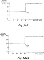
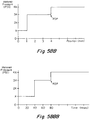
- a predetermined profile of metered drive fluid pressure versus position of the valve pin or actuator piston (examples of which are shown in Figs. 5AA , 5BB ) or metered drive fluid pressure versus elapsed time (examples of which are shown in Figs. 5AAA , 5BBB ) is input into the controller as the basis for controlling withdrawal of the valve pin(s) 1041 et al.
- the controller 16 receives a signal in real time from a pressure sensor 603 (or 605, 607) disposed in the drive fluid line communicating with the exit of the metering valve 600, the signal being indicative of the reduced drive fluid pressure in line 703 (or 705, 707).
- the controller 16 instructs the valve 600 to move to a degree of openness that causes the fluid pressure in the line to match the pressure of the predetermined profile at any given point in time or pin position along the pressure versus time profile (e.g. Fig. 5AAA or 5BBB ) or pressure versus position profile ( Figs. 5AA or 5BB .
- the pressure in the exit line of the metering valve 600 is proportional and corresponds to the velocity of withdrawal movement of the actuator 941 (940, 942) and associated valve pin 1041 (1040, 1042).
- a “controller,” as used herein, refers to electrical and electronic control apparati that comprise a single box or multiple boxes (typically interconnected and communicating with each other) that contain(s) all of the separate electronic processing, memory and electrical signal generating components that are necessary or desirable for carrying out and constructing the methods, functions and apparatuses described herein.
- Such electronic and electrical components include programs, microprocessors, computers, PID controllers, voltage regulators, current regulators, circuit boards, motors, batteries and instructions for controlling any variable element discussed herein such as length of time, degree of electrical signal output and the like.
- a component of a controller includes programs, controllers and the like that perform functions such as monitoring, alerting and initiating an injection molding cycle including a control device that is used as a standalone device for performing conventional functions such as signaling and instructing an individual injection valve or a series of interdependent valves to start an injection, namely move an actuator and associated valve pin from a gate closed to a gate open position.
- a control device that is used as a standalone device for performing conventional functions such as signaling and instructing an individual injection valve or a series of interdependent valves to start an injection, namely move an actuator and associated valve pin from a gate closed to a gate open position.
- actuators powered by an electric or electronic motor or drive source can alternatively be used as the actuator component.
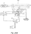
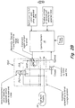
- a supply of hydraulic fluid 14 is fed first through a directional control valve 750 mechanism that switches the hydraulic fluid flow to the actuator cylinders in either of two directions: fluid out to withdraw the pin upstream, Fig. 2A , 2AA and fluid in to drive the pin downstream, Fig. 2AAA .
- a directional control valve 750 mechanism that switches the hydraulic fluid flow to the actuator cylinders in either of two directions: fluid out to withdraw the pin upstream, Fig. 2A , 2AA and fluid in to drive the pin downstream, Fig. 2AAA .
- the gate of a lateral valve 34, 36 is closed and the hydraulic system is in the directional configuration of Fig. 2AAA .
- the directional configuration of the directional valve 750 of the hydraulic system 700 is switched by controller 16 to the configuration of Fig. 2A or 2AA .
- the hydraulic system includes a flow restriction valve 600 that is controlled by controller 16 to vary the rate of flow of hydraulic fluid to the actuator 941, 951 to vary the rate of travel of the actuator 941/valve pin 1041 upstream according to a predetermined pressure profile (e.g. Figs. 5AA, 5AAA , 5BB, 5BBB ) or to drive the actuator 941/valve pin 1041 downstream.
- a predetermined pressure profile e.g. Figs. 5AA, 5AAA , 5BB, 5BBB
- the controller 16 and hydraulic system 700 can control the direction and rate of travel of the pistons of actuators 940 and 942 in a manner similar to the manner of control of actuator 941 via the connections shown in Fig. 1 .
- the user programs controller 16 via data inputs on a user interface to instruct the hydraulic system 700 via control of the degree of openness of the restriction valve 600 to drive pins 1041, 1042 at an upstream velocity of travel that is reduced relative to a maximum velocity that the hydraulic system 700 can drive the pins 1041, 1042 to travel.
- the reduced velocity at which the actuator 941 and associated valve pin 1041 are driven is determined by a predetermined profile of reduced drive fluid pressures that is followed by the controller 16 based on the metered pressure exiting valve 600 that is sensed by sensor 603 in line 703 and sent to the controller 16 during an injection cycle, the controller 16 controlling the degree of openness of valve 600 which in turn controls the degree of pressure exiting valve 600 in line 703.
- the controller 16 drives the actuator 941/valve pin 1041 at the profile of reduced pin withdrawal rate or velocity either until a position sensor such as 951, 952 detects that an actuator 941, 952 or an associated valve pin (or another component), has reached a certain position (e.g. as in Figs. 5AA , 5BB ) as sensed by the position sensor 951, 952 such as at the end point COP, COP2, Figs. 3B , 4B of a restricted flow path RP, RP2,
- the user can program controller 16 via to instruct the hydraulic system 700 to drive pins 1041, 1042 at the profile of reduced velocity of upstream travel for a predetermined amount of time.
- the reduced pin withdrawal rate or velocity is executed for a preselected amount of time that is less than the time of the entire injection cycle, the latter part of the injection cycle being executed with the pins 1041, 1042 being withdrawn at a higher velocity typically the highest velocity at which the hydraulic system is capable of driving the pins 1041, 1042.
- a typical amount of time over which the pins are instructed to withdraw at a reduced velocity is between about 0.25 and about 10 seconds, more typically between about 0.5 and about 5 seconds, the entire injection cycle time typically being between about 4 seconds and about 30 seconds, more typically between about 6 seconds and about 12 seconds.
- the periods of time over which the pins 1041, 1042 are withdrawn at reduced velocities are typically determined empirically by trial and error runs. One or more, typically multiple, trial injection cycle runs are carried out to make specimen parts from the mold.
- Each trial injection cycle run is carried out using a different period or periods of time at which the pins 1041, 1042 are withdrawn at one or more reduced velocities over the trial period(s) of time, and the quality of the parts produced from all such trial runs are compared to determine the optimum quality producing time(s) of reduced velocity pin withdrawals.
- the controller is programmed to carry out an injection cycle where the pin withdrawal velocities of pins 1041 are reduced for the predetermined amounts of time at the predetermined reduced withdrawal rates.
- Fig. 1 shows position sensors 950, 951, 952 for sensing the position of the actuator cylinders 941, 942, 952 and their associated valve pins (such as 1041, 1042, 1052) and feed such position information to controller 16 for monitoring purposes.
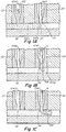
- fluid material 18 is injected from an injection machine into a manifold runner 19 and further downstream into the bores 44, 46 of the lateral nozzles 24, 22 and ultimately downstream through the gates 32, 34, 36.
- the pins 1041, 1042 are withdrawn upstream to a position where the tip end of the pins 1041 are in a fully upstream open position such as shown in Fig. 1D , the rate of flow of fluid material through the gates 34, 36 is at a maximum.
- a gap 1154, 1156 that restricts the velocity of fluid material flow is formed between the outer surfaces 1155 of the tip end of the pins 44, 46 and the inner surfaces 1254, 1256 of the gate areas of the nozzles 24, 20.
- the restricted flow gap 1154, 1156 remains small enough to restrict and reduce the rate of flow of fluid material 1153 through gates 34, 36 to a rate that is less than maximum flow velocity over a travel distance RP of the tip end of the pins 1041, 1042 going from closed to upstream as shown in Figs. 1 , 1B , 1C , 1E and 3B , 4B .
- the pins 1041 can be controllably withdrawn at one or more reduced velocities (less than maximum) for one or more periods of time over the entirety of the length of the path RP over which flow of mold material 1153 is restricted.
- the pins are withdrawn at a reduced velocity over more than about 50% of RP and most preferably over more than about 75% of the length RP.
- the pins 1041 can be withdrawn at a higher or maximum velocity at the end COP2 of a less than complete restricted mold material flow path RP2.
- the trace or visible lines that appear in the body of a part that is ultimately formed within the cavity of the mold on cooling above can be reduced or eliminated by reducing or controlling the velocity of the pin 1041, 1042 opening or upstream withdrawal from the gate closed position to a selected intermediate upstream gate open position that is preferably 75% or more of the length of RP.
- RP can be about 1-8 mm in length and more typically about 2-6 mm and even more typically 2-4 mm in length.
- a control system or controller 16 is preprogrammed to control the sequence and the rates of valve pin 1040, 1041, 1042 opening and closing.
- the controller 16 controls the rate of travel, namely velocity of upstream travel, of a valve pin 1041, 1042 from its gate closed position for at least the predetermined amount of time that is selected to withdraw the pin at the selected reduced velocity rate.
- the velocity of withdrawal of the valve pins 1041, 1042 is determined by regulation of the flow of hydraulic drive fluid that is pumped from a supply 14 to the actuators 941, 942 through flow restrictor valve 600, Figs. 1 , 2 , 2A , 2B .
- the flow restrictor valve 600 is completely open, namely 100% open, allowing maximum flow of the pressurized hydraulic fluid to the actuator cylinders, the valve pins 1041, 1042 are driven at a maximum upstream travel velocity.
- the degree of openness of the flow restrictor valve 600 is adjusted in response to sensing with sensor 603 of the drive fluid pressure that exits restrictor valve 600.
- the controller automatically adjusts the degree of openness of flow restrictor valve 600 to less than 100% open to cause the reduced pressure in line 703 to match and follow the predetermined profile of pressure shown for example in Figs. 5AA, 5AAA , 5BB, 5BBB which in turn adjusts rate and volume flow of pressurized hydraulic fluid to the actuator cylinders which in turn adjusts the velocity of upstream travel of the pins 1041, 1042 according to the predetermined exit pressure in line 703 for either a selected period of time as in Figs.
- the controller 16 instructs the metering valve to open to a greater degree of openness to drive the actuator 941 /pin 1041 at a higher velocity typically to the highest degree of openness of the valve 600 and thus the highest possible velocity.
- the actuator/valve pin travels the predetermined length of the reduced velocity path RP, RP2, at the end of which the position sensor signals the controller 16 whereby the controller 16 determines that the end COP, COP2 has been reached and the valve 600 is opened to a higher velocity, typically to its 100% open position to allow the actuator pistons and the valve pins 1041, 1042 to be driven at maximum upstream velocity FOV in order to reduce the cycle time of the injection cycle.
- the valve 600 typically comprises a restrictor valve that is controllably positionable anywhere between completely closed (0% open) and completely open (100% open). Adjustment of the position of the restrictor valve 600 is typically accomplished via a source of electrical power that controllably drives an electromechanical mechanism that causes the valve to rotate such as a rotating spool that reacts to a magnetic or electromagnetic field created by the electrical signal output of the controller 16, namely an output of electrical energy, electrical power, voltage, current or amperage the degree or amount of which can be readily and controllably varied by conventional electrical output devices.
- the electro-mechanism is controllably drivable to cause the valve 600 to open or close to a degree of openness that is proportional to the amount or degree of electrical energy that is input to drive the electro-mechanism.
- the velocity of upstream withdrawal travel of the pins 1041, 1042 are in turn proportional to the degree of openness of the valve 600.
- the rate of upstream travel of the pins 1041, 1042 is proportional to the amount or degree of electrical energy that is input to the electro-mechanism drives valves 600.
- the electro-mechanism that is selected for driving the valve 600 establishes in the first instance the maximum amount of electrical energy or power (such as voltage or current) that is required to open the valve to its 100% open position.
- the user implements a reduced upstream velocity of the pins 1041, 1042 over a given upstream length of travel or over a given amount of time by inputting to the controller 16 a profile of reduced exit fluid pressures that are implemented by adjusting the electrical drive mechanism that operates metering valve 600 to less than 100% of the maximum amount of electrical energy or power input (voltage or current) needed to open the valve 600 to 100% open at which setting maximum drive fluid pressure and, a fortiori, maximum actuator/pin velocity occurs.
- the user can implement reduced actuator/pin withdrawal velocity profiles by inputting reduced exit pressure profiles (or other data corresponding thereto) versus actuator/pin position into the controller 16.
- Exit pressure is the pressure of the valve drive fluid that exits the metering valve 600 during the upstream withdrawal portion of the injection cycle.
- the exit pressure would be the pressure in one of lines 703, 705 or 707 as sensed by a respective one of sensors 603, 605, 607.
- the user can implement reduced actuator/pin withdrawal velocity profiles by inputting to the controller 16 reduced exit pressure profiles or other data corresponding.thereto) versus time of withdrawal beginning from the time at which the gate is closed.
- the user can also preselect the length of the path of travel RP, RP2 of the valve pin or other end of reduced velocity position of the valve pin or other component over the course of travel of which the material flow through the gate is restricted and input such selections into the controller 16.
- the user can preselect the length of time during which the gate is restricted by a valve pin travelling over a restricted path length RP, RP2 and input such a selection into the controller 16.
- the controller 16 includes conventional programming or circuitry that receives and executes the user inputs.
- the controller may include programming or circuitry that enables the user to input as a variable a selected pin velocity rather than a percentage of electrical output, the programming of the controller 16 automatically converting the inputs by the user to appropriate instructions for reduced energy input to the electro-mechanism that drives the valve 600.
- the user selects a profile of metered exit drive fluid pressures that corresponds to reduced pin withdrawal velocities that are less than about 90% of the maximum velocity (namely the velocity when the valve 600 is fully open), more typically less than about 75% of the maximum velocity and even more typically less than about 50% of the maximum velocity at which the pins 1041, 1042 are drivable by the hydraulic system.
- the actual maximum velocity at which the actuators 941, 942 and their associated pins 1041, 1042 are driven is predetermined by selection of the size and configuration of the actuators 941, 942, the size and configuration of the restriction valve 600 and the degree of pressurization and type of hydraulic drive fluid selected for use by the user.
- the maximum drive rate of the hydraulic system is predetermined by the manufacturer and the user of the system and is typically selected according to the application, size and nature of the mold and the injection molded part to be fabricated.
- one or more profiles of reduced pin withdrawal velocity can be selected and the pin driven by restricted hydraulic fluid flow between the gate closed (X and Y axis zero position) and the final intermediate upstream open gate position (4mm for example in the Fig. 5A example, 5mm in the Fig. 5B example) at which point the controller 16 in response to position sensing instructs the drive system to drive pin 1041, 1042 to travel upstream at a higher, typically maximum, upstream travel velocity (as shown, 100 mm/sec in the Figs. 5A-5D examples).
- the controller 16 in response to position sensing instructs the drive system to drive pin 1041, 1042 to travel upstream at a higher, typically maximum, upstream travel velocity (as shown, 100 mm/sec in the Figs. 5A-5D examples).
- the profile of reduced pin velocity is selected as being about 50, 25 and 75 mm/sec over the initial reduced velocity path length.
- the velocity of the pin may or may not be precisely known, the Y velocity axis of Figs. 5A, 5B corresponding to the drive fluid pressure profile of Figs. 5AA, 5AAA , 5BB, 5BBB , the degree of precision in control over which depends and may vary slightly with the degree of precision in control over the opening of the flow restriction valve 600, 100 mm/sec corresponding to the valve 600 being completely 100% open (and pin being driven at maximum velocity); and 50 mm/sec corresponding to 50% electrical energy input to the electromechanism that drives the restriction valve 600 to one-half of its maximum 100% degree of openness.
- the path length RP over which the valve pin 1041, 1042 travels at the reduced 50 mm/sec velocity is 4mm.
- the controller 16 instructs the electro-mechanism that drives the valve 600 (typically a magnetic or electromagnetic field driven device such as a spool) to open the restrictor valve 600 to full 100% open at which time the pin (and its associated actuator piston) are driven by the hydraulic system at the maximum travel rate 100 mm/sec for the predetermined, given pressurized hydraulic system.
- the valve 600 typically a magnetic or electromagnetic field driven device such as a spool
- Figs. 5B - 5D illustrate a variety of alternative profiles for driving the pin 1041, 1042 at reduced velocities for various durations of time.
- the pin is driven for .02 seconds at 25 mm/sec, then for .06 seconds at 75 mm/sec and then allowed to go to full valve open velocity shown as 100 mm/sec.
- Full valve open or maximum velocity is typically determined by the nature of hydraulic (or pneumatic) valve or motor drive system that drives the valve pin.
- the maximum velocity that the system is capable of implementing is determined by the nature, design and size of the pumps, the fluid delivery channels, the actuator, the drive fluid (liquid or gas), the restrictor valves and the like.
- the valve 600 can be instructed to assume the full open position essentially instantaneously or alternatively can be instructed to take a more gradual approach up, between .08 and .12 seconds, to the maximum valve openness as shown in Fig. 5D .
- the controller 16 instructs the valve pin 1041, 1042 to travel continuously upstream rather than follow a drive fluid pressure profile where the pin might travel in a downstream direction during the course of the injection cycle.
- the actuator, valve pin, valves and fluid drive system are adapted to move the valve pin between a gate closed position and a maximum upstream travel position that defines an end of stroke position for the actuator and the valve pin.
- valve pin is moved at the maximum velocity at one or more times or positions over the course of upstream travel of the valve pin past the upstream gate open position.
- a pneumatic or gas driven system can be used and implemented in the same manner as described above for a hydraulic system.
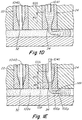
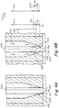
- valve pin and the gate are configured or adapted to cooperate with each other to restrict and vary the rate of flow of fluid material 1153, Figs. 3A-3B , 4A-4B over the course of travel of the tip end of the valve pin through the restricted velocity path RP.
- the radial tip end surface 1155 of the end 1142 of pin 1041, 1042 is conical or tapered and the surface of the gate 1254 with which pin surface 1155 is intended to mate to close the gate 34 is complementary in conical or taper configuration.
- Figs. 3A, 3B the radial tip end surface 1155 of the end 1142 of pin 1041, 1042 is conical or tapered and the surface of the gate 1254 with which pin surface 1155 is intended to mate to close the gate 34 is complementary in conical or taper configuration.
- the radial surface 1155 of the tip end 1142 of the pin 1041, 1042 can be cylindrical in configuration and the gate can have a complementary cylindrical surface 1254 with which the tip end surface 1155 mates to close the gate 34 when the pin 1041 is in the downstream gate closed position.
- the outside radial surface 1155 of the tip end 1142 of the pin 1041 creates restricted a restricted flow channel 1154 over the length of travel of the tip end 1142 through and along restricted flow path RP that restricts or reduces the volume or rate of flow of fluid material 1153 relative to the rate of flow when the pin 1041, 1042 is at a full gate open position, namely when the tip end 1142 of the pin 1041 has travelled to or beyond the length of the restricted flow path RP (which is, for example the 4 mm upstream travel position of Figs 5A-5C ).
- the rate of material fluid flow 1153 through restriction gap 1154 through the gate 34 into the cavity 30 continues to increase from 0 at gate closed GC position to a maximum flow rate when the tip end 1142 of the pin reaches a position FOP (full open position), Figs. 5A-5D , where the pin is no longer restricting flow of injection mold material through the gate.
- the pin 1041 is immediately driven by the hydraulic system at maximum velocity FOV (full open velocity) typically such that the restriction valve 600 is opened to full 100% open.
- FOV full open velocity
- the fluid flow 1153 can still be restricted to less than maximum flow when the pin has reached the changeover position COP2 where the pin 1041 is driven at a higher, typically maximum, upstream velocity FOV.
- the pin 1041 can be driven at a reduced velocity over a shorter path RP2 that is less than the entire length of the restricted mold material flow path RP and switched over at the end COP2 of the shorter restricted path RP2 to a higher or maximum velocity FOV.
- the upstream FOP position is about 4mm and 5mm respectively upstream from the gate closed position.
- Other alternative upstream FOP positions are shown in Figs. 5C, 5D .
- the pin 1041 can be driven and instructed to be driven at reduced or less than maximum velocity over a longer path length RP3 having an upstream portion UR where the flow of injection fluid mold material is not restricted but flows at a maximum rate through the gate 34 for the given injection mold system.
- the velocity or drive rate of the pin 1041 is not changed over until the tip end of the pin 1041 or actuator 941 has reached the changeover position COP3.
- a position sensor senses either that the valve pin 1041 or an associated component has travelled the path length RP3 or reached the end COP3 of the selected path length and the controller receives and processes such information and instructs the drive system to drive the pin 1041 at a higher, typically maximum velocity upstream.
- the pin 1041 can be driven at a less than maximum velocity throughout the entirety of the travel path of the pin during an injection cycle from the gate closed position GC up to the end-of-stroke EOS position, the controller 16 being programmed to instruct the drive system for the actuator to be driven at one reduced velocity for an initial path length or period of time and at another less than maximum velocity subsequent to the intial reduced velocity path or period of time for the remainder of the injection cycle whereby the actuator/valve pin travels at a less than maximum velocity for an entire closed GC to fully open EOS cycle.
- FOV is 100 mm/sec.
- the restriction valve 600 is opened to full 100% open velocity FOV position such that the pins 1041, 1042 are driven at the maximum velocity or rate of travel that the hydraulic system is capable of driving the actuators 941, 942.
- the pins 1041, 1042 can be driven at a preselected FOV velocity that is less than the maximum velocity at which the pin is capable of being driven when the restriction valve 600 is fully open but is still greater than the selected reduced velocities that the pin is driven over the course of the RP, RP2 path to the COP, COP2 position.
- the pins 1041, 1042 are typically driven further upstream past the COP, COP2 position to a maximum end-of-stroke EOS position.
- the upstream COP, COP2 position is downstream of the maximum upstream end-of-stroke EOS open position of the tip end 1142 of the pin.
- the length of the path RP or RP2 is typically between about 2 and about 8 mm, more typically between about 2 and about 6 mm and most typically between about 2 and about 4 mm.
- the maximum upstream (end of stroke) open position EOS of the pin 1041, 1042 ranges from about 8 mm to about 18 inches upstream from the closed gate position GC.
- the controller 16 includes a processor, memory, user interface and circuitry and/or instructions that receive and execute the user inputs of percentage of maximum valve open or percentage of maximum voltage or current input to the motor drive for opening and closing the restriction valve, time duration for driving the valve pin at the selected valve openings and reduced velocities.
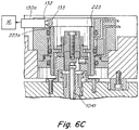
- FIGs. 6A-6D show various examples of position sensors 100, 114, 227, 132 the mounting and operation of which are described in U.S. Patent Publication no. 20090061034 the disclosure of which is incorporated herein by reference.
- the position sensor of Fig. 6A and 6B for example can track and signal the position of the piston of the actuator piston 223 continuously along its entire path of travel from which data pin velocity can be continuously calculated over the length of RP, RP2, RP3 via spring loaded follower 102 that is in constant engagement with flange 104 during the course of travel of piston 223.
- Mechanism 100 constantly sends signals to controller 16 in real time to report the position of pin 1041 and its associated actuator.
- FIG. 6C , 6D show alternative embodiments using position switches that detect position at specific individual positions of the actuator and its associated valve pin 1041.
- the Fig. 6C embodiment uses a single trip position switch 130a with trip mechanism 133 that physically engages with the piston surface 223a when the piston 223 reaches the position of the trip mechanism 133.
- the Fig. 6D embodiment shows the use of two separate position switches 130a, 130aa having sequentially spaced trips 133aa and 133aaa that report the difference in time or distance between each trip engaging surface 223a of the piston, the data from which can be used by controller 16 to calculate velocity of the actuator based on the time of travel of the actuator from tripping one switch 130a and then tripping the next 130aa.
- the position switch can signal the controller 16 when the valve pin 1041, 1042 has travelled to one or more selected intermediate upstream gate open positions between GC and RP, RP2 or RP3 so that the velocity of the pin can be adjusted to the selected or predetermined velocities determined by the user.
- position sensor mechanisms can be used such as optical sensors, sensors that mechanically or electronically detect the movement of the valve pin or actuator or the movement of another component of the apparatus that corresponds to movement of the actuator or valve pin.
- control over the withdrawal (upstream) velocity of actuator or pin movement is accomplished by controlling the degree of fluid pressure that exits the metering valve which in turn is controlled by controlling the degree of openness of the fluid restriction valve 600.
- a profile of exit fluid pressures versus time or pin position is determined in advance and input to the controller which includes a program and instructions that automatically adjust the position of valve 600 based on the real time pressure signal received from sensor 603 (or 605 or 607) to adjust the exit pressure of the drive fluid in line 703 (or 705 or 707) which in turn adjusts the rate or velocity of upstream movement of the actuator 941/valve pin 1041 (and/or actuators 1040, 1042 and valve pins 940, 942).
Landscapes
- Engineering & Computer Science (AREA)
- Manufacturing & Machinery (AREA)
- Mechanical Engineering (AREA)
- Moulds For Moulding Plastics Or The Like (AREA)
- Injection Moulding Of Plastics Or The Like (AREA)
Claims (15)
- Appareil destiné à commander la vitesse d'écoulement d'un matériau de moulage fluide provenant d'une machine de moulage par injection vers une cavité de moule (30), l'appareil comprenant :un collecteur (40) recevant le matériau de moulage fluide injecté, lequel collecteur (40) présente un canal de distribution qui délivre le matériau fluide injecté à une première entrée (34) conduisant à la cavité de moule (30) ;un actionneur (940, 941, 942) relié à une tige de soupape (1040, 1041, 1042) présentant une extrémité de pointe (1142), pouvant être entraînée le long d'un chemin d'entraînement qui s'étend entre une première position où l'extrémité de pointe (1142) de la tige de soupape (1040, 1041, 1042) obstrue la première entrée (34) pour empêcher le matériau fluide d'injection de s'écouler dans la cavité (30), une deuxième position en amont de la première position dans laquelle l'extrémité de pointe (1142) de la tige de soupape (1040, 1041, 1042) restreint l'écoulement du fluide d'injection à travers la première entrée (34) le long d'au moins une partie de la longueur du chemin d'entraînement s'étendant entre la première position et la deuxième position, et une troisième position en amont de la deuxième position où le matériau fluide d'injection s'écoule librement à travers la première entrée (34), sans restriction de l'extrémité de pointe (1142) de la tige,l'actionneur (940, 941, 942) et la tige de soupape (1040, 1041, 1042) étant entraînés en translation à une vitesse de déplacement pouvant être commandée par un système de soupape réglable de manière commandée entre une position de départ, une pluralité de positions de vitesse d'entraînement intermédiaires et une position de vitesse d'entraînement élevée, l'actionneur (940, 941, 942) étant entraîné en amont à une pluralité correspondante de vitesses de déplacement intermédiaires quand le système de soupape est dans une ou plusieurs de la pluralité de positions de vitesse d'entraînement intermédiaires et à une vitesse de déplacement plus élevée que la pluralité de vitesses de déplacement intermédiaires quand le système de soupape est dans la position de vitesse d'entraînement élevée ;un capteur de position (950, 951, 952),un capteur de pression (603, 605, 607),un dispositif de commande (16),le capteur de position (950, 951, 952) détectant la position de la tige de soupape (1040, 1041, 1042) et envoyant un signal qui indique la position de la tige au dispositif de commande (16) ;le capteur de pression (603, 605, 607) détectant une pression dosée d'un fluide d'entraînement s'écoulant d'une sortie du système de soupape, la pression dosée correspondant à une position de vitesse d'entraînement du système de soupape, le capteur de pression (603, 605, 607) envoyant un signal qui indique la pression dosée au dispositif de commande (16) ;le dispositif de commande (16) donnant au système de soupape l'ordre d'entraîner l'actionneur (940, 941, 942) et la tige de soupape (1040, 1041, 1042) de façon continue en amont de la position de départ vers la deuxième position et la troisième position ;le dispositif de commande (16) comprenant des instructions qui donnent au système de soupape l'ordre de se déplacer selon un profil prédéterminé de pressions dosées en fonction des positions de tige depuis la position de départ jusqu'à des positions de vitesse d'entraînement intermédiaires sélectionnées de la pluralité de positions de vitesse d'entraînement intermédiaires qui correspondent au profil des pressions dosées et ensuite de se déplacer des positions de vitesse d'entraînement intermédiaires sélectionnées de la pluralité de positions de vitesse d'entraînement intermédiaires jusqu'à la position de vitesse d'entraînement élevée à la réception par le dispositif de commande (16) d'un signal du capteur de position (950, 951, 952) qui indique que la tige de soupape (1040, 1041, 1042) a atteint la deuxième position.
- Appareil selon la revendication 1, comprenant en outre un dispositif générateur de signaux électriques relié au système de soupape pour entraîner de manière commandée le système de soupape à des degrés d'ouverture sélectionnés, le dispositif générateur de signaux électriques générant un signal électrique de degré de sortie variable de manière commandée, le système de soupape étant réglable à un degré d'ouverture qui est approximativement proportionnel au degré de sortie du signal électrique.
- Appareil selon la revendication 2, dans lequel le dispositif générateur de signaux électriques est relié au dispositif de commande (16), le dispositif de commande (16) donnant au dispositif générateur de signaux électriques l'ordre de générer des signaux électriques de degrés de sortie variables qui correspondent à un degré d'ouverture des une ou plusieurs positions de vitesse d'entraînement intermédiaires et de la troisième position de vitesse d'entraînement du système de soupape.
- Appareil selon la revendication 1, dans lequel la longueur du chemin d'entraînement entre la première position et la deuxième position est comprise entre environ 1 mm et environ 5 mm.
- Appareil selon la revendication 1, dans lequel la tige de soupape (1040, 1041, 1042) et l'actionneur (940, 941, 942) sont entraînés à une vitesse maximale de déplacement en amont à laquelle le système de soupape est capable d'entraîner l'actionneur (940, 941, 942) quand le système de soupape est dans la position de vitesse d'entraînement élevée.
- Appareil selon la revendication 1, dans lequel les positions du système de soupape ont chacune un degré d'ouverture différent, l'actionneur (940, 941, 942) et la tige de soupape (1040, 1041, 1042) étant entraînés à une vitesse qui est proportionnelle au degré d'ouverture des positions du système de soupape, le dispositif de commande (16) donnant l'ordre de générer un signal électrique qui règle le système de soupape à un degré d'ouverture qui est proportionnel à un degré de sortie du signal électrique, le dispositif de commande (16) étant programmable pour donner l'ordre de générer un ou plusieurs premiers signaux électriques ayant un ou plusieurs premiers degrés de sortie sélectionnés correspondants qui déplacent le système de soupape dans les une ou plusieurs positions de vitesse d'entraînement intermédiaires pour entraîner l'actionneur (940, 941, 942) à une ou plusieurs premières vitesses dans la direction de l'amont, le dispositif de commande (16) étant programmé pour donner l'ordre de générer un deuxième signal électrique quand le dispositif de commande (16) reçoit un signal du capteur de position (950, 951, 952) indiquant que l'extrémité de pointe (1142) de la tige de soupape (1040, 1041, 1042) a atteint la deuxième position, le deuxième signal électrique ayant un deuxième degré de sortie sélectionné qui déplace le système de soupape dans la position de vitesse d'entraînement élevée qui entraîne l'actionneur (940, 941, 942) à une deuxième vitesse qui est plus élevée que les une ou plusieurs premières vitesses.
- Procédé pour effectuer un cycle de moulage par injection dans un appareil de moulage par injection comprenant :un collecteur (40) qui reçoit un matériau de moulage fluide injecté, lequel collecteur (40) présente un canal de distribution qui délivre le matériau de moulage fluide d'injection sous une pression d'injection à une première entrée (34) d'une cavité de moule (30),un actionneur (940, 941, 942) relié en entraînement à une tige de soupape (1040, 1041, 1042) présentant une extrémité de pointe (1142) pouvant être entraînée le long d'un chemin d'entraînement qui s'étend entre une première position où l'extrémité de pointe (1142) de la tige de soupape (1040, 1041, 1042) obstrue l'entrée (34) pour empêcher le matériau fluide d'injection de s'écouler dans la cavité (30), une deuxième position en amont de la première position dans laquelle l'extrémité de pointe (1142) de la tige de soupape (1040, 1041, 1042) restreint l'écoulement du fluide d'injection le long d'au moins une partie de la longueur du chemin d'entraînement s'étendant entre la première position et la deuxième position, et une troisième position en amont de la deuxième position où le matériau fluide d'injection s'écoule librement, sans restriction de l'extrémité de pointe (1142) de la tige à travers la première entrée (34),l'actionneur (940, 941, 942) étant entraîné par un système de soupape qui est réglable de manière commandée entre une position de départ, une pluralité de positions de vitesse d'entraînement intermédiaires et une position de vitesse d'entraînement élevée, l'actionneur (940, 941, 942) étant entraîné en amont à une pluralité de vitesses de déplacement intermédiaires correspondantes quand le système de soupape est dans une de la pluralité de positions de vitesse d'entraînement intermédiaires et à une vitesse de déplacement plus élevée que la pluralité de vitesses de déplacement intermédiaires quand le système de soupape est dans la position de vitesse d'entraînement élevée,le système de soupape comprenant une ligne d'écoulement de fluide conduisant un fluide d'entraînement par une sortie du système de soupape sous une pression dosée,le procédé consistant à :sélectionner la longueur de déplacement entre la première position et la deuxième position en détectant la pression dosée du fluide d'entraînement dans la ligne d'écoulement de fluide,détecter la position de la tige de soupape (1040, 1041, 1042),sélectionner un profil de pressions dosées en fonction de la position de la tige de soupape (1040, 1041, 1042), le profil de pressions dosées correspondant à des positions de vitesse d'entraînement intermédiaires sélectionnées de la pluralité de positions de vitesse d'entraînement intermédiaires,commencer un cycle d'injection avec l'extrémité de pointe (1142) de la tige de soupape (1040, 1041, 1042) dans la première position et le système de soupape dans la position de départ,régler le système de soupape en fonction du profil sélectionné pour qu'il fonctionne aux positions de vitesse d'entraînement intermédiaires sélectionnées de la pluralité de positions de vitesse d'entraînement intermédiaires pour entraîner l'extrémité de pointe (1142) de la tige de soupape (1040, 1041, 1042) de façon continue en amont de la première position vers la deuxième position,détecter la position de la tige de soupape (1040, 1041, 1042) pour déterminer quand l'extrémité de pointe (1142) de la tige de soupape (1040, 1041, 1042) a atteint la deuxième position,régler le système de soupape pour qu'il fonctionne à la position de vitesse d'entraînement élevée pour entraîner l'extrémité de pointe (1142) de la tige de soupape (1040, 1041, 1042) de façon continue en amont à la vitesse de déplacement plus élevée quand il a été déterminé, dans l'étape de détection, que l'extrémité de pointe (1142) de la tige de soupape (1040, 1041, 1042) a atteint la deuxième position.
- Procédé selon la revendication 7, selon lequel l'étape consistant à régler le système de soupape pour qu'il fonctionne aux une ou plusieurs positions de vitesse d'entraînement intermédiaires sélectionnées commence après que le matériau de moulage fluide d'injection a été précédemment injecté dans la cavité (30) à travers une autre entrée (34) et que le matériau de moulage fluide s'est déplacé à travers la cavité (30) au-delà de la première entrée (34).
- Procédé selon la revendication 7, selon lequel l'étape consistant à régler le système de soupape pour qu'il fonctionne aux une ou plusieurs positions de vitesse d'entraînement intermédiaires sélectionnées consiste à régler le système de soupape pour qu'il fonctionne à une seule position de vitesse d'entraînement intermédiaire.
- Procédé selon la revendication 12, selon lequel la position de vitesse d'entraînement élevée du système de soupape entraîne l'actionneur (940, 941, 942) à une vitesse de déplacement qui est la vitesse maximale à laquelle le système de soupape est capable d'entraîner l'actionneur (940, 941, 942).
- Procédé selon la revendication 7, selon lequel le système de soupape est relié à un dispositif générateur de signaux électriques permettant de générer un signal électrique de degré variable de manière commandée, le système de soupape étant réglable en position pour augmenter l'écoulement d'un fluide d'entraînement à un degré qui est proportionnel au degré du signal électrique fourni par le dispositif générateur de signaux électriques au système de soupape, les étapes consistant à régler le système de soupape consistant à faire fonctionner le dispositif générateur de signaux électriques pour qu'il règle les positions du système de soupape.
- Procédé selon la revendication 7, selon lequel chacune des positions de départ, de vitesse d'entraînement intermédiaire et de vitesse d'entraînement élevée du système de soupape a un degré d'ouverture différent, le fluide d'entraînement du système de soupape entraînant l'actionneur (940, 941, 942) et la tige de soupape (1040, 1041, 1042) à une vitesse qui est approximativement proportionnelle au degré d'ouverture des positions du système de soupape, les une ou plusieurs positions de vitesse d'entraînement intermédiaires ayant un degré d'ouverture qui est inférieur au degré d'ouverture de la position de vitesse d'entraînement élevée.
- Procédé selon la revendication 7, selon lequel la longueur de déplacement entre la première position et la deuxième position le long du chemin d'entraînement est sélectionnée pour être comprise entre environ 1 mm et environ 5 mm.
- Procédé selon la revendication 7, selon lequel l'étape de détection consiste à détecter la position de la tige de soupape (1040, 1041, 1042) avec un capteur de position (950, 951, 952) qui envoie automatiquement un ou plusieurs signaux qui indiquent la position de l'extrémité de pointe (1142) de la tige de soupape (1040, 1041, 1042) à un mécanisme de commande qui règle automatiquement les positions du système de soupape en réponse à la réception des un ou plusieurs signaux du capteur de position (950, 951, 952).
- Procédé selon la revendication 14, selon lequel le mécanisme de commande comprend un dispositif générateur de signaux électriques permettant de générer un signal électrique de degré variable de manière commandée, le système de soupape étant réglable en position à un degré d'ouverture qui est approximativement proportionnel au degré du signal électrique fourni par le dispositif générateur de signaux électriques au système de soupape, les étapes consistant à régler le système de soupape consistant à faire fonctionner le dispositif générateur de signaux électriques pour qu'il règle de manière commandée le degré du signal électrique fourni au système de soupape.
Applications Claiming Priority (6)
| Application Number | Priority Date | Filing Date | Title |
|---|---|---|---|
| US201261730296P | 2012-11-27 | 2012-11-27 | |
| US201261736878P | 2012-12-13 | 2012-12-13 | |
| US201361770781P | 2013-02-28 | 2013-02-28 | |
| US201361802878P | 2013-03-18 | 2013-03-18 | |
| US201361838620P | 2013-06-24 | 2013-06-24 | |
| PCT/US2013/071667 WO2014085321A1 (fr) | 2012-11-27 | 2013-11-25 | Appareil et procédé de régulation d'écoulement pour moulage par injection |
Publications (2)
| Publication Number | Publication Date |
|---|---|
| EP2925503A1 EP2925503A1 (fr) | 2015-10-07 |
| EP2925503B1 true EP2925503B1 (fr) | 2017-01-25 |
Family
ID=49876981
Family Applications (1)
| Application Number | Title | Priority Date | Filing Date |
|---|---|---|---|
| EP13811661.1A Not-in-force EP2925503B1 (fr) | 2012-11-27 | 2013-11-25 | Appareil et procédé de régulation d'écoulement pour moulage par injection |
Country Status (3)
| Country | Link |
|---|---|
| EP (1) | EP2925503B1 (fr) |
| CN (1) | CN105121120B (fr) |
| WO (1) | WO2014085321A1 (fr) |
Families Citing this family (11)
| Publication number | Priority date | Publication date | Assignee | Title |
|---|---|---|---|---|
| AT515780B1 (de) | 2014-06-16 | 2015-12-15 | Engel Austria Gmbh | Verfahren zum Überwachen der Bewegung einer Kolben-Zylinder-Einheit |
| CN105714296B (zh) * | 2014-12-03 | 2018-06-05 | 北大方正集团有限公司 | 蚀刻介质的流量调节装置和蚀刻介质的流量调节方法 |
| US10543629B2 (en) | 2014-12-11 | 2020-01-28 | Inglass S.P.A. | Method and apparatus for injection molding of plastic materials |
| AT517390A1 (de) | 2015-07-03 | 2017-01-15 | Sonderhoff Engineering Gmbh | Dosiervorrichtung für flüssigen Kunststoff |
| CN105856524B (zh) * | 2016-05-13 | 2018-05-25 | 芜湖虹飞机械有限公司 | 一种流速自动修正型模具 |
| CN105946183A (zh) * | 2016-06-08 | 2016-09-21 | 上海文业扬实业有限公司 | 一种汽车内饰用塑料模具 |
| WO2019066776A1 (fr) * | 2017-09-26 | 2019-04-04 | Synventive Molding Solutions, Inc. | Appareil et procédé de régulation de débit de moulage par injection |
| EP3807069B1 (fr) * | 2018-08-17 | 2023-04-19 | Synventive Molding Solutions, Inc. | Canal d'écoulement de moulage par injection à écoulement traversant interrompu |
| CN109501185A (zh) * | 2018-11-27 | 2019-03-22 | 湖北工业大学 | 注塑成型工艺在线监测方法 |
| US11718005B2 (en) * | 2019-06-18 | 2023-08-08 | Incoe Corporation | Flow control of an injection molding system |
| CN111361098B (zh) * | 2020-03-16 | 2022-02-01 | 李金国 | 自扰流注塑模具浇注系统 |
Citations (2)
| Publication number | Priority date | Publication date | Assignee | Title |
|---|---|---|---|---|
| US6632079B1 (en) * | 1998-04-21 | 2003-10-14 | Synventive Molding Solutions, Inc. | Dynamic feed control system |
| WO2012074879A1 (fr) * | 2010-11-23 | 2012-06-07 | Synventive Molding Solutions, Inc. | Appareil et procédé de régulation de débit pour moulage par injection |
Family Cites Families (2)
| Publication number | Priority date | Publication date | Assignee | Title |
|---|---|---|---|---|
| US6464909B1 (en) * | 1998-04-21 | 2002-10-15 | Synventive Molding Solutions, Inc. | Manifold system having flow control |
| US6589039B1 (en) * | 1998-04-21 | 2003-07-08 | Synventive Molding Solutions, Inc. | Controlled injection using manifold having multiple feed channels |
-
2013
- 2013-11-25 WO PCT/US2013/071667 patent/WO2014085321A1/fr active Application Filing
- 2013-11-25 EP EP13811661.1A patent/EP2925503B1/fr not_active Not-in-force
- 2013-11-25 CN CN201380069040.5A patent/CN105121120B/zh active Active
Patent Citations (2)
| Publication number | Priority date | Publication date | Assignee | Title |
|---|---|---|---|---|
| US6632079B1 (en) * | 1998-04-21 | 2003-10-14 | Synventive Molding Solutions, Inc. | Dynamic feed control system |
| WO2012074879A1 (fr) * | 2010-11-23 | 2012-06-07 | Synventive Molding Solutions, Inc. | Appareil et procédé de régulation de débit pour moulage par injection |
Also Published As
| Publication number | Publication date |
|---|---|
| EP2925503A1 (fr) | 2015-10-07 |
| CN105121120A (zh) | 2015-12-02 |
| CN105121120B (zh) | 2017-09-26 |
| WO2014085321A1 (fr) | 2014-06-05 |
Similar Documents
| Publication | Publication Date | Title |
|---|---|---|
| US11148335B2 (en) | Injection molding flow control apparatus and method | |
| EP2925503B1 (fr) | Appareil et procédé de régulation d'écoulement pour moulage par injection | |
| US9738024B2 (en) | Downstream pin velocity controlled injection molding apparatus and method | |
| EP2888091B1 (fr) | Appareil et procédé de commande d'écoulement de moulage par injection | |
| US9682507B2 (en) | Injection molding flow control apparatus and method | |
| EP2931491B1 (fr) | Appareil et procédé de moulage par injection commandés par une vitesse de broche entraînés de façon pneumatique | |
| US20180015652A1 (en) | Injection flow control apparatus and method | |
| WO2019066776A1 (fr) | Appareil et procédé de régulation de débit de moulage par injection |
Legal Events
| Date | Code | Title | Description |
|---|---|---|---|
| PUAI | Public reference made under article 153(3) epc to a published international application that has entered the european phase |
Free format text: ORIGINAL CODE: 0009012 |
|
| 17P | Request for examination filed |
Effective date: 20150611 |
|
| AK | Designated contracting states |
Kind code of ref document: A1 Designated state(s): AL AT BE BG CH CY CZ DE DK EE ES FI FR GB GR HR HU IE IS IT LI LT LU LV MC MK MT NL NO PL PT RO RS SE SI SK SM TR |
|
| AX | Request for extension of the european patent |
Extension state: BA ME |
|
| DAX | Request for extension of the european patent (deleted) | ||
| 17Q | First examination report despatched |
Effective date: 20160419 |
|
| REG | Reference to a national code |
Ref country code: DE Ref legal event code: R079 Ref document number: 602013016833 Country of ref document: DE Free format text: PREVIOUS MAIN CLASS: B29C0045280000 Ipc: B29C0045000000 |
|
| GRAP | Despatch of communication of intention to grant a patent |
Free format text: ORIGINAL CODE: EPIDOSNIGR1 |
|
| RIC1 | Information provided on ipc code assigned before grant |
Ipc: B29C 45/82 20060101ALI20160704BHEP Ipc: B29C 45/76 20060101ALI20160704BHEP Ipc: B29C 45/00 20060101AFI20160704BHEP Ipc: B29C 45/77 20060101ALI20160704BHEP Ipc: B29C 45/28 20060101ALI20160704BHEP |
|
| INTG | Intention to grant announced |
Effective date: 20160801 |
|
| GRAS | Grant fee paid |
Free format text: ORIGINAL CODE: EPIDOSNIGR3 |
|
| GRAA | (expected) grant |
Free format text: ORIGINAL CODE: 0009210 |
|
| AK | Designated contracting states |
Kind code of ref document: B1 Designated state(s): AL AT BE BG CH CY CZ DE DK EE ES FI FR GB GR HR HU IE IS IT LI LT LU LV MC MK MT NL NO PL PT RO RS SE SI SK SM TR |
|
| REG | Reference to a national code |
Ref country code: GB Ref legal event code: FG4D |
|
| REG | Reference to a national code |
Ref country code: CH Ref legal event code: EP |
|
| REG | Reference to a national code |
Ref country code: AT Ref legal event code: REF Ref document number: 863856 Country of ref document: AT Kind code of ref document: T Effective date: 20170215 |
|
| REG | Reference to a national code |
Ref country code: IE Ref legal event code: FG4D |
|
| REG | Reference to a national code |
Ref country code: DE Ref legal event code: R096 Ref document number: 602013016833 Country of ref document: DE |
|
| REG | Reference to a national code |
Ref country code: LT Ref legal event code: MG4D |
|
| REG | Reference to a national code |
Ref country code: NL Ref legal event code: MP Effective date: 20170125 |
|
| REG | Reference to a national code |
Ref country code: AT Ref legal event code: MK05 Ref document number: 863856 Country of ref document: AT Kind code of ref document: T Effective date: 20170125 |
|
| PG25 | Lapsed in a contracting state [announced via postgrant information from national office to epo] |
Ref country code: NL Free format text: LAPSE BECAUSE OF FAILURE TO SUBMIT A TRANSLATION OF THE DESCRIPTION OR TO PAY THE FEE WITHIN THE PRESCRIBED TIME-LIMIT Effective date: 20170125 |
|
| PG25 | Lapsed in a contracting state [announced via postgrant information from national office to epo] |
Ref country code: GR Free format text: LAPSE BECAUSE OF FAILURE TO SUBMIT A TRANSLATION OF THE DESCRIPTION OR TO PAY THE FEE WITHIN THE PRESCRIBED TIME-LIMIT Effective date: 20170426 Ref country code: LT Free format text: LAPSE BECAUSE OF FAILURE TO SUBMIT A TRANSLATION OF THE DESCRIPTION OR TO PAY THE FEE WITHIN THE PRESCRIBED TIME-LIMIT Effective date: 20170125 Ref country code: HR Free format text: LAPSE BECAUSE OF FAILURE TO SUBMIT A TRANSLATION OF THE DESCRIPTION OR TO PAY THE FEE WITHIN THE PRESCRIBED TIME-LIMIT Effective date: 20170125 Ref country code: NO Free format text: LAPSE BECAUSE OF FAILURE TO SUBMIT A TRANSLATION OF THE DESCRIPTION OR TO PAY THE FEE WITHIN THE PRESCRIBED TIME-LIMIT Effective date: 20170425 Ref country code: FI Free format text: LAPSE BECAUSE OF FAILURE TO SUBMIT A TRANSLATION OF THE DESCRIPTION OR TO PAY THE FEE WITHIN THE PRESCRIBED TIME-LIMIT Effective date: 20170125 Ref country code: IS Free format text: LAPSE BECAUSE OF FAILURE TO SUBMIT A TRANSLATION OF THE DESCRIPTION OR TO PAY THE FEE WITHIN THE PRESCRIBED TIME-LIMIT Effective date: 20170525 |
|
| PG25 | Lapsed in a contracting state [announced via postgrant information from national office to epo] |
Ref country code: PT Free format text: LAPSE BECAUSE OF FAILURE TO SUBMIT A TRANSLATION OF THE DESCRIPTION OR TO PAY THE FEE WITHIN THE PRESCRIBED TIME-LIMIT Effective date: 20170525 Ref country code: RS Free format text: LAPSE BECAUSE OF FAILURE TO SUBMIT A TRANSLATION OF THE DESCRIPTION OR TO PAY THE FEE WITHIN THE PRESCRIBED TIME-LIMIT Effective date: 20170125 Ref country code: LV Free format text: LAPSE BECAUSE OF FAILURE TO SUBMIT A TRANSLATION OF THE DESCRIPTION OR TO PAY THE FEE WITHIN THE PRESCRIBED TIME-LIMIT Effective date: 20170125 Ref country code: AT Free format text: LAPSE BECAUSE OF FAILURE TO SUBMIT A TRANSLATION OF THE DESCRIPTION OR TO PAY THE FEE WITHIN THE PRESCRIBED TIME-LIMIT Effective date: 20170125 Ref country code: SE Free format text: LAPSE BECAUSE OF FAILURE TO SUBMIT A TRANSLATION OF THE DESCRIPTION OR TO PAY THE FEE WITHIN THE PRESCRIBED TIME-LIMIT Effective date: 20170125 Ref country code: PL Free format text: LAPSE BECAUSE OF FAILURE TO SUBMIT A TRANSLATION OF THE DESCRIPTION OR TO PAY THE FEE WITHIN THE PRESCRIBED TIME-LIMIT Effective date: 20170125 Ref country code: BG Free format text: LAPSE BECAUSE OF FAILURE TO SUBMIT A TRANSLATION OF THE DESCRIPTION OR TO PAY THE FEE WITHIN THE PRESCRIBED TIME-LIMIT Effective date: 20170425 Ref country code: ES Free format text: LAPSE BECAUSE OF FAILURE TO SUBMIT A TRANSLATION OF THE DESCRIPTION OR TO PAY THE FEE WITHIN THE PRESCRIBED TIME-LIMIT Effective date: 20170125 |
|
| REG | Reference to a national code |
Ref country code: FR Ref legal event code: PLFP Year of fee payment: 5 |
|
| REG | Reference to a national code |
Ref country code: DE Ref legal event code: R097 Ref document number: 602013016833 Country of ref document: DE |
|
| PG25 | Lapsed in a contracting state [announced via postgrant information from national office to epo] |
Ref country code: CZ Free format text: LAPSE BECAUSE OF FAILURE TO SUBMIT A TRANSLATION OF THE DESCRIPTION OR TO PAY THE FEE WITHIN THE PRESCRIBED TIME-LIMIT Effective date: 20170125 Ref country code: IT Free format text: LAPSE BECAUSE OF FAILURE TO SUBMIT A TRANSLATION OF THE DESCRIPTION OR TO PAY THE FEE WITHIN THE PRESCRIBED TIME-LIMIT Effective date: 20170125 Ref country code: RO Free format text: LAPSE BECAUSE OF FAILURE TO SUBMIT A TRANSLATION OF THE DESCRIPTION OR TO PAY THE FEE WITHIN THE PRESCRIBED TIME-LIMIT Effective date: 20170125 Ref country code: SK Free format text: LAPSE BECAUSE OF FAILURE TO SUBMIT A TRANSLATION OF THE DESCRIPTION OR TO PAY THE FEE WITHIN THE PRESCRIBED TIME-LIMIT Effective date: 20170125 Ref country code: EE Free format text: LAPSE BECAUSE OF FAILURE TO SUBMIT A TRANSLATION OF THE DESCRIPTION OR TO PAY THE FEE WITHIN THE PRESCRIBED TIME-LIMIT Effective date: 20170125 |
|
| PG25 | Lapsed in a contracting state [announced via postgrant information from national office to epo] |
Ref country code: DK Free format text: LAPSE BECAUSE OF FAILURE TO SUBMIT A TRANSLATION OF THE DESCRIPTION OR TO PAY THE FEE WITHIN THE PRESCRIBED TIME-LIMIT Effective date: 20170125 Ref country code: SM Free format text: LAPSE BECAUSE OF FAILURE TO SUBMIT A TRANSLATION OF THE DESCRIPTION OR TO PAY THE FEE WITHIN THE PRESCRIBED TIME-LIMIT Effective date: 20170125 |
|
| PLBE | No opposition filed within time limit |
Free format text: ORIGINAL CODE: 0009261 |
|
| STAA | Information on the status of an ep patent application or granted ep patent |
Free format text: STATUS: NO OPPOSITION FILED WITHIN TIME LIMIT |
|
| 26N | No opposition filed |
Effective date: 20171026 |
|
| PGFP | Annual fee paid to national office [announced via postgrant information from national office to epo] |
Ref country code: FR Payment date: 20171012 Year of fee payment: 5 |
|
| PG25 | Lapsed in a contracting state [announced via postgrant information from national office to epo] |
Ref country code: SI Free format text: LAPSE BECAUSE OF FAILURE TO SUBMIT A TRANSLATION OF THE DESCRIPTION OR TO PAY THE FEE WITHIN THE PRESCRIBED TIME-LIMIT Effective date: 20170125 |
|
| PGFP | Annual fee paid to national office [announced via postgrant information from national office to epo] |
Ref country code: GB Payment date: 20171122 Year of fee payment: 5 |
|
| PG25 | Lapsed in a contracting state [announced via postgrant information from national office to epo] |
Ref country code: MC Free format text: LAPSE BECAUSE OF FAILURE TO SUBMIT A TRANSLATION OF THE DESCRIPTION OR TO PAY THE FEE WITHIN THE PRESCRIBED TIME-LIMIT Effective date: 20170125 |
|
| PG25 | Lapsed in a contracting state [announced via postgrant information from national office to epo] |
Ref country code: CH Free format text: LAPSE BECAUSE OF NON-PAYMENT OF DUE FEES Effective date: 20171130 Ref country code: LI Free format text: LAPSE BECAUSE OF NON-PAYMENT OF DUE FEES Effective date: 20171130 |
|
| PG25 | Lapsed in a contracting state [announced via postgrant information from national office to epo] |
Ref country code: LU Free format text: LAPSE BECAUSE OF NON-PAYMENT OF DUE FEES Effective date: 20171125 |
|
| REG | Reference to a national code |
Ref country code: BE Ref legal event code: MM Effective date: 20171130 |
|
| REG | Reference to a national code |
Ref country code: IE Ref legal event code: MM4A |
|
| PG25 | Lapsed in a contracting state [announced via postgrant information from national office to epo] |
Ref country code: MT Free format text: LAPSE BECAUSE OF NON-PAYMENT OF DUE FEES Effective date: 20171125 |
|
| PG25 | Lapsed in a contracting state [announced via postgrant information from national office to epo] |
Ref country code: IE Free format text: LAPSE BECAUSE OF NON-PAYMENT OF DUE FEES Effective date: 20171125 |
|
| PG25 | Lapsed in a contracting state [announced via postgrant information from national office to epo] |
Ref country code: BE Free format text: LAPSE BECAUSE OF NON-PAYMENT OF DUE FEES Effective date: 20171130 |
|
| PGFP | Annual fee paid to national office [announced via postgrant information from national office to epo] |
Ref country code: DE Payment date: 20181113 Year of fee payment: 6 |
|
| PG25 | Lapsed in a contracting state [announced via postgrant information from national office to epo] |
Ref country code: HU Free format text: LAPSE BECAUSE OF FAILURE TO SUBMIT A TRANSLATION OF THE DESCRIPTION OR TO PAY THE FEE WITHIN THE PRESCRIBED TIME-LIMIT; INVALID AB INITIO Effective date: 20131125 |
|
| GBPC | Gb: european patent ceased through non-payment of renewal fee |
Effective date: 20181125 |
|
| PG25 | Lapsed in a contracting state [announced via postgrant information from national office to epo] |
Ref country code: CY Free format text: LAPSE BECAUSE OF FAILURE TO SUBMIT A TRANSLATION OF THE DESCRIPTION OR TO PAY THE FEE WITHIN THE PRESCRIBED TIME-LIMIT Effective date: 20170125 Ref country code: FR Free format text: LAPSE BECAUSE OF NON-PAYMENT OF DUE FEES Effective date: 20181130 |
|
| PG25 | Lapsed in a contracting state [announced via postgrant information from national office to epo] |
Ref country code: MK Free format text: LAPSE BECAUSE OF FAILURE TO SUBMIT A TRANSLATION OF THE DESCRIPTION OR TO PAY THE FEE WITHIN THE PRESCRIBED TIME-LIMIT Effective date: 20170125 |
|
| PG25 | Lapsed in a contracting state [announced via postgrant information from national office to epo] |
Ref country code: GB Free format text: LAPSE BECAUSE OF NON-PAYMENT OF DUE FEES Effective date: 20181125 |
|
| PG25 | Lapsed in a contracting state [announced via postgrant information from national office to epo] |
Ref country code: TR Free format text: LAPSE BECAUSE OF FAILURE TO SUBMIT A TRANSLATION OF THE DESCRIPTION OR TO PAY THE FEE WITHIN THE PRESCRIBED TIME-LIMIT Effective date: 20170125 |
|
| REG | Reference to a national code |
Ref country code: DE Ref legal event code: R119 Ref document number: 602013016833 Country of ref document: DE |
|
| PG25 | Lapsed in a contracting state [announced via postgrant information from national office to epo] |
Ref country code: AL Free format text: LAPSE BECAUSE OF FAILURE TO SUBMIT A TRANSLATION OF THE DESCRIPTION OR TO PAY THE FEE WITHIN THE PRESCRIBED TIME-LIMIT Effective date: 20170125 |
|
| PG25 | Lapsed in a contracting state [announced via postgrant information from national office to epo] |
Ref country code: DE Free format text: LAPSE BECAUSE OF NON-PAYMENT OF DUE FEES Effective date: 20200603 |