EP2925047B1 - Method for transmitting and receiving data - Google Patents
Method for transmitting and receiving data Download PDFInfo
- Publication number
- EP2925047B1 EP2925047B1 EP13857539.4A EP13857539A EP2925047B1 EP 2925047 B1 EP2925047 B1 EP 2925047B1 EP 13857539 A EP13857539 A EP 13857539A EP 2925047 B1 EP2925047 B1 EP 2925047B1
- Authority
- EP
- European Patent Office
- Prior art keywords
- data
- transmission
- node
- transmitting
- information
- Prior art date
- Legal status (The legal status is an assumption and is not a legal conclusion. Google has not performed a legal analysis and makes no representation as to the accuracy of the status listed.)
- Active
Links
Images


Classifications
-
- H—ELECTRICITY
- H04—ELECTRIC COMMUNICATION TECHNIQUE
- H04L—TRANSMISSION OF DIGITAL INFORMATION, e.g. TELEGRAPHIC COMMUNICATION
- H04L12/00—Data switching networks
- H04L12/02—Details
- H04L12/12—Arrangements for remote connection or disconnection of substations or of equipment thereof
-
- H—ELECTRICITY
- H04—ELECTRIC COMMUNICATION TECHNIQUE
- H04L—TRANSMISSION OF DIGITAL INFORMATION, e.g. TELEGRAPHIC COMMUNICATION
- H04L12/00—Data switching networks
- H04L12/28—Data switching networks characterised by path configuration, e.g. LAN [Local Area Networks] or WAN [Wide Area Networks]
- H04L12/40—Bus networks
- H04L12/403—Bus networks with centralised control, e.g. polling
-
- H—ELECTRICITY
- H04—ELECTRIC COMMUNICATION TECHNIQUE
- H04L—TRANSMISSION OF DIGITAL INFORMATION, e.g. TELEGRAPHIC COMMUNICATION
- H04L12/00—Data switching networks
- H04L12/28—Data switching networks characterised by path configuration, e.g. LAN [Local Area Networks] or WAN [Wide Area Networks]
- H04L12/44—Star or tree networks
-
- H—ELECTRICITY
- H04—ELECTRIC COMMUNICATION TECHNIQUE
- H04L—TRANSMISSION OF DIGITAL INFORMATION, e.g. TELEGRAPHIC COMMUNICATION
- H04L67/00—Network arrangements or protocols for supporting network services or applications
- H04L67/01—Protocols
- H04L67/10—Protocols in which an application is distributed across nodes in the network
- H04L67/104—Peer-to-peer [P2P] networks
-
- H—ELECTRICITY
- H04—ELECTRIC COMMUNICATION TECHNIQUE
- H04W—WIRELESS COMMUNICATION NETWORKS
- H04W28/00—Network traffic management; Network resource management
- H04W28/02—Traffic management, e.g. flow control or congestion control
- H04W28/04—Error control
-
- H—ELECTRICITY
- H04—ELECTRIC COMMUNICATION TECHNIQUE
- H04W—WIRELESS COMMUNICATION NETWORKS
- H04W28/00—Network traffic management; Network resource management
- H04W28/02—Traffic management, e.g. flow control or congestion control
- H04W28/06—Optimizing the usage of the radio link, e.g. header compression, information sizing, discarding information
- H04W28/065—Optimizing the usage of the radio link, e.g. header compression, information sizing, discarding information using assembly or disassembly of packets
-
- H—ELECTRICITY
- H04—ELECTRIC COMMUNICATION TECHNIQUE
- H04W—WIRELESS COMMUNICATION NETWORKS
- H04W52/00—Power management, e.g. Transmission Power Control [TPC] or power classes
- H04W52/02—Power saving arrangements
-
- H—ELECTRICITY
- H04—ELECTRIC COMMUNICATION TECHNIQUE
- H04W—WIRELESS COMMUNICATION NETWORKS
- H04W52/00—Power management, e.g. Transmission Power Control [TPC] or power classes
- H04W52/02—Power saving arrangements
- H04W52/0209—Power saving arrangements in terminal devices
- H04W52/0212—Power saving arrangements in terminal devices managed by the network, e.g. network or access point is leader and terminal is follower
- H04W52/0216—Power saving arrangements in terminal devices managed by the network, e.g. network or access point is leader and terminal is follower using a pre-established activity schedule, e.g. traffic indication frame
-
- H—ELECTRICITY
- H04—ELECTRIC COMMUNICATION TECHNIQUE
- H04W—WIRELESS COMMUNICATION NETWORKS
- H04W52/00—Power management, e.g. Transmission Power Control [TPC] or power classes
- H04W52/02—Power saving arrangements
- H04W52/0209—Power saving arrangements in terminal devices
- H04W52/0212—Power saving arrangements in terminal devices managed by the network, e.g. network or access point is leader and terminal is follower
- H04W52/0219—Power saving arrangements in terminal devices managed by the network, e.g. network or access point is leader and terminal is follower where the power saving management affects multiple terminals
-
- H—ELECTRICITY
- H04—ELECTRIC COMMUNICATION TECHNIQUE
- H04W—WIRELESS COMMUNICATION NETWORKS
- H04W52/00—Power management, e.g. Transmission Power Control [TPC] or power classes
- H04W52/02—Power saving arrangements
- H04W52/0209—Power saving arrangements in terminal devices
- H04W52/0225—Power saving arrangements in terminal devices using monitoring of external events, e.g. the presence of a signal
- H04W52/0229—Power saving arrangements in terminal devices using monitoring of external events, e.g. the presence of a signal where the received signal is a wanted signal
-
- H—ELECTRICITY
- H04—ELECTRIC COMMUNICATION TECHNIQUE
- H04W—WIRELESS COMMUNICATION NETWORKS
- H04W56/00—Synchronisation arrangements
-
- H—ELECTRICITY
- H04—ELECTRIC COMMUNICATION TECHNIQUE
- H04W—WIRELESS COMMUNICATION NETWORKS
- H04W68/00—User notification, e.g. alerting and paging, for incoming communication, change of service or the like
-
- H—ELECTRICITY
- H04—ELECTRIC COMMUNICATION TECHNIQUE
- H04W—WIRELESS COMMUNICATION NETWORKS
- H04W84/00—Network topologies
- H04W84/18—Self-organising networks, e.g. ad-hoc networks or sensor networks
-
- Y—GENERAL TAGGING OF NEW TECHNOLOGICAL DEVELOPMENTS; GENERAL TAGGING OF CROSS-SECTIONAL TECHNOLOGIES SPANNING OVER SEVERAL SECTIONS OF THE IPC; TECHNICAL SUBJECTS COVERED BY FORMER USPC CROSS-REFERENCE ART COLLECTIONS [XRACs] AND DIGESTS
- Y02—TECHNOLOGIES OR APPLICATIONS FOR MITIGATION OR ADAPTATION AGAINST CLIMATE CHANGE
- Y02D—CLIMATE CHANGE MITIGATION TECHNOLOGIES IN INFORMATION AND COMMUNICATION TECHNOLOGIES [ICT], I.E. INFORMATION AND COMMUNICATION TECHNOLOGIES AIMING AT THE REDUCTION OF THEIR OWN ENERGY USE
- Y02D30/00—Reducing energy consumption in communication networks
- Y02D30/70—Reducing energy consumption in communication networks in wireless communication networks
Definitions
- the present invention relates to a method for transmitting and receiving data capable of effectively suppressing the waste of power.
- a wireless personal area network is a local area network that enables a device under a work environment of a person and devices present on the periphery thereof to be mutually interconnected.
- a network that is compliant with the specification of IEEE 802.15.4 is configured by two types of devices including an FFD (Full Function Device) and an RFD (Reduced Function Device) when the devices are broadly classified.
- FFD Full Function Device
- RFD Reduced Function Device
- the FFD is a full-function built-in device having a function for approving the participation of a new device to participate in a personal area network (PAN) to which the FFD belongs and a function for defining a superframe used in communication with the other devices.
- PAN personal area network
- a device that is present solely in each network and further has a function for determining an ID of the whole network is called a PAN coordinator.
- the RFD is a device that does not have the participation approval function and the superframe defining function described above, which are included in the FFD, and is a function-limited-type device that has the same functions as those of the FFD except for such functions.
- Fig. 8 is a schematic diagram that illustrates topologies of conventional networks configured by FFDs and RFDs. As illustrated in Fig. 8 , as topologies of such a network, there are topologies of a star-type network ( Fig. 8 (A) ), a peer-to-peer network ( Fig. 8(B) ), and the like.
- the star-type network is configured by a PAN coordinator and a plurality of FFDs or RFDs.
- master-slave relations are formed (see Patent Literature 1) .
- a synchronization signal (beacon) from an FFD that is a master positioned at a higher level to the FFDs or RFDs that are slaves positioned at a lower level, synchronization between the master and each slave is established, and information is transmitted and received using a TDMA (Time Division Multiple Access) system.
- TDMA Time Division Multiple Access
- the peer-to-peer network is similar to the star-type network described above in that the network is configured by a PAN coordinator and a plurality of FFDs or RFDs but has a difference from the star-type network in that all the devices are equal, in other words, the master-slave relation is not formed between devices.
- the master-slave relation is not formed between devices.
- information is transmitted and received using a CSMA (Carrier Sense Multiple Access) system.
- CSMA Carrier Sense Multiple Access
- Patent Literature 1 JP 06-232890 A
- Document US 5, 513, 182 is a U.S. patent of the patent family of JP 06-232890 A .
- a further prior art according to US 2009/0116490 A1 relates to a method for packet segmentation in data communication systems, in which protocol data units are used as well as an indicator for indicating whether or not the data packet payload begins with a protocol data unit being a fragment, and whether or not the data packet payload ends with a protocol data unit being a fragment of a service data unit.
- the FFD performs time synchronization for communication in the communication network, a participation approval and a withdrawal approval for the communication network and, additionally, centrally manages the setting of sleep time for power saving. Accordingly, in a communication network, the presence of at least one FFD is essential, and this becomes a factor blocking the formation of the flexible communication network.
- the present invention is devised in consideration of the problems described above, and an object thereof is to provide a method for transmitting and receiving data capable of performing transmission/reception of information even in a case where an FFD is not present and effectively suppressing the waste of power.
- the inventors of the present invention in order to solve the problems described above, have invented a method for transmitting and receiving data capable of effectively suppressing the waste of power.
- each node intermittently performs the standby operation instead of performing a constant standby operation and, also at the time of transmitting/receiving data, may be operated only in a period of time represented in the data transmission timing and perform data standby, transmission and reception operations, and accordingly, the waste of power can be effectively suppressed.
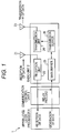
- Fig. 1 is a diagram that illustrates the structure of a node in a method for transmitting and receiving data.
- the node 1 is configured to include a radio unit 2, a communication control unit 3, and an upper-level layer processor 4.
- the node is a general term of devices, which include an FFD and an RFD, executing transmission/reception of data such as transmission, relay, and the like of data.
- the radio unit 2 includes : a reception unit 22 that receives data through a reception antenna 21; a transmission unit 24 that transmits data through a transmission antenna 23; a main buffer 25 that buffers various kinds of data; and a transmission buffer 26 that is disposed between the main buffer 25 and the transmission unit 24 and buffers transmission data transmitted from the main buffer 25 to the transmission unit 24.
- the communication control unit 3 is disposed between the radio unit 2 and the upper-level layer processor 4 and controls the overall radio communication process performed by the radio unit 2.
- the communication control unit 3 extracts payloads included in data received by the reception unit 22 through the reception antenna 21, determines a process to be executed for each payload, and transmits each payload to the main buffer 25 or the upper-level layer processor 4 according to a result of the determination.
- the upper-level layer processor 4 performs various processes for received data and generates various kinds of data relating to the transmission/reception of data such as a new payload and the like.
- Fig. 2 is a diagram that illustrates the appearance of each node 1 periodically performing a standby operation in a method for transmitting and receiving data according to each embodiment of the present invention.
- the periodical standby operation of each node illustrated in Fig. 2 is performed even in the other embodiments to be described later.
- each node performs the periodical standby operation with a specific standby period at a specific interval.
- each node is not constantly in a standby state, in other words, not being in a state in which power is constantly input but being intermittently in a standby state, whereby the waste of power can be prevented.
- FIG. 3 is a diagram that illustrates the appearance of detection of neighboring nodes in the method for transmitting and receiving data.
- a node performing detection of communicable nodes present neighboring thereto repeats transmission of information (hereinafter, referred to as "node information") specific to the request node such as an employed data modulation system and timing at which a data standby operation is performed and a data reception standby operation at a predetermined interval (step S1).
- node information information specific to the request node such as an employed data modulation system and timing at which a data standby operation is performed and a data reception standby operation at a predetermined interval
- the transmission of the node information and the data reception standby operation will be collectively referred to as a discovery operation.
- step S2 other nodes, which are located near the request node, performing a periodical standby operation at an interval specific thereto receive node information transmitted from the request node within the periodical standby operation.
- two nodes hereinafter, referred to as "response nodes 1 and 2" are present near the request node, and these two response nodes 1 and 2 receive the node information from the request node.
- the node information is repeatedly transmitted, and the response nodes 1 and 2 regularly repeat standby operations, whereby there are cases where the transmission timing of the node information from the request node and the standby timing of the response nodes 1 and 2 match each other. As the matching of both the timings occurs in this way, information can be transmitted and received between nodes for which synchronization has not been set up.
- the response nodes 1 and 2 that have received the node information transmitted from the request node transmit node information thereof to the request node, and the request node receives the node information transmitted from the response nodes 1 and 2 within a reception standby operation included in the discovery operation described above (step S3).
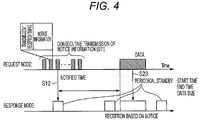
- Fig. 4 is a diagram that illustrates the appearance of data transmission/reception between nodes in a method for transmitting and receiving data.
- the request node consecutively transmits notice information representing data transmission timing that represents timing at which data is transmitted (for example, "after how many seconds from the current time point data is transmitted") and the like to the response node at a predetermined interval for a plurality of number of times (step S11).
- the consecutive transmission of the notice information is performed for a sufficient number of times to extend over about one period of the periodical standby operation of the response node. The reason for this is that, in a case where the consecutive transmission of the notice information is performed a number of times to extend over about one period for increasing the probability of the reception of the notice information in the response node as described above, the response node can reliably receive the notice information.
- the data transmission timing included in the notice information is sequentially shortened from the notice information that is transmitted first. For example, by using the transmission start time point of the notice information transmitted first as the reference, in a case where the data transmission timing included in the first notice information is "after 10 seconds from the current time point", the transmission of the notice information ends after 0.5 seconds, and transmission of the next notice information is started after 1 second after spacing an interval of 0.5 seconds, the data transmission timing included in the next notice information is "9 seconds from the current time point".
- the response node performing the periodical standby operation at a specific interval as described above receives the notice information that is transmitted from the request node (step S12) .
- the response node can reliably receive the notice information, which is desirable.
- each node 1 intermittently performs the standby operation instead of performing a constant standby operation and, also at the time of transmitting/receiving data, may be operated only in a period of time represented in the data transmission timing and perform data standby, transmission and reception operations, and accordingly, the waste of power can be effectively suppressed.
- each node 1 performs a periodical standby operation with a specific standby period at a specific interval.
- a method of detecting neighboring nodes 1 according to this example is performed similar to that of the first example described above, and a request node and a response node are formed.
- Fig. 5 is a diagram that illustrates the appearance of data transmission/reception between nodes 1 in the method for transmitting and receiving data.
- a response node transmits standby information representing timing at which a periodical standby operation is performed to a request node continuously before the periodical standby operation (step S21).
- the standby information is repeatedly transmitted with the same period as that of the periodical standby operation.
- the request node generates data to be transmitted to the request node and performs a standby operation (step S22).
- the request node transmits the generated data to the response node according to timing, at which the response node performs a periodical standby operation, represented in the received standby information, and the response node receives the data (step S23).
- the response node receives the data within the periodical standby operation. In this way, a series of transmission/reception operations of data ends.
- each node 1 intermittently performs the standby operation instead of performing a constant standby operation and, also at the time of transmitting/receiving data, is operated only in a period of time represented in data reception timing and performs data standby, transmission and reception operations. For this reason, the waste of power can be effectively suppressed.
- each node 1 performs a periodical standby operation with a specific standby period at a specific interval.
- a method of detecting neighboring nodes 1 is performed similar to that of the first example described above, and a request node and a response node are formed.
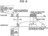
- Fig. 6 is a diagram that illustrates the appearance of data transmission/reception between nodes 1 in the method for transmitting and receiving data according to an embodiment of the present invention.
- a request node consecutively transmits a standby information request requesting standby information representing timing at which a response node performs a periodical standby operation to the response node a plurality of number of times at a predetermined interval and performs a standby operation for the standby information transmitted from the response node to be described later continuously from each transmission of the standby information request that is performed a plurality of number of times (step S31).
- the response node can reliably receive the standby information request, which is desirable.
- the response node that has received the standby information request from the request node transmits standby information to the request node in response to this standby information request (step S32).
- the request node can acquire the timing of the periodical standby operation of the response node based on the standby information received from the response node.
- the request node transmits data to the response node, and the response node receives data transmitted from the request node within the periodical standby operation (step S33).
- each node 1 intermittently performs the standby operation instead of performing a constant standby operation and, also at the time of transmitting/receiving data, is operated only in a period of time represented in data reception timing and performs data standby, transmission and reception operations. For this reason, the waste of power can be effectively suppressed.
- the transmission/reception of data between nodes is not completed within the standby time defined at first.
- the transmission/reception of the data does not need to be completed within the standby time, and, in a case where the transmission/reception of data is not completed within the standby time, even after the end of the standby time, the transmission/reception of data is continuously performed until the completion thereof.
- the standby time can be shortened, and a time during which each node is in a sleep mode can be lengthened, whereby the consumption of power at each node can be effectively suppressed.
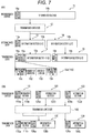
- Fig. 7(A) is a diagram that illustrates the appearance of data division in the method for transmitting and receiving data and Fig. 7 (B) is a diagram that illustrates the appearance of data combination therein.
- generation data 11 that is stored in the transmission buffer 26 of the radio unit 2 that is transmission target data generated by the upper-level layer processor 4 is configured by a header section 11a that is provided for various processes performed in the upper-level layer processor 4 and an information section 11b that is a data main body to be transmitted to another node.
- the transmission target data may be data that is not generated in this node, in other words, relay target data that is received from another node and is transmitted to a further another node.
- the communication control unit 3 determines whether or not the generation data 11 has a size equal to or smaller than a data size 12 of data that can be transmitted by the transmission unit 24. Since this generation data 11 has a size larger than the data size 12 of data that can be transmitted by the transmission unit 24, the data is not smoothly transmitted or cannot be transmitted. Then, by repeating this transmission process until the process is successful, an increase in the power consumption is caused.
- the communication control unit 3 of each node divides the generation data 11 into a plurality of pieces of intermediate data.
- the communication control unit 3 divides the generation data 11 into two pieces of intermediate data 13 and 14 having a data size equal to or less than a transmittable data size.
- the intermediate data 13 has a header section 13a, and the other data generated through the division is the intermediate data 14.
- the communication control unit 3 respectively adds division header sections 15a and 15b to the intermediate data 13 and 14, thereby generating transmission data 15 and 16 that are division data in an actually-transmitted form.
- Each of the division header sections 15a and 15b is configured to include four pieces of data including: data 151 that represents presence/absence of following information of transmission data that is information defining the arrangement order of the intermediate data; data 152 that represents a division number representing the number of pieces of transmission data 15, 16, ⁇ into which the generation data 11 has been divided; data 153 that represents the division order from the header section 11a; and information 154 that represents a sequence number of the original information section 11b of information sections 13b and 14b.
- the communication control unit 3 of each node divides the generation data 11, thereby generating the transmission data 15 and 16.
- the communication control unit 3 sequentially generates intermediate data and transmission data such that the transmission data 15 and 16, which are generated, have a size equal to or less than the data size requested from the transmission unit 24 that manages the transmission of actual information.
- the transmission data 15 and 16 which have been generated are transmitted again from the communication control unit 3 to the transmission unit 24 through the main buffer 25 and the transmission buffer 26 and are transmitted to another node 1.
- each data since each data has a size equal to or less than the data size requested from the transmission unit 24, such data is smoothly transmitted without being delayed.
- the communication control unit 3 of the another node 1 that has received the transmission data 15 and 16 combines such data based on information of the division header sections 15a and 16a included in the transmission data 15 and 16, thereby restoring the original generation data 11.
- the combination of such data will be described more specifically.
- the communication control unit 3 determines that the transmission data 16 is division data of the last part. In addition, since the data representing the division number of the transmission data 16 is "2", the communication control unit 3 determines that the transmission data is a last part of two-divided data and the transmission data 15, which is the other divided data, is previous divided data. This can also be determined based on that the data 153 representing the division order of the transmission data 16 is "2".
- the communication control unit 3 determines that the transmission data 15 is not data of the last part. In addition, since the data representing the division number of the transmission data 15 is "2", the communication control unit 3 determines that the transmission data is not a last part of two-divided data and, in this example, determines that the data 15 is data located in a front-most portion. This can also be determined based on that the data 153 representing the division order of the transmission data 15 is "1".
- the communication control unit 3 can restore the original generation data 11 by combining such data.
- generation data 110, 120, and 130 that are generated by the upper-level layer processor 4 and are stored in the transmission buffer 26 of the radio unit 2, similar to the case illustrated in Fig. 7 (A) , are respectively configured by header sections 110a, 120a, and 130a provided for various processes performed by the upper-level layer processor 4 of another node 1 and information sections 110b, 120b, and 130b that are data main bodies to be transmitted to another node 1.
- the communication control unit 3 first, determines whether or not each of the generation data 110, 120, and 130 has a size that is equal to or less than the transmittable data size 12 of data that can be transmitted by the transmission unit 24.
- each of the generation data 110, 120, and 130 has a size that is much smaller than the data size 140 of data that can be transmitted by the transmission unit 24 of the radio unit 2, it is apparent that the data can be individually transmitted.
- the processing efficiency is low, the processing time increases, and the power consumption increases.
- the communication control unit 3 determines whether or not, in a case where some or all of the generation data 110, 120, and 130 are combined, each combined data has a size equal to or less than the data size 12 of data that can be transmitted by the transmission unit 24.
- the communication control unit 3 generates intermediate data acquired by combining a plurality of pieces of generation data so as to form a combination having a size equal to or less than the data size 12 of data that can be transmitted by the transmission unit 24.
- the communication control unit 3 determines that the transmission data 150 generated by combining two pieces of intermediate data including the intermediate data 110 and 120 of the generation data 11 has a size equal to or less than the transmittable data size 12 of data that can be transmitted by the transmission unit 24.
- the communication control unit 3 actually generates transmission data 150.
- the transmission data 150 is generated by combining a start portion of the generation data 120, in other words, the header section 120a with a last portion of the information section 110b of the generation data 110 to be continuous thereto.
- the information control unit 3 determines to separately transmit the transmission data without combining the generation data 130 therewith.
- the generated transmission data is transmitted to another node.
- the communication control unit 3 of the another node 1 that has received the transmission data determines that a plurality of pieces of the transmission target data 110 and 120 are included in the transmission data based on the information of the header sections 110a and 120a of the plurality of pieces of the transmission target data 110 and 120 included in the transmission data.
- the communication control unit 3 restores the plurality of pieces of the transmission target data 110 and 120 by dividing the transmission data 150.
- the transmittable data size in the lower-level layer is large, by combining a plurality of pieces of small data and transmitting the combined data, the efficiency of the transmission process of data at each node is increased by decreasing the number of times of performing the transmission process, whereby a series of data transmission processes can be performed in a speedy manner, and the power consumption can be suppressed.
Landscapes
- Engineering & Computer Science (AREA)
- Computer Networks & Wireless Communication (AREA)
- Signal Processing (AREA)
- Mobile Radio Communication Systems (AREA)
- Data Exchanges In Wide-Area Networks (AREA)
- Communication Control (AREA)
- Small-Scale Networks (AREA)
Applications Claiming Priority (2)
| Application Number | Priority Date | Filing Date | Title |
|---|---|---|---|
| JP2012255202A JP5645031B2 (ja) | 2012-11-21 | 2012-11-21 | データ送受信方法 |
| PCT/JP2013/006200 WO2014080568A1 (ja) | 2012-11-21 | 2013-10-21 | データ送受信方法 |
Publications (3)
| Publication Number | Publication Date |
|---|---|
| EP2925047A1 EP2925047A1 (en) | 2015-09-30 |
| EP2925047A4 EP2925047A4 (en) | 2016-07-13 |
| EP2925047B1 true EP2925047B1 (en) | 2020-04-15 |
Family
ID=50775766
Family Applications (1)
| Application Number | Title | Priority Date | Filing Date |
|---|---|---|---|
| EP13857539.4A Active EP2925047B1 (en) | 2012-11-21 | 2013-10-21 | Method for transmitting and receiving data |
Country Status (5)
| Country | Link |
|---|---|
| US (1) | US9509517B2 (enExample) |
| EP (1) | EP2925047B1 (enExample) |
| JP (1) | JP5645031B2 (enExample) |
| CN (1) | CN104798399B (enExample) |
| WO (1) | WO2014080568A1 (enExample) |
Families Citing this family (9)
| Publication number | Priority date | Publication date | Assignee | Title |
|---|---|---|---|---|
| JP5645032B2 (ja) | 2012-11-21 | 2014-12-24 | 独立行政法人情報通信研究機構 | データ送受信方法 |
| JP5645031B2 (ja) | 2012-11-21 | 2014-12-24 | 独立行政法人情報通信研究機構 | データ送受信方法 |
| JP6675408B2 (ja) * | 2015-09-10 | 2020-04-01 | 富士フイルム株式会社 | 情報処理システム、情報処理方法、情報処理プログラム、及び記憶媒体 |
| CN109076459A (zh) * | 2016-05-13 | 2018-12-21 | 索尼移动通信株式会社 | 用于传输数据的通信装置和方法 |
| JP6594365B2 (ja) * | 2017-03-22 | 2019-10-23 | 株式会社東芝 | 無線通信装置及び無線通信システム |
| US11218981B2 (en) * | 2018-09-20 | 2022-01-04 | Kabushiki Kaisha Toshiba | Wireless mesh network and data transmission method |
| JP6823133B2 (ja) * | 2019-09-17 | 2021-01-27 | 株式会社東芝 | 無線通信装置及び無線通信システム |
| US11706682B2 (en) | 2020-12-22 | 2023-07-18 | Google Llc | Switchable communication transport for communication between primary devices and vehicle head units |
| US11477626B2 (en) * | 2020-12-22 | 2022-10-18 | Google Llc | Method and system for segmenting and transmiting data between computing devices and vehicle head units |
Family Cites Families (16)
| Publication number | Priority date | Publication date | Assignee | Title |
|---|---|---|---|---|
| JP3297763B2 (ja) | 1993-02-01 | 2002-07-02 | ソニー株式会社 | データ伝送方法、コンセントレータ及び端末装置 |
| KR100532274B1 (ko) * | 1999-09-08 | 2005-11-29 | 삼성전자주식회사 | 디지털 휴대용 단말기의 장문 메시지 송수신장치 및 그 방법 |
| JP2005101756A (ja) | 2003-09-22 | 2005-04-14 | Sony Corp | 無線通信システム、無線通信装置及び無線通信方法、並びにコンピュータ・プログラム |
| US7768988B2 (en) * | 2005-02-22 | 2010-08-03 | Intel Corporation | Method and apparatus to perform network medium reservation in a wireless network |
| EP1764980B8 (en) * | 2005-09-20 | 2009-01-07 | Panasonic Corporation | Method and apparatus for packet segmentation and concatenation signaling in a communication system |
| RU2409898C2 (ru) * | 2006-01-05 | 2011-01-20 | Нокиа Корпорейшн | Гибкая схема сегментации для систем связи |
| US8255537B2 (en) | 2007-02-14 | 2012-08-28 | Mitsubishi Electric Corporation | Vehicle communication device |
| KR100932909B1 (ko) * | 2007-11-09 | 2009-12-21 | 한국전자통신연구원 | 무선 센서 네트워크에 있어서의 코디네이터 장치 및 그 운용 방법 |
| JP5200826B2 (ja) * | 2008-09-29 | 2013-06-05 | 株式会社国際電気通信基礎技術研究所 | 無線装置およびそれを備えた無線ネットワーク |
| US20110038313A1 (en) * | 2009-08-12 | 2011-02-17 | Electronics And Telecommunications Research Institute | Enhanced communication apparatus for providing enhanced concatenation, segmentation and reassembly of service data units |
| EP2548392B1 (en) * | 2010-03-16 | 2013-11-13 | ABB Research Ltd. | An energy efficient method for communication in a wireless sensor network of an industrial control system. |
| JP5569452B2 (ja) * | 2011-03-30 | 2014-08-13 | 沖電気工業株式会社 | 無線通信装置、方法及びプログラム |
| JP6024064B2 (ja) * | 2012-07-23 | 2016-11-09 | 国立研究開発法人情報通信研究機構 | データ送受信方法 |
| JP6020994B2 (ja) * | 2012-07-23 | 2016-11-02 | 国立研究開発法人情報通信研究機構 | データ送受信方法 |
| JP5645031B2 (ja) | 2012-11-21 | 2014-12-24 | 独立行政法人情報通信研究機構 | データ送受信方法 |
| JP5645032B2 (ja) * | 2012-11-21 | 2014-12-24 | 独立行政法人情報通信研究機構 | データ送受信方法 |
-
2012
- 2012-11-21 JP JP2012255202A patent/JP5645031B2/ja active Active
-
2013
- 2013-10-21 CN CN201380060607.2A patent/CN104798399B/zh active Active
- 2013-10-21 US US14/443,840 patent/US9509517B2/en active Active
- 2013-10-21 EP EP13857539.4A patent/EP2925047B1/en active Active
- 2013-10-21 WO PCT/JP2013/006200 patent/WO2014080568A1/ja not_active Ceased
Non-Patent Citations (1)
| Title |
|---|
| None * |
Also Published As
| Publication number | Publication date |
|---|---|
| EP2925047A1 (en) | 2015-09-30 |
| CN104798399A (zh) | 2015-07-22 |
| CN104798399B (zh) | 2019-01-11 |
| JP2014103580A (ja) | 2014-06-05 |
| US9509517B2 (en) | 2016-11-29 |
| WO2014080568A1 (ja) | 2014-05-30 |
| JP5645031B2 (ja) | 2014-12-24 |
| US20150319001A1 (en) | 2015-11-05 |
| EP2925047A4 (en) | 2016-07-13 |
Similar Documents
| Publication | Publication Date | Title |
|---|---|---|
| EP2925047B1 (en) | Method for transmitting and receiving data | |
| EP2915260B1 (en) | Fast frequency-hopping schedule recovery | |
| US8223680B2 (en) | Mesh network control using common designation wake-up | |
| JP2023075220A (ja) | 広域エネルギ回収センサ・ネットワーク展開のためのマルチホップ・ネットワーキング・プロトコル | |
| EP3128783B1 (en) | Wireless communication method | |
| US9699726B2 (en) | Data-transmitting/receiving method for effectively suppressing power consumption | |
| US9674780B2 (en) | Data transmitting/receiving method | |
| JP5366920B2 (ja) | 無線通信システム、無線通信方法及び無線通信プログラム | |
| Bernard et al. | A low energy consumption MAC protocol for WSN | |
| US9538365B2 (en) | Method for transmitting and receiving data | |
| CN107710849A (zh) | Tsch无线通信网络中的自适应时隙分配 | |
| Dang et al. | A hybrid multi-channel MAC protocol for wireless ad hoc networks | |
| JP5082590B2 (ja) | 通信装置および通信ネットワーク | |
| US8934596B2 (en) | Methods and apparatuses for synchronization of wireless devices in wireless networks | |
| JP2022548363A (ja) | 無線通信ネットワークのための分散型同期ソリューション | |
| Kumberg et al. | Improving the performance of the cross-layer wake-up routing protocol T-ROME | |
| Takyu et al. | Optimization of learning time for learning-assisted rendezvous channel in cognitive radio system | |
| Wolf et al. | Distributed formation of broadcast transmission schedules for mobile ad hoc networks | |
| Sokullu et al. | MAC layer protocols for linear wireless sensor networks: a survey | |
| KR101465138B1 (ko) | 온디멘드 방식의 모바일 애드혹 네트워크 라우팅에서의 헬로 패킷 스케줄링 방법 및 연결 제어 방법 | |
| CN104936271A (zh) | 通信装置、无线通信系统和通信方法 | |
| Yoo et al. | Medium access control with dynamic frame length in wireless sensor networks | |
| Kang et al. | A fast ad-hoc neighbor discovery algorithm based on a friend trust mechanism | |
| Hsu et al. | The analysis of a multi-channel MAC protocol using maximal matching for ad hoc networks | |
| Sheikh et al. | Distributive and self-sustainable scheduling algorithm for wireless sensor networks |
Legal Events
| Date | Code | Title | Description |
|---|---|---|---|
| PUAI | Public reference made under article 153(3) epc to a published international application that has entered the european phase |
Free format text: ORIGINAL CODE: 0009012 |
|
| 17P | Request for examination filed |
Effective date: 20150518 |
|
| AK | Designated contracting states |
Kind code of ref document: A1 Designated state(s): AL AT BE BG CH CY CZ DE DK EE ES FI FR GB GR HR HU IE IS IT LI LT LU LV MC MK MT NL NO PL PT RO RS SE SI SK SM TR |
|
| AX | Request for extension of the european patent |
Extension state: BA ME |
|
| DAX | Request for extension of the european patent (deleted) | ||
| RA4 | Supplementary search report drawn up and despatched (corrected) |
Effective date: 20160613 |
|
| RIC1 | Information provided on ipc code assigned before grant |
Ipc: H04W 52/02 20090101ALN20160607BHEP Ipc: H04W 28/06 20090101AFI20160607BHEP |
|
| STAA | Information on the status of an ep patent application or granted ep patent |
Free format text: STATUS: EXAMINATION IS IN PROGRESS |
|
| 17Q | First examination report despatched |
Effective date: 20180416 |
|
| RAP1 | Party data changed (applicant data changed or rights of an application transferred) |
Owner name: NATIONAL INSTITUTE OF INFORMATION AND COMMUNICATIO |
|
| RIC1 | Information provided on ipc code assigned before grant |
Ipc: H04W 28/06 20090101AFI20191003BHEP Ipc: H04W 68/00 20090101ALN20191003BHEP Ipc: H04W 52/02 20090101ALI20191003BHEP |
|
| GRAP | Despatch of communication of intention to grant a patent |
Free format text: ORIGINAL CODE: EPIDOSNIGR1 |
|
| STAA | Information on the status of an ep patent application or granted ep patent |
Free format text: STATUS: GRANT OF PATENT IS INTENDED |
|
| INTG | Intention to grant announced |
Effective date: 20191121 |
|
| RIC1 | Information provided on ipc code assigned before grant |
Ipc: H04W 68/00 20090101ALN20191113BHEP Ipc: H04W 52/02 20090101ALI20191113BHEP Ipc: H04W 28/06 20090101AFI20191113BHEP |
|
| GRAS | Grant fee paid |
Free format text: ORIGINAL CODE: EPIDOSNIGR3 |
|
| GRAA | (expected) grant |
Free format text: ORIGINAL CODE: 0009210 |
|
| STAA | Information on the status of an ep patent application or granted ep patent |
Free format text: STATUS: THE PATENT HAS BEEN GRANTED |
|
| AK | Designated contracting states |
Kind code of ref document: B1 Designated state(s): AL AT BE BG CH CY CZ DE DK EE ES FI FR GB GR HR HU IE IS IT LI LT LU LV MC MK MT NL NO PL PT RO RS SE SI SK SM TR |
|
| REG | Reference to a national code |
Ref country code: CH Ref legal event code: EP |
|
| REG | Reference to a national code |
Ref country code: DE Ref legal event code: R096 Ref document number: 602013068035 Country of ref document: DE |
|
| REG | Reference to a national code |
Ref country code: IE Ref legal event code: FG4D |
|
| REG | Reference to a national code |
Ref country code: AT Ref legal event code: REF Ref document number: 1258736 Country of ref document: AT Kind code of ref document: T Effective date: 20200515 |
|
| REG | Reference to a national code |
Ref country code: NL Ref legal event code: MP Effective date: 20200415 |
|
| REG | Reference to a national code |
Ref country code: LT Ref legal event code: MG4D |
|
| PG25 | Lapsed in a contracting state [announced via postgrant information from national office to epo] |
Ref country code: FI Free format text: LAPSE BECAUSE OF FAILURE TO SUBMIT A TRANSLATION OF THE DESCRIPTION OR TO PAY THE FEE WITHIN THE PRESCRIBED TIME-LIMIT Effective date: 20200415 Ref country code: PT Free format text: LAPSE BECAUSE OF FAILURE TO SUBMIT A TRANSLATION OF THE DESCRIPTION OR TO PAY THE FEE WITHIN THE PRESCRIBED TIME-LIMIT Effective date: 20200817 Ref country code: LT Free format text: LAPSE BECAUSE OF FAILURE TO SUBMIT A TRANSLATION OF THE DESCRIPTION OR TO PAY THE FEE WITHIN THE PRESCRIBED TIME-LIMIT Effective date: 20200415 Ref country code: NL Free format text: LAPSE BECAUSE OF FAILURE TO SUBMIT A TRANSLATION OF THE DESCRIPTION OR TO PAY THE FEE WITHIN THE PRESCRIBED TIME-LIMIT Effective date: 20200415 Ref country code: GR Free format text: LAPSE BECAUSE OF FAILURE TO SUBMIT A TRANSLATION OF THE DESCRIPTION OR TO PAY THE FEE WITHIN THE PRESCRIBED TIME-LIMIT Effective date: 20200716 Ref country code: NO Free format text: LAPSE BECAUSE OF FAILURE TO SUBMIT A TRANSLATION OF THE DESCRIPTION OR TO PAY THE FEE WITHIN THE PRESCRIBED TIME-LIMIT Effective date: 20200715 Ref country code: IS Free format text: LAPSE BECAUSE OF FAILURE TO SUBMIT A TRANSLATION OF THE DESCRIPTION OR TO PAY THE FEE WITHIN THE PRESCRIBED TIME-LIMIT Effective date: 20200815 Ref country code: SE Free format text: LAPSE BECAUSE OF FAILURE TO SUBMIT A TRANSLATION OF THE DESCRIPTION OR TO PAY THE FEE WITHIN THE PRESCRIBED TIME-LIMIT Effective date: 20200415 |
|
| REG | Reference to a national code |
Ref country code: AT Ref legal event code: MK05 Ref document number: 1258736 Country of ref document: AT Kind code of ref document: T Effective date: 20200415 |
|
| PG25 | Lapsed in a contracting state [announced via postgrant information from national office to epo] |
Ref country code: BG Free format text: LAPSE BECAUSE OF FAILURE TO SUBMIT A TRANSLATION OF THE DESCRIPTION OR TO PAY THE FEE WITHIN THE PRESCRIBED TIME-LIMIT Effective date: 20200715 Ref country code: HR Free format text: LAPSE BECAUSE OF FAILURE TO SUBMIT A TRANSLATION OF THE DESCRIPTION OR TO PAY THE FEE WITHIN THE PRESCRIBED TIME-LIMIT Effective date: 20200415 Ref country code: RS Free format text: LAPSE BECAUSE OF FAILURE TO SUBMIT A TRANSLATION OF THE DESCRIPTION OR TO PAY THE FEE WITHIN THE PRESCRIBED TIME-LIMIT Effective date: 20200415 Ref country code: LV Free format text: LAPSE BECAUSE OF FAILURE TO SUBMIT A TRANSLATION OF THE DESCRIPTION OR TO PAY THE FEE WITHIN THE PRESCRIBED TIME-LIMIT Effective date: 20200415 |
|
| PG25 | Lapsed in a contracting state [announced via postgrant information from national office to epo] |
Ref country code: AL Free format text: LAPSE BECAUSE OF FAILURE TO SUBMIT A TRANSLATION OF THE DESCRIPTION OR TO PAY THE FEE WITHIN THE PRESCRIBED TIME-LIMIT Effective date: 20200415 |
|
| REG | Reference to a national code |
Ref country code: DE Ref legal event code: R097 Ref document number: 602013068035 Country of ref document: DE |
|
| PG25 | Lapsed in a contracting state [announced via postgrant information from national office to epo] |
Ref country code: ES Free format text: LAPSE BECAUSE OF FAILURE TO SUBMIT A TRANSLATION OF THE DESCRIPTION OR TO PAY THE FEE WITHIN THE PRESCRIBED TIME-LIMIT Effective date: 20200415 Ref country code: DK Free format text: LAPSE BECAUSE OF FAILURE TO SUBMIT A TRANSLATION OF THE DESCRIPTION OR TO PAY THE FEE WITHIN THE PRESCRIBED TIME-LIMIT Effective date: 20200415 Ref country code: AT Free format text: LAPSE BECAUSE OF FAILURE TO SUBMIT A TRANSLATION OF THE DESCRIPTION OR TO PAY THE FEE WITHIN THE PRESCRIBED TIME-LIMIT Effective date: 20200415 Ref country code: EE Free format text: LAPSE BECAUSE OF FAILURE TO SUBMIT A TRANSLATION OF THE DESCRIPTION OR TO PAY THE FEE WITHIN THE PRESCRIBED TIME-LIMIT Effective date: 20200415 Ref country code: CZ Free format text: LAPSE BECAUSE OF FAILURE TO SUBMIT A TRANSLATION OF THE DESCRIPTION OR TO PAY THE FEE WITHIN THE PRESCRIBED TIME-LIMIT Effective date: 20200415 Ref country code: RO Free format text: LAPSE BECAUSE OF FAILURE TO SUBMIT A TRANSLATION OF THE DESCRIPTION OR TO PAY THE FEE WITHIN THE PRESCRIBED TIME-LIMIT Effective date: 20200415 Ref country code: SM Free format text: LAPSE BECAUSE OF FAILURE TO SUBMIT A TRANSLATION OF THE DESCRIPTION OR TO PAY THE FEE WITHIN THE PRESCRIBED TIME-LIMIT Effective date: 20200415 Ref country code: IT Free format text: LAPSE BECAUSE OF FAILURE TO SUBMIT A TRANSLATION OF THE DESCRIPTION OR TO PAY THE FEE WITHIN THE PRESCRIBED TIME-LIMIT Effective date: 20200415 |
|
| PLBE | No opposition filed within time limit |
Free format text: ORIGINAL CODE: 0009261 |
|
| STAA | Information on the status of an ep patent application or granted ep patent |
Free format text: STATUS: NO OPPOSITION FILED WITHIN TIME LIMIT |
|
| PG25 | Lapsed in a contracting state [announced via postgrant information from national office to epo] |
Ref country code: SK Free format text: LAPSE BECAUSE OF FAILURE TO SUBMIT A TRANSLATION OF THE DESCRIPTION OR TO PAY THE FEE WITHIN THE PRESCRIBED TIME-LIMIT Effective date: 20200415 Ref country code: PL Free format text: LAPSE BECAUSE OF FAILURE TO SUBMIT A TRANSLATION OF THE DESCRIPTION OR TO PAY THE FEE WITHIN THE PRESCRIBED TIME-LIMIT Effective date: 20200415 |
|
| 26N | No opposition filed |
Effective date: 20210118 |
|
| REG | Reference to a national code |
Ref country code: DE Ref legal event code: R119 Ref document number: 602013068035 Country of ref document: DE |
|
| PG25 | Lapsed in a contracting state [announced via postgrant information from national office to epo] |
Ref country code: SI Free format text: LAPSE BECAUSE OF FAILURE TO SUBMIT A TRANSLATION OF THE DESCRIPTION OR TO PAY THE FEE WITHIN THE PRESCRIBED TIME-LIMIT Effective date: 20200415 |
|
| REG | Reference to a national code |
Ref country code: CH Ref legal event code: PL |
|
| PG25 | Lapsed in a contracting state [announced via postgrant information from national office to epo] |
Ref country code: MC Free format text: LAPSE BECAUSE OF FAILURE TO SUBMIT A TRANSLATION OF THE DESCRIPTION OR TO PAY THE FEE WITHIN THE PRESCRIBED TIME-LIMIT Effective date: 20200415 Ref country code: LU Free format text: LAPSE BECAUSE OF NON-PAYMENT OF DUE FEES Effective date: 20201021 |
|
| REG | Reference to a national code |
Ref country code: BE Ref legal event code: MM Effective date: 20201031 |
|
| PG25 | Lapsed in a contracting state [announced via postgrant information from national office to epo] |
Ref country code: DE Free format text: LAPSE BECAUSE OF NON-PAYMENT OF DUE FEES Effective date: 20210501 |
|
| PG25 | Lapsed in a contracting state [announced via postgrant information from national office to epo] |
Ref country code: LI Free format text: LAPSE BECAUSE OF NON-PAYMENT OF DUE FEES Effective date: 20201031 Ref country code: CH Free format text: LAPSE BECAUSE OF NON-PAYMENT OF DUE FEES Effective date: 20201031 Ref country code: BE Free format text: LAPSE BECAUSE OF NON-PAYMENT OF DUE FEES Effective date: 20201031 |
|
| PG25 | Lapsed in a contracting state [announced via postgrant information from national office to epo] |
Ref country code: IE Free format text: LAPSE BECAUSE OF NON-PAYMENT OF DUE FEES Effective date: 20201021 |
|
| PG25 | Lapsed in a contracting state [announced via postgrant information from national office to epo] |
Ref country code: TR Free format text: LAPSE BECAUSE OF FAILURE TO SUBMIT A TRANSLATION OF THE DESCRIPTION OR TO PAY THE FEE WITHIN THE PRESCRIBED TIME-LIMIT Effective date: 20200415 Ref country code: MT Free format text: LAPSE BECAUSE OF FAILURE TO SUBMIT A TRANSLATION OF THE DESCRIPTION OR TO PAY THE FEE WITHIN THE PRESCRIBED TIME-LIMIT Effective date: 20200415 Ref country code: CY Free format text: LAPSE BECAUSE OF FAILURE TO SUBMIT A TRANSLATION OF THE DESCRIPTION OR TO PAY THE FEE WITHIN THE PRESCRIBED TIME-LIMIT Effective date: 20200415 |
|
| PG25 | Lapsed in a contracting state [announced via postgrant information from national office to epo] |
Ref country code: MK Free format text: LAPSE BECAUSE OF FAILURE TO SUBMIT A TRANSLATION OF THE DESCRIPTION OR TO PAY THE FEE WITHIN THE PRESCRIBED TIME-LIMIT Effective date: 20200415 |
|
| PGFP | Annual fee paid to national office [announced via postgrant information from national office to epo] |
Ref country code: GB Payment date: 20251022 Year of fee payment: 13 |
|
| PGFP | Annual fee paid to national office [announced via postgrant information from national office to epo] |
Ref country code: FR Payment date: 20251030 Year of fee payment: 13 |