EP2924876A1 - Inverter device - Google Patents
Inverter device Download PDFInfo
- Publication number
- EP2924876A1 EP2924876A1 EP13856547.8A EP13856547A EP2924876A1 EP 2924876 A1 EP2924876 A1 EP 2924876A1 EP 13856547 A EP13856547 A EP 13856547A EP 2924876 A1 EP2924876 A1 EP 2924876A1
- Authority
- EP
- European Patent Office
- Prior art keywords
- capacitor
- temperature
- deterioration
- degree
- inverter
- Prior art date
- Legal status (The legal status is an assumption and is not a legal conclusion. Google has not performed a legal analysis and makes no representation as to the accuracy of the status listed.)
- Withdrawn
Links
- 239000003990 capacitor Substances 0.000 claims abstract description 123
- 230000006866 deterioration Effects 0.000 claims abstract description 42
- 230000004913 activation Effects 0.000 claims description 13
- 238000010586 diagram Methods 0.000 description 4
- 230000006870 function Effects 0.000 description 3
- 230000007774 longterm Effects 0.000 description 2
- 238000000034 method Methods 0.000 description 2
- 230000008929 regeneration Effects 0.000 description 2
- 238000011069 regeneration method Methods 0.000 description 2
- 230000004044 response Effects 0.000 description 2
- 230000003247 decreasing effect Effects 0.000 description 1
- 238000001514 detection method Methods 0.000 description 1
- 238000005259 measurement Methods 0.000 description 1
- 230000001172 regenerating effect Effects 0.000 description 1
Images


Classifications
-
- H—ELECTRICITY
- H02—GENERATION; CONVERSION OR DISTRIBUTION OF ELECTRIC POWER
- H02M—APPARATUS FOR CONVERSION BETWEEN AC AND AC, BETWEEN AC AND DC, OR BETWEEN DC AND DC, AND FOR USE WITH MAINS OR SIMILAR POWER SUPPLY SYSTEMS; CONVERSION OF DC OR AC INPUT POWER INTO SURGE OUTPUT POWER; CONTROL OR REGULATION THEREOF
- H02M1/00—Details of apparatus for conversion
- H02M1/36—Means for starting or stopping converters
-
- B—PERFORMING OPERATIONS; TRANSPORTING
- B60—VEHICLES IN GENERAL
- B60L—PROPULSION OF ELECTRICALLY-PROPELLED VEHICLES; SUPPLYING ELECTRIC POWER FOR AUXILIARY EQUIPMENT OF ELECTRICALLY-PROPELLED VEHICLES; ELECTRODYNAMIC BRAKE SYSTEMS FOR VEHICLES IN GENERAL; MAGNETIC SUSPENSION OR LEVITATION FOR VEHICLES; MONITORING OPERATING VARIABLES OF ELECTRICALLY-PROPELLED VEHICLES; ELECTRIC SAFETY DEVICES FOR ELECTRICALLY-PROPELLED VEHICLES
- B60L15/00—Methods, circuits, or devices for controlling the traction-motor speed of electrically-propelled vehicles
- B60L15/007—Physical arrangements or structures of drive train converters specially adapted for the propulsion motors of electric vehicles
-
- B—PERFORMING OPERATIONS; TRANSPORTING
- B60—VEHICLES IN GENERAL
- B60L—PROPULSION OF ELECTRICALLY-PROPELLED VEHICLES; SUPPLYING ELECTRIC POWER FOR AUXILIARY EQUIPMENT OF ELECTRICALLY-PROPELLED VEHICLES; ELECTRODYNAMIC BRAKE SYSTEMS FOR VEHICLES IN GENERAL; MAGNETIC SUSPENSION OR LEVITATION FOR VEHICLES; MONITORING OPERATING VARIABLES OF ELECTRICALLY-PROPELLED VEHICLES; ELECTRIC SAFETY DEVICES FOR ELECTRICALLY-PROPELLED VEHICLES
- B60L3/00—Electric devices on electrically-propelled vehicles for safety purposes; Monitoring operating variables, e.g. speed, deceleration or energy consumption
- B60L3/0023—Detecting, eliminating, remedying or compensating for drive train abnormalities, e.g. failures within the drive train
- B60L3/0046—Detecting, eliminating, remedying or compensating for drive train abnormalities, e.g. failures within the drive train relating to electric energy storage systems, e.g. batteries or capacitors
-
- B—PERFORMING OPERATIONS; TRANSPORTING
- B60—VEHICLES IN GENERAL
- B60L—PROPULSION OF ELECTRICALLY-PROPELLED VEHICLES; SUPPLYING ELECTRIC POWER FOR AUXILIARY EQUIPMENT OF ELECTRICALLY-PROPELLED VEHICLES; ELECTRODYNAMIC BRAKE SYSTEMS FOR VEHICLES IN GENERAL; MAGNETIC SUSPENSION OR LEVITATION FOR VEHICLES; MONITORING OPERATING VARIABLES OF ELECTRICALLY-PROPELLED VEHICLES; ELECTRIC SAFETY DEVICES FOR ELECTRICALLY-PROPELLED VEHICLES
- B60L50/00—Electric propulsion with power supplied within the vehicle
- B60L50/50—Electric propulsion with power supplied within the vehicle using propulsion power supplied by batteries or fuel cells
- B60L50/51—Electric propulsion with power supplied within the vehicle using propulsion power supplied by batteries or fuel cells characterised by AC-motors
-
- H—ELECTRICITY
- H02—GENERATION; CONVERSION OR DISTRIBUTION OF ELECTRIC POWER
- H02M—APPARATUS FOR CONVERSION BETWEEN AC AND AC, BETWEEN AC AND DC, OR BETWEEN DC AND DC, AND FOR USE WITH MAINS OR SIMILAR POWER SUPPLY SYSTEMS; CONVERSION OF DC OR AC INPUT POWER INTO SURGE OUTPUT POWER; CONTROL OR REGULATION THEREOF
- H02M1/00—Details of apparatus for conversion
- H02M1/32—Means for protecting converters other than automatic disconnection
-
- H—ELECTRICITY
- H02—GENERATION; CONVERSION OR DISTRIBUTION OF ELECTRIC POWER
- H02M—APPARATUS FOR CONVERSION BETWEEN AC AND AC, BETWEEN AC AND DC, OR BETWEEN DC AND DC, AND FOR USE WITH MAINS OR SIMILAR POWER SUPPLY SYSTEMS; CONVERSION OF DC OR AC INPUT POWER INTO SURGE OUTPUT POWER; CONTROL OR REGULATION THEREOF
- H02M7/00—Conversion of AC power input into DC power output; Conversion of DC power input into AC power output
- H02M7/42—Conversion of DC power input into AC power output without possibility of reversal
- H02M7/44—Conversion of DC power input into AC power output without possibility of reversal by static converters
- H02M7/48—Conversion of DC power input into AC power output without possibility of reversal by static converters using discharge tubes with control electrode or semiconductor devices with control electrode
- H02M7/53—Conversion of DC power input into AC power output without possibility of reversal by static converters using discharge tubes with control electrode or semiconductor devices with control electrode using devices of a triode or transistor type requiring continuous application of a control signal
- H02M7/537—Conversion of DC power input into AC power output without possibility of reversal by static converters using discharge tubes with control electrode or semiconductor devices with control electrode using devices of a triode or transistor type requiring continuous application of a control signal using semiconductor devices only, e.g. single switched pulse inverters
- H02M7/5375—Conversion of DC power input into AC power output without possibility of reversal by static converters using discharge tubes with control electrode or semiconductor devices with control electrode using devices of a triode or transistor type requiring continuous application of a control signal using semiconductor devices only, e.g. single switched pulse inverters with special starting equipment
-
- B—PERFORMING OPERATIONS; TRANSPORTING
- B60—VEHICLES IN GENERAL
- B60L—PROPULSION OF ELECTRICALLY-PROPELLED VEHICLES; SUPPLYING ELECTRIC POWER FOR AUXILIARY EQUIPMENT OF ELECTRICALLY-PROPELLED VEHICLES; ELECTRODYNAMIC BRAKE SYSTEMS FOR VEHICLES IN GENERAL; MAGNETIC SUSPENSION OR LEVITATION FOR VEHICLES; MONITORING OPERATING VARIABLES OF ELECTRICALLY-PROPELLED VEHICLES; ELECTRIC SAFETY DEVICES FOR ELECTRICALLY-PROPELLED VEHICLES
- B60L2200/00—Type of vehicles
- B60L2200/40—Working vehicles
- B60L2200/42—Fork lift trucks
-
- B—PERFORMING OPERATIONS; TRANSPORTING
- B60—VEHICLES IN GENERAL
- B60L—PROPULSION OF ELECTRICALLY-PROPELLED VEHICLES; SUPPLYING ELECTRIC POWER FOR AUXILIARY EQUIPMENT OF ELECTRICALLY-PROPELLED VEHICLES; ELECTRODYNAMIC BRAKE SYSTEMS FOR VEHICLES IN GENERAL; MAGNETIC SUSPENSION OR LEVITATION FOR VEHICLES; MONITORING OPERATING VARIABLES OF ELECTRICALLY-PROPELLED VEHICLES; ELECTRIC SAFETY DEVICES FOR ELECTRICALLY-PROPELLED VEHICLES
- B60L2210/00—Converter types
- B60L2210/30—AC to DC converters
-
- B—PERFORMING OPERATIONS; TRANSPORTING
- B60—VEHICLES IN GENERAL
- B60L—PROPULSION OF ELECTRICALLY-PROPELLED VEHICLES; SUPPLYING ELECTRIC POWER FOR AUXILIARY EQUIPMENT OF ELECTRICALLY-PROPELLED VEHICLES; ELECTRODYNAMIC BRAKE SYSTEMS FOR VEHICLES IN GENERAL; MAGNETIC SUSPENSION OR LEVITATION FOR VEHICLES; MONITORING OPERATING VARIABLES OF ELECTRICALLY-PROPELLED VEHICLES; ELECTRIC SAFETY DEVICES FOR ELECTRICALLY-PROPELLED VEHICLES
- B60L2210/00—Converter types
- B60L2210/40—DC to AC converters
- B60L2210/42—Voltage source inverters
-
- B—PERFORMING OPERATIONS; TRANSPORTING
- B60—VEHICLES IN GENERAL
- B60L—PROPULSION OF ELECTRICALLY-PROPELLED VEHICLES; SUPPLYING ELECTRIC POWER FOR AUXILIARY EQUIPMENT OF ELECTRICALLY-PROPELLED VEHICLES; ELECTRODYNAMIC BRAKE SYSTEMS FOR VEHICLES IN GENERAL; MAGNETIC SUSPENSION OR LEVITATION FOR VEHICLES; MONITORING OPERATING VARIABLES OF ELECTRICALLY-PROPELLED VEHICLES; ELECTRIC SAFETY DEVICES FOR ELECTRICALLY-PROPELLED VEHICLES
- B60L2240/00—Control parameters of input or output; Target parameters
- B60L2240/10—Vehicle control parameters
- B60L2240/36—Temperature of vehicle components or parts
-
- B—PERFORMING OPERATIONS; TRANSPORTING
- B60—VEHICLES IN GENERAL
- B60L—PROPULSION OF ELECTRICALLY-PROPELLED VEHICLES; SUPPLYING ELECTRIC POWER FOR AUXILIARY EQUIPMENT OF ELECTRICALLY-PROPELLED VEHICLES; ELECTRODYNAMIC BRAKE SYSTEMS FOR VEHICLES IN GENERAL; MAGNETIC SUSPENSION OR LEVITATION FOR VEHICLES; MONITORING OPERATING VARIABLES OF ELECTRICALLY-PROPELLED VEHICLES; ELECTRIC SAFETY DEVICES FOR ELECTRICALLY-PROPELLED VEHICLES
- B60L2240/00—Control parameters of input or output; Target parameters
- B60L2240/40—Drive Train control parameters
- B60L2240/52—Drive Train control parameters related to converters
- B60L2240/525—Temperature of converter or components thereof
-
- B—PERFORMING OPERATIONS; TRANSPORTING
- B60—VEHICLES IN GENERAL
- B60L—PROPULSION OF ELECTRICALLY-PROPELLED VEHICLES; SUPPLYING ELECTRIC POWER FOR AUXILIARY EQUIPMENT OF ELECTRICALLY-PROPELLED VEHICLES; ELECTRODYNAMIC BRAKE SYSTEMS FOR VEHICLES IN GENERAL; MAGNETIC SUSPENSION OR LEVITATION FOR VEHICLES; MONITORING OPERATING VARIABLES OF ELECTRICALLY-PROPELLED VEHICLES; ELECTRIC SAFETY DEVICES FOR ELECTRICALLY-PROPELLED VEHICLES
- B60L2240/00—Control parameters of input or output; Target parameters
- B60L2240/40—Drive Train control parameters
- B60L2240/52—Drive Train control parameters related to converters
- B60L2240/526—Operating parameters
-
- B—PERFORMING OPERATIONS; TRANSPORTING
- B60—VEHICLES IN GENERAL
- B60L—PROPULSION OF ELECTRICALLY-PROPELLED VEHICLES; SUPPLYING ELECTRIC POWER FOR AUXILIARY EQUIPMENT OF ELECTRICALLY-PROPELLED VEHICLES; ELECTRODYNAMIC BRAKE SYSTEMS FOR VEHICLES IN GENERAL; MAGNETIC SUSPENSION OR LEVITATION FOR VEHICLES; MONITORING OPERATING VARIABLES OF ELECTRICALLY-PROPELLED VEHICLES; ELECTRIC SAFETY DEVICES FOR ELECTRICALLY-PROPELLED VEHICLES
- B60L2240/00—Control parameters of input or output; Target parameters
- B60L2240/40—Drive Train control parameters
- B60L2240/52—Drive Train control parameters related to converters
- B60L2240/529—Current
-
- B—PERFORMING OPERATIONS; TRANSPORTING
- B60—VEHICLES IN GENERAL
- B60L—PROPULSION OF ELECTRICALLY-PROPELLED VEHICLES; SUPPLYING ELECTRIC POWER FOR AUXILIARY EQUIPMENT OF ELECTRICALLY-PROPELLED VEHICLES; ELECTRODYNAMIC BRAKE SYSTEMS FOR VEHICLES IN GENERAL; MAGNETIC SUSPENSION OR LEVITATION FOR VEHICLES; MONITORING OPERATING VARIABLES OF ELECTRICALLY-PROPELLED VEHICLES; ELECTRIC SAFETY DEVICES FOR ELECTRICALLY-PROPELLED VEHICLES
- B60L2240/00—Control parameters of input or output; Target parameters
- B60L2240/40—Drive Train control parameters
- B60L2240/54—Drive Train control parameters related to batteries
- B60L2240/549—Current
-
- H—ELECTRICITY
- H02—GENERATION; CONVERSION OR DISTRIBUTION OF ELECTRIC POWER
- H02M—APPARATUS FOR CONVERSION BETWEEN AC AND AC, BETWEEN AC AND DC, OR BETWEEN DC AND DC, AND FOR USE WITH MAINS OR SIMILAR POWER SUPPLY SYSTEMS; CONVERSION OF DC OR AC INPUT POWER INTO SURGE OUTPUT POWER; CONTROL OR REGULATION THEREOF
- H02M1/00—Details of apparatus for conversion
- H02M1/32—Means for protecting converters other than automatic disconnection
- H02M1/327—Means for protecting converters other than automatic disconnection against abnormal temperatures
-
- H—ELECTRICITY
- H02—GENERATION; CONVERSION OR DISTRIBUTION OF ELECTRIC POWER
- H02M—APPARATUS FOR CONVERSION BETWEEN AC AND AC, BETWEEN AC AND DC, OR BETWEEN DC AND DC, AND FOR USE WITH MAINS OR SIMILAR POWER SUPPLY SYSTEMS; CONVERSION OF DC OR AC INPUT POWER INTO SURGE OUTPUT POWER; CONTROL OR REGULATION THEREOF
- H02M7/00—Conversion of AC power input into DC power output; Conversion of DC power input into AC power output
- H02M7/42—Conversion of DC power input into AC power output without possibility of reversal
- H02M7/44—Conversion of DC power input into AC power output without possibility of reversal by static converters
- H02M7/48—Conversion of DC power input into AC power output without possibility of reversal by static converters using discharge tubes with control electrode or semiconductor devices with control electrode
- H02M7/53—Conversion of DC power input into AC power output without possibility of reversal by static converters using discharge tubes with control electrode or semiconductor devices with control electrode using devices of a triode or transistor type requiring continuous application of a control signal
- H02M7/537—Conversion of DC power input into AC power output without possibility of reversal by static converters using discharge tubes with control electrode or semiconductor devices with control electrode using devices of a triode or transistor type requiring continuous application of a control signal using semiconductor devices only, e.g. single switched pulse inverters
- H02M7/5387—Conversion of DC power input into AC power output without possibility of reversal by static converters using discharge tubes with control electrode or semiconductor devices with control electrode using devices of a triode or transistor type requiring continuous application of a control signal using semiconductor devices only, e.g. single switched pulse inverters in a bridge configuration
-
- H—ELECTRICITY
- H02—GENERATION; CONVERSION OR DISTRIBUTION OF ELECTRIC POWER
- H02P—CONTROL OR REGULATION OF ELECTRIC MOTORS, ELECTRIC GENERATORS OR DYNAMO-ELECTRIC CONVERTERS; CONTROLLING TRANSFORMERS, REACTORS OR CHOKE COILS
- H02P27/00—Arrangements or methods for the control of AC motors characterised by the kind of supply voltage
- H02P27/04—Arrangements or methods for the control of AC motors characterised by the kind of supply voltage using variable-frequency supply voltage, e.g. inverter or converter supply voltage
- H02P27/06—Arrangements or methods for the control of AC motors characterised by the kind of supply voltage using variable-frequency supply voltage, e.g. inverter or converter supply voltage using DC to AC converters or inverters
-
- Y—GENERAL TAGGING OF NEW TECHNOLOGICAL DEVELOPMENTS; GENERAL TAGGING OF CROSS-SECTIONAL TECHNOLOGIES SPANNING OVER SEVERAL SECTIONS OF THE IPC; TECHNICAL SUBJECTS COVERED BY FORMER USPC CROSS-REFERENCE ART COLLECTIONS [XRACs] AND DIGESTS
- Y02—TECHNOLOGIES OR APPLICATIONS FOR MITIGATION OR ADAPTATION AGAINST CLIMATE CHANGE
- Y02P—CLIMATE CHANGE MITIGATION TECHNOLOGIES IN THE PRODUCTION OR PROCESSING OF GOODS
- Y02P90/00—Enabling technologies with a potential contribution to greenhouse gas [GHG] emissions mitigation
- Y02P90/60—Electric or hybrid propulsion means for production processes
-
- Y—GENERAL TAGGING OF NEW TECHNOLOGICAL DEVELOPMENTS; GENERAL TAGGING OF CROSS-SECTIONAL TECHNOLOGIES SPANNING OVER SEVERAL SECTIONS OF THE IPC; TECHNICAL SUBJECTS COVERED BY FORMER USPC CROSS-REFERENCE ART COLLECTIONS [XRACs] AND DIGESTS
- Y02—TECHNOLOGIES OR APPLICATIONS FOR MITIGATION OR ADAPTATION AGAINST CLIMATE CHANGE
- Y02T—CLIMATE CHANGE MITIGATION TECHNOLOGIES RELATED TO TRANSPORTATION
- Y02T10/00—Road transport of goods or passengers
- Y02T10/60—Other road transportation technologies with climate change mitigation effect
- Y02T10/64—Electric machine technologies in electromobility
-
- Y—GENERAL TAGGING OF NEW TECHNOLOGICAL DEVELOPMENTS; GENERAL TAGGING OF CROSS-SECTIONAL TECHNOLOGIES SPANNING OVER SEVERAL SECTIONS OF THE IPC; TECHNICAL SUBJECTS COVERED BY FORMER USPC CROSS-REFERENCE ART COLLECTIONS [XRACs] AND DIGESTS
- Y02—TECHNOLOGIES OR APPLICATIONS FOR MITIGATION OR ADAPTATION AGAINST CLIMATE CHANGE
- Y02T—CLIMATE CHANGE MITIGATION TECHNOLOGIES RELATED TO TRANSPORTATION
- Y02T10/00—Road transport of goods or passengers
- Y02T10/60—Other road transportation technologies with climate change mitigation effect
- Y02T10/70—Energy storage systems for electromobility, e.g. batteries
-
- Y—GENERAL TAGGING OF NEW TECHNOLOGICAL DEVELOPMENTS; GENERAL TAGGING OF CROSS-SECTIONAL TECHNOLOGIES SPANNING OVER SEVERAL SECTIONS OF THE IPC; TECHNICAL SUBJECTS COVERED BY FORMER USPC CROSS-REFERENCE ART COLLECTIONS [XRACs] AND DIGESTS
- Y02—TECHNOLOGIES OR APPLICATIONS FOR MITIGATION OR ADAPTATION AGAINST CLIMATE CHANGE
- Y02T—CLIMATE CHANGE MITIGATION TECHNOLOGIES RELATED TO TRANSPORTATION
- Y02T10/00—Road transport of goods or passengers
- Y02T10/60—Other road transportation technologies with climate change mitigation effect
- Y02T10/72—Electric energy management in electromobility
Definitions
- the present invention relates to an inverter device.
- Inverter devices that drive an electric motor include a capacitor as a component.
- the internal resistance of the capacitor increases under a low-temperature environment. If a great input is applied to such an inverter device from the electric motor during, for example, regenerating operation, an internal voltage is increased and internal elements of the inverter device may be destroyed. To avoid such a situation, the temperature of the capacitor needs to be quickly increased to reduce the capacitor internal resistance. For this reason, warm-up control is performed in which, during a startup, an electric current is applied for a few seconds without the electric motor being rotated, and thus generated heat is used to increase the temperature of the capacitor.
- Patent Document 1 discloses a method for controlling an electric motor that increases the temperature of a capacitor of an inverter device at a low ambient temperature. Specifically, depending on the ambient temperature of the inverter device, a ripple voltage is generated by the equivalent series resistance of the capacitor. The maximum allowable motor current value at which the components of the inverter device are not damaged by the ripple voltage is set using a map or a relational expression representing a relationship between the maximum value of the motor current and the temperature.
- the angular position of the rotor of the electric motor is estimated and a direct current lower than or equal to the maximum allowable motor current value is supplied as a d-axis current to increase the temperature of the capacitor of the inverter device.
- the inverter device is controlled to supply alternating currents to the electric motor.
- Patent Document 1 Japanese Laid-Open Patent Publication No. 2009-60776
- a great current may be supplied during the warm-up control.
- the voltage drop amount is undesirably increased since the internal resistance of the capacitor is increased. If the voltage drop amount is great, the system becomes unstable, and the microcomputer of the inverter device may be reset.
- the internal resistance of the capacitor increases even at ordinary temperatures due to progress of deterioration by long-term use. Furthermore, in a case in which the capacitor is used under a low-temperature environment, in addition to the internal resistance at the ordinary temperatures, the internal resistance of the capacitor is increased by an amount corresponding to the decrease in the temperature.
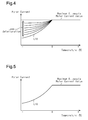
- the warm-up control is performed at a current value that depends on the assumption that the degree of deterioration of the capacitor is the maximum as shown by characteristic line L10 in Fig. 5 .
- the current value of the warm-up control is limited even if deterioration of the capacitor has not progressed, and the warm-up control of the capacitor takes a long time.
- an inverter device includes an inverter circuit having a plurality of switching elements in a bridge connection, a capacitor, which is connected in parallel to an input side of the inverter circuit, a temperature detector, which detects a temperature of the capacitor, a degree-of-deterioration determiner, which determines a degree of deterioration of the capacitor, and a warm-up controller.
- the warm-up controller controls the switching elements of the inverter circuit to supply a direct current set based on the degree of deterioration and the temperature of the capacitor to a coil of an electric motor connected to an output side of the inverter circuit.
- the inverter device is mounted on a forklift and activates a vehicle driving electric motor and a cargo handling electric motor of the forklift.
- the forklift is a battery-operated forklift.
- the forklift is driven by the vehicle driving electric motor and performs cargo handling with the cargo handling electric motor. That is, when an operator operates an accelerator pedal in a state in which the key is turned on, the vehicle driving electric motor is activated to drive the forklift forward or rearward.
- the cargo handling electric motor is activated to lift or lower the fork to handle a cargo.
- Such a forklift may be used in a cold storage in which the ambient temperature is less than or equal to -40°C.
- an inverter (three-phase inverter) 10 includes an inverter circuit 20, a drive circuit 30, and a controller 40.
- the controller 40 functions as a control device for controlling the inverter circuit 20.
- the input side of the inverter circuit 20 is connected to a direct-current power source, which is a battery 50 in the present embodiment, via system relay switches SW1, SW2.
- the output side of the inverter circuit 20 is connected to a vehicle driving electric motor (alternatively, a cargo handling electric motor) 60.
- a three-phase AC motor is used as the motor 60.
- the electric motor 60 includes coils 61, 62, 63 of different phases, which are connected to the output side of the inverter circuit 20.
- the inverter circuit 20 has six switching elements S1 to S6. Each of the switching elements S1 to S6 is a power MOSFET. Insulated-gate bipolar transistors (IGBT) may be used as switching elements. The switching elements S1 to S6 are connected in antiparallel to feedback diodes D1 to D6, respectively.
- IGBT Insulated-gate bipolar transistors
- the first and second switching elements S1 and S2 are connected in series
- the third and fourth switching elements S3 and S4 are connected in series
- the fifth and sixth switching elements S5, S6 are connected in series.
- the first, third, and fifth switching elements S1, S3, S5 are connected to the positive terminal of the direct-current power source, which is the battery 50 in the present embodiment, via the system relay switch SW1.
- the second, fourth, and sixth switching elements S2, S4, S6 are connected to the negative terminal of the battery 50 via the system relay switch SW2.
- the system relay switches SW1, SW2 are closed in response to an ON operation of the key switch and are opened in response to an OFF operation of the key switch.
- the operation signal includes operation signals of the key switch.
- the inverter device 10 supplies alternating currents to the coils of respective phases of the electric motor 60, thereby driving the electric motor 60.
- the inverter circuit 20 has six switching elements S1 to S6 in a bridge connection.
- the rated voltage of the battery 50 is, for example, 48 volts, and the withstand voltage of the switching elements S1 to S6 is approximately 75 volts.
- Current sensors 70, 71 are provided between the inverter circuit 20 and the electric motor 60.
- the current sensors 70, 71 respectively detect the current values of currents Iu and Iw of the U-phase and W-phase, which are two phases of the three-phase currents Iu, Iv, Iw supplied to the electric motor 60.
- An electrolytic capacitor 80 is connected to the input side of the inverter circuit 20 to be parallel with the battery 50.
- the first, third, and fifth switching elements S1, S3, S5 are connected to the positive terminal of the electrolytic capacitor 80, and the second, fourth, and sixth switching elements S2, S4, S6 are connected to the negative terminal of the electrolytic capacitor 80.
- the capacitor can be considered as including, in addition to an ideal capacitor component, a resistance component R and an inductor component L.
- the electrolytic capacitor 80 is equivalently represented by an ideal capacitor C and the resistance component R, which are connected in series.
- the resistance component R is an equivalent series resistance (ESR) of the capacitor.
- the input side of the inverter circuit 20 is connected to the battery 50, which serves as a direct-current power source, and the electrolytic capacitor 80, which are connected in parallel.
- the inverter device 10 further includes a capacitor temperature sensor 90, which detects the temperature of the electrolytic capacitor 80.
- the capacitor temperature sensor 90 which functions as a temperature detector, is connected to the controller 40, so that the controller 40 detects the temperature of the electrolytic capacitor 80 (capacitor temperature).
- the inverter device 10 When controlling the electric motor 60 to perform normal operation under a low-temperature environment, the inverter device 10 functions to limit the currents output to the electric motor 60 to protect the electric motor 60 and components of the inverter device 10. For example, when the temperature of the electrolytic capacitor 80 (capacitor temperature) drops, for example, to or below -20°C, the output currents to the electric motor 60 are limited.
- the inverter device 10 includes a power supply circuit 45.
- the power supply circuit 45 is connected to the battery 50 via the system relay switches SW1, SW2.
- the power supply circuit 45 receives a voltage from the battery 50 and steps down the voltage to a predetermined voltage (for example, 15 volts) before supplying the voltage to the controller 40.
- the controller 40 includes a microcomputer 41 and a memory 42.
- the microcomputer 41 operates upon receipt of the voltage (for example, 15 volts) from the power supply circuit 45.
- the memory 42 stores various control programs necessary for driving the electric motor 60 and various data and maps for executing the control programs.
- the control program includes a normal control program for drivingly rotating the electric motor (motor) 60 and a control program for supplying a direct current to the electric motor 60 for warm-up control when the ambient temperature is low.
- the memory 42 also stores the map shown in Fig. 2 .
- the horizontal axis represents the temperature of the electrolytic capacitor 80
- the vertical axis represents the maximum current value supplied during warm-up.
- Fig. 2 shows characteristic lines L1, L2, ....
- the characteristic lines L1, L2, ... linearly extend from the point P1 diagonally upward and rightward.
- the map is used to obtain the maximum current value supplied during warm-up based on the temperature of the electrolytic capacitor 80 and the degree of deterioration of the electrolytic capacitor 80.
- the controller 40 is connected to the gates of the switching elements S1 to S6 via the drive circuit 30.
- the current sensors 70, 71 are connected to the controller 40. Based on detection signals from the sensors 70, 71, the controller 40 outputs control signals to the switching elements S1 to S6 via the drive circuit 30 such that the electric motor 60 generates power to a target level.
- the inverter circuit 20 converts the direct current from the battery 50 and the electrolytic capacitor 80 into alternating currents of three phases having an appropriate frequency and outputs the alternating currents to the electric motor 60.
- the vehicle has a vehicle-controlling electronic control unit (ECU) 120.
- the vehicle-controlling ECU 120 receives operation signals from operation sensors (not shown) manipulated by the operator and controls the movement of the vehicle, accordingly.
- the controller 40 is connected to the vehicle-controlling ECU 120 and detects manipulation of the key switch.
- the controller 40, the drive circuit 30, and the power supply circuit 45 of the inverter 10 are mounted on a control board 110.
- the microcomputer 41 sums a closed circuit time of the system relay switches SW1, SW2 (the ON time of the key switch) and stores the result as an integrated inverter ON time in the memory 42.
- the integrated inverter ON time is an integrated connection time of the battery 50 to the electrolytic capacitor 80. That is, the connection time is the sum total of the time during which the electrolytic capacitor 80 is electrically connected to the battery 50.
- the microcomputer 41 also sums an activation time (power running time and regeneration time) of the electric motor 60 by the inverter device 10 and stores the result as an integrated motor activation time in the memory 42.
- the integrated motor activation time is the integrated activation time of the inverter device 10. That is, the activation time is the sum total of the time during which the inverter device 10 is activated.
- Deterioration of the electrolytic capacitor 80 is known to progress by long-term use even at ordinary temperatures, causing the internal resistance of the electrolytic capacitor 80 to gradually increase.
- the internal resistance of the electrolytic capacitor 80 is increased by an amount corresponding to the decrease in the temperature in addition to the internal resistance at ordinary temperatures.
- the warm-up control is conventionally performed based on a case in which the degree of deterioration of the electrolytic capacitor is the maximum as shown by characteristic line L10 in Fig. 5 .
- Such a control requires a long time for the warm-up control even if deterioration of the electrolytic capacitor has not progressed.
- the amount of current to be supplied is determined in accordance with the degree of deterioration as follows.
- the microcomputer 41 receives the temperature of the electrolytic capacitor 80 detected by the capacitor temperature sensor 90 in step 100 and determines whether the temperature is less than or equal to -20°C in step 101. If the temperature of the electrolytic capacitor 80 is higher than -20°C, the microcomputer 41 proceeds to step 102 and performs normal operation control.
- step 101 if the temperature of the electrolytic capacitor 80 is less than or equal to-20°C, the microcomputer 41 sets a warm-up mode.
- step 103 the microcomputer 41 in the warm-up mode calculates the degree of deterioration of the electrolytic capacitor 80 (degree of capacitor deterioration) based on the integrated inverter ON time and the integrated motor activation time. The longer at least one of the integrated inverter ON time and the integrated motor activation time, the greater the degree of deterioration of the electrolytic capacitor 80 is set to.
- step 104 the microcomputer 41 calculates the maximum current value based on the degree of capacitor deterioration and the temperature of the electrolytic capacitor 80 detected by the capacitor temperature sensor 90 using the map of Fig. 2 .
- the microcomputer 41 calculates the maximum current value corresponding to the degree of deterioration of the electrolytic capacitor 80. More specifically, if deterioration of the electrolytic capacitor 80 has not progressed, the maximum current value is set to a great value, and if deterioration of the electrolytic capacitor 80 has progressed, the maximum current value is set to a small value.
- step 105 if the temperature of the electrolytic capacitor 80 is less than or equal to-20°C, the microcomputer 41 proceeds to step 106.
- step 106 the microcomputer 41 controls the switching elements S1 to S6 of the inverter circuit 20 to supply an electric current to the electrolytic capacitor 80 at the calculated maximum current value via the coils of respective phases of the electric motor 60. That is, the warm-up control is performed in which a direct current is supplied.
- step 105 if the temperature of the electrolytic capacitor 80 exceeds -20°C, the microcomputer 41 proceeds to step 102 and performs the normal operation control.
- the inverter device 10 supplies direct currents to the electric motor 60 to increase the temperature of the electrolytic capacitor 80.
- a prescribed value for example, -20°C
- the normal operation control is performed. In other words, the inverter device 10 supplies alternating currents to the electric motor 60.
- the horizontal axis represents the temperature of the electrolytic capacitor 80, and the vertical axis represents the maximum current value.
- the time required for the temperature of the electrolytic capacitor 80 to increase to a predetermined temperature depends on the maximum current value.
- the maximum current value (L10) is determined while factoring in the increase in the internal resistance due to deterioration of the electrolytic capacitor 80.
- the time required for the temperature of the electrolytic capacitor 80 to increase to the predetermined temperature is longer than the time required in a case in which the maximum current value (L10) is determined based on the internal resistance before the deterioration.
- the maximum current value is specified depending on the degree of deterioration of the electrolytic capacitor 80. That is, the lower the degree of deterioration of the electrolytic capacitor 80, the greater the maximum current value of current supplied to the electrolytic capacitor 80 is set to. Thus, if deterioration of the electrolytic capacitor 80 has not progressed, the maximum current value is increased to quickly end the warm-up control.
- the internal controller 40 of the inverter device 10 calculates the integrated inverter ON time and the integrated motor activation time.
- the degree of capacitor deterioration is estimated considering that the deterioration of the electrolytic capacitor 80 is caused by temperature increase that occurs when electric current are supplied to the electrolytic capacitor 80 for charging when the system relay switches SW1, SW2 are on and also by heat when electric current are supplied to the electrolytic capacitor 80 during regeneration and power running.
- the maximum current value is determined in accordance with the degree of deterioration and the temperature of the electrolytic capacitor 80 to complete the warm-up operation at an early stage.
- the present embodiment is not limited to the above configuration, but may be modified as follows.
- the integrated connection time of the battery 50 to the capacitor, which is the integrated inverter ON time, and the integrated activation time of the inverter, which is the integrated motor activation time, are measured by the controller 40 inside the inverter device 10, but may be measured outside the inverter device 10. More specifically, the above measurements may be performed in a different ECU, for example, the vehicle-controlling ECU 120. That is, the inverter device may include the vehicle-controlling ECU 120.
- the capacitor temperature sensor 90 which directly detects the temperature of the electrolytic capacitor 80, is used. However, the temperature of the electrolytic capacitor 80 does not necessarily have to be directly detected, but the temperature of the electrolytic capacitor 80 may be indirectly detected, or estimated. For example, the temperature of the electrolytic capacitor 80 may be detected, or estimated, by measuring the temperature of the control board 110.
Landscapes
- Engineering & Computer Science (AREA)
- Power Engineering (AREA)
- Transportation (AREA)
- Mechanical Engineering (AREA)
- Life Sciences & Earth Sciences (AREA)
- Sustainable Development (AREA)
- Sustainable Energy (AREA)
- Inverter Devices (AREA)
- Electric Propulsion And Braking For Vehicles (AREA)
- Control Of Electric Motors In General (AREA)
- Control Of Ac Motors In General (AREA)
Abstract
Description
- The present invention relates to an inverter device.
- Inverter devices that drive an electric motor include a capacitor as a component. The internal resistance of the capacitor increases under a low-temperature environment. If a great input is applied to such an inverter device from the electric motor during, for example, regenerating operation, an internal voltage is increased and internal elements of the inverter device may be destroyed. To avoid such a situation, the temperature of the capacitor needs to be quickly increased to reduce the capacitor internal resistance. For this reason, warm-up control is performed in which, during a startup, an electric current is applied for a few seconds without the electric motor being rotated, and thus generated heat is used to increase the temperature of the capacitor.
- For example,
Patent Document 1 discloses a method for controlling an electric motor that increases the temperature of a capacitor of an inverter device at a low ambient temperature. Specifically, depending on the ambient temperature of the inverter device, a ripple voltage is generated by the equivalent series resistance of the capacitor. The maximum allowable motor current value at which the components of the inverter device are not damaged by the ripple voltage is set using a map or a relational expression representing a relationship between the maximum value of the motor current and the temperature. If the maximum allowable motor current value set based on the temperature of the capacitor is lower than a value capable of generating torque required for starting the electric motor, the angular position of the rotor of the electric motor is estimated and a direct current lower than or equal to the maximum allowable motor current value is supplied as a d-axis current to increase the temperature of the capacitor of the inverter device. After the maximum allowable motor current value set based on the temperature of the capacitor reaches and exceeds a value capable of generating the torque required for starting the electric motor, the inverter device is controlled to supply alternating currents to the electric motor. - Patent Document 1: Japanese Laid-Open Patent Publication No.
2009-60776 - To promptly increase the capacitor temperature, a great current may be supplied during the warm-up control. However, if a great current is supplied to the inverter device under a low-temperature environment as the warm-up control, the voltage drop amount is undesirably increased since the internal resistance of the capacitor is increased. If the voltage drop amount is great, the system becomes unstable, and the microcomputer of the inverter device may be reset. The internal resistance of the capacitor increases even at ordinary temperatures due to progress of deterioration by long-term use. Furthermore, in a case in which the capacitor is used under a low-temperature environment, in addition to the internal resistance at the ordinary temperatures, the internal resistance of the capacitor is increased by an amount corresponding to the decrease in the temperature. Conventionally, the warm-up control is performed at a current value that depends on the assumption that the degree of deterioration of the capacitor is the maximum as shown by characteristic line L10 in
Fig. 5 . When such a control is performed, the current value of the warm-up control is limited even if deterioration of the capacitor has not progressed, and the warm-up control of the capacitor takes a long time. - Accordingly, it is an objective of the present invention to provide an inverter device that promptly completes warm-up of a capacitor at a low ambient temperature. Means for Solving the Problems
- To achieve the foregoing objective and in accordance with one aspect of the present invention, an inverter device is provided that includes an inverter circuit having a plurality of switching elements in a bridge connection, a capacitor, which is connected in parallel to an input side of the inverter circuit, a temperature detector, which detects a temperature of the capacitor, a degree-of-deterioration determiner, which determines a degree of deterioration of the capacitor, and a warm-up controller. When the temperature of the capacitor detected by the temperature detector is lower than a prescribed temperature, the warm-up controller controls the switching elements of the inverter circuit to supply a direct current set based on the degree of deterioration and the temperature of the capacitor to a coil of an electric motor connected to an output side of the inverter circuit.
-
-
Fig. 1 is a circuit diagram of an inverter device according to one embodiment; -
Fig. 2 is an explanatory diagram of a map stored in a memory; -
Fig. 3 is a flowchart for describing operation of the inverter device; -
Fig. 4 is an explanatory diagram of the maximum current value; and -
Fig. 5 is an explanatory diagram of the maximum current value for describing an issue of a conventional inverter device. - An inverter device according to one embodiment of the present invention will now be described with reference to the drawings. The inverter device is mounted on a forklift and activates a vehicle driving electric motor and a cargo handling electric motor of the forklift. The forklift is a battery-operated forklift. The forklift is driven by the vehicle driving electric motor and performs cargo handling with the cargo handling electric motor. That is, when an operator operates an accelerator pedal in a state in which the key is turned on, the vehicle driving electric motor is activated to drive the forklift forward or rearward. When the operator manipulates the lift lever, the cargo handling electric motor is activated to lift or lower the fork to handle a cargo. Such a forklift may be used in a cold storage in which the ambient temperature is less than or equal to -40°C.
- As shown in
Fig. 1 , an inverter (three-phase inverter) 10 includes aninverter circuit 20, adrive circuit 30, and acontroller 40. Thecontroller 40 functions as a control device for controlling theinverter circuit 20. The input side of theinverter circuit 20 is connected to a direct-current power source, which is abattery 50 in the present embodiment, via system relay switches SW1, SW2. - The output side of the
inverter circuit 20 is connected to a vehicle driving electric motor (alternatively, a cargo handling electric motor) 60. A three-phase AC motor is used as themotor 60. Theelectric motor 60 includescoils inverter circuit 20. - The
inverter circuit 20 has six switching elements S1 to S6. Each of the switching elements S1 to S6 is a power MOSFET. Insulated-gate bipolar transistors (IGBT) may be used as switching elements. The switching elements S1 to S6 are connected in antiparallel to feedback diodes D1 to D6, respectively. - In the
inverter circuit 20, the first and second switching elements S1 and S2 are connected in series, the third and fourth switching elements S3 and S4 are connected in series, and the fifth and sixth switching elements S5, S6 are connected in series. The first, third, and fifth switching elements S1, S3, S5 are connected to the positive terminal of the direct-current power source, which is thebattery 50 in the present embodiment, via the system relay switch SW1. The second, fourth, and sixth switching elements S2, S4, S6 are connected to the negative terminal of thebattery 50 via the system relay switch SW2. - The system relay switches SW1, SW2 are closed in response to an ON operation of the key switch and are opened in response to an OFF operation of the key switch. In
Fig. 1 , the operation signal includes operation signals of the key switch. - A connecting point between the switching elements S1 and S2, which form upper and lower arms for the U-phase, is connected to the U-phase terminal of the
electric motor 60. A connecting point between the switching elements S3 and S4, which form upper and lower arms for the V-phase, is connected to the V-phase terminal of theelectric motor 60. A connecting point between the switching elements S5 and S6, which form upper and lower arms for the W-phase, is connected to the W-phase terminal of theelectric motor 60. Theinverter device 10 supplies alternating currents to the coils of respective phases of theelectric motor 60, thereby driving theelectric motor 60. As described above, theinverter circuit 20 has six switching elements S1 to S6 in a bridge connection. - The rated voltage of the
battery 50 is, for example, 48 volts, and the withstand voltage of the switching elements S1 to S6 is approximately 75 volts. -
Current sensors 70, 71 are provided between theinverter circuit 20 and theelectric motor 60. Thecurrent sensors 70, 71 respectively detect the current values of currents Iu and Iw of the U-phase and W-phase, which are two phases of the three-phase currents Iu, Iv, Iw supplied to theelectric motor 60. - An
electrolytic capacitor 80 is connected to the input side of theinverter circuit 20 to be parallel with thebattery 50. The first, third, and fifth switching elements S1, S3, S5 are connected to the positive terminal of theelectrolytic capacitor 80, and the second, fourth, and sixth switching elements S2, S4, S6 are connected to the negative terminal of theelectrolytic capacitor 80. In general, if a capacitor is regarded as an equivalent circuit, the capacitor can be considered as including, in addition to an ideal capacitor component, a resistance component R and an inductor component L. InFig. 1 , theelectrolytic capacitor 80 is equivalently represented by an ideal capacitor C and the resistance component R, which are connected in series. The resistance component R is an equivalent series resistance (ESR) of the capacitor. - As described above, the input side of the
inverter circuit 20 is connected to thebattery 50, which serves as a direct-current power source, and theelectrolytic capacitor 80, which are connected in parallel. - The
inverter device 10 further includes acapacitor temperature sensor 90, which detects the temperature of theelectrolytic capacitor 80. Thecapacitor temperature sensor 90, which functions as a temperature detector, is connected to thecontroller 40, so that thecontroller 40 detects the temperature of the electrolytic capacitor 80 (capacitor temperature). When controlling theelectric motor 60 to perform normal operation under a low-temperature environment, theinverter device 10 functions to limit the currents output to theelectric motor 60 to protect theelectric motor 60 and components of theinverter device 10. For example, when the temperature of the electrolytic capacitor 80 (capacitor temperature) drops, for example, to or below -20°C, the output currents to theelectric motor 60 are limited. - The
inverter device 10 includes apower supply circuit 45. Thepower supply circuit 45 is connected to thebattery 50 via the system relay switches SW1, SW2. Thepower supply circuit 45 receives a voltage from thebattery 50 and steps down the voltage to a predetermined voltage (for example, 15 volts) before supplying the voltage to thecontroller 40. Thecontroller 40 includes amicrocomputer 41 and amemory 42. Themicrocomputer 41 operates upon receipt of the voltage (for example, 15 volts) from thepower supply circuit 45. - The
memory 42 stores various control programs necessary for driving theelectric motor 60 and various data and maps for executing the control programs. The control program includes a normal control program for drivingly rotating the electric motor (motor) 60 and a control program for supplying a direct current to theelectric motor 60 for warm-up control when the ambient temperature is low. - The
memory 42 also stores the map shown inFig. 2 . InFig. 2 , the horizontal axis represents the temperature of theelectrolytic capacitor 80, and the vertical axis represents the maximum current value supplied during warm-up.Fig. 2 shows characteristic lines L1, L2, .... The characteristic lines L1, L2, ... linearly extend from the point P1 diagonally upward and rightward. In the map, the greater the degree of deterioration of theelectrolytic capacitor 80, the smaller the inclination becomes. The map is used to obtain the maximum current value supplied during warm-up based on the temperature of theelectrolytic capacitor 80 and the degree of deterioration of theelectrolytic capacitor 80. - The
controller 40 is connected to the gates of the switching elements S1 to S6 via thedrive circuit 30. Thecurrent sensors 70, 71 are connected to thecontroller 40. Based on detection signals from thesensors 70, 71, thecontroller 40 outputs control signals to the switching elements S1 to S6 via thedrive circuit 30 such that theelectric motor 60 generates power to a target level. Theinverter circuit 20 converts the direct current from thebattery 50 and theelectrolytic capacitor 80 into alternating currents of three phases having an appropriate frequency and outputs the alternating currents to theelectric motor 60. - The vehicle has a vehicle-controlling electronic control unit (ECU) 120. The vehicle-controlling
ECU 120 receives operation signals from operation sensors (not shown) manipulated by the operator and controls the movement of the vehicle, accordingly. Thecontroller 40 is connected to the vehicle-controllingECU 120 and detects manipulation of the key switch. Thecontroller 40, thedrive circuit 30, and thepower supply circuit 45 of theinverter 10 are mounted on acontrol board 110. - The
microcomputer 41 sums a closed circuit time of the system relay switches SW1, SW2 (the ON time of the key switch) and stores the result as an integrated inverter ON time in thememory 42. The integrated inverter ON time is an integrated connection time of thebattery 50 to theelectrolytic capacitor 80. That is, the connection time is the sum total of the time during which theelectrolytic capacitor 80 is electrically connected to thebattery 50. - The
microcomputer 41 also sums an activation time (power running time and regeneration time) of theelectric motor 60 by theinverter device 10 and stores the result as an integrated motor activation time in thememory 42. The integrated motor activation time is the integrated activation time of theinverter device 10. That is, the activation time is the sum total of the time during which theinverter device 10 is activated. - Operation of the
inverter device 10 will now be described. - Deterioration of the
electrolytic capacitor 80 is known to progress by long-term use even at ordinary temperatures, causing the internal resistance of theelectrolytic capacitor 80 to gradually increase. When theelectrolytic capacitor 80 is used under a low-temperature environment, the internal resistance of theelectrolytic capacitor 80 is increased by an amount corresponding to the decrease in the temperature in addition to the internal resistance at ordinary temperatures. Thus, the warm-up control is conventionally performed based on a case in which the degree of deterioration of the electrolytic capacitor is the maximum as shown by characteristic line L10 inFig. 5 . Such a control, however, requires a long time for the warm-up control even if deterioration of the electrolytic capacitor has not progressed. - In the present embodiment, the amount of current to be supplied is determined in accordance with the degree of deterioration as follows.
- As shown in
Fig. 3 , when the key switch is turned on, themicrocomputer 41 receives the temperature of theelectrolytic capacitor 80 detected by thecapacitor temperature sensor 90 instep 100 and determines whether the temperature is less than or equal to -20°C instep 101. If the temperature of theelectrolytic capacitor 80 is higher than -20°C, themicrocomputer 41 proceeds to step 102 and performs normal operation control. - In
step 101, if the temperature of theelectrolytic capacitor 80 is less than or equal to-20°C, themicrocomputer 41 sets a warm-up mode. Instep 103, themicrocomputer 41 in the warm-up mode calculates the degree of deterioration of the electrolytic capacitor 80 (degree of capacitor deterioration) based on the integrated inverter ON time and the integrated motor activation time. The longer at least one of the integrated inverter ON time and the integrated motor activation time, the greater the degree of deterioration of theelectrolytic capacitor 80 is set to. Instep 104, themicrocomputer 41 calculates the maximum current value based on the degree of capacitor deterioration and the temperature of theelectrolytic capacitor 80 detected by thecapacitor temperature sensor 90 using the map ofFig. 2 . That is, themicrocomputer 41 calculates the maximum current value corresponding to the degree of deterioration of theelectrolytic capacitor 80. More specifically, if deterioration of theelectrolytic capacitor 80 has not progressed, the maximum current value is set to a great value, and if deterioration of theelectrolytic capacitor 80 has progressed, the maximum current value is set to a small value. - In
step 105, if the temperature of theelectrolytic capacitor 80 is less than or equal to-20°C, themicrocomputer 41 proceeds to step 106. Instep 106, themicrocomputer 41 controls the switching elements S1 to S6 of theinverter circuit 20 to supply an electric current to theelectrolytic capacitor 80 at the calculated maximum current value via the coils of respective phases of theelectric motor 60. That is, the warm-up control is performed in which a direct current is supplied. - In
step 105, if the temperature of theelectrolytic capacitor 80 exceeds -20°C, themicrocomputer 41 proceeds to step 102 and performs the normal operation control. - As described above, if the temperature of the
electrolytic capacitor 80 is extremely low (for example, approximately -40°C), theinverter device 10 supplies direct currents to theelectric motor 60 to increase the temperature of theelectrolytic capacitor 80. When the temperature of theelectrolytic capacitor 80 reaches a prescribed value (for example, -20°C), that is, the temperature at which theelectric motor 60 can be started, the normal operation control is performed. In other words, theinverter device 10 supplies alternating currents to theelectric motor 60. - The maximum current value will be described using
Fig. 4 . - In
Fig. 4 , the horizontal axis represents the temperature of theelectrolytic capacitor 80, and the vertical axis represents the maximum current value. - As shown by characteristic line L10 in
Fig. 5 (also shown one above the other inFig. 4 ), the time required for the temperature of theelectrolytic capacitor 80 to increase to a predetermined temperature (0°C inFig. 5 ) depends on the maximum current value. In the conventional inverter device, the maximum current value (L10) is determined while factoring in the increase in the internal resistance due to deterioration of theelectrolytic capacitor 80. Thus, the time required for the temperature of theelectrolytic capacitor 80 to increase to the predetermined temperature is longer than the time required in a case in which the maximum current value (L10) is determined based on the internal resistance before the deterioration. - In
Fig. 4 of the present embodiment, the maximum current value is specified depending on the degree of deterioration of theelectrolytic capacitor 80. That is, the lower the degree of deterioration of theelectrolytic capacitor 80, the greater the maximum current value of current supplied to theelectrolytic capacitor 80 is set to. Thus, if deterioration of theelectrolytic capacitor 80 has not progressed, the maximum current value is increased to quickly end the warm-up control. - More specifically, the
internal controller 40 of theinverter device 10 calculates the integrated inverter ON time and the integrated motor activation time. The degree of capacitor deterioration is estimated considering that the deterioration of theelectrolytic capacitor 80 is caused by temperature increase that occurs when electric current are supplied to theelectrolytic capacitor 80 for charging when the system relay switches SW1, SW2 are on and also by heat when electric current are supplied to theelectrolytic capacitor 80 during regeneration and power running. The maximum current value is determined in accordance with the degree of deterioration and the temperature of theelectrolytic capacitor 80 to complete the warm-up operation at an early stage. - The above described embodiment has the following advantages.
-
- (1) The
inverter device 10 includes thecapacitor temperature sensor 90 and themicrocomputer 41, which serves as the degree-of-deterioration determiner and the warm-up controller. Themicrocomputer 41 determines the degree of deterioration of theelectrolytic capacitor 80. If the temperature of theelectrolytic capacitor 80 detected by thecapacitor temperature sensor 90 is less than the prescribed temperature, themicrocomputer 41 controls the switching elements S1 to S6 of theinverter circuit 20 to supply direct currents that are set based on the degree of deterioration of theelectrolytic capacitor 80 and the capacitor temperature to the coils of theelectric motor 60. Thus, when the ambient temperature is low, warm-up of theelectrolytic capacitor 80 is promptly completed.
That is, under a low-temperature environment, since the internal resistance of the capacitor is greater than that at ordinary temperatures, the degree of decrease in the voltage when supplying a warm-up current to the elements is increased. In general, deterioration of an electrolytic capacitor progresses in accordance with the time of use, and the internal resistance increases in accordance with the degree of deterioration. The degree of voltage drop when supplying a warm-up current to the elements is also increased in accordance with the deterioration. When the decreased voltage value becomes less than a designed value of the control board, the microcomputer mounted on the control board is reset so that the warm-up control is interrupted. To avoid such a situation, conventionally, a warm-up current that can be supplied to the elements at each ambient temperature is limited based on the maximum degree of deterioration of the capacitor. However, the method requires a long time for the capacitor to be heated to the predetermined temperature and fails to meet the needs for operating at an early stage.
In contrast, in the present embodiment, since the switching elements S1 to S6 of theinverter circuit 20 are controlled to supply the optimal direct current set based on the degree of deterioration of theelectrolytic capacitor 80 to the coils of the electric motor, the warm-up of theelectrolytic capacitor 80 is promptly completed at a low ambient temperature. - (2) The
microcomputer 41, which serves as the degree-of-deterioration determiner, determines the degree of deterioration of theelectrolytic capacitor 80 based on the connection time, which is the sum total of the time during which theelectrolytic capacitor 80 is electrically connected to the direct-current power source, or thebattery 50, and the activation time, which is the sum total of the time during which theinverter device 10 is activated. Thus, the degree of deterioration is more accurately calculated. - (3) The lower the temperature of the
electrolytic capacitor 80 is, the lower the current value of the direct current is set. This is more preferable than the conventional inverter device. - The present embodiment is not limited to the above configuration, but may be modified as follows.
- The integrated connection time of the
battery 50 to the capacitor, which is the integrated inverter ON time, and the integrated activation time of the inverter, which is the integrated motor activation time, are measured by thecontroller 40 inside theinverter device 10, but may be measured outside theinverter device 10. More specifically, the above measurements may be performed in a different ECU, for example, the vehicle-controllingECU 120. That is, the inverter device may include the vehicle-controllingECU 120. - The
capacitor temperature sensor 90, which directly detects the temperature of theelectrolytic capacitor 80, is used. However, the temperature of theelectrolytic capacitor 80 does not necessarily have to be directly detected, but the temperature of theelectrolytic capacitor 80 may be indirectly detected, or estimated. For example, the temperature of theelectrolytic capacitor 80 may be detected, or estimated, by measuring the temperature of thecontrol board 110.
Claims (5)
- An inverter device comprising:an inverter circuit having a plurality of switching elements in a bridge connection;a capacitor, which is connected in parallel to an input side of the inverter circuit;a temperature detector, which detects a temperature of the capacitor;a degree-of-deterioration determiner, which determines a degree of deterioration of the capacitor; anda warm-up controller, wherein, when the temperature of the capacitor detected by the temperature detector is lower than a prescribed temperature, the warm-up controller controls the switching elements of the inverter circuit to supply a direct current set based on the degree of deterioration and the temperature of the capacitor to a coil of an electric motor connected to an output side of the inverter circuit.
- The inverter device according to claim 1, wherein the degree-of-deterioration determiner determines the degree of deterioration of the capacitor based on a connection time, which is the sum total of time during which the capacitor is electrically connected to a direct-current power source connected to the input side of the inverter circuit, and an activation time, which is the sum total of time during which the inverter is activated.
- The inverter device according to claim 2, wherein the longer at least one of the connection time and the activation time, the greater the degree of deterioration of the capacitor is set to.
- The inverter device according to any one of claims 1 to 4, wherein the lower the temperature of the capacitor, the lower the current value of the direct current is set to.
- The inverter device according to any one of claims 1 to 4, wherein the greater the degree of deterioration of the capacitor, the lower the current value of the direct current is set to.
Applications Claiming Priority (2)
| Application Number | Priority Date | Filing Date | Title |
|---|---|---|---|
| JP2012257686A JP6075029B2 (en) | 2012-11-26 | 2012-11-26 | Inverter warm-up control device |
| PCT/JP2013/079681 WO2014080740A1 (en) | 2012-11-26 | 2013-11-01 | Inverter device |
Publications (2)
| Publication Number | Publication Date |
|---|---|
| EP2924876A1 true EP2924876A1 (en) | 2015-09-30 |
| EP2924876A4 EP2924876A4 (en) | 2016-07-27 |
Family
ID=50775926
Family Applications (1)
| Application Number | Title | Priority Date | Filing Date |
|---|---|---|---|
| EP13856547.8A Withdrawn EP2924876A4 (en) | 2012-11-26 | 2013-11-01 | Inverter device |
Country Status (4)
| Country | Link |
|---|---|
| US (1) | US9577510B2 (en) |
| EP (1) | EP2924876A4 (en) |
| JP (1) | JP6075029B2 (en) |
| WO (1) | WO2014080740A1 (en) |
Cited By (1)
| Publication number | Priority date | Publication date | Assignee | Title |
|---|---|---|---|---|
| US20150295514A1 (en) * | 2012-11-26 | 2015-10-15 | Kabushiki Kaisha Toyota Jidoshokki | Inverter device |
Families Citing this family (7)
| Publication number | Priority date | Publication date | Assignee | Title |
|---|---|---|---|---|
| CN107408896B (en) * | 2015-02-26 | 2020-01-03 | 株式会社日立产机系统 | Power conversion device and control method thereof |
| JP6529459B2 (en) * | 2016-04-06 | 2019-06-12 | 日立オートモティブシステムズ株式会社 | Motor drive device and electric power steering apparatus using the same |
| WO2017212585A1 (en) * | 2016-06-08 | 2017-12-14 | 三菱電機株式会社 | Motor control device |
| JP6759830B2 (en) * | 2016-08-08 | 2020-09-23 | 富士電機株式会社 | Power converter |
| US10737575B2 (en) * | 2017-11-22 | 2020-08-11 | Ford Global Technologies, Llc | Power device parameter adjustment |
| JP7300307B2 (en) | 2019-05-07 | 2023-06-29 | サンデン株式会社 | Inverter device |
| KR20210076728A (en) * | 2019-12-16 | 2021-06-24 | 현대자동차주식회사 | System and method for protecting dc capacitor of inverter from overtemperature |
Family Cites Families (16)
| Publication number | Priority date | Publication date | Assignee | Title |
|---|---|---|---|---|
| JP2002165357A (en) * | 2000-11-27 | 2002-06-07 | Canon Inc | Power converter and its control method, and power generating system |
| JP4270155B2 (en) * | 2005-04-08 | 2009-05-27 | トヨタ自動車株式会社 | Exhaust purification catalyst thermal degradation state detection device |
| JP4797488B2 (en) * | 2005-07-26 | 2011-10-19 | パナソニック株式会社 | Vehicle power supply |
| JP2007049837A (en) * | 2005-08-10 | 2007-02-22 | Hitachi Ltd | Controller for power converter |
| CN101495876B (en) * | 2006-07-31 | 2012-11-14 | 三菱电机株式会社 | Power supply device and sequencer system |
| JP5011940B2 (en) * | 2006-10-16 | 2012-08-29 | トヨタ自動車株式会社 | Power supply device and vehicle |
| JP5217579B2 (en) * | 2007-08-06 | 2013-06-19 | 株式会社豊田自動織機 | Electric motor control method and control apparatus |
| EP2028759B1 (en) * | 2007-08-06 | 2014-12-17 | Kabushiki Kaisha Toyota Jidoshokki | Method and apparatus for controlling electric motor |
| JP5018448B2 (en) * | 2007-12-18 | 2012-09-05 | パナソニック株式会社 | Power storage device |
| JP5277711B2 (en) * | 2008-05-09 | 2013-08-28 | 新神戸電機株式会社 | Power supply device and vehicle power supply device |
| WO2010087363A1 (en) * | 2009-01-28 | 2010-08-05 | 住友重機械工業株式会社 | Hybrid working machine and electricity storage control apparatus |
| JP4873106B2 (en) * | 2009-06-30 | 2012-02-08 | パナソニック株式会社 | Power supply |
| JP5104892B2 (en) * | 2010-03-09 | 2012-12-19 | オムロン株式会社 | Switching power supply |
| JP5925425B2 (en) * | 2011-04-07 | 2016-05-25 | サンデンホールディングス株式会社 | Inverter device |
| JP5829652B2 (en) * | 2013-07-02 | 2015-12-09 | 本田技研工業株式会社 | Vehicle power supply |
| JP2015009791A (en) * | 2013-07-02 | 2015-01-19 | 本田技研工業株式会社 | Vehicle power supply device |
-
2012
- 2012-11-26 JP JP2012257686A patent/JP6075029B2/en active Active
-
2013
- 2013-11-01 US US14/443,861 patent/US9577510B2/en not_active Expired - Fee Related
- 2013-11-01 EP EP13856547.8A patent/EP2924876A4/en not_active Withdrawn
- 2013-11-01 WO PCT/JP2013/079681 patent/WO2014080740A1/en active Application Filing
Cited By (2)
| Publication number | Priority date | Publication date | Assignee | Title |
|---|---|---|---|---|
| US20150295514A1 (en) * | 2012-11-26 | 2015-10-15 | Kabushiki Kaisha Toyota Jidoshokki | Inverter device |
| US9467068B2 (en) * | 2012-11-26 | 2016-10-11 | Kabushiki Kaisha Toyota Jidoshokki | Inverter device |
Also Published As
| Publication number | Publication date |
|---|---|
| JP2014107897A (en) | 2014-06-09 |
| US9577510B2 (en) | 2017-02-21 |
| US20150295490A1 (en) | 2015-10-15 |
| EP2924876A4 (en) | 2016-07-27 |
| JP6075029B2 (en) | 2017-02-08 |
| WO2014080740A1 (en) | 2014-05-30 |
Similar Documents
| Publication | Publication Date | Title |
|---|---|---|
| US9577510B2 (en) | Inverter device | |
| US9048771B2 (en) | Inverter | |
| EP2028759B1 (en) | Method and apparatus for controlling electric motor | |
| JP5217579B2 (en) | Electric motor control method and control apparatus | |
| US9467068B2 (en) | Inverter device | |
| JP4609474B2 (en) | Rotating electrical machine equipment | |
| US8054031B2 (en) | Converter device, rotating electrical machine control device, and drive device | |
| US9496802B2 (en) | Inverter device | |
| US10348238B2 (en) | Drive system | |
| JP6863046B2 (en) | Automobile | |
| JP2019009940A (en) | Inverter | |
| JP2008136327A (en) | Method and device for controlling motor | |
| US8851218B2 (en) | Method for determining a power limiting value for an electric machine in a vehicle, computer program and control unit for controlling an electric machine in a vehicle | |
| JP2010166715A (en) | Controller and control system for rotating machine | |
| JP6708843B2 (en) | Drive | |
| JP6020160B2 (en) | Inverter warm-up control device | |
| JP2009274777A (en) | Cargo-handling regeneration device of forklift | |
| JP6935739B2 (en) | Boost system |
Legal Events
| Date | Code | Title | Description |
|---|---|---|---|
| PUAI | Public reference made under article 153(3) epc to a published international application that has entered the european phase |
Free format text: ORIGINAL CODE: 0009012 |
|
| 17P | Request for examination filed |
Effective date: 20150504 |
|
| AK | Designated contracting states |
Kind code of ref document: A1 Designated state(s): AL AT BE BG CH CY CZ DE DK EE ES FI FR GB GR HR HU IE IS IT LI LT LU LV MC MK MT NL NO PL PT RO RS SE SI SK SM TR |
|
| AX | Request for extension of the european patent |
Extension state: BA ME |
|
| DAX | Request for extension of the european patent (deleted) | ||
| RA4 | Supplementary search report drawn up and despatched (corrected) |
Effective date: 20160624 |
|
| RIC1 | Information provided on ipc code assigned before grant |
Ipc: B60L 3/00 20060101ALI20160617BHEP Ipc: H02M 7/5387 20070101ALN20160617BHEP Ipc: H02P 27/06 20060101AFI20160617BHEP Ipc: H02M 7/5375 20060101ALI20160617BHEP Ipc: B60L 15/00 20060101ALI20160617BHEP Ipc: H02M 1/36 20070101ALI20160617BHEP Ipc: H02M 1/32 20070101ALI20160617BHEP Ipc: H02M 7/48 20070101ALI20160617BHEP |
|
| STAA | Information on the status of an ep patent application or granted ep patent |
Free format text: STATUS: THE APPLICATION HAS BEEN WITHDRAWN |
|
| 18W | Application withdrawn |
Effective date: 20180129 |