EP2924865A1 - Power generating device, control device, controlling method and power generation system - Google Patents
Power generating device, control device, controlling method and power generation system Download PDFInfo
- Publication number
- EP2924865A1 EP2924865A1 EP15158155.0A EP15158155A EP2924865A1 EP 2924865 A1 EP2924865 A1 EP 2924865A1 EP 15158155 A EP15158155 A EP 15158155A EP 2924865 A1 EP2924865 A1 EP 2924865A1
- Authority
- EP
- European Patent Office
- Prior art keywords
- power
- phase adjustment
- power generation
- generating device
- inductor
- Prior art date
- Legal status (The legal status is an assumption and is not a legal conclusion. Google has not performed a legal analysis and makes no representation as to the accuracy of the status listed.)
- Withdrawn
Links
Images




Classifications
-
- H—ELECTRICITY
- H02—GENERATION; CONVERSION OR DISTRIBUTION OF ELECTRIC POWER
- H02M—APPARATUS FOR CONVERSION BETWEEN AC AND AC, BETWEEN AC AND DC, OR BETWEEN DC AND DC, AND FOR USE WITH MAINS OR SIMILAR POWER SUPPLY SYSTEMS; CONVERSION OF DC OR AC INPUT POWER INTO SURGE OUTPUT POWER; CONTROL OR REGULATION THEREOF
- H02M5/00—Conversion of AC power input into AC power output, e.g. for change of voltage, for change of frequency, for change of number of phases
- H02M5/02—Conversion of AC power input into AC power output, e.g. for change of voltage, for change of frequency, for change of number of phases without intermediate conversion into DC
- H02M5/04—Conversion of AC power input into AC power output, e.g. for change of voltage, for change of frequency, for change of number of phases without intermediate conversion into DC by static converters
- H02M5/22—Conversion of AC power input into AC power output, e.g. for change of voltage, for change of frequency, for change of number of phases without intermediate conversion into DC by static converters using discharge tubes with control electrode or semiconductor devices with control electrode
- H02M5/275—Conversion of AC power input into AC power output, e.g. for change of voltage, for change of frequency, for change of number of phases without intermediate conversion into DC by static converters using discharge tubes with control electrode or semiconductor devices with control electrode using devices of a triode or transistor type requiring continuous application of a control signal
- H02M5/297—Conversion of AC power input into AC power output, e.g. for change of voltage, for change of frequency, for change of number of phases without intermediate conversion into DC by static converters using discharge tubes with control electrode or semiconductor devices with control electrode using devices of a triode or transistor type requiring continuous application of a control signal for conversion of frequency
-
- F—MECHANICAL ENGINEERING; LIGHTING; HEATING; WEAPONS; BLASTING
- F03—MACHINES OR ENGINES FOR LIQUIDS; WIND, SPRING, OR WEIGHT MOTORS; PRODUCING MECHANICAL POWER OR A REACTIVE PROPULSIVE THRUST, NOT OTHERWISE PROVIDED FOR
- F03D—WIND MOTORS
- F03D9/00—Adaptations of wind motors for special use; Combinations of wind motors with apparatus driven thereby; Wind motors specially adapted for installation in particular locations
- F03D9/20—Wind motors characterised by the driven apparatus
- F03D9/25—Wind motors characterised by the driven apparatus the apparatus being an electrical generator
- F03D9/255—Wind motors characterised by the driven apparatus the apparatus being an electrical generator connected to electrical distribution networks; Arrangements therefor
-
- H—ELECTRICITY
- H02—GENERATION; CONVERSION OR DISTRIBUTION OF ELECTRIC POWER
- H02M—APPARATUS FOR CONVERSION BETWEEN AC AND AC, BETWEEN AC AND DC, OR BETWEEN DC AND DC, AND FOR USE WITH MAINS OR SIMILAR POWER SUPPLY SYSTEMS; CONVERSION OF DC OR AC INPUT POWER INTO SURGE OUTPUT POWER; CONTROL OR REGULATION THEREOF
- H02M5/00—Conversion of AC power input into AC power output, e.g. for change of voltage, for change of frequency, for change of number of phases
- H02M5/02—Conversion of AC power input into AC power output, e.g. for change of voltage, for change of frequency, for change of number of phases without intermediate conversion into DC
- H02M5/04—Conversion of AC power input into AC power output, e.g. for change of voltage, for change of frequency, for change of number of phases without intermediate conversion into DC by static converters
- H02M5/06—Conversion of AC power input into AC power output, e.g. for change of voltage, for change of frequency, for change of number of phases without intermediate conversion into DC by static converters using impedances
-
- H—ELECTRICITY
- H02—GENERATION; CONVERSION OR DISTRIBUTION OF ELECTRIC POWER
- H02M—APPARATUS FOR CONVERSION BETWEEN AC AND AC, BETWEEN AC AND DC, OR BETWEEN DC AND DC, AND FOR USE WITH MAINS OR SIMILAR POWER SUPPLY SYSTEMS; CONVERSION OF DC OR AC INPUT POWER INTO SURGE OUTPUT POWER; CONTROL OR REGULATION THEREOF
- H02M5/00—Conversion of AC power input into AC power output, e.g. for change of voltage, for change of frequency, for change of number of phases
- H02M5/02—Conversion of AC power input into AC power output, e.g. for change of voltage, for change of frequency, for change of number of phases without intermediate conversion into DC
- H02M5/04—Conversion of AC power input into AC power output, e.g. for change of voltage, for change of frequency, for change of number of phases without intermediate conversion into DC by static converters
- H02M5/22—Conversion of AC power input into AC power output, e.g. for change of voltage, for change of frequency, for change of number of phases without intermediate conversion into DC by static converters using discharge tubes with control electrode or semiconductor devices with control electrode
- H02M5/275—Conversion of AC power input into AC power output, e.g. for change of voltage, for change of frequency, for change of number of phases without intermediate conversion into DC by static converters using discharge tubes with control electrode or semiconductor devices with control electrode using devices of a triode or transistor type requiring continuous application of a control signal
- H02M5/293—Conversion of AC power input into AC power output, e.g. for change of voltage, for change of frequency, for change of number of phases without intermediate conversion into DC by static converters using discharge tubes with control electrode or semiconductor devices with control electrode using devices of a triode or transistor type requiring continuous application of a control signal using semiconductor devices only
- H02M5/2932—Conversion of AC power input into AC power output, e.g. for change of voltage, for change of frequency, for change of number of phases without intermediate conversion into DC by static converters using discharge tubes with control electrode or semiconductor devices with control electrode using devices of a triode or transistor type requiring continuous application of a control signal using semiconductor devices only with automatic control of output voltage, current or power
-
- Y—GENERAL TAGGING OF NEW TECHNOLOGICAL DEVELOPMENTS; GENERAL TAGGING OF CROSS-SECTIONAL TECHNOLOGIES SPANNING OVER SEVERAL SECTIONS OF THE IPC; TECHNICAL SUBJECTS COVERED BY FORMER USPC CROSS-REFERENCE ART COLLECTIONS [XRACs] AND DIGESTS
- Y02—TECHNOLOGIES OR APPLICATIONS FOR MITIGATION OR ADAPTATION AGAINST CLIMATE CHANGE
- Y02E—REDUCTION OF GREENHOUSE GAS [GHG] EMISSIONS, RELATED TO ENERGY GENERATION, TRANSMISSION OR DISTRIBUTION
- Y02E10/00—Energy generation through renewable energy sources
- Y02E10/70—Wind energy
- Y02E10/72—Wind turbines with rotation axis in wind direction
-
- Y—GENERAL TAGGING OF NEW TECHNOLOGICAL DEVELOPMENTS; GENERAL TAGGING OF CROSS-SECTIONAL TECHNOLOGIES SPANNING OVER SEVERAL SECTIONS OF THE IPC; TECHNICAL SUBJECTS COVERED BY FORMER USPC CROSS-REFERENCE ART COLLECTIONS [XRACs] AND DIGESTS
- Y02—TECHNOLOGIES OR APPLICATIONS FOR MITIGATION OR ADAPTATION AGAINST CLIMATE CHANGE
- Y02E—REDUCTION OF GREENHOUSE GAS [GHG] EMISSIONS, RELATED TO ENERGY GENERATION, TRANSMISSION OR DISTRIBUTION
- Y02E10/00—Energy generation through renewable energy sources
- Y02E10/70—Wind energy
- Y02E10/76—Power conversion electric or electronic aspects
Definitions
- the present disclosure relates to a power generating device, a control device, a controlling method, and a power generation system.
- Power generating devices provided with a power generation element and a power converter are widely used.
- the power converter converts power between the power generation element and an electric power system.
- WO2012/111115A1 discloses a power generating device which uses a matrix converter as the power converter.
- the power generating device is demanded for a function to appropriately adjust a power factor according to the electric power system. It is also desirable for the power generating device using the matrix converter that the power factor is more appropriately adjusted.
- the present disclosure provides a power generating device which uses a matrix converter device and is more appropriately adjustable of a power factor.
- a power generating device which includes a matrix converter device, a power transmission path for transmitting electric power between the matrix converter device and an electric power system, and at least one inductor for phase adjustment, bridged between the power transmission path and a neutral point.
- a control device for controlling the power generating device.
- the control device includes a power generation controlling module for controlling the matrix converter device to perform power conversion between a power generation element and the electric power system, and a phase adjustment switching module for controlling the switch to change the path for phase adjustment into the cut-off state in response to an increase in power generation, and to change the path for phase adjustment into the conducting state in response to a decrease in the power generation.
- a method of controlling the power generating device includes controlling the matrix converter device to perform power conversion between a power generation element and the electric power system, and controlling the switch to change the path for phase adjustment into the cut-off state in response to an increase in power generation, and to change the path for phase adjustment into the conducting state in response to a decrease in the power generation.
- a power generation system which includes a matrix converter device, an inductor for phase adjustment, bridged between a power transmission path connecting the matrix converter device with an electric power system, and a neutral point.
- the system also includes a switch provided in series to the inductor for phase adjustment, between the power transmission path and the neutral point, and for switching a path for phase adjustment including the inductor for phase adjustment between a conducting state and a cut-off state.
- the system also includes a power generation controlling module for controlling the matrix converter device to perform power conversion between a power generation element and the electric power system, and a phase adjustment switching module for controlling the switch to change the path for phase adjustment into the cut-off state in response to an increase in power generation, and to change the path for phase adjustment into the conducting state in response to a decrease in the power generation.
- a power generation controlling module for controlling the matrix converter device to perform power conversion between a power generation element and the electric power system
- a phase adjustment switching module for controlling the switch to change the path for phase adjustment into the cut-off state in response to an increase in power generation, and to change the path for phase adjustment into the conducting state in response to a decrease in the power generation.
- the power generating device which uses the matrix converter device and is more appropriately adjustable of the power factor can be provided.
- a power generation system 1 includes a power generating device 2 and a control device 100.
- the power generating device 2 is a wind power generating device, and includes a tower body 3, a nacelle 5, a set of blades 6, a power generator 7, and a matrix converter device 10.
- the power generating device 2 may not be limited to the wind power generating device, but may be, for example, a solar power generating device.
- the matrix converter device is one example of a power converter.
- the tower body 3 supports the nacelle 5, and accommodates the matrix converter device 10, a power transmission path 20, and the control device 100.
- the nacelle 5 accommodates the power generator 7.
- the blades 6 are rotatably provided outside the nacelle 5, and rotate by wind force.
- the power generator 7 (power generation element) is, for example, a synchronous generator or an induction generator.
- the power generator 7 is driven by the rotation of the blades 6 to produce three-phase alternating current (AC) power of R-phase, S-phase and T-phase. That is, the power generator 7 is a wind-force power generator that is driven by wind force.
- the matrix converter device 10 converts output power of the power generator 7 according to an electric power system 8. As illustrated in Fig. 2 , the matrix converter device 10 has an R-phase unit 11, an S-phase unit 12 and a T-phase unit 13.
- the R-phase unit 11 is provided between the R-phase of the power generator 7 and a neutral point P1.
- the S-phase unit 12 is provided between the S-phase of the power generator 7 and the neutral point P1.
- the T-phase unit 13 is provided between the T-phase of the power generator 7 and the neutral point P1.
- the R-phase unit 11, the S-phase unit 12 and the T-phase unit 13 have three matrix converters 30, respectively (nine converters in total).
- the three matrix converters 30 of the R-phase unit 11 are bridged between the R-phase of the power generator 7 and the neutral point P1 in a state where the matrix converters 30 are mutually connected in series. That is, one end of the three matrix converters 30 connected in series is connected with the R-phase of the power generator 7, and the other end is connected with the neutral point P1.
- the three matrix converters 30 of the S-phase unit 12 are bridged between the S-phase of the power generator 7 and the neutral point P1 in a state where the converters 30 are mutually connected in series.
- the three matrix converters 30 of the T-phase unit 13 are bridged between the T-phase of the power generator 7 and the neutral point P1 in a state where the converters 30 are mutually connected in series.
- the power transmission path 20 includes a main transformer 21, first power lines 24, and a second power line 25, and transmits electric power between the matrix converters 30 and the electric power system 8.
- the main transformer 21 is a three-phase transformer.
- the first power lines 24 connect terminals 33, 34 and 35 of the matrix converters 30 with the main transformer 21.
- the second power line 25 connects the electric power system 8 with the main transformer 21.
- the main transformer 21 includes first coils 22 connected with the first power lines 24, and a second coil 23 connected with the second power line 25.
- the main transformer 21 is configured so that the electric power system 8 side is a high-voltage side.
- each matrix converter 30 includes a converter main body 40, a filter 50, a snubber circuit 60, and the terminals 31-35.
- the converter main body 40 has bidirectional switches 41-46.
- the bidirectional switches 41 and 42 are bridged between the terminal 31 and the terminal 32 in a state where the switches 41 and 42 are mutually connected in series.
- the connection between the bidirectional switches 41 and 42 is connected with the terminal 33 via the filter 50.
- the bidirectional switches 43 and 44 are also bridged between the terminal 31 and the terminal 32 in a state where the switches 43 and 44 are mutually connected in series.
- the connection between the bidirectional switches 43 and 44 is connected with the terminal 34 via the filter 50.
- the bidirectional switches 45 and 46 are also bridged between the terminal 31 and the terminal 32 in a state where the switches 45 and 46 are mutually connected in series.
- the connection between the bidirectional switches 45 and 46 is connected with the terminal 35 via the filter 50.
- Each of the bidirectional switches 41-46 is comprised of, for example, two switching elements which are mutually connected in parallel and in opposite directions.
- the switching element may include, for example, a semiconductor switch, such as an IGBT (Insulated Gate Bipolar Transistor). Power conversion is performed between the terminals 31 and 32 and the terminals 33, 34 and 35 by switching of the bidirectional switches 41-46 (ON/OFF switching of the switching elements).
- IGBT Insulated Gate Bipolar Transistor
- the filter 50 includes capacitors 51, 52 and 53, and inductors 54, 55 and 56.
- the capacitor 51 intervenes between the connection between the bidirectional switches 41 and 42, and a neutral point P2.
- the capacitor 52 intervenes between the connection between the bidirectional switches 43 and 44, and the neutral point P2.
- the capacitor 53 intervenes between the connection between the bidirectional switches 45 and 46, and the neutral point P2.
- the inductor 54 intervenes between the connection of the bidirectional switches 41 and 42, and the terminal 33.
- the inductor 55 intervenes between the connection of the bidirectional switches 43 and 44, and the terminal 34.
- the inductor 56 intervenes between the connection of the bidirectional switches 45 and 46, and the terminal 35.
- the snubber circuit 60 includes rectification circuits 61 and 62, a capacitor 63, and a discharge circuit 64.
- the rectification circuits 61 and 62 convert surge current produced between the terminals of the converter main body 40 into direct current, and accumulate the direct current in the capacitor 63.
- the discharge circuit 64 discharges the electric charge accumulated in the capacitor 63, according to an electric discharge instruction.
- the discharge circuit 64 is comprised of, for example, a switching element such as an IGBT, and a resistor.
- the terminal 31 of the matrix converter 30 located closest to the power generator 7 is connected with the power generator 7, and the terminals 31 of other matrix converters 30 are connected with adjacent matrix converters 30 on the power generator 7 side (refer to Fig. 2 ).
- the terminal 32 of the matrix converter 30 located closest to the neutral point P1 is connected with the neutral point P1, and the terminals 32 of other matrix converters 30 are connected with adjacent matrix converters 30 on the neutral point P1 side.
- the terminals 33, 34 and 35 are connected with the first coils 22 of the main transformer 21 through the first power lines 24.
- An inductor 71 for phase adjustment is bridged between the first power line 24 that connects the terminal 33 with the first coil 22, and a neutral point P3.
- An inductor 72 for phase adjustment is bridged between the first power line 24 that connects the terminal 34 with the first coil 22, and the neutral point P3.
- An inductor 73 for phase adjustment is bridged between the first power line 24 that connects the terminal 35 with the first coil 22, and the neutral point P3. That is, the power generating device 2 includes the inductors 71, 72 and 73 for phase adjustment which are bridged between the power transmission path 20 and the neutral point P3.
- the inductors 71, 72 and 73 are provided for each matrix converter 30, and are bridged between the first power lines 24 and the neutral point P3.
- the power generating device 2 further includes switches 74, 75 and 76.
- the switch 74 is provided between the first power line 24 and the neutral point P3, in series to the inductor 71.
- the switch 74 closes and opens to switch a path R1 including the inductor 71 (path for phase adjustment) between a conducting state and a cut-off state, respectively.
- the switch 75 is provided between the first power line 24 and the neutral point P3, in series to the inductor 72.
- the switch 75 closes and opens to switch a path R2 including the inductor 72 (path for phase adjustment) between a conducting state and a cut-off state, respectively.
- the switch 76 is provided between the first power line 24 and the neutral point P3, in series to the inductor 73.
- the switch 76 closes and opens to switch a path R3 including the inductor 73 (path for phase adjustment) between a conducting state and a cut-off state, respectively.
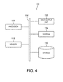
- the control device 100 is comprised of, for example, one or more computers, and as illustrated in a hardware configuration of Fig. 4 , it includes a processor 111, a memory 112, a storage 113, a console 114, an input/output (I/O) unit 115, and a bus 116 that connects these components.
- the processor 111 collaborates with at least either one of the memory 112 and the storage 113, to execute a program temporarily stored in the memory 112 or stored in the storage 113, and performs output and input of data through at least either one of the console 114 and the input/output unit 115, according to the executed result.
- the program may be provided to the system in advance, or may be provided from outside of the system by a storage medium or through a communication line.
- Fig. 5 illustrates the functions realized by the control device 100 as imagination components (hereinafter, referred to as "functional blocks"). These functional blocks are merely formed by conveniently dividing the function of the control device 100 into two or more blocks, and do not mean that the hardware which constitutes the control device 100 is actually divided into such blocks. Moreover, each functional block is not necessarily realized by execution of the program, but may be realized by a circuit element dedicated to a predetermined operation (for example, a logic IC).
- the control device 100 may also be provided as hardware that is integrally formed with the matrix converter device 10.
- the control device 100 includes, as the functional blocks, a power generation instruction acquiring module 121, a power generation controlling module 122, a power generating state acquiring module 123, a phase adjustment switching module 124, and a setting acquiring module 125.
- the power generation instruction acquiring module 121 acquires, for example, a power generation start instruction, a power generation stop instruction, and a target value of power generation.
- power generation refers to output power from the matrix converter device 10 to the electric power system 8.
- the power generation controlling module 122 controls the matrix converters 30 to perform the power conversion between the power generator 7 and the electric power system 8.
- the power generating state acquiring module 123 acquires information indicative of the power generation from the power generation controlling module 122.
- the information acquired by the power generating state acquiring module 123 may be any kind of information as long as it is information indicative of an increase or a decrease of the power generation, and the information may be, for example, a wind velocity near the blades 6, a rotating speed of the blades 6 (or the power generator 7), or output power of the power generator 7.
- the phase adjustment switching module 124 controls the switches 74, 75 and 76 to change the paths R1, R2 and R3 into the cut-off state in response to an increase of the power generation, and to change the paths R1, R2 and R3 into the conducting state in response to a decrease of the power generation. For example, the phase adjustment switching module 124 changes the paths R1, R2 and R3 into the cut-off state when the value acquired by the power generating state acquiring module 123 exceeds a threshold, and it changes the paths R1, R2 and R3 into the conducting state when the value acquired by the power generating state acquiring module 123 does not exceed the threshold.
- the setting acquiring module 125 acquires settings for the phase adjustment switching module 124. For example, the setting acquiring module 125 acquires settings of whether the paths R1, R2 and R3 are always maintained in the conducting state, or whether the change between the conducting state and the cut-off state is to be performed according to the power generation.
- the control device 100 performs the controlling method as described below. As illustrated in Fig. 6 , the control device 100 controls the switches 74, 75 and 76 in response to the acquisition of the power generation start instruction by the power generation instruction acquiring module 121 so that the paths R1, R2 and R3 are changed into the conducting state (Step S1). That is, the control device 100 performs a control to close the switches 74, 75 and 76 by the phase adjustment switching module 124.
- control device 100 starts controlling the matrix converters 30 so that the power conversion is performed between the power generator 7 and the electric power system 8 (Step S2).
- the control device 100 controls the matrix converters 30 by the power generation controlling module 122.
- the power generation controlling module 122 controls the matrix converters 30 so that an actual power generation approaches the target value acquired by the power generation instruction acquiring module 121.
- the control device 100 checks the settings acquired by the setting acquiring module 125 (Step S3). If the settings to perform the switching between the conducting state and the cut-off state according to the power generation are confirmed, the control device 100 checks whether the power generation exceeds a predetermined threshold B (Step S4).
- control device 100 checks whether the paths R1, R2 and R3 are in the conducting state (Step S5).
- Step S6 the control device 100 controls the switches 74, 75 and 76 so that the paths R1, R2 and R3 are changed into the cut-off state. That is, the control device 100 performs a control to open the switches 74, 75 and 76 by the phase adjustment switching module 124.
- Step S5 if it is confirmed that the paths R1, R2 and R3 are not in the conducting state, the control device 100 does not perform Step S6.
- Step S7 If settings to always maintain the paths R1, R2 and R3 in the conducting state are confirmed at Step S3, or if it is confirmed that the measurement related to the power generation does not exceed the threshold B at Step S4, the control device 100 checks whether the paths R1, R2 and R3 are in the conducting state (Step S7).
- Step S8 the control device 100 controls the switches 74, 75 and 76 to change the paths R1, R2 and R3 into the conducting state. That is, the control device 100 performs a control to close the switches 74, 75 and 76 by the phase adjustment switching module 124.
- Step S7 if it is confirmed that the paths R1, R2 and R3 are in the conducting state, the control device 100 does not perform Step S8.
- Steps S6 and S8 the switches 74, 75 and 76 are controlled to change the paths R1, R2 and R3 into the cut-off state according to the increase in the power generation, and to change the path for phase adjustment into the conducting state according to the decrease in the power generation.
- the control device 100 checks whether the power generation stop instruction is acquired by the power generation instruction acquiring module 121 (Step S9). If it is confirmed that the power generation stop instruction is not acquired, the control device 100 returns the control procedure to Step S3. If the acquisition of the power generation stop instruction is confirmed, the control device 100 suspends the control of the matrix converters 30 by the power generation controlling module 122 (Step S10).
- the filter 50 is provided on the electric power system 8 side of each matrix converter 30.
- the phase of current advances compared with the phase of voltage between the matrix converters 30 and the electric power system 8. Therefore, the power factor tends to be lowered.
- the power factor is possible to be raised by controlling the matrix converters 30, the power factor may not fully be raised in situations with low power generation.
- the inductors 71, 72 and 73 for phase adjustment are bridged between the power transmission path 20 and the neutral point P3, the advancing of the phase of current can be reduced. Thus, even if the power generation is low, the power factor can fully be raised. Therefore, the power factor can be adjusted more appropriately, while using the matrix converters 30.
- the power generating device 2 includes a plurality of matrix converters 30 which are mutually connected in series.
- the power transmission path 20 includes the main transformer 21, the first power lines 24 which connect the matrix converters 30 with the main transformer 21, and the second power line 25 which connects the electric power system 8 with the main transformer 21.
- the inductors 71, 72 and 73 are provided for each matrix converter 30, and they are bridged between the first power lines 24 and the neutral point P3. Since the voltages in the first power lines 24 are lower than the voltage in the second power line 25, installation of the inductors for phase adjustment is easier than installing the inductors 71, 72 and 73 between the second power line 25 and the neutral point P3.
- the power generation element of the power generating device 2 is a wind power generator.
- the wind power generating devices are often installed, for example, at locations where maintenance is typically difficult, such as on the sea.
- the matrix converters 30 are used for the power conversion of the power generating device 2, the frequency of maintenance of the power generating device tends to be lowered than the case where converters and inverters are used. Therefore, the adoption of the matrix converters 30 becomes more useful by applying the power generation element to the wind power generator.
- the control device 100 includes the power generation controlling module 122 for controlling the matrix converters 30 to perform the power conversion between the power generator 7 and the electric power system 8, and the phase adjustment switching module 124 for controlling the switches 74, 75 and 76 to change the paths R1, R2 and R3 into the cut-off state in response to the increase in the power generation, and to change the paths R1, R2 and R3 into the conducting state in response to the decrease in the power generation.
- the power generation controlling module 122 for controlling the matrix converters 30 to perform the power conversion between the power generator 7 and the electric power system 8
- the phase adjustment switching module 124 for controlling the switches 74, 75 and 76 to change the paths R1, R2 and R3 into the cut-off state in response to the increase in the power generation, and to change the paths R1, R2 and R3 into the conducting state in response to the decrease in the power generation.
- the controlling method by the control device 100 includes controlling the matrix converters 30 to perform the power conversion between the power generator 7 and the electric power system 8, and controlling the switches 74, 75 and 76 to change the paths R1, R2 and R3 into the cut-off state in response to the increase in the power generation, and to change the paths R1, R2 and R3 into the conducting state in response to the decrease in the power generation.
- Power consumption in the inductors 71, 72 and 73 can be reduced by changing the paths R1, R2 and R3 into the conducting state only when the power generation is low and the power factor is thus difficult to be raised.
- the inductors 71, 72 and 73 may be bridged between the second power lines 25 and the neutral point P3, as illustrated in a power generating device 2B according to a modification of Fig. 7 .
- the number of inductors 71, 72 and 73 can be reduced, compared with installing the inductors 71, 72 and 73 between the first power lines 24 and the neutral point P3.
- the main transformer 21 may further include third coils 26 which are wound so as to surround magnetic fluxes passing through the first coils 22 and the second coils 23, and the inductors 71, 72 and 73 may be bridged between the third coils 26 and the neutral point P3.
- voltage applied to the inductors 71, 72 and 73 can be lowered, compared with installing the inductors 71, 72 and 73 between the second power lines 25 and the neutral point P3.
- the number of inductors 71, 72 and 73 can be reduced, compared with installing the inductors 71, 72 and 73 between the first power lines 24 and the neutral point P3. Therefore, both the easiness of installing the inductors 71, 72 and 73, and the reduction in the number of inductors 71, 72 and 73 can be achieved.
- the power generating device 2 may further include sub-transformers 27 which intervene between the inductors 71, 72 and 73 and the power transmission path 20.
- a power generating device 2D according to a modification of Fig. 9 illustrates a configuration in which the inductors 71, 72 and 73 are connected with the second power lines 25 via the sub-transformers 27. By the sub-transformers 27 being intervened, voltage applied to the inductors 71, 72 and 73 can be lowered.
- Transformers for accessories may also be used as the sub-transformers 27.
- the voltage applied to the inductors 71, 72 and 73 can be lowered, without providing the sub-transformers 27 dedicated to the inductors 71, 72 and 73.
- the inductors 71, 72 and 73 for phase adjustment which are bridged between the first power lines 24 and the neutral point P3, the inductors 71, 72 and 73 which are bridged between the second power lines 25 and the neutral point P3, and the inductors 71, 72 and 73 which are bridged between the third coils 26 and the neutral point P3 may be adopted in combination.
- the switches 74, 75 and 76 are not essential.
- the power generation element of the power generating device 2 may be, for example, a solar cell, without limiting to the wind power generator.
Landscapes
- Engineering & Computer Science (AREA)
- Power Engineering (AREA)
- Combustion & Propulsion (AREA)
- Sustainable Development (AREA)
- Sustainable Energy (AREA)
- Chemical & Material Sciences (AREA)
- Life Sciences & Earth Sciences (AREA)
- Mechanical Engineering (AREA)
- General Engineering & Computer Science (AREA)
- Ac-Ac Conversion (AREA)
- Control Of Eletrric Generators (AREA)
- Supply And Distribution Of Alternating Current (AREA)
- Control Of Electrical Variables (AREA)
Abstract
Description
- The present disclosure relates to a power generating device, a control device, a controlling method, and a power generation system.
- Power generating devices provided with a power generation element and a power converter are widely used. The power converter converts power between the power generation element and an electric power system.
WO2012/111115A1 discloses a power generating device which uses a matrix converter as the power converter. - The power generating device is demanded for a function to appropriately adjust a power factor according to the electric power system. It is also desirable for the power generating device using the matrix converter that the power factor is more appropriately adjusted.
- The present disclosure provides a power generating device which uses a matrix converter device and is more appropriately adjustable of a power factor.
- According to one aspect of the present disclosure, a power generating device is provided, which includes a matrix converter device, a power transmission path for transmitting electric power between the matrix converter device and an electric power system, and at least one inductor for phase adjustment, bridged between the power transmission path and a neutral point.
- According to another aspect of the present disclosure, a control device for controlling the power generating device is provided. The control device includes a power generation controlling module for controlling the matrix converter device to perform power conversion between a power generation element and the electric power system, and a phase adjustment switching module for controlling the switch to change the path for phase adjustment into the cut-off state in response to an increase in power generation, and to change the path for phase adjustment into the conducting state in response to a decrease in the power generation.
- According to another aspect of the present disclosure, a method of controlling the power generating device is provided. The method includes controlling the matrix converter device to perform power conversion between a power generation element and the electric power system, and controlling the switch to change the path for phase adjustment into the cut-off state in response to an increase in power generation, and to change the path for phase adjustment into the conducting state in response to a decrease in the power generation.
- According to another aspect of the present disclosure, a power generation system is provided, which includes a matrix converter device, an inductor for phase adjustment, bridged between a power transmission path connecting the matrix converter device with an electric power system, and a neutral point. The system also includes a switch provided in series to the inductor for phase adjustment, between the power transmission path and the neutral point, and for switching a path for phase adjustment including the inductor for phase adjustment between a conducting state and a cut-off state. The system also includes a power generation controlling module for controlling the matrix converter device to perform power conversion between a power generation element and the electric power system, and a phase adjustment switching module for controlling the switch to change the path for phase adjustment into the cut-off state in response to an increase in power generation, and to change the path for phase adjustment into the conducting state in response to a decrease in the power generation.
- According to this disclosure, the power generating device which uses the matrix converter device and is more appropriately adjustable of the power factor can be provided.
- The present disclosure is illustrated by way of example and not by way of limitation in the figures of the accompanying drawings, in which the like reference numerals indicate like elements and in which:
-
Fig. 1 is a schematic diagram illustrating an outline configuration of a wind power generating device; -
Fig. 2 is a schematic diagram illustrating an outline configuration of a matrix converter device ofFig. 1 ; -
Fig. 3 is a schematic diagram illustrating an outline configuration of a matrix converter ofFig. 2 ; -
Fig. 4 is a block diagram illustrating a hardware configuration of a control device ofFig. 1 ; -
Fig. 5 is a block diagram illustrating a functional configuration of the control device ofFig. 1 ; -
Fig. 6 is a flowchart illustrating a procedure of a controlling method; -
Fig. 7 is a schematic diagram illustrating a modification of the power generating device; -
Fig. 8 is a schematic diagram illustrating another modification of the power generating device; and -
Fig. 9 is a schematic diagram illustrating still another modification of the power generating device. - Hereinafter, one embodiment is described in detail with reference to the accompanying drawings. In this description, same reference numerals are given to same elements or elements having same functions, and redundant explanation is omitted.
- As illustrated in
Fig. 1 , apower generation system 1 includes apower generating device 2 and acontrol device 100. Thepower generating device 2 is a wind power generating device, and includes atower body 3, anacelle 5, a set ofblades 6, a power generator 7, and amatrix converter device 10. Note that thepower generating device 2 may not be limited to the wind power generating device, but may be, for example, a solar power generating device. Note that the matrix converter device is one example of a power converter. - The
tower body 3 supports thenacelle 5, and accommodates thematrix converter device 10, apower transmission path 20, and thecontrol device 100. Thenacelle 5 accommodates the power generator 7. Theblades 6 are rotatably provided outside thenacelle 5, and rotate by wind force. The power generator 7 (power generation element) is, for example, a synchronous generator or an induction generator. The power generator 7 is driven by the rotation of theblades 6 to produce three-phase alternating current (AC) power of R-phase, S-phase and T-phase. That is, the power generator 7 is a wind-force power generator that is driven by wind force. - The
matrix converter device 10 converts output power of the power generator 7 according to anelectric power system 8. As illustrated inFig. 2 , thematrix converter device 10 has an R-phase unit 11, an S-phase unit 12 and a T-phase unit 13. The R-phase unit 11 is provided between the R-phase of the power generator 7 and a neutral point P1. The S-phase unit 12 is provided between the S-phase of the power generator 7 and the neutral point P1. The T-phase unit 13 is provided between the T-phase of the power generator 7 and the neutral point P1. - The R-
phase unit 11, the S-phase unit 12 and the T-phase unit 13 have threematrix converters 30, respectively (nine converters in total). The threematrix converters 30 of the R-phase unit 11 are bridged between the R-phase of the power generator 7 and the neutral point P1 in a state where thematrix converters 30 are mutually connected in series. That is, one end of the threematrix converters 30 connected in series is connected with the R-phase of the power generator 7, and the other end is connected with the neutral point P1. The threematrix converters 30 of the S-phase unit 12 are bridged between the S-phase of the power generator 7 and the neutral point P1 in a state where theconverters 30 are mutually connected in series. The threematrix converters 30 of the T-phase unit 13 are bridged between the T-phase of the power generator 7 and the neutral point P1 in a state where theconverters 30 are mutually connected in series. - The
power transmission path 20 includes amain transformer 21,first power lines 24, and asecond power line 25, and transmits electric power between thematrix converters 30 and theelectric power system 8. Themain transformer 21 is a three-phase transformer. Thefirst power lines 24 connectterminals matrix converters 30 with themain transformer 21. Thesecond power line 25 connects theelectric power system 8 with themain transformer 21. Themain transformer 21 includesfirst coils 22 connected with thefirst power lines 24, and asecond coil 23 connected with thesecond power line 25. Themain transformer 21 is configured so that theelectric power system 8 side is a high-voltage side. - As illustrated in
Fig. 3 , eachmatrix converter 30 includes a convertermain body 40, afilter 50, asnubber circuit 60, and the terminals 31-35. The convertermain body 40 has bidirectional switches 41-46. - The
bidirectional switches terminal 31 and theterminal 32 in a state where theswitches bidirectional switches terminal 33 via thefilter 50. - The
bidirectional switches switches bidirectional switches filter 50. - The
bidirectional switches switches bidirectional switches filter 50. - Each of the bidirectional switches 41-46 is comprised of, for example, two switching elements which are mutually connected in parallel and in opposite directions. The switching element may include, for example, a semiconductor switch, such as an IGBT (Insulated Gate Bipolar Transistor). Power conversion is performed between the
terminals terminals - The
filter 50 includescapacitors inductors capacitor 51 intervenes between the connection between thebidirectional switches capacitor 52 intervenes between the connection between thebidirectional switches capacitor 53 intervenes between the connection between thebidirectional switches inductor 54 intervenes between the connection of thebidirectional switches inductor 55 intervenes between the connection of thebidirectional switches inductor 56 intervenes between the connection of thebidirectional switches - The
snubber circuit 60 includesrectification circuits capacitor 63, and adischarge circuit 64. Therectification circuits main body 40 into direct current, and accumulate the direct current in thecapacitor 63. Thedischarge circuit 64 discharges the electric charge accumulated in thecapacitor 63, according to an electric discharge instruction. Thedischarge circuit 64 is comprised of, for example, a switching element such as an IGBT, and a resistor. - The terminal 31 of the
matrix converter 30 located closest to the power generator 7 is connected with the power generator 7, and theterminals 31 ofother matrix converters 30 are connected withadjacent matrix converters 30 on the power generator 7 side (refer toFig. 2 ). The terminal 32 of thematrix converter 30 located closest to the neutral point P1 is connected with the neutral point P1, and theterminals 32 ofother matrix converters 30 are connected withadjacent matrix converters 30 on the neutral point P1 side. Theterminals first coils 22 of themain transformer 21 through thefirst power lines 24. - An
inductor 71 for phase adjustment is bridged between thefirst power line 24 that connects the terminal 33 with thefirst coil 22, and a neutral point P3. Aninductor 72 for phase adjustment is bridged between thefirst power line 24 that connects the terminal 34 with thefirst coil 22, and the neutral point P3. Aninductor 73 for phase adjustment is bridged between thefirst power line 24 that connects the terminal 35 with thefirst coil 22, and the neutral point P3. That is, thepower generating device 2 includes theinductors power transmission path 20 and the neutral point P3. Theinductors matrix converter 30, and are bridged between thefirst power lines 24 and the neutral point P3. - The
power generating device 2 further includesswitches switch 74 is provided between thefirst power line 24 and the neutral point P3, in series to theinductor 71. Theswitch 74 closes and opens to switch a path R1 including the inductor 71 (path for phase adjustment) between a conducting state and a cut-off state, respectively. Theswitch 75 is provided between thefirst power line 24 and the neutral point P3, in series to theinductor 72. Theswitch 75 closes and opens to switch a path R2 including the inductor 72 (path for phase adjustment) between a conducting state and a cut-off state, respectively. Theswitch 76 is provided between thefirst power line 24 and the neutral point P3, in series to theinductor 73. Theswitch 76 closes and opens to switch a path R3 including the inductor 73 (path for phase adjustment) between a conducting state and a cut-off state, respectively. - The
control device 100 is comprised of, for example, one or more computers, and as illustrated in a hardware configuration ofFig. 4 , it includes aprocessor 111, amemory 112, astorage 113, aconsole 114, an input/output (I/O)unit 115, and abus 116 that connects these components. Theprocessor 111 collaborates with at least either one of thememory 112 and thestorage 113, to execute a program temporarily stored in thememory 112 or stored in thestorage 113, and performs output and input of data through at least either one of theconsole 114 and the input/output unit 115, according to the executed result. Thus, various functions of thecontrol device 100 are realized. Note that the program may be provided to the system in advance, or may be provided from outside of the system by a storage medium or through a communication line. -
Fig. 5 illustrates the functions realized by thecontrol device 100 as imagination components (hereinafter, referred to as "functional blocks"). These functional blocks are merely formed by conveniently dividing the function of thecontrol device 100 into two or more blocks, and do not mean that the hardware which constitutes thecontrol device 100 is actually divided into such blocks. Moreover, each functional block is not necessarily realized by execution of the program, but may be realized by a circuit element dedicated to a predetermined operation (for example, a logic IC). Thecontrol device 100 may also be provided as hardware that is integrally formed with thematrix converter device 10. - As illustrated in
Fig. 5 , thecontrol device 100 includes, as the functional blocks, a power generationinstruction acquiring module 121, a powergeneration controlling module 122, a power generatingstate acquiring module 123, a phaseadjustment switching module 124, and asetting acquiring module 125. - The power generation
instruction acquiring module 121 acquires, for example, a power generation start instruction, a power generation stop instruction, and a target value of power generation. Note that the term "power generation" refers to output power from thematrix converter device 10 to theelectric power system 8. The powergeneration controlling module 122 controls thematrix converters 30 to perform the power conversion between the power generator 7 and theelectric power system 8. - The power generating
state acquiring module 123 acquires information indicative of the power generation from the powergeneration controlling module 122. The information acquired by the power generatingstate acquiring module 123 may be any kind of information as long as it is information indicative of an increase or a decrease of the power generation, and the information may be, for example, a wind velocity near theblades 6, a rotating speed of the blades 6 (or the power generator 7), or output power of the power generator 7. - The phase
adjustment switching module 124 controls theswitches adjustment switching module 124 changes the paths R1, R2 and R3 into the cut-off state when the value acquired by the power generatingstate acquiring module 123 exceeds a threshold, and it changes the paths R1, R2 and R3 into the conducting state when the value acquired by the power generatingstate acquiring module 123 does not exceed the threshold. - The
setting acquiring module 125 acquires settings for the phaseadjustment switching module 124. For example, thesetting acquiring module 125 acquires settings of whether the paths R1, R2 and R3 are always maintained in the conducting state, or whether the change between the conducting state and the cut-off state is to be performed according to the power generation. - The
control device 100 performs the controlling method as described below. As illustrated inFig. 6 , thecontrol device 100 controls theswitches instruction acquiring module 121 so that the paths R1, R2 and R3 are changed into the conducting state (Step S1). That is, thecontrol device 100 performs a control to close theswitches adjustment switching module 124. - Next, the
control device 100 starts controlling thematrix converters 30 so that the power conversion is performed between the power generator 7 and the electric power system 8 (Step S2). Thecontrol device 100 controls thematrix converters 30 by the powergeneration controlling module 122. The powergeneration controlling module 122 controls thematrix converters 30 so that an actual power generation approaches the target value acquired by the power generationinstruction acquiring module 121. - Next, the
control device 100 checks the settings acquired by the setting acquiring module 125 (Step S3). If the settings to perform the switching between the conducting state and the cut-off state according to the power generation are confirmed, thecontrol device 100 checks whether the power generation exceeds a predetermined threshold B (Step S4). - If it is confirmed that the power generation exceeds the threshold B, the
control device 100 checks whether the paths R1, R2 and R3 are in the conducting state (Step S5). - If it is confirmed that the paths R1, R2 and R3 are in the conducting state, the
control device 100 controls theswitches control device 100 performs a control to open theswitches adjustment switching module 124. At Step S5, if it is confirmed that the paths R1, R2 and R3 are not in the conducting state, thecontrol device 100 does not perform Step S6. - If settings to always maintain the paths R1, R2 and R3 in the conducting state are confirmed at Step S3, or if it is confirmed that the measurement related to the power generation does not exceed the threshold B at Step S4, the
control device 100 checks whether the paths R1, R2 and R3 are in the conducting state (Step S7). - If it is confirmed that the paths R1, R2 and R3 are not in the conducting state, the
control device 100 controls theswitches control device 100 performs a control to close theswitches adjustment switching module 124. At Step S7, if it is confirmed that the paths R1, R2 and R3 are in the conducting state, thecontrol device 100 does not perform Step S8. - By Steps S6 and S8, the
switches - Next, the
control device 100 checks whether the power generation stop instruction is acquired by the power generation instruction acquiring module 121 (Step S9). If it is confirmed that the power generation stop instruction is not acquired, thecontrol device 100 returns the control procedure to Step S3. If the acquisition of the power generation stop instruction is confirmed, thecontrol device 100 suspends the control of thematrix converters 30 by the power generation controlling module 122 (Step S10). - As described above, the
filter 50 is provided on theelectric power system 8 side of eachmatrix converter 30. Thus, the phase of current advances compared with the phase of voltage between thematrix converters 30 and theelectric power system 8. Therefore, the power factor tends to be lowered. Although the power factor is possible to be raised by controlling thematrix converters 30, the power factor may not fully be raised in situations with low power generation. - According to the
power generating device 2, since theinductors power transmission path 20 and the neutral point P3, the advancing of the phase of current can be reduced. Thus, even if the power generation is low, the power factor can fully be raised. Therefore, the power factor can be adjusted more appropriately, while using thematrix converters 30. - The
power generating device 2 includes a plurality ofmatrix converters 30 which are mutually connected in series. Thepower transmission path 20 includes themain transformer 21, thefirst power lines 24 which connect thematrix converters 30 with themain transformer 21, and thesecond power line 25 which connects theelectric power system 8 with themain transformer 21. Theinductors matrix converter 30, and they are bridged between thefirst power lines 24 and the neutral point P3. Since the voltages in thefirst power lines 24 are lower than the voltage in thesecond power line 25, installation of the inductors for phase adjustment is easier than installing theinductors second power line 25 and the neutral point P3. - The power generation element of the
power generating device 2 is a wind power generator. The wind power generating devices are often installed, for example, at locations where maintenance is typically difficult, such as on the sea. On the other hand, if thematrix converters 30 are used for the power conversion of thepower generating device 2, the frequency of maintenance of the power generating device tends to be lowered than the case where converters and inverters are used. Therefore, the adoption of thematrix converters 30 becomes more useful by applying the power generation element to the wind power generator. - The
control device 100 includes the powergeneration controlling module 122 for controlling thematrix converters 30 to perform the power conversion between the power generator 7 and theelectric power system 8, and the phaseadjustment switching module 124 for controlling theswitches - The controlling method by the
control device 100 includes controlling thematrix converters 30 to perform the power conversion between the power generator 7 and theelectric power system 8, and controlling theswitches inductors - Note that the
inductors second power lines 25 and the neutral point P3, as illustrated in apower generating device 2B according to a modification ofFig. 7 . In this case, the number ofinductors inductors first power lines 24 and the neutral point P3. - As illustrated in a
power generating device 2C according to a modification ofFig. 8 , themain transformer 21 may further includethird coils 26 which are wound so as to surround magnetic fluxes passing through thefirst coils 22 and the second coils 23, and theinductors third coils 26 and the neutral point P3. In this case, voltage applied to theinductors inductors second power lines 25 and the neutral point P3. Further, the number ofinductors inductors first power lines 24 and the neutral point P3. Therefore, both the easiness of installing theinductors inductors - The
power generating device 2 may further includesub-transformers 27 which intervene between theinductors power transmission path 20. Apower generating device 2D according to a modification ofFig. 9 illustrates a configuration in which theinductors second power lines 25 via the sub-transformers 27. By the sub-transformers 27 being intervened, voltage applied to theinductors - Transformers for accessories (for example, a cooling pump or a cooling fan) may also be used as the sub-transformers 27. In this case, the voltage applied to the
inductors inductors - In the foregoing specification and specific embodiments of the present disclosure have been described. However, one of ordinary skill in the art appreciates that various modifications and changes can be made without departing from the scope of the present disclosure as set forth in the appended claims below. Accordingly, the specification and figures are to be regarded in an illustrative rather than a restrictive sense, and all such modifications are intended to be included within the scope of present disclosure. The benefits and advantages, solutions to problems, and any element(s) that may cause any benefit, advantage and/or solution to occur or become more pronounced are not to be construed as a critical, required and/or essential features or elements of any or all the claims. The present disclosure is defined solely by the appended claims including any amendments made during the pendency of this application and all equivalents of those claims as issued.
- For example, some or all of the
inductors first power lines 24 and the neutral point P3, theinductors second power lines 25 and the neutral point P3, and theinductors third coils 26 and the neutral point P3 may be adopted in combination. Theswitches power generating device 2 may be, for example, a solar cell, without limiting to the wind power generator.
Claims (10)
- A power generating device (2), comprising:a matrix converter device (10, 30);a power transmission path (20) for transmitting electric power between the matrix converter device (10, 30) and an electric power system (8); andat least one inductor (71, 72, 73) for phase adjustment, bridged between the power transmission path (20) and a neutral point (P3).
- The power generating device (2) of claim 1, wherein the matrix converter device (10, 30) includes a plurality of matrix converters (30), the matrix converters (30) being connected with each other in series,
wherein the power transmission path (20) includes a main transformer (21), first power lines (24) connecting the matrix converters (30) with the main transformer (21), and a second power line (25) connecting the electric power system (8) with the main transformer (21), and
wherein the inductor (71, 72, 73) for phase adjustment is provided for each matrix converter (30), and is bridged between each of the first power lines (24) and the neutral point (P3). - The power generating device (2) of claim 1, wherein the power transmission path (20) includes a main transformer (21), a first power line (24) connecting the matrix converter (30) with the main transformer (21), and a second power line (25) connecting the electric power system (8) with the main transformer (21), and
wherein the inductor (71, 72, 73) for phase adjustment is bridged between the second power line (25) and the neutral point (P3). - The power generating device (2) of claim 1, wherein the power transmission path (20) includes a main transformer (21), a first power line (24) connecting the matrix converter (30) with the main transformer (21), and a second power line (25) connecting the electric power system (8) with the main transformer (21),
wherein the main transformer (21) includes a first coil (22) connected with the first power line (24), a second coil (23) connected with the second power line (25), and a third coil (26) wound so as to surround a magnetic flux passing through the first coil (22) and the second coil (23), and
wherein the inductor (71, 72, 73) for phase adjustment is bridged between the third coil (26) and the neutral point (P3). - The power generating device (2) of claim 1, further comprising a sub-transformer (27) that intervenes between the inductor (71, 72, 73) for phase adjustment and the power transmission path (20).
- The power generating device (2) of any one of claims 1 to 5, wherein a power generation element (7) is a wind power generator.
- The power generating device (2) of any one of claims 1 to 6, further comprising a switch (74, 75, 76) provided in series to the inductor (71, 72, 73) for phase adjustment, between the power transmission path (20) and the neutral point (P3), and for switching a path (R1, R2, R3) for phase adjustment including the inductor (71, 72, 73) for phase adjustment between a conducting state and a cut-off state.
- A control device (100) for controlling the power generating device (2) of claim 7, comprising:a power generation controlling module (122) for controlling the matrix converter device (10, 30) to perform power conversion between a power generation element (7) and the electric power system (8); anda phase adjustment switching module (124) for controlling the switch (74, 75, 76) to change the path (R1, R2, R3) for phase adjustment into the cut-off state in response to an increase in power generation, and to change the path (R1, R2, R3) for phase adjustment into the conducting state in response to a decrease in the power generation.
- A method of controlling the power generating device (2) of claim 7, comprising:controlling the matrix converter device (10, 30) to perform power conversion between a power generation element (7) and the electric power system (8); andcontrolling the switch (74, 75, 76) to change the path (R1, R2, R3) for phase adjustment into the cut-off state in response to an increase in power generation, and to change the path (R1, R2, R3) for phase adjustment into the conducting state in response to a decrease in the power generation.
- A power generation system (1), comprising:a matrix converter device (10, 30);an inductor (71, 72, 73) for phase adjustment, bridged between a power transmission path (20) connecting the matrix converter device (10, 30) with an electric power system (8), and a neutral point (P3);a switch (74, 75, 76) provided in series to the inductor (71, 72, 73) for phase adjustment, between the power transmission path (20) and the neutral point (P3), and for switching a path (R1, R2, R3) for phase adjustment including the inductor (71, 72, 73) for phase adjustment between a conducting state and a cut-off state;a power generation controlling module (122) for controlling the matrix converter device (10, 30) to perform power conversion between a power generation element (7) and the electric power system (8); anda phase adjustment switching module (124) for controlling the switch (74, 75, 76) to change the path (R1, R2, R3) for phase adjustment into the cut-off state in response to an increase in power generation, and to change the path (R1, R2, R3) for phase adjustment into the conducting state in response to a decrease in the power generation.
Applications Claiming Priority (1)
| Application Number | Priority Date | Filing Date | Title |
|---|---|---|---|
| JP2014065642A JP6237400B2 (en) | 2014-03-27 | 2014-03-27 | Power generation device, control device, control method, power generation system, power conversion device and system |
Publications (1)
| Publication Number | Publication Date |
|---|---|
| EP2924865A1 true EP2924865A1 (en) | 2015-09-30 |
Family
ID=53039174
Family Applications (1)
| Application Number | Title | Priority Date | Filing Date |
|---|---|---|---|
| EP15158155.0A Withdrawn EP2924865A1 (en) | 2014-03-27 | 2015-03-09 | Power generating device, control device, controlling method and power generation system |
Country Status (4)
| Country | Link |
|---|---|
| US (1) | US9537415B2 (en) |
| EP (1) | EP2924865A1 (en) |
| JP (1) | JP6237400B2 (en) |
| CN (1) | CN104953612A (en) |
Families Citing this family (1)
| Publication number | Priority date | Publication date | Assignee | Title |
|---|---|---|---|---|
| WO2015102049A1 (en) * | 2014-01-06 | 2015-07-09 | 東芝三菱電機産業システム株式会社 | Electric power conversion system |
Citations (3)
| Publication number | Priority date | Publication date | Assignee | Title |
|---|---|---|---|---|
| WO2004042890A1 (en) * | 2002-11-05 | 2004-05-21 | Railpower Technologies Corp. | Direct turbogenerator |
| JP2010093868A (en) * | 2008-10-03 | 2010-04-22 | Yanmar Co Ltd | Bidirectional power converter |
| WO2012111115A1 (en) | 2011-02-16 | 2012-08-23 | 株式会社安川電機 | Power converter device for wind-power electricity-generation, wind-power electricity-generation device, wind farm, and wind turbine manufacturing method |
Family Cites Families (22)
| Publication number | Priority date | Publication date | Assignee | Title |
|---|---|---|---|---|
| JPS57199022A (en) * | 1981-05-30 | 1982-12-06 | Toshiba Corp | Static reactive power compensating device |
| JPH06253447A (en) * | 1993-03-01 | 1994-09-09 | Nissin Electric Co Ltd | Protective relay for shunt reactor of phase modifying equipment |
| US6900998B2 (en) * | 2002-05-31 | 2005-05-31 | Midwest Research Institute | Variable-speed wind power system with improved energy capture via multilevel conversion |
| US8514601B2 (en) * | 2009-08-17 | 2013-08-20 | Ideal Power Converters, Inc. | Power conversion with added pseudo-phase |
| EP2025051B1 (en) * | 2006-06-06 | 2014-12-31 | Ideal Power Inc. | Universal power converter |
| US7848121B2 (en) * | 2007-05-14 | 2010-12-07 | Honeywell International Inc. | Advanced matrix converter and method for operation |
| US8120932B2 (en) * | 2008-07-01 | 2012-02-21 | American Superconductor Corporation | Low voltage ride through |
| JP4654423B2 (en) * | 2008-07-22 | 2011-03-23 | 独立行政法人産業技術総合研究所 | Power converter |
| PT2340595E (en) * | 2008-10-20 | 2012-09-06 | Siemens Ag | Apparatus and method for reactive power compensation of a test transformer |
| CN101958657A (en) * | 2009-07-17 | 2011-01-26 | 华为技术有限公司 | Power supply switching circuit, equipment and alternate control method of power factor correction circuit |
| JP5360125B2 (en) * | 2011-04-26 | 2013-12-04 | 株式会社安川電機 | Series multiple power converter |
| JP2013110884A (en) * | 2011-11-22 | 2013-06-06 | Yamaguchi Univ | Reactive power compensation device and control method for the same |
| WO2013080744A1 (en) * | 2011-11-30 | 2013-06-06 | 株式会社安川電機 | Matrix converter |
| EP2728729A2 (en) * | 2012-10-30 | 2014-05-07 | Kabushiki Kaisha Yaskawa Denki | Matrix converter |
| KR20140074849A (en) * | 2012-12-10 | 2014-06-18 | 가부시키가이샤 야스카와덴키 | Matrix converter and method for controlling matrix converter |
| JP5569583B2 (en) * | 2012-12-21 | 2014-08-13 | 株式会社安川電機 | Matrix converter |
| JP2015010579A (en) * | 2013-07-01 | 2015-01-19 | 株式会社安川電機 | Wind power generation system |
| US9318992B2 (en) * | 2013-08-22 | 2016-04-19 | Yaskawa America, Inc. | Drive circuit for a pre-phase AC motor |
| JP5888318B2 (en) * | 2013-12-26 | 2016-03-22 | 株式会社安川電機 | Matrix converter, wind power generation system, and matrix converter control method |
| JP2015186431A (en) * | 2014-03-26 | 2015-10-22 | 株式会社安川電機 | Power converter, controller for power converter, and control method for power converter |
| JP2015201996A (en) * | 2014-04-09 | 2015-11-12 | 株式会社安川電機 | Power conversion device, control device for power conversion device, and control method for power conversion device |
| JP2016019297A (en) * | 2014-07-04 | 2016-02-01 | 株式会社安川電機 | Serial multiple matrix converter, power generation system, and power factor control method |
-
2014
- 2014-03-27 JP JP2014065642A patent/JP6237400B2/en active Active
-
2015
- 2015-01-29 CN CN201510047938.3A patent/CN104953612A/en active Pending
- 2015-03-09 EP EP15158155.0A patent/EP2924865A1/en not_active Withdrawn
- 2015-03-12 US US14/645,426 patent/US9537415B2/en active Active
Patent Citations (4)
| Publication number | Priority date | Publication date | Assignee | Title |
|---|---|---|---|---|
| WO2004042890A1 (en) * | 2002-11-05 | 2004-05-21 | Railpower Technologies Corp. | Direct turbogenerator |
| JP2010093868A (en) * | 2008-10-03 | 2010-04-22 | Yanmar Co Ltd | Bidirectional power converter |
| WO2012111115A1 (en) | 2011-02-16 | 2012-08-23 | 株式会社安川電機 | Power converter device for wind-power electricity-generation, wind-power electricity-generation device, wind farm, and wind turbine manufacturing method |
| EP2677168A1 (en) * | 2011-02-16 | 2013-12-25 | Kabushiki Kaisha Yaskawa Denki | Matrix converter device for wind-power electricity-generation, wind-power electricity-generation device, wind farm, and wind turbine manufacturing method |
Also Published As
| Publication number | Publication date |
|---|---|
| US20150280599A1 (en) | 2015-10-01 |
| CN104953612A (en) | 2015-09-30 |
| JP2015191247A (en) | 2015-11-02 |
| US9537415B2 (en) | 2017-01-03 |
| JP6237400B2 (en) | 2017-11-29 |
Similar Documents
| Publication | Publication Date | Title |
|---|---|---|
| US9407133B1 (en) | Active power conditioner | |
| US20100102762A1 (en) | Power converter | |
| WO2015030883A2 (en) | Methods and systems for an integrated electrical generator with hybrid rectifier | |
| JP2017118806A (en) | Power converter and control method | |
| EP3568907B1 (en) | Switching strategy for increased efficiency of power converters | |
| EP3556004A2 (en) | Space vector modulation in aerospace applications | |
| US20140103886A1 (en) | Method for producing reactive current with a converter and converter arrangement and energy supply plant | |
| EP3566293B1 (en) | Grounding scheme for power converters with silicon carbide mosfets and method | |
| US10669989B2 (en) | Apparatus for driving and controlling converters and switching element modules in a wind power generation system | |
| US9537415B2 (en) | Power generating device, control device, controlling method and power generation system | |
| CN106788109B (en) | Motor servo controller and control method thereof | |
| CN205811846U (en) | The device of suppression three-phase voltage source type PWM rectifier power-on impact current | |
| RU2411629C1 (en) | Multi-level transistor converter of frequency for control of ac electric motor | |
| JP6746046B1 (en) | Power converter | |
| JP2008048568A (en) | Motor-driven controller | |
| US10122253B2 (en) | Power conversion apparatus and initial charging method of the same | |
| RU151864U1 (en) | POWER SUPPLY SYSTEM FOR OWN NEEDS OF A POWER PLANT | |
| JP2022046763A (en) | A system that converts DC power including filtering means into three-phase AC power | |
| US10063172B2 (en) | Controlled braking of a generator | |
| CN105471341A (en) | Asynchronous starting structure, asynchronous starting method and asynchronous starting device of brushless doubly-fed machine | |
| CN104734187B (en) | Energy storage type intelligent transformer for wind power generation system | |
| CN113315114B (en) | Multiphase fan direct current grid-connected system and low-voltage ride through control method thereof | |
| KR101475025B1 (en) | A control system operating a rotary machine | |
| CN112292804A (en) | Method for controlling a power converter having an inverter block with silicon carbide MOSFETs | |
| JP2005176585A (en) | Device for controlling capacitor using thyristor |
Legal Events
| Date | Code | Title | Description |
|---|---|---|---|
| PUAI | Public reference made under article 153(3) epc to a published international application that has entered the european phase |
Free format text: ORIGINAL CODE: 0009012 |
|
| AK | Designated contracting states |
Kind code of ref document: A1 Designated state(s): AL AT BE BG CH CY CZ DE DK EE ES FI FR GB GR HR HU IE IS IT LI LT LU LV MC MK MT NL NO PL PT RO RS SE SI SK SM TR |
|
| AX | Request for extension of the european patent |
Extension state: BA ME |
|
| 17P | Request for examination filed |
Effective date: 20151026 |
|
| RBV | Designated contracting states (corrected) |
Designated state(s): AL AT BE BG CH CY CZ DE DK EE ES FI FR GB GR HR HU IE IS IT LI LT LU LV MC MK MT NL NO PL PT RO RS SE SI SK SM TR |
|
| STAA | Information on the status of an ep patent application or granted ep patent |
Free format text: STATUS: THE APPLICATION HAS BEEN WITHDRAWN |
|
| 18W | Application withdrawn |
Effective date: 20160725 |