EP2924534A2 - Cooking appliance and light-emitting knob assembly thereof - Google Patents
Cooking appliance and light-emitting knob assembly thereof Download PDFInfo
- Publication number
- EP2924534A2 EP2924534A2 EP15157190.8A EP15157190A EP2924534A2 EP 2924534 A2 EP2924534 A2 EP 2924534A2 EP 15157190 A EP15157190 A EP 15157190A EP 2924534 A2 EP2924534 A2 EP 2924534A2
- Authority
- EP
- European Patent Office
- Prior art keywords
- light
- knob
- translucent
- emitting
- guide member
- Prior art date
- Legal status (The legal status is an assumption and is not a legal conclusion. Google has not performed a legal analysis and makes no representation as to the accuracy of the status listed.)
- Withdrawn
Links
- 238000010411 cooking Methods 0.000 title claims abstract description 35
- 239000004417 polycarbonate Substances 0.000 claims description 8
- 239000000463 material Substances 0.000 claims description 6
- 229920000515 polycarbonate Polymers 0.000 claims description 6
- NIXOWILDQLNWCW-UHFFFAOYSA-N acrylic acid group Chemical group C(C=C)(=O)O NIXOWILDQLNWCW-UHFFFAOYSA-N 0.000 claims description 3
- 239000003795 chemical substances by application Substances 0.000 claims description 3
- 230000006872 improvement Effects 0.000 abstract description 3
- 230000005540 biological transmission Effects 0.000 description 5
- 230000005489 elastic deformation Effects 0.000 description 5
- 238000010586 diagram Methods 0.000 description 4
- 238000007789 sealing Methods 0.000 description 4
- 230000009471 action Effects 0.000 description 3
- 230000000694 effects Effects 0.000 description 3
- 230000004048 modification Effects 0.000 description 3
- 238000012986 modification Methods 0.000 description 3
- 238000010438 heat treatment Methods 0.000 description 2
- 230000006698 induction Effects 0.000 description 2
- 238000007792 addition Methods 0.000 description 1
- 230000000712 assembly Effects 0.000 description 1
- 238000000429 assembly Methods 0.000 description 1
- 230000009286 beneficial effect Effects 0.000 description 1
- 230000008859 change Effects 0.000 description 1
- 239000004020 conductor Substances 0.000 description 1
- 230000037430 deletion Effects 0.000 description 1
- 238000012217 deletion Methods 0.000 description 1
- 238000001125 extrusion Methods 0.000 description 1
- 239000012530 fluid Substances 0.000 description 1
- 239000000446 fuel Substances 0.000 description 1
- 230000004927 fusion Effects 0.000 description 1
- 238000000034 method Methods 0.000 description 1
- 230000008569 process Effects 0.000 description 1
- 238000009877 rendering Methods 0.000 description 1
- 238000003466 welding Methods 0.000 description 1
Images



Classifications
-
- G—PHYSICS
- G05—CONTROLLING; REGULATING
- G05G—CONTROL DEVICES OR SYSTEMS INSOFAR AS CHARACTERISED BY MECHANICAL FEATURES ONLY
- G05G1/00—Controlling members, e.g. knobs or handles; Assemblies or arrangements thereof; Indicating position of controlling members
- G05G1/08—Controlling members for hand actuation by rotary movement, e.g. hand wheels
- G05G1/10—Details, e.g. of discs, knobs, wheels or handles
- G05G1/105—Details, e.g. of discs, knobs, wheels or handles comprising arrangements for illumination
-
- F—MECHANICAL ENGINEERING; LIGHTING; HEATING; WEAPONS; BLASTING
- F24—HEATING; RANGES; VENTILATING
- F24C—DOMESTIC STOVES OR RANGES ; DETAILS OF DOMESTIC STOVES OR RANGES, OF GENERAL APPLICATION
- F24C3/00—Stoves or ranges for gaseous fuels
- F24C3/12—Arrangement or mounting of control or safety devices
- F24C3/124—Control panels
-
- Y—GENERAL TAGGING OF NEW TECHNOLOGICAL DEVELOPMENTS; GENERAL TAGGING OF CROSS-SECTIONAL TECHNOLOGIES SPANNING OVER SEVERAL SECTIONS OF THE IPC; TECHNICAL SUBJECTS COVERED BY FORMER USPC CROSS-REFERENCE ART COLLECTIONS [XRACs] AND DIGESTS
- Y02—TECHNOLOGIES OR APPLICATIONS FOR MITIGATION OR ADAPTATION AGAINST CLIMATE CHANGE
- Y02B—CLIMATE CHANGE MITIGATION TECHNOLOGIES RELATED TO BUILDINGS, e.g. HOUSING, HOUSE APPLIANCES OR RELATED END-USER APPLICATIONS
- Y02B40/00—Technologies aiming at improving the efficiency of home appliances, e.g. induction cooking or efficient technologies for refrigerators, freezers or dish washers
Definitions
- the present technical solution relates to the field of cooking appliances and the field of light-emitting knob assemblies for cooking appliances.
- a knob that has a light-emitting function and is used for an existing cooking appliance generally has a complicated assembly structure, thereby causing a low assembly efficiency.
- the knob that has the light-emitting function and is used for the existing cooking appliance also has a less diversified light guide structure and lacks an improvement in structure.
- a primary objective of the present technical solution is to propose a new improvement for a cooking appliance and a light-emitting knob assembly thereof.
- a light-emitting knob assembly for a cooking appliance proposed by the present technical solution includes: a knob and a light guide member, where the light guide member is fixed on the knob in an engaging manner after the knob is assembled.
- the "engaging manner" should be understood as any connection solution of implementing the connection and fixation by using elasticity of a connecting piece, which can be obviously conceived of and applied to the present technical solution by a person of ordinary skill in the art on the basis of this specification, the prior art and common general knowledge.
- the assembly efficiency can be improved.
- the light guide member includes a translucent ring, and a side wall of the translucent ring is used as a translucent surface; and the translucent ring is located at the bottom of the knob, and the side wall of the translucent ring is smoothly connected to a side wall of the knob.
- the present technical solution proposes an entirely new structure of a light-emitting knob assembly for a cooking appliance, which not only helps to improve the assembly efficiency but also helps to improve an esthetic feeling of the appearance of the light-emitting knob assembly.
- the knob includes a rotating shaft receiving portion;
- the light guide member includes a translucent ring, and the translucent ring is provided with a hollow portion for the rotating shaft receiving portion to pass through; one end of the hollow portion is provided with a light receiving surface, and the other end is provided with a chamfer; and the chamfer is used for at least partially reflecting light entering from the light receiving surface.
- the chamfer is used for changing a transmission direction of light entering from the light receiving surface, which helps to implement diversified modeling of the light guide member.
- a side wall of the translucent ring is used as a translucent surface; the translucent ring is located at the bottom of the knob, and the side wall of the translucent ring is smoothly connected to a side wall of the knob; the hollow portion extends in a direction away from the chamfer to form a hollow cylinder portion, and the light receiving surface is disposed at a tip of the cylinder portion; and the chamfer is used for at least partially reflecting light entering from the light receiving surface towards the side wall of the translucent ring.
- the chamfer is used for changing a transmission direction of light entering from the light receiving surface, making it possible that the light receiving surface is disposed on the side wall of the translucent ring in a structure according to the present technical solution.
- the light guide member includes a translucent surface; and the translucent surface is a frosted surface.
- the translucent surface can achieve an optimal light transmission effect.
- the light guide member includes a light shading surface; and the light shading surface is a smooth surface.
- the light shading surface is used for preventing light from getting out of the light guide member from the light shading surface or reducing the possibility. By using a smooth surface, the light shading surface can achieve an optimal light shading effect.
- the light guide member is integrally formed by using any one of the following materials:
- the light guide member includes a protruding portion; the volume of the protruding portion gradually dwindles in a direction away from a light source; and the bottom of the knob is provided with an opening for the protruding portion to pass through. Because the volume of the protruding portion gradually dwindles in the direction away from the light source, the protruding portion can achieve an optimal light guide effect. It should be noted herein that "the volume gradually dwindles" is broadly understood, that is, it may literally mean that the volume gradually dwindles, and it may also mean that the overall volume shows a trend of gradually dwindling.
- a top wall of the knob is provided with a through hole; and a tail end of the protruding portion is placed into the through hole to form a translucent point. It should be noted herein that after the tail end of the protruding portion is placed into the through hole, the translucent point is formed, and at the same time it helps to fix the light guide member.
- the light guide member includes a barb used for implementing the engaging fixation; and the knob is provided with a bearing portion for the barb to be put on.
- the barb is disposed on the protruding portion, which helps to simplify a structure.
- the protruding portion includes a translucent sheet; the side wall of the knob is provided with a notch; and the translucent sheet is placed into the notch. It should be noted herein that the translucent sheet is placed into the notch for light transmission, and it also helps to fix the light guide member at the same time.
- the present technical solution further proposes a cooking appliance provided with the light-emitting knob assembly according to any item described above.
- the assembly efficiency can be improved.
- the cooking appliance may be a gas cooking appliance, an induction cooktop, a combined cooking appliance of a gas cooking appliance and an induction cooktop, or a cooking appliance of another type which can use the present technical solution, such as a resistance wire heating cooking appliance, an electrothermal film heating cooking appliance or a fuel cooking appliance.
- the cooking appliance includes a light source and a gas valve, and the gas valve includes a rotating shaft; and the light source is fixed on the gas valve in an engaging manner.
- engaging manner should be understood as any connection solution of implementing the connection and fixation by using elasticity of a connecting piece, which can be obviously conceived of and applied to the present technical solution by a person of ordinary skill in the art on the basis of this specification, the prior art and common general knowledge, which helps to further improve the assembly efficiency.
- the present technical solution proposes an embodiment of a gas cooking appliance, and relevant structures of the gas cooking appliance are as shown in FIG. 1 to FIG. 11 .
- the gas cooking appliance includes a light-emitting knob assembly, a light source 5, a panel 6, an elastic piece 4, a sealing ring 7 and a gas valve 3.
- the gas valve 3 includes a rotating shaft 31, and the rotating shaft 31 is used for controlling the gas valve 3.
- the panel 6 is provided with a mounting hole, which is used for the rotating shaft 31 to pass through.
- the elastic piece 4 is used for enabling the rotating shaft 31 and the light-emitting knob assembly to be fixed together by extrusion.
- the sealing ring 7 is mounted at the mounting hole of the panel 6 to prevent a fluid dripping on the panel 6 from flowing to a place below the panel 6 through the mounting hole. It should be noted that the sealing ring 7 can also function to shade light to some extent.
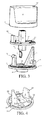
- the light-emitting knob assembly includes a knob 1 and a light guide member 2, which are fixed together in an engaging manner, as shown in FIG. 2 .
- the knob 1 includes a housing 11 and a bearing frame 12 fixed in the housing 11 in an embedding manner. Specifically, the housing 11 and the bearing frame 12 are fixed together by means of fusion welding. A top wall of the housing 11 of the knob 1 is provided with a through hole 112, and a side wall 111 of the housing 11 of the knob 1 is provided with a notch.
- the bearing frame 12 includes a rotating shaft receiving portion 121, two openings 123 and bearing portions 122 separately disposed at the openings 123.
- the light guide member 2 is fixed on the knob 1 in an engaging manner after the knob 1 is assembled (that is, after the housing 11 and the bearing frame 12 are fixed together).
- the light guide member 2 is integrally formed by using a mixed material of polycarbonate (namely, PC) and a light diffusing agent.
- the light guide member 2 includes a translucent ring 21 and a protruding portion 22.
- a hollow portion 212 for the rotating shaft receiving portion 121 to pass through in an up-to-down manner is disposed in the middle of the translucent ring 21.
- the protruding portion 22 is disposed on the translucent ring 21, and the volume of the protruding portion 22 gradually dwindles in a direction away from the light source 5.
- the protruding portion 22 is further provided with a translucent sheet 24 and two barbs 23, as shown in FIG. 4 to FIG. 6 .
- the translucent ring 21 is further provided with a separate barb 23, and the separate barb 23 and the protruding portion 22 are oppositely disposed and are spaced by the hollow portion 212.
- One of the openings 123 of the bearing frame 12 is used for the protruding portion 22 to pass through.
- the two barbs 23 of the protruding portion 22 move to the opening 123, under the action of an external force, the two barbs 23 of the protruding portion 22 extrude an edge encircling the opening 123, so that elastic deformation occurs to the edge encircling the opening 123, and then the two barbs 23 of the protruding portion 22 pass through the opening 123. After the two barbs 23 pass through the opening 123, the edge encircling the opening 123 recovers from the deformation. At this time, the two barbs 23 of the protruding portion 22 are put on the bearing portion 122 at the opening 123, and the two barbs 23 of the protruding portion 22 are incapable of exiting from the opening 123 in the case of no external force.
- the other opening 123 of the bearing frame 12 is used for the separate barb 23 to pass through.
- the separate barb 23 moves to the opening 123, the separate barb 23 extrudes an edge encircling the opening 123, and under the action of an external force, elastic deformation occurs to the separate barb 23, so that the separate barb 23 passes through the opening 123 and is put on the bearing portion 122 at the opening 123.
- the separate barb 23 has recovered from the deformation at this time and the separate barb 23 is incapable of exiting from the opening 123 in the case of no external force.
- the assembly and fixation of the light guide member 2 and the knob 1 are completed at this time, as shown in FIG. 10 and FIG. 11 .
- a tail end of the protruding portion 22 is placed into the through hole 112 of the housing 11 of the knob 1 to form a translucent point 221 for light transmission.
- the translucent point 221 is a frosted surface.
- the translucent sheet 24 is placed into the notch at this time. As shown in FIG. 2 and FIG. 10 , the translucent sheet 24 also is a frosted surface.
- the translucent ring 21 is located at the bottom of the knob 1, and a side wall 211 of the translucent ring 21 is smoothly connected to the side wall 111 of the knob 1, as shown in FIG. 2 , FIG. 10 and FIG. 11 .
- the side wall 211 of the translucent ring 21 is used as a translucent surface, and the translucent surface is a frosted surface.
- One end of the hollow portion 212 is provided with a light receiving surface 213, and the other end is provided with a chamfer 214.
- the chamfer 214 is used for partially reflecting light entering from the light receiving surface 213 towards the side wall 211 of the translucent ring 21.
- the hollow portion 212 extends in a direction away from the chamfer 214 to form a hollow cylinder portion 215, and the light receiving surface 213 is disposed at a tip of the cylinder portion 215, as shown in FIG. 6 .
- an extension direction of the cylinder portion 215 is opposite to an extension direction of the protruding portion 22.
- a bottom wall of the translucent ring 21 is a light shading surface 216, as shown in FIG. 6 , and the light shading surface 216 is a smooth surface.
- the light source 5 includes a hook 51, a lampshade 52, and an LED lamp 53, as shown in FIG. 1 , FIG. 8 , FIG. 9 and FIG. 11 .
- the LED lamp 53 is disposed around the rotating shaft 31, and the LED lamp 53 is provided with the lampshade 52 to protect the LED lamp 53, where the lampshade 52 is also disposed around the rotating shaft 31.
- a projecting direction of light emitted from the LED lamp 53 is parallel with an axis of the rotating shaft 31; therefore, the light emitted from the LED lamp 53 perpendicularly enters the light receiving surface 213.
- the light source 5 is fixed on the gas valve 3 in an engaging manner by using the hook 51.
- an engaging process deformation occurs to the hook 51 under the action of an external force, so that the light source 5 is fixed on the gas valve 3 in an engaging manner (an engaging principle is the same as a principle of engaging fixation between the light guide member 2 and the knob 1).
- an engaging principle is the same as a principle of engaging fixation between the light guide member 2 and the knob 1).
- the hook 51 recovers from the deformation at this time, and the hook 51 cannot be detached from the gas valve 3 if no external force is exerted.
- the light guide member may also be integrally formed by using another light-conductive material such as polycarbonate (namely, PC) or acrylic.
- another available engaging fixation structure may also be used to implement the engaging fixation.
- the engaging fixation is implemented by elastic deformation of one of the members, it is feasible to reverse their roles and implement the engaging fixation by making elastic deformation occur to the other one; and in addition, it is also feasible to implement the engaging fixation by making elastic deformation occur to both members for cooperating to implement the engaging fixation.
Landscapes
- Engineering & Computer Science (AREA)
- Chemical & Material Sciences (AREA)
- Combustion & Propulsion (AREA)
- Mechanical Engineering (AREA)
- General Engineering & Computer Science (AREA)
- Physics & Mathematics (AREA)
- General Physics & Mathematics (AREA)
- Automation & Control Theory (AREA)
- Rotary Switch, Piano Key Switch, And Lever Switch (AREA)
- Cookers (AREA)
Abstract
Description
- The present technical solution relates to the field of cooking appliances and the field of light-emitting knob assemblies for cooking appliances.
- A knob that has a light-emitting function and is used for an existing cooking appliance generally has a complicated assembly structure, thereby causing a low assembly efficiency. In addition, the knob that has the light-emitting function and is used for the existing cooking appliance also has a less diversified light guide structure and lacks an improvement in structure.
- Unless supported by enough evidences, the prior art described herein does not mean that it is publicly known to persons of ordinary skill in the art to which the present invention relates before the filing date of the present application.
- A primary objective of the present technical solution is to propose a new improvement for a cooking appliance and a light-emitting knob assembly thereof.
- A light-emitting knob assembly for a cooking appliance proposed by the present technical solution includes: a knob and a light guide member, where the light guide member is fixed on the knob in an engaging manner after the knob is assembled. Herein, the "engaging manner" should be understood as any connection solution of implementing the connection and fixation by using elasticity of a connecting piece, which can be obviously conceived of and applied to the present technical solution by a person of ordinary skill in the art on the basis of this specification, the prior art and common general knowledge. By using the present technical solution, the assembly efficiency can be improved.
- Optionally, the light guide member includes a translucent ring, and a side wall of the translucent ring is used as a translucent surface; and the translucent ring is located at the bottom of the knob, and the side wall of the translucent ring is smoothly connected to a side wall of the knob. The present technical solution proposes an entirely new structure of a light-emitting knob assembly for a cooking appliance, which not only helps to improve the assembly efficiency but also helps to improve an esthetic feeling of the appearance of the light-emitting knob assembly.
- Optionally, the knob includes a rotating shaft receiving portion; the light guide member includes a translucent ring, and the translucent ring is provided with a hollow portion for the rotating shaft receiving portion to pass through; one end of the hollow portion is provided with a light receiving surface, and the other end is provided with a chamfer; and the chamfer is used for at least partially reflecting light entering from the light receiving surface. The chamfer is used for changing a transmission direction of light entering from the light receiving surface, which helps to implement diversified modeling of the light guide member.
- Optionally, a side wall of the translucent ring is used as a translucent surface; the translucent ring is located at the bottom of the knob, and the side wall of the translucent ring is smoothly connected to a side wall of the knob; the hollow portion extends in a direction away from the chamfer to form a hollow cylinder portion, and the light receiving surface is disposed at a tip of the cylinder portion; and the chamfer is used for at least partially reflecting light entering from the light receiving surface towards the side wall of the translucent ring. The chamfer is used for changing a transmission direction of light entering from the light receiving surface, making it possible that the light receiving surface is disposed on the side wall of the translucent ring in a structure according to the present technical solution.
- Optionally, the light guide member includes a translucent surface; and the translucent surface is a frosted surface. By using a frosted surface, the translucent surface can achieve an optimal light transmission effect.
- Optionally, the light guide member includes a light shading surface; and the light shading surface is a smooth surface. The light shading surface is used for preventing light from getting out of the light guide member from the light shading surface or reducing the possibility. By using a smooth surface, the light shading surface can achieve an optimal light shading effect.
- Optionally, the light guide member is integrally formed by using any one of the following materials:
- polycarbonate,
- acrylic, and
- a mixed material of polycarbonate and a light diffusing agent. By using the materials, it can be ensured that the light guide member has an optimal light guide performance. Optionally, the knob includes a housing and a bearing frame fixed in the housing in an embedding manner; and the bearing frame is provided with an engaging member used for implementing engaging fixation.
- Optionally, the light guide member includes a protruding portion; the volume of the protruding portion gradually dwindles in a direction away from a light source; and the bottom of the knob is provided with an opening for the protruding portion to pass through. Because the volume of the protruding portion gradually dwindles in the direction away from the light source, the protruding portion can achieve an optimal light guide effect. It should be noted herein that "the volume gradually dwindles" is broadly understood, that is, it may literally mean that the volume gradually dwindles, and it may also mean that the overall volume shows a trend of gradually dwindling.
- Optionally, a top wall of the knob is provided with a through hole; and a tail end of the protruding portion is placed into the through hole to form a translucent point. It should be noted herein that after the tail end of the protruding portion is placed into the through hole, the translucent point is formed, and at the same time it helps to fix the light guide member.
- Optionally, the light guide member includes a barb used for implementing the engaging fixation; and the knob is provided with a bearing portion for the barb to be put on.
- Optionally, the barb is disposed on the protruding portion, which helps to simplify a structure.
- Optionally, the protruding portion includes a translucent sheet; the side wall of the knob is provided with a notch; and the translucent sheet is placed into the notch. It should be noted herein that the translucent sheet is placed into the notch for light transmission, and it also helps to fix the light guide member at the same time.
- The present technical solution further proposes a cooking appliance provided with the light-emitting knob assembly according to any item described above. By using the present technical solution, the assembly efficiency can be improved. Specifically, the cooking appliance may be a gas cooking appliance, an induction cooktop, a combined cooking appliance of a gas cooking appliance and an induction cooktop, or a cooking appliance of another type which can use the present technical solution, such as a resistance wire heating cooking appliance, an electrothermal film heating cooking appliance or a fuel cooking appliance.
- Optionally, the cooking appliance includes a light source and a gas valve, and the gas valve includes a rotating shaft; and the light source is fixed on the gas valve in an engaging manner. Herein, the "engaging manner" should be understood as any connection solution of implementing the connection and fixation by using elasticity of a connecting piece, which can be obviously conceived of and applied to the present technical solution by a person of ordinary skill in the art on the basis of this specification, the prior art and common general knowledge, which helps to further improve the assembly efficiency.
- It should be noted herein that the directional expression such as "bottom of the knob" in the present technical solution is described based on a common mounting state of the cooking appliance in the case of no special instruction.
- The foregoing technical solution content of the present technical solution is not to describe all possible implementation manners of the present technical solution. In the entire application, many examples are given for providing a guide, and these examples can be used in various feasible combinations.
- The following accompanying drawings only make exemplary descriptions and illustrations for the present technical solution, instead of limiting the scope of the present technical solution, and wherein:
- FIG. 1
- is an exploded view of a local structure of a gas cooking appliance according to an embodiment of the present technical solution;
- FIG. 2
- is a schematic structural diagram of a light-emitting knob assembly of a gas cooking appliance according to an embodiment of the present technical solution;
- FIG. 3
- is an exploded view of the light-emitting knob assembly shown in
FIG. 2 ; - FIG. 4
- is a schematic structural diagram of a light guide member of the light-emitting knob assembly shown in
FIG. 2 ; - FIG. 5
- is another schematic structural diagram of a light guide member of the light-emitting knob assembly shown in
FIG. 2 ; - FIG. 6
- is still another schematic structural diagram of a light guide member of the light-emitting knob assembly shown in
FIG. 2 ; - FIG. 7
- is a cross-sectional view of a light guide member of the light-emitting knob assembly shown in
FIG. 2 ; - FIG. 8
- is an assembly rendering of a gas valve and a light source of a gas cooking appliance according to an embodiment of the present technical solution;
- FIG. 9
- is an exploded view of another local structure of a gas cooking appliance according to an embodiment of the present technical solution;
- FIG. 10
- is a cross-sectional view of a local structure of a gas cooking appliance according to an embodiment of the present technical solution; and
- FIG. 11
- is a cross-sectional view of another local structure of a gas cooking appliance according to an embodiment of the present technical solution.
- In order to make the objectives, solutions, beneficial effects of the present technical solution clearer, the present technical solution is further described below by using preferred embodiments with reference to the accompanying drawings.
- The present technical solution proposes an embodiment of a gas cooking appliance, and relevant structures of the gas cooking appliance are as shown in
FIG. 1 to FIG. 11 . The gas cooking appliance includes a light-emitting knob assembly, a light source 5, a panel 6, an elastic piece 4, a sealingring 7 and agas valve 3. Thegas valve 3 includes arotating shaft 31, and therotating shaft 31 is used for controlling thegas valve 3. As shown inFIG. 10 and FIG. 11 , the panel 6 is provided with a mounting hole, which is used for therotating shaft 31 to pass through. The elastic piece 4 is used for enabling the rotatingshaft 31 and the light-emitting knob assembly to be fixed together by extrusion. The sealingring 7 is mounted at the mounting hole of the panel 6 to prevent a fluid dripping on the panel 6 from flowing to a place below the panel 6 through the mounting hole. It should be noted that the sealingring 7 can also function to shade light to some extent. - The light-emitting knob assembly includes a knob 1 and a
light guide member 2, which are fixed together in an engaging manner, as shown inFIG. 2 . The knob 1 includes ahousing 11 and abearing frame 12 fixed in thehousing 11 in an embedding manner. Specifically, thehousing 11 and thebearing frame 12 are fixed together by means of fusion welding. A top wall of thehousing 11 of the knob 1 is provided with a throughhole 112, and aside wall 111 of thehousing 11 of the knob 1 is provided with a notch. The bearingframe 12 includes a rotatingshaft receiving portion 121, twoopenings 123 and bearingportions 122 separately disposed at theopenings 123. - The
light guide member 2 is fixed on the knob 1 in an engaging manner after the knob 1 is assembled (that is, after thehousing 11 and thebearing frame 12 are fixed together). Specifically, thelight guide member 2 is integrally formed by using a mixed material of polycarbonate (namely, PC) and a light diffusing agent. Thelight guide member 2 includes atranslucent ring 21 and a protrudingportion 22. Ahollow portion 212 for the rotatingshaft receiving portion 121 to pass through in an up-to-down manner is disposed in the middle of thetranslucent ring 21. The protrudingportion 22 is disposed on thetranslucent ring 21, and the volume of the protrudingportion 22 gradually dwindles in a direction away from the light source 5. The protrudingportion 22 is further provided with atranslucent sheet 24 and twobarbs 23, as shown inFIG. 4 to FIG. 6 . Thetranslucent ring 21 is further provided with aseparate barb 23, and theseparate barb 23 and the protrudingportion 22 are oppositely disposed and are spaced by thehollow portion 212. One of theopenings 123 of the bearingframe 12 is used for the protrudingportion 22 to pass through. When the twobarbs 23 of the protrudingportion 22 move to theopening 123, under the action of an external force, the twobarbs 23 of the protrudingportion 22 extrude an edge encircling theopening 123, so that elastic deformation occurs to the edge encircling theopening 123, and then the twobarbs 23 of the protrudingportion 22 pass through theopening 123. After the twobarbs 23 pass through theopening 123, the edge encircling theopening 123 recovers from the deformation. At this time, the twobarbs 23 of the protrudingportion 22 are put on the bearingportion 122 at theopening 123, and the twobarbs 23 of the protrudingportion 22 are incapable of exiting from theopening 123 in the case of no external force. In fact, the assembly and fixation of thelight guide member 2 and the knob 1 are completed at this time, as shown inFIG. 10 and FIG. 11 . Theother opening 123 of the bearingframe 12 is used for theseparate barb 23 to pass through. Specifically, when theseparate barb 23 moves to theopening 123, theseparate barb 23 extrudes an edge encircling theopening 123, and under the action of an external force, elastic deformation occurs to theseparate barb 23, so that theseparate barb 23 passes through theopening 123 and is put on the bearingportion 122 at theopening 123. In addition, theseparate barb 23 has recovered from the deformation at this time and theseparate barb 23 is incapable of exiting from theopening 123 in the case of no external force. In fact, the assembly and fixation of thelight guide member 2 and the knob 1 are completed at this time, as shown inFIG. 10 and FIG. 11 . At this time, a tail end of the protrudingportion 22 is placed into the throughhole 112 of thehousing 11 of the knob 1 to form atranslucent point 221 for light transmission. As shown inFIG. 2 andFIG. 10 , thetranslucent point 221 is a frosted surface. In addition, thetranslucent sheet 24 is placed into the notch at this time. As shown inFIG. 2 andFIG. 10 , thetranslucent sheet 24 also is a frosted surface. - When the assembly and fixation of the
light guide member 2 and the knob 1 are completed, thetranslucent ring 21 is located at the bottom of the knob 1, and aside wall 211 of thetranslucent ring 21 is smoothly connected to theside wall 111 of the knob 1, as shown inFIG. 2 ,FIG. 10 and FIG. 11 . Theside wall 211 of thetranslucent ring 21 is used as a translucent surface, and the translucent surface is a frosted surface. One end of thehollow portion 212 is provided with alight receiving surface 213, and the other end is provided with achamfer 214. Thechamfer 214 is used for partially reflecting light entering from thelight receiving surface 213 towards theside wall 211 of thetranslucent ring 21. - The
hollow portion 212 extends in a direction away from thechamfer 214 to form ahollow cylinder portion 215, and thelight receiving surface 213 is disposed at a tip of thecylinder portion 215, as shown inFIG. 6 . In addition, an extension direction of thecylinder portion 215 is opposite to an extension direction of the protrudingportion 22. A bottom wall of thetranslucent ring 21 is alight shading surface 216, as shown inFIG. 6 , and thelight shading surface 216 is a smooth surface. - The light source 5 includes a
hook 51, alampshade 52, and anLED lamp 53, as shown inFIG. 1 ,FIG. 8 ,FIG. 9 andFIG. 11 . TheLED lamp 53 is disposed around the rotatingshaft 31, and theLED lamp 53 is provided with thelampshade 52 to protect theLED lamp 53, where thelampshade 52 is also disposed around the rotatingshaft 31. A projecting direction of light emitted from theLED lamp 53 is parallel with an axis of therotating shaft 31; therefore, the light emitted from theLED lamp 53 perpendicularly enters thelight receiving surface 213. The light source 5 is fixed on thegas valve 3 in an engaging manner by using thehook 51. Specifically, in an engaging process, deformation occurs to thehook 51 under the action of an external force, so that the light source 5 is fixed on thegas valve 3 in an engaging manner (an engaging principle is the same as a principle of engaging fixation between thelight guide member 2 and the knob 1). As shown inFIG. 8, FIG. 9 andFIG. 11 , thehook 51 recovers from the deformation at this time, and thehook 51 cannot be detached from thegas valve 3 if no external force is exerted. - The above is merely a preferred embodiment of the present technical solution, and other embodiments may be obtained by performing additions, deletions, modifications, or replacements on some technical features. For example, the light guide member may also be integrally formed by using another light-conductive material such as polycarbonate (namely, PC) or acrylic. For another example, another available engaging fixation structure may also be used to implement the engaging fixation. For still another example, with regard to two members for cooperating to implement the engaging fixation, if the engaging fixation is implemented by elastic deformation of one of the members, it is feasible to reverse their roles and implement the engaging fixation by making elastic deformation occur to the other one; and in addition, it is also feasible to implement the engaging fixation by making elastic deformation occur to both members for cooperating to implement the engaging fixation.
- It should be additionally noted that, it should be understood that the present technical solution covers all possible implementations determined by the claims of the present technical solution in combination with the disclosure of the specification, instead of being limited to the embodiment described above. Therefore, any simple modification, equivalent change, and modification made according to the technical essence of the present technical solution without departing from the content of the present technical solution shall fall within the protection scope of the present technical solution. It should be particularly noted that any inferior application on the basis of the present technical solution also belongs to the protection scope of the present technical solution.
-
- 1.
- knob;
- 11.
- housing;
- 111.
- side wall of the knob;
- 112.
- through hole;
- 12.
- bearing frame;
- 121.
- rotating shaft receiving portion;
- 122.
- bearing portion;
- 123.
- opening;
- 2.
- light guide member;
- 21.
- translucent ring;
- 211.
- side wall of the translucent ring;
- 212.
- hollow portion;
- 213.
- light receiving surface;
- 214.
- chamfer;
- 215.
- cylinder portion;
- 216.
- light shading surface;
- 22.
- protruding portion;
- 221.
- translucent point;
- 23.
- barb;
- 24.
- translucent sheet;
- 3.
- gas valve;
- 31.
- rotating shaft
- 4.
- elastic piece;
- 5.
- light source;
- 51.
- hook;
- 52.
- lampshade;
- 53.
- LED lamp;
- 6.
- panel;
- 7.
- sealing ring
Claims (15)
- A light-emitting knob assembly for a cooking appliance, characterized by:comprising a knob (1) and a light guide member (2), whereinthe light guide member (2) is fixed on the knob (1) in an engaging manner after the knob (1) is assembled.
- The light-emitting knob assembly according to claim 1, characterized in that:the light guide member (2) comprises a translucent ring (21), and a side wall (211) of the translucent ring (21) is used as a translucent surface; and the translucent ring (21) is located at the bottom of the knob (1), and the side wall (211) of the translucent ring (21) is smoothly connected to a side wall (111) of the knob (1).
- The light-emitting knob assembly according to claim 1, characterized in that:the knob (1) comprises a rotating shaft receiving portion (121);the light guide member (2) comprises a translucent ring (21), and the translucent ring (21) is provided with a hollow portion (212) for the rotating shaft receiving portion (121) to pass through; one end of the hollow portion (212) is provided with a light receiving surface (213), and the other end is provided with a chamfer (214);and the chamfer (214) is used for at least partially reflecting light entering from the light receiving surface (213).
- The light-emitting knob assembly according to claim 3, characterized in that:a side wall (211) of the translucent ring (21) is used as a translucent surface;the translucent ring (21) is located at the bottom of the knob (1), and the side wall (211) of the translucent ring (21) is smoothly connected to a side wall (111) of the knob (1);the hollow portion (212) extends in a direction away from the chamfer (214) to form a hollow cylinder portion (215), and the light receiving surface (213) is disposed at a tip of the cylinder portion (215); andthe chamfer (214) is used for at least partially reflecting light entering from the light receiving surface (213) towards the side wall (211) of the translucent ring (21).
- The light-emitting knob assembly according to claim 1, characterized in that:the light guide member (2) comprises a translucent surface; andthe translucent surface is a frosted surface.
- The light-emitting knob assembly according to claim 1, characterized in that:the light guide member (2) comprises a light shading surface (216); andthe light shading surface (216) is a smooth surface.
- The light-emitting knob assembly according to claim 1, characterized in that:the light guide member (2) is integrally formed by using any one of the following materials:polycarbonate,acrylic, anda mixed material of polycarbonate and a light diffusing agent.
- The light-emitting knob assembly according to claim 1, characterized in that:the knob (1) comprises a housing (11) and a bearing frame (12) fixed in the housing (11) in an embedding manner; andthe bearing frame (12) is provided with an engaging member used for implementing engaging fixation.
- The light-emitting knob assembly according to any one of the forgoing claims, characterized in that:the light guide member (2) comprises a protruding portion (22);the volume of the protruding portion (22) gradually dwindles in a direction away from a light source (5); andthe bottom of the knob (1) is provided with an opening (123) for the protruding portion (22) to pass through.
- The light-emitting knob assembly according to claim 9, characterized in that:a top wall of the knob (1) is provided with a through hole (112); anda tail end of the protruding portion (22) is placed into the through hole (112) to form a translucent point (221).
- The light-emitting knob assembly according to claim 9, characterized in that:the light guide member (2) comprises a barb (23) used for implementing the engaging fixation; andthe knob (1) is provided with a bearing portion (122) for the barb (23) to be put on.
- The light-emitting knob assembly according to claim 11, characterized in that:the barb (23) is disposed on the protruding portion (22).
- The light-emitting knob assembly according to claim 9, characterized in that:the protruding portion (22) comprises a translucent sheet (24);the side wall (111) of the knob (1) is provided with a notch; andthe translucent sheet (24) is placed into the notch.
- A cooking appliance, characterized in that the cooking appliance is provided with the light-emitting knob assembly according to any one of the forgoing claims.
- The cooking appliance according to claim 14, characterized in that:the cooking appliance comprises a light source (5) and a gas valve (3), and the gas valve (3) comprises a rotating shaft (31); andthe light source (5) is fixed on the gas valve (3) in an engaging manner.
Applications Claiming Priority (1)
| Application Number | Priority Date | Filing Date | Title |
|---|---|---|---|
| CN201420147252.2U CN204063153U (en) | 2014-03-28 | 2014-03-28 | Kitchen range and luminous knob assembly thereof |
Publications (2)
| Publication Number | Publication Date |
|---|---|
| EP2924534A2 true EP2924534A2 (en) | 2015-09-30 |
| EP2924534A3 EP2924534A3 (en) | 2016-07-13 |
Family
ID=52204654
Family Applications (1)
| Application Number | Title | Priority Date | Filing Date |
|---|---|---|---|
| EP15157190.8A Withdrawn EP2924534A3 (en) | 2014-03-28 | 2015-03-02 | Cooking appliance and light-emitting knob assembly thereof |
Country Status (2)
| Country | Link |
|---|---|
| EP (1) | EP2924534A3 (en) |
| CN (1) | CN204063153U (en) |
Cited By (4)
| Publication number | Priority date | Publication date | Assignee | Title |
|---|---|---|---|---|
| CN108369875A (en) * | 2015-12-30 | 2018-08-03 | 三星电子株式会社 | Switch module and cooker including it |
| CN113703516A (en) * | 2021-08-03 | 2021-11-26 | 奇瑞汽车股份有限公司 | Volume adjusting knob |
| WO2022069214A1 (en) * | 2020-09-30 | 2022-04-07 | BSH Hausgeräte GmbH | Control knob, control system and household appliance |
| WO2025228659A1 (en) * | 2024-04-30 | 2025-11-06 | BSH Hausgeräte GmbH | Operating element, a control system and an electrical household appliance |
Families Citing this family (5)
| Publication number | Priority date | Publication date | Assignee | Title |
|---|---|---|---|---|
| TWI546501B (en) | 2015-04-28 | 2016-08-21 | 太琦科技股份有限公司 | Light-emitting knob assembly |
| US10409314B2 (en) | 2015-09-30 | 2019-09-10 | Haier Us Appliance Solutions, Inc. | Integrated housing for components of a cooking appliance |
| IT201700048993A1 (en) * | 2017-05-05 | 2018-11-05 | De Longhi Appliances Srl | SELECTOR DEVICE FOR APPLIANCES AND HOUSEHOLD APPLIANCES INCLUDING THE SELECTOR DEVICE |
| CN111947189A (en) * | 2020-08-25 | 2020-11-17 | 杭州老板电器股份有限公司 | Locating component and kitchen range |
| US12140319B2 (en) * | 2023-02-27 | 2024-11-12 | Whirlpool Corporation | Eccentric knob assembly for gas appliances |
Family Cites Families (3)
| Publication number | Priority date | Publication date | Assignee | Title |
|---|---|---|---|---|
| DE2035719C3 (en) * | 1970-07-18 | 1981-11-12 | Robert Bosch Gmbh, 7000 Stuttgart | Knob |
| DE102010031405A1 (en) * | 2010-07-15 | 2012-01-19 | E.G.O. Elektro-Gerätebau GmbH | Holding device for an operating device |
| TWI437599B (en) * | 2011-12-21 | 2014-05-11 | Wistron Neweb Corp | Concentricly illuminated knob structure and acoustic structure with knob structure |
-
2014
- 2014-03-28 CN CN201420147252.2U patent/CN204063153U/en not_active Expired - Lifetime
-
2015
- 2015-03-02 EP EP15157190.8A patent/EP2924534A3/en not_active Withdrawn
Non-Patent Citations (1)
| Title |
|---|
| None |
Cited By (7)
| Publication number | Priority date | Publication date | Assignee | Title |
|---|---|---|---|---|
| CN108369875A (en) * | 2015-12-30 | 2018-08-03 | 三星电子株式会社 | Switch module and cooker including it |
| EP3373316A4 (en) * | 2015-12-30 | 2018-12-26 | Samsung Electronics Co., Ltd. | Switch assembly and cooking apparatus including same |
| US10458656B2 (en) | 2015-12-30 | 2019-10-29 | Samsung Electronics Co., Ltd. | Switch assembly and cooking apparatus having the same |
| WO2022069214A1 (en) * | 2020-09-30 | 2022-04-07 | BSH Hausgeräte GmbH | Control knob, control system and household appliance |
| CN113703516A (en) * | 2021-08-03 | 2021-11-26 | 奇瑞汽车股份有限公司 | Volume adjusting knob |
| CN113703516B (en) * | 2021-08-03 | 2022-06-10 | 奇瑞汽车股份有限公司 | Volume adjusting knob |
| WO2025228659A1 (en) * | 2024-04-30 | 2025-11-06 | BSH Hausgeräte GmbH | Operating element, a control system and an electrical household appliance |
Also Published As
| Publication number | Publication date |
|---|---|
| EP2924534A3 (en) | 2016-07-13 |
| CN204063153U (en) | 2014-12-31 |
Similar Documents
| Publication | Publication Date | Title |
|---|---|---|
| USD876466S1 (en) | Display screen with graphical user interface | |
| CN204063153U (en) | Kitchen range and luminous knob assembly thereof | |
| USD921024S1 (en) | Display screen with graphical user interface | |
| WO2008042805A3 (en) | Method and device for displaying cooking-related information on a cooktop | |
| USD882617S1 (en) | Display screen or portion thereof with a graphical user interface | |
| WO2015026879A3 (en) | Light emitting diode light panels | |
| CN203336493U (en) | Frame of lighting lamp | |
| CN102032525A (en) | Lampshade for energy-saving lamp | |
| WO2009005314A3 (en) | Shade exchangeable led bulb | |
| DE602007002480D1 (en) | LIGHT AND LAMELLAR GRID FOR THIS | |
| EP2131382B8 (en) | Single socket lamp | |
| USD927505S1 (en) | Display screen or portion thereof with graphical user interface | |
| CN201964322U (en) | LED lampshade | |
| CN203036282U (en) | Sleep lamp | |
| CN204403945U (en) | A kind of Ultrathin LED panel light | |
| CN201547671U (en) | Glareproof light transmitting cover | |
| CN205778255U (en) | A kind of energy-saving glass | |
| CN204592931U (en) | A kind of children's illuminating lamp | |
| CN204586449U (en) | A kind of rotating shaft of sunshading board with anti-drop function | |
| CN209587967U (en) | A kind of LED lamp shade clamping fastener | |
| CN201611036U (en) | Cold light lamp | |
| CN202120531U (en) | Face cover structure of light-emitting diode (LED) display unit | |
| CN204026598U (en) | A kind of LED panel light cooling ring structure | |
| CN208516690U (en) | LED elevator arrives at a station lamp | |
| CN205849240U (en) | Display module and electric cooker |
Legal Events
| Date | Code | Title | Description |
|---|---|---|---|
| PUAI | Public reference made under article 153(3) epc to a published international application that has entered the european phase |
Free format text: ORIGINAL CODE: 0009012 |
|
| AK | Designated contracting states |
Kind code of ref document: A2 Designated state(s): AL AT BE BG CH CY CZ DE DK EE ES FI FR GB GR HR HU IE IS IT LI LT LU LV MC MK MT NL NO PL PT RO RS SE SI SK SM TR |
|
| AX | Request for extension of the european patent |
Extension state: BA ME |
|
| PUAL | Search report despatched |
Free format text: ORIGINAL CODE: 0009013 |
|
| AK | Designated contracting states |
Kind code of ref document: A3 Designated state(s): AL AT BE BG CH CY CZ DE DK EE ES FI FR GB GR HR HU IE IS IT LI LT LU LV MC MK MT NL NO PL PT RO RS SE SI SK SM TR |
|
| AX | Request for extension of the european patent |
Extension state: BA ME |
|
| RIC1 | Information provided on ipc code assigned before grant |
Ipc: G05G 1/10 20060101AFI20160608BHEP |
|
| 17P | Request for examination filed |
Effective date: 20170113 |
|
| RBV | Designated contracting states (corrected) |
Designated state(s): AL AT BE BG CH CY CZ DE DK EE ES FI FR GB GR HR HU IE IS IT LI LT LU LV MC MK MT NL NO PL PT RO RS SE SI SK SM TR |
|
| RIC1 | Information provided on ipc code assigned before grant |
Ipc: F24C 3/12 20060101ALI20190228BHEP Ipc: G05G 1/10 20060101AFI20190228BHEP |
|
| GRAP | Despatch of communication of intention to grant a patent |
Free format text: ORIGINAL CODE: EPIDOSNIGR1 |
|
| INTG | Intention to grant announced |
Effective date: 20190415 |
|
| STAA | Information on the status of an ep patent application or granted ep patent |
Free format text: STATUS: THE APPLICATION IS DEEMED TO BE WITHDRAWN |
|
| 18D | Application deemed to be withdrawn |
Effective date: 20190827 |