EP2924420A1 - Fluoroscopic image density correction method, non-destructive inspection method, and image processing device - Google Patents
Fluoroscopic image density correction method, non-destructive inspection method, and image processing device Download PDFInfo
- Publication number
- EP2924420A1 EP2924420A1 EP13856082.6A EP13856082A EP2924420A1 EP 2924420 A1 EP2924420 A1 EP 2924420A1 EP 13856082 A EP13856082 A EP 13856082A EP 2924420 A1 EP2924420 A1 EP 2924420A1
- Authority
- EP
- European Patent Office
- Prior art keywords
- inspection
- density
- fluoroscopic image
- weld
- basis
- Prior art date
- Legal status (The legal status is an assumption and is not a legal conclusion. Google has not performed a legal analysis and makes no representation as to the accuracy of the status listed.)
- Ceased
Links
Images




Classifications
-
- G—PHYSICS
- G06—COMPUTING OR CALCULATING; COUNTING
- G06T—IMAGE DATA PROCESSING OR GENERATION, IN GENERAL
- G06T7/00—Image analysis
- G06T7/0002—Inspection of images, e.g. flaw detection
- G06T7/0004—Industrial image inspection
- G06T7/001—Industrial image inspection using an image reference approach
-
- G—PHYSICS
- G01—MEASURING; TESTING
- G01B—MEASURING LENGTH, THICKNESS OR SIMILAR LINEAR DIMENSIONS; MEASURING ANGLES; MEASURING AREAS; MEASURING IRREGULARITIES OF SURFACES OR CONTOURS
- G01B15/00—Measuring arrangements characterised by the use of electromagnetic waves or particle radiation, e.g. by the use of microwaves, X-rays, gamma rays or electrons
- G01B15/02—Measuring arrangements characterised by the use of electromagnetic waves or particle radiation, e.g. by the use of microwaves, X-rays, gamma rays or electrons for measuring thickness
- G01B15/025—Measuring arrangements characterised by the use of electromagnetic waves or particle radiation, e.g. by the use of microwaves, X-rays, gamma rays or electrons for measuring thickness by measuring absorption
-
- G—PHYSICS
- G01—MEASURING; TESTING
- G01N—INVESTIGATING OR ANALYSING MATERIALS BY DETERMINING THEIR CHEMICAL OR PHYSICAL PROPERTIES
- G01N23/00—Investigating or analysing materials by the use of wave or particle radiation, e.g. X-rays or neutrons, not covered by groups G01N3/00 – G01N17/00, G01N21/00 or G01N22/00
- G01N23/02—Investigating or analysing materials by the use of wave or particle radiation, e.g. X-rays or neutrons, not covered by groups G01N3/00 – G01N17/00, G01N21/00 or G01N22/00 by transmitting the radiation through the material
- G01N23/04—Investigating or analysing materials by the use of wave or particle radiation, e.g. X-rays or neutrons, not covered by groups G01N3/00 – G01N17/00, G01N21/00 or G01N22/00 by transmitting the radiation through the material and forming images of the material
- G01N23/043—Investigating or analysing materials by the use of wave or particle radiation, e.g. X-rays or neutrons, not covered by groups G01N3/00 – G01N17/00, G01N21/00 or G01N22/00 by transmitting the radiation through the material and forming images of the material using fluoroscopic examination, with visual observation or video transmission of fluoroscopic images
-
- G—PHYSICS
- G06—COMPUTING OR CALCULATING; COUNTING
- G06T—IMAGE DATA PROCESSING OR GENERATION, IN GENERAL
- G06T7/00—Image analysis
- G06T7/70—Determining position or orientation of objects or cameras
- G06T7/73—Determining position or orientation of objects or cameras using feature-based methods
-
- G—PHYSICS
- G01—MEASURING; TESTING
- G01N—INVESTIGATING OR ANALYSING MATERIALS BY DETERMINING THEIR CHEMICAL OR PHYSICAL PROPERTIES
- G01N21/00—Investigating or analysing materials by the use of optical means, i.e. using sub-millimetre waves, infrared, visible or ultraviolet light
- G01N21/84—Systems specially adapted for particular applications
- G01N21/88—Investigating the presence of flaws or contamination
- G01N21/95—Investigating the presence of flaws or contamination characterised by the material or shape of the object to be examined
- G01N21/954—Inspecting the inner surface of hollow bodies, e.g. bores
- G01N2021/9548—Scanning the interior of a cylinder
-
- G—PHYSICS
- G01—MEASURING; TESTING
- G01N—INVESTIGATING OR ANALYSING MATERIALS BY DETERMINING THEIR CHEMICAL OR PHYSICAL PROPERTIES
- G01N2223/00—Investigating materials by wave or particle radiation
- G01N2223/40—Imaging
- G01N2223/401—Imaging image processing
-
- G—PHYSICS
- G01—MEASURING; TESTING
- G01N—INVESTIGATING OR ANALYSING MATERIALS BY DETERMINING THEIR CHEMICAL OR PHYSICAL PROPERTIES
- G01N2223/00—Investigating materials by wave or particle radiation
- G01N2223/60—Specific applications or type of materials
- G01N2223/601—Specific applications or type of materials density profile
-
- G—PHYSICS
- G01—MEASURING; TESTING
- G01N—INVESTIGATING OR ANALYSING MATERIALS BY DETERMINING THEIR CHEMICAL OR PHYSICAL PROPERTIES
- G01N2223/00—Investigating materials by wave or particle radiation
- G01N2223/60—Specific applications or type of materials
- G01N2223/628—Specific applications or type of materials tubes, pipes
-
- G—PHYSICS
- G01—MEASURING; TESTING
- G01N—INVESTIGATING OR ANALYSING MATERIALS BY DETERMINING THEIR CHEMICAL OR PHYSICAL PROPERTIES
- G01N2223/00—Investigating materials by wave or particle radiation
- G01N2223/60—Specific applications or type of materials
- G01N2223/629—Specific applications or type of materials welds, bonds, sealing compounds
-
- G—PHYSICS
- G06—COMPUTING OR CALCULATING; COUNTING
- G06T—IMAGE DATA PROCESSING OR GENERATION, IN GENERAL
- G06T2207/00—Indexing scheme for image analysis or image enhancement
- G06T2207/10—Image acquisition modality
- G06T2207/10064—Fluorescence image
-
- G—PHYSICS
- G06—COMPUTING OR CALCULATING; COUNTING
- G06T—IMAGE DATA PROCESSING OR GENERATION, IN GENERAL
- G06T2207/00—Indexing scheme for image analysis or image enhancement
- G06T2207/10—Image acquisition modality
- G06T2207/10116—X-ray image
- G06T2207/10121—Fluoroscopy
-
- G—PHYSICS
- G06—COMPUTING OR CALCULATING; COUNTING
- G06T—IMAGE DATA PROCESSING OR GENERATION, IN GENERAL
- G06T2207/00—Indexing scheme for image analysis or image enhancement
- G06T2207/30—Subject of image; Context of image processing
- G06T2207/30108—Industrial image inspection
- G06T2207/30136—Metal
-
- G—PHYSICS
- G06—COMPUTING OR CALCULATING; COUNTING
- G06T—IMAGE DATA PROCESSING OR GENERATION, IN GENERAL
- G06T2207/00—Indexing scheme for image analysis or image enhancement
- G06T2207/30—Subject of image; Context of image processing
- G06T2207/30108—Industrial image inspection
- G06T2207/30152—Solder
Definitions
- the present invention relates to a fluoroscopic image density correction method, a non-destructive inspection method, and an image processing device capable of non-destructively inspecting for defects of welded portions of pipes in a case of welding a plurality of pipes.
- the present invention relates to a fluoroscopic image density correction method, a non-destructive inspection method, and an image processing device capable of obtaining the same inspection results without dependency on the skill level of an inspector for identification in images even if density irregularities occur in a fluoroscopic image.
- non-destructive inspection is performed as follows. First, radiation, which originates from a radiation source and is transmitted through a welded portion of pipes, is detected by a sheet-like radiation detection medium. A fluoroscopic image, which is generated by the radiation detection medium, is read from the radiation detection medium by a dedicated scanner. The read fluoroscopic image is displayed on a display screen of a personal computer (hereinafter referred to as "PC"), and an inspector checks the image visually.
- PC personal computer
- an external diameter point and an inner diameter point of a pipe are detected by using a luminance profile in a direction intersecting with the pipe in a radiation fluoroscopic image of the pipe.
- a thickness of a test pipe is calculated through density comparison by performing radiographic imaging on a monitoring pipe of which a thickness is known and the test pipe of which the thickness is unknown at the same time.
- JP2005-037193A in non-destructive inspection, an inspection target is placed on a rotational base which rotates with predetermined angular displacement, and tomography is performed by radiation.
- an eccentricity of a central axis of rotation of the inspection target is set as a parameter, and the eccentricity, which is obtained when a sharpness of a fluoroscopic image (cross-section image) is at the maximum, is specified as an optimum eccentricity of the central axis of rotation.
- JP2003-190125A there is proposed image processing for facilitating comparative reading of a plurality of medical fluoroscopic images.
- a frequency distribution (histogram) of density values (signal values) in a reference fluoroscopic image is calculated, the density value which has the maximum frequency in the frequency distribution is calculated as a representative value, and image processing (density correction) is performed on the other fluoroscopic images such that the representative values of the other fluoroscopic images are adjusted to the representative value of the reference fluoroscopic image (paragraphs 0049 to 0055).
- JP2012-47569A the external diameter point and the inner diameter point of the pipe are detected by using the luminance profile in the direction intersecting with the pipe.
- density correction of the fluoroscopic image based on the luminance profile there is no description regarding density correction of the fluoroscopic image based on the luminance profile.
- the thickness of the test pipe is calculated through density comparison by performing radiographic imaging on the monitoring pipe of which the thickness is known and the test pipe of which the thickness is unknown at the same time.
- density correction of the fluoroscopic image based on the density profile.
- JP1986-274210A JP-S61-274210A
- scanning is performed on the reference pipe and the measurement target pipe under the same conditions.
- JP2005-037193A it is necessary to place the inspection target on the rotational base and capture a fluoroscopic image thereof. Thus, it is difficult to apply the inspection method to a case of imaging the welded portion of the installed pipe. Further, the number and the time period of imaging operations using radiation are restricted. Therefore, it is not realistic to perform imaging several times while changing the imaging conditions.
- JP2003-190125A there is proposed only a general density adjustment technique.
- the technique in density correction for medical fluoroscopic images of a human body section, the frequency distributions of density values of the fluoroscopic images are calculated, and the density values of one fluoroscopic image, which have the maximum frequencies, are adjusted to the density values of the other fluoroscopic images which have the maximum frequencies. Consequently, practically, even if such a density adjustment technique is applied to fluoroscopic images of a welded portion of the pipes by simply adjusting the density values in a specific region of one fluoroscopic image to the density values in a specific region of the other fluoroscopic images, typical density irregularities shown in the fluoroscopic image of the pipe are unlikely to be removed.
- the present invention has been made in consideration of such situations, and its object is to obtain the same inspection results without dependency on the skill level of an inspector for identification in images even if density irregularities occur in a fluoroscopic image of a welded portion of pipes when inspection or measurement is performed using the fluoroscopic image of the welded portion of the pipes.
- a fluoroscopic image density correction method including: acquiring a reference fluoroscopic image generated from a flexible radiation detection medium, which is disposed on an outer circumference of a reference pipe having a reference welded portion, when a radiation source is disposed on a central axis of the reference pipe and radiation originating from the radiation source is detected by the radiation detection medium; generating a reference density profile, which indicates a relationship between density values and coordinates on the reference fluoroscopic image in a direction along the outer circumference of the reference pipe, on the basis of the reference fluoroscopic image; acquiring a weld inspection fluoroscopic image generated from a flexible radiation detection medium, which is disposed on an outer circumference of an inspection target pipe, when a radiation source is disposed inside an inspection target pipe having an inspection target welded portion and radiation originating from the radiation source is detected by the radiation detection medium; generating a weld inspection density profile, which indicates a relationship between density values and coordinates on the weld
- the reference density profile which indicates a relationship between density values and coordinates in the direction along the outer circumference of the pipe
- the weld inspection density profile which indicates a relationship between density values and coordinates in the direction along the outer circumference of the pipe
- density irregularities in the direction along the outer circumference of the inspection target pipe are removed from the weld inspection fluoroscopic image through correction on the basis of the reference density profile and the weld inspection density profile. Therefore, it is possible to obtain the same inspection results without dependency on the skill level of an inspector for identification in images even if density irregularities occur in the weld inspection fluoroscopic image.
- a density profile of a welded region and a density profile of a non-welded region are generated, in which the welded region corresponds to the welded portion of the inspection target pipe in the weld inspection fluoroscopic image, and the non-welded region corresponds to the non-welded portion of the inspection target pipe in the weld inspection fluoroscopic image
- density correction information about the welded region of the weld inspection fluoroscopic image is calculated on the basis of the density profile of the welded region
- density correction information about the non-welded region of the weld inspection fluoroscopic image is calculated on the basis of the density profile of the non-welded region
- density irregularities of the welded region are corrected on the basis of the density correction information about the welded region
- density irregularities of the non-welded region are corrected on the basis of the density correction information about the non-welded region.
- the weld inspection density profile is generated by performing curve approximation on change in the density value of the weld inspection fluoroscopic image in the direction along the outer circumference.
- the fluoroscopic image density correction method further includes estimating near-radiation-source coordinates, which indicate a position on the weld inspection fluoroscopic image corresponding to a position closest to the radiation source on the radiation detection medium, on the basis of the weld inspection density profile, in which the near-radiation-source coordinates are recorded in association with at least either one of the weld inspection fluoroscopic image in which the density irregularities are corrected or the weld inspection fluoroscopic image in which the density irregularities are not corrected.
- a diameter of the inspection target pipe is calculated on the basis of the weld inspection fluoroscopic image or the weld inspection density profile, and the diameter of the inspection target pipe is recorded in association with either one of the weld inspection fluoroscopic image in which the density irregularities are corrected or the weld inspection fluoroscopic image in which the density irregularities are not corrected.
- the weld inspection fluoroscopic image in which density irregularities are corrected, is displayed on a display screen, together with the reference fluoroscopic image.
- the weld inspection fluoroscopic image, in which density irregularities are corrected is displayed on the display screen, together with the weld inspection fluoroscopic image in which density irregularities are not corrected.
- a fluoroscopic image density correction method including: acquiring a first inspection fluoroscopic image generated from a radiation detection medium, which is disposed to face a radiation source with a welded portion of an inspection target pipe interposed therebetween, at a first inspection; generating a first inspection density profile, which indicates a relationship between a density value and coordinates of the first inspection fluoroscopic image, on the basis of the first inspection fluoroscopic image; acquiring a second inspection fluoroscopic image generated from a radiation detection medium, which is disposed to face a radiation source with the welded portion of the inspection target pipe interposed therebetween, at a second inspection; generating a second inspection density profile, which indicates a relationship between a density value and coordinates of the second inspection fluoroscopic image, on the basis of the second inspection fluoroscopic image; calculating inspection density correction information for matching relationships between the density values and the coordinates of the first inspection fluoroscopic image and the second inspection fluoroscopic image, on the basis of the first inspection density profile and the
- the first inspection density profile which indicates a relationship between the density values and the coordinates
- the second inspection density profile which indicates a relationship between the density values and the coordinates
- density irregularities of the inspection target pipe are removed from the second inspection fluoroscopic image (current inspection fluoroscopic image) on the basis of the first inspection density profile (the density profile of the previous inspection) and the second inspection density profile (the density profile of the current inspection). Therefore, it is possible to reliably detect occurrence of defects without dependency on the skill level of an inspector for identification in images even if density irregularities occur in the inspection fluoroscopic image.
- the first inspection density profile in the generating of the first inspection density profile, is generated by performing curve approximation on change in the density value of the first inspection fluoroscopic image in a direction intersecting with the pipe
- the second inspection density profile in the generating of the second inspection density profile, is generated by performing curve approximation on change in the density value of the second inspection fluoroscopic image in a direction intersecting with the pipe.
- the second inspection fluoroscopic image in which density is corrected by the fluoroscopic image density correction method, is displayed on a display screen, together with the first inspection fluoroscopic image in which density is corrected.
- the first inspection fluoroscopic image and the second inspection fluoroscopic image, in which density is corrected by the fluoroscopic image density correction method are displayed on the display screen in a reduced manner on the basis of the diameter of the calculated inspection target pipe.
- the second inspection fluoroscopic image, in which density is corrected is displayed on the display screen, together with the second inspection fluoroscopic image in which density is not corrected.
- an image processing device including: a fluoroscopic image acquisition unit that acquires a reference fluoroscopic image generated from a flexible radiation detection medium, which is disposed on an outer circumference of a reference pipe having a reference welded portion, when a radiation source is disposed on a central axis of the reference pipe and radiation originating from the radiation source is detected by the radiation detection medium, and a weld inspection fluoroscopic image generated from a flexible radiation detection medium, which is disposed on an outer circumference of an inspection target pipe, when a radiation source is disposed inside an inspection target pipe having an inspection target welded portion and radiation originating from the radiation source is detected by the radiation detection medium at the time of weld inspection; a density profile generation unit that generates a reference density profile, which indicates a relationship between a density value and coordinates on the reference fluoroscopic image in a direction along the outer circumference of the reference pipe, on the basis of the reference fluoroscopic image, and generating a weld inspection density profile,
- an image processing device including: a fluoroscopic image acquisition unit that acquires an inspection fluoroscopic image generated from a radiation detection medium which is disposed to face a radiation source with a welded portion of an inspection target pipe interposed therebetween; a density profile generation unit that generates an inspection density profile, which indicates a relationship between a density value and coordinates of the inspection fluoroscopic image, on the basis of the inspection fluoroscopic image; a density correction information calculation unit that calculates inspection density correction information for matching relationships between the density values and the coordinates of the inspection fluoroscopic image obtained at a previous inspection and the inspection fluoroscopic image obtained at a current inspection, on the basis of a first inspection density profile generated from the inspection fluoroscopic image obtained at the previous inspection and a second inspection density profile generated from the inspection fluoroscopic image obtained at the current inspection; and a density correction unit that performs density correction for matching relationships between the density values and the coordinates of the inspection fluoroscopic image obtained at the previous inspection and the inspection fluoroscopic image obtained at the current inspection; and a density correction unit that performs
- Figs. 1A, 1B, and 1C are schematic diagrams illustrating situations of capture of fluoroscopic images during weld inspection (hereinafter referred to as "weld inspection fluoroscopic images").
- Fig. 1A shows pipes 10 which are not welded.
- Fig. 1B shows pipes 10 which are welded.
- Fig. 1C shows a pipe 10 in which a radiation source 20 emitting radiation and a radiation detection medium 30 detecting radiation are disposed.
- Figs. 1A to 1C for convenience of description, forms of the pipes 10 and weld forms of the pipes 10 are simplified. In practice, there are various forms of the pipes 10 and various weld forms of the pipes 10.
- the reference numeral 12 indicates a welded portion of the pipes 10. In the present description, the "welded portion” means a welded part of the pipes 10, and includes a weld material.
- the radiation source 20 is ideally disposed on a central axis O of the pipe 10 as shown in Fig. 1C .
- the radiation detection medium 30 is flexible, and is wound around an outer circumference of the pipe 10 including the welded portion 12, as shown in Fig. 1C .
- an imaging plate (stimulable phosphor film) is used.
- the radiation originating from the radiation source 20 is transmitted through the welded portion 12 of the pipe 10 and a non-welded portion 14 around the welded portion 12, and is detected by the radiation detection medium 30.
- the radiation detection medium 30 generates a weld inspection fluoroscopic image having a density pattern corresponding to a distribution of radiation intensity on the radiation detection medium 30.
- the radiation source 20 may be disposed at a position deviated from the central axis O of the pipe 10, as shown in the perspective view of Fig. 2 and the cross-sectional view of Fig. 3 which shows a cross-section taken along the line 3-3 of Fig. 2 .
- Errors positioning errors between an ideal position of the radiation source 20 and a real position of the radiation source 20 are roughly classified into an error dx in a direction (length direction x) along the central axis O of Fig. 2 and errors dy and dz in the two directions (horizontal direction y, vertical direction z) which are orthogonal in the cross-section of the pipe 10 of Fig. 3 .
- error dx, dy, and dz the intensity of the radiation on the radiation detection medium 30 depends on a distance from the radiation source 20. Hence, density irregularities occur in a fluoroscopic image which is generated through the radiation detection medium 30.
- a fluoroscopic image 40 (hereinafter referred to as a "reference fluoroscopic image”) shown in Fig. 5 is acquired.
- the density profile (hereinafter referred to as a "reference density profile”) of a reference fluoroscopic image 40 of Fig. 5 is shown in Fig. 6 .
- the reference density profile indicates a density pattern (a relationship between the density values and the coordinates in an outer circumference direction c) of the reference fluoroscopic image 40 in the direction (outer circumference direction c) along the outer circumference of the pipe 10.
- non-uniformity in the outer circumference direction c.
- a region which is indicated by a reference numeral 40b, is a region corresponding to a portion (detection-ineffective portion 30b) of the radiation detection medium 30 having an overlap.
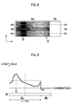
- the radiation source 20 is disposed to be deviated from the central axis O. Therefore, the distance from the radiation source 20 to the radiation detection medium 30 is not uniform along the outer circumference direction c. Accordingly, non-uniformity (radiation intensity unevenness) of the radiation intensity occurs on the radiation detection medium 30. That is, even if the radiation originating from the radiation source 20 is uniformly and omnidirectionally emitted and the thickness of the welded portion 12 is uniform (constant) along the outer circumference direction c, density irregularities occur along the outer circumference direction c (horizontal direction of Fig. 8 ) in the weld inspection fluoroscopic image 42.
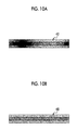
- density irregularities are removed through image processing from the weld inspection fluoroscopic image 42 in which there are density irregularities shown in Fig. 10A , and a weld inspection fluoroscopic image 46, in which there are no density irregularities shown in Fig. 10B , is output.
- density correction information for the weld inspection fluoroscopic image 42 with density irregularities is calculated, and density irregularity correction is performed in accordance with the density correction information.
- the weld inspection fluoroscopic image 46 without density irregularities is generated.
- a region which is indicated by a reference numeral 42b, is a region corresponding to a portion (detection-ineffective portion 30b) of the radiation detection medium 30 having an overlap.
- the region is not shown in Figs. 10A and 10B .
- the image processing device 50 of Fig. 11 includes: a scanner 51 (fluoroscopic image acquisition unit), a storage section 52, a display section 53, an operation section 54, and a control section 55 (density profile generation unit, density correction information calculation unit, and density correction unit).
- the display section 53 displays various kinds of information including the fluoroscopic images (the reference fluoroscopic image and the weld inspection fluoroscopic image) and the density profiles (the reference density profile and the weld inspection density profile).
- the display section 53 is constituted by a display device such as a liquid crystal display device.
- the operation section 54 receives various instruction inputs.
- the operation section 54 is constituted by an instruction input device such as a keyboard or a touch panel.
- the control section 55 is constituted by a microcomputer.
- the control section 55 performs various kinds of processing in accordance with a program which is stored in advance in the storage section 52.
- control section 55 has a function (density correction information calculation function) of calculating density correction information, as a second function, on the basis of two different density profiles.
- the density correction information is for correction that matches the relationships (density patterns) between the density values and the coordinates of one fluoroscopic image and another fluoroscopic image in the specific direction.
- control section 55 has a function (fluoroscopic image display control function) of displaying the fluoroscopic image on the display section 53, as a fourth function.
- the control section 55 generates the weld inspection density profile by performing curve approximation on the change in density values in the outer circumference direction c of the weld inspection fluoroscopic image 42.
- straight-line approximation may be performed.
- the curve approximation may be performed using a well-known method. Further, by calculating an average value of the density values for each pixel group with a predetermined number of pixels along the outer circumference direction c, the density profile may be temporarily generated.
- the cross-section of the pipe 10 is circular, and the radiation detection medium 30 is wound around the circumference. That is, when there are positioning errors dx and dy, the distance from the radiation source 20 to each position (coordinates) of the radiation detection medium 30 regularly changes along the outer circumference direction c. In accordance with the change, as density irregularities, the density values regularly increase and decrease along the outer circumference direction c. Therefore, the curve approximation is performed using regular change in density values along the outer circumferential direction c.
- control section 55 of the present example generates a density profile of a welded region 42d and a density profile of a non-welded region 42c in the weld inspection fluoroscopic image 42.
- the "welded region” is a region corresponding to the welded portion 12 of the pipes 10 in the weld inspection fluoroscopic image 42.
- the "non-welded region” is a region corresponding to the non-welded portion 14 of the pipes 10 in the weld inspection fluoroscopic image 42.
- the respective density profiles are generated along a plurality of lines (only three lines 44a, 44b, and 44c are shown in Fig. 8 ) in the outer circumference direction c.
- the control section 55 of the present example calculates a ratio of density values (a ratio of the density value of the weld inspection density profile to the density value of the reference density profile) at each set of the coordinates corresponding to each other in the outer circumference direction c on the basis of the reference density profile and the weld inspection density profile. Thereby, the control section 55 calculates a correction coefficient (an inverse of the ratio of the density values) for each set of the coordinates along the outer circumference direction c in the weld inspection fluoroscopic image.
- control section 55 generates the density correction information about the welded region 42d on the basis of the density profile of the welded region 42d, and generates the density correction information about the non-welded region 42c on the basis of the density profile of the non-welded region 42c.
- control section 55 of the present example corrects density irregularities in the welded region 42d on the basis of the density correction information about the welded region 42d, and corrects density irregularities in the non-welded region 42c on the basis of the density correction information about the non-welded region 42c.
- the control section 55 of the present example calculates coordinates (near-radiation-source coordinates 43 of Figs. 8 and 9 ), which indicate a position in the weld inspection fluoroscopic image 42, on the basis of the weld inspection density profile.
- the position corresponds to a position closest to the radiation source 20 on the radiation detection medium 30.
- the coordinates at which the density is highest is the near-radiation-source coordinates. That is, in the horizontal axis direction (outer circumference direction c) of the weld inspection density profile shown in Fig. 9 , the coordinates at which the density value is the maximum value is the near-radiation-source coordinates.
- the control section 55 generates the respective density profiles along the plurality of lines (only three lines 44a, 44b, and 44c are shown in Fig. 8 ) in the outer circumference direction c, calculates the coordinates (maximum value coordinates) with maximum value for each density profile, and estimates the near-radiation-source coordinates 43 on the basis of the plurality of maximum value coordinates.
- control section 55 records the estimated near-radiation-source coordinates in the storage section 52 in association with the weld inspection fluoroscopic image (at least one fluoroscopic image of the weld inspection fluoroscopic image in which density irregularities are corrected and the weld inspection fluoroscopic image in which density irregularities are not corrected).
- the control section 55 of the present example calculates an outer diameter (radius) of the pipe 10 on the basis of the weld inspection fluoroscopic image or the weld inspection density profile. Further, the control section 55 records attribute information including the outer diameter r in the storage section 52 in association with the weld inspection fluoroscopic image (at least one fluoroscopic image of the weld inspection fluoroscopic image in which density irregularities are corrected and the weld inspection fluoroscopic image in which density irregularities are not corrected).
- Fig. 12 is a flowchart illustrating a flow from the reference fluoroscopic image acquisition to the reference profile storage.
- the reference fluoroscopic image may be acquired from the storage section 52.
- the reference density profile is stored in the storage section 52 in association with the reference fluoroscopic image 40 (step S6).
- Fig. 13 is a flowchart illustrating a flow from the weld inspection fluoroscopic image acquisition to the density correction of the weld inspection fluoroscopic image.
- the weld inspection fluoroscopic image is acquired (step S12).
- the radiation source 20 is disposed inside the welded portion 12 of the inspection target pipe 10, and the flexible radiation detection medium 30 is wound around the outer circumference of the welded portion 12 of the inspection target pipe 10.
- the radiation which originates from the radiation source 20 during a constant time period and is transmitted through the welded portion 12 of the pipe 10, is detected through the radiation detection medium 30.
- the weld inspection fluoroscopic image is generated through the radiation detection medium 30.
- the weld inspection fluoroscopic image may be acquired from the storage section 52.
- the weld inspection density profile shown in Fig. 9 is generated (step S14).
- the weld inspection density profile indicates the relationship between the density values and the coordinates (density pattern) of the weld inspection fluoroscopic image in the direction c along the outer circumference of the welded portion 12 of the inspection target pipe 10.
- the reference fluoroscopic image and the weld inspection fluoroscopic image, in which density irregularities are corrected are displayed on the display section 53 (step S22).
- the control section 55 of the present example causes a screen (display screen) of the display section 53 to display both the weld inspection fluoroscopic image, in which density irregularities are corrected, and the reference fluoroscopic image.
- control section 55 of the present example causes the screen (display screen) of the display section 53 to display both the weld inspection fluoroscopic image, in which density irregularities are corrected, and the weld inspection fluoroscopic image, in which density irregularities are not corrected, in response to an instruction input from the operation section 54.
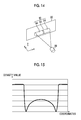
- Fig. 14 is a schematic diagram illustrating a situation of capture of a fluoroscopic image during maintenance inspection (hereinafter referred to as a "maintenance inspection fluoroscopic image").
- the radiation source 20 and the radiation detection medium 30 are disposed to face each other with the welded portion 12 of the inspection target pipe 10 interposed therebetween.
- the radiation emitted from the radiation source 20 is transmitted through the welded portion 12 of the pipe 10 and a non-welded portion 14 around the welded portion 12, and is detected by the radiation detection medium 30.
- the radiation detection medium 30 generates a maintenance inspection fluoroscopic image corresponding to a distribution of radiation intensity on the radiation detection medium 30.
- Errors (positioning errors) between the ideal position of the radiation source 20 and the real position of the radiation source 20 are roughly classified into an error in the x direction (the length direction of the pipe 10) of Fig. 14 , an error in the y direction (the direction of the distance from the radiation source 20 to the pipe 10) of Fig. 14 , and an error in the z direction (the direction intersecting with the pipe 10) of Fig. 14 .
- density irregularities occur in the fluoroscopic image which is generated through the radiation detection medium 30.
- Fig. 15 shows an example of a density profile (hereinafter referred to as a "maintenance inspection density profile").
- the density profile is generated by the control section 55 of the image processing device 50, on the basis of the maintenance inspection fluoroscopic image acquired from the radiation detection medium 30.
- the maintenance inspection density profile indicates a density pattern (a relationship between the density values and the z coordinates) in the direction z intersecting with the pipe 10.
- the scanner 51 acquires the maintenance inspection fluoroscopic image from the radiation detection medium 30.
- the storage section 52 stores various kinds of information including the maintenance inspection fluoroscopic image and the maintenance inspection density profile.
- the display section 53 displays various kinds of information including the maintenance inspection fluoroscopic image and the maintenance inspection density profile.
- the control section 55 executes various kinds of processing, in accordance with programs which are stored in the storage section 52 in advance.
- the control section 55 has a density profile generation function, a density correction information calculation function, a density irregularity correction function, a fluoroscopic image display control function, and the like.
- control section 55 During the maintenance inspection, the control section 55 generates the maintenance inspection density profile on the basis of the maintenance inspection fluoroscopic image.
- the maintenance inspection density profile indicates a relationship between the density values and the coordinates of the maintenance inspection fluoroscopic image in a specific direction. Further, during the maintenance inspection, the control section 55 calculates correction information (inspection density correction information) on the basis of the maintenance inspection density profile (first inspection density profile) at the previous maintenance inspection and the maintenance inspection density profile (second inspection density profile) at the current maintenance inspection.
- the correction information is for matching relationships between the density values and the coordinates of the previous maintenance inspection fluoroscopic image (first inspection fluoroscopic image) and the current maintenance inspection fluoroscopic image (second inspection fluoroscopic image) in the specific direction. Furthermore, during the maintenance inspection, the control section 55 performs the density irregularity correction, on the basis of the inspection density correction information. The correction is for matching relationships between the density values and the coordinates of the previous maintenance inspection fluoroscopic image and the current maintenance inspection fluoroscopic image in the specific direction.
- the density irregularities include density irregularities which appear along the horizontal direction (corresponding to the length direction of the pipe 10) of the maintenance inspection fluoroscopic image since the radiation source 20 is deviated from a target position (the center of the welded portion 12, for example, the contact point between the pipe 10 and the pipe 10) in the length direction (the x direction of Fig. 14 ) of the pipe 10. Further, the density irregularities include density irregularities which appear along the vertical direction (corresponding to the direction y intersecting with the pipe 10) of the maintenance inspection fluoroscopic image since the radiation source 20 is deviated from a target position in the direction (the y direction of Fig. 14 ) from the radiation source 20 toward the pipe 10. Furthermore, the density irregularities include density irregularities which appear along the vertical direction (corresponding to the z direction) of the maintenance inspection fluoroscopic image since the radiation source 20 is deviated from a target position in the z direction of Fig. 14 .
- the control section 55 of the present example generates the maintenance inspection density profile shown in Fig. 15 by performing curve approximation on the change in density values in the direction (the z direction of Fig. 14 ) intersecting with the pipe of the maintenance inspection fluoroscopic image.
- the control section 55 of the present example causes the screen (display screen) of the display section 53 to display both the fluoroscopic image (the second inspection fluoroscopic image obtained after the density correction), in which density irregularities are corrected, at the current maintenance inspection and the fluoroscopic image (the first inspection fluoroscopic image obtained after the correction), in which density irregularities are corrected, at the previous maintenance inspection.
- control section 55 of the present example causes the screen (display screen) of the display section 53 to display both the current maintenance inspection fluoroscopic image (the second inspection fluoroscopic image obtained after the density correction), in which density is corrected, and the current maintenance inspection fluoroscopic image (the second inspection fluoroscopic image obtained before the density correction), in which density is not corrected, in response to an instruction input from the operation section 54.
- the control section 55 of the present example enlarges or reduces the fluoroscopic image (the second inspection fluoroscopic image obtained after the density correction), in which density irregularities are corrected, at the current maintenance inspection and the fluoroscopic image (the first inspection fluoroscopic image obtained after the density correction), in which the density irregularities are corrected, at the previous maintenance inspection, on the basis of the diameter of the pipe calculated during the weld inspection, and causes the screen (display screen) of the display section 53 to display the fluoroscopic images.
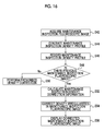
- the maintenance inspection fluoroscopic image is acquired (step S42).
- the radiation source 20 and the sheet-like radiation detection medium 30 are disposed to face each other with the welded portion 12 of the inspection target pipe 10 interposed therebetween. Radiation is emitted from the radiation source 20 during a constant time period, and the radiation transmitted through the welded portion 12 of the pipe 10 is detected through the radiation detection medium 30 which is disposed to face the radiation source 20. Thereby, the maintenance inspection fluoroscopic image is generated through the radiation detection medium 30.
- the dedicated scanner 51 reads the maintenance inspection fluoroscopic image from the radiation detection medium 30, thereby acquiring the maintenance inspection fluoroscopic image, and the image is stored in the storage section 52.
- the maintenance inspection density profile shown in Fig. 15 is generated (step S44).
- the maintenance inspection density profile indicates a density pattern (a relationship between the density values and the coordinates) of the maintenance inspection fluoroscopic image in the specific direction (the z direction in the present example).
- the maintenance inspection fluoroscopic image and the maintenance inspection density profile are associated with each other and are recorded in the storage section 52 (step S46).
- the control section 55 calculates the maintenance inspection density correction information on the basis of the previous maintenance inspection density profile (first inspection density profile) and the current maintenance inspection density profile (second inspection density profile) (step S52).
- the information is for matching density patterns (relationships between the density values and the coordinates) of the current maintenance inspection fluoroscopic image and the previous maintenance inspection fluoroscopic image in the specific direction (the z direction in the present example).
- step S54 the density correction of the current maintenance inspection fluoroscopic image is performed.
Landscapes
- Engineering & Computer Science (AREA)
- Physics & Mathematics (AREA)
- General Physics & Mathematics (AREA)
- Health & Medical Sciences (AREA)
- Computer Vision & Pattern Recognition (AREA)
- Theoretical Computer Science (AREA)
- Immunology (AREA)
- Pathology (AREA)
- Life Sciences & Earth Sciences (AREA)
- Chemical & Material Sciences (AREA)
- Analytical Chemistry (AREA)
- Biochemistry (AREA)
- General Health & Medical Sciences (AREA)
- Multimedia (AREA)
- Radiology & Medical Imaging (AREA)
- Quality & Reliability (AREA)
- Nuclear Medicine, Radiotherapy & Molecular Imaging (AREA)
- Electromagnetism (AREA)
- Analysing Materials By The Use Of Radiation (AREA)
- Geometry (AREA)
Abstract
Description
- The present invention relates to a fluoroscopic image density correction method, a non-destructive inspection method, and an image processing device capable of non-destructively inspecting for defects of welded portions of pipes in a case of welding a plurality of pipes. In particular, the present invention relates to a fluoroscopic image density correction method, a non-destructive inspection method, and an image processing device capable of obtaining the same inspection results without dependency on the skill level of an inspector for identification in images even if density irregularities occur in a fluoroscopic image.
- There is a known method of non-destructively inspecting for defects of welded portions of pipes in a case of welding a plurality of pipes. For example, non-destructive inspection is performed as follows. First, radiation, which originates from a radiation source and is transmitted through a welded portion of pipes, is detected by a sheet-like radiation detection medium. A fluoroscopic image, which is generated by the radiation detection medium, is read from the radiation detection medium by a dedicated scanner. The read fluoroscopic image is displayed on a display screen of a personal computer (hereinafter referred to as "PC"), and an inspector checks the image visually.
- In the disclosure of
JP2012-47569A - In the disclosure of
JP1987-277542A JP-S62-277542A - In the disclosure of
JP1986-274210A JP-S61-274210A - In the disclosure of
JP2005-037193A - In the disclosure of
JP2003-190125A - In a fluoroscopic image of a welded portion of pipes, not only contrasts in density caused by defects (such as bubbles and cracks) of the welded portion but also various density irregularities are exhibited. For example, distances from a radiation source are not uniform on a radiation detection medium, and thus density irregularities are caused. Further, since an amount of deviation (positioning error) from an ideal position of the radiation source is different for each inspection, density irregularities shown in the fluoroscopic image are different for each inspection. That is, there is a following problem. In the fluoroscopic image of the welded portion of the pipes, not only various density irregularities are exhibited, but also density irregularities different for each inspection are exhibited. Thereby, identification of defects of the welded portion of the pipes greatly depends on an individual identification skill of an inspector who performs visual inspection of the fluoroscopic image. Consequently, there are following problems. In order to prevent erroneous identification, a high-level identification skill is necessary for an inspector, and determination results may be different in accordance with a skill of an inspector.
- In the disclosure of
JP2012-47569A - In the disclosure of
JP1987-277542A JP-S62-277542A - In the disclosure of
JP1986-274210A JP-S61-274210A - In the disclosure of
JP2005-037193A - In the disclosure of
JP2003-190125A - The present invention has been made in consideration of such situations, and its object is to obtain the same inspection results without dependency on the skill level of an inspector for identification in images even if density irregularities occur in a fluoroscopic image of a welded portion of pipes when inspection or measurement is performed using the fluoroscopic image of the welded portion of the pipes.
- In order to achieve the object, according to an aspect of the present invention, there is provided a fluoroscopic image density correction method including: acquiring a reference fluoroscopic image generated from a flexible radiation detection medium, which is disposed on an outer circumference of a reference pipe having a reference welded portion, when a radiation source is disposed on a central axis of the reference pipe and radiation originating from the radiation source is detected by the radiation detection medium; generating a reference density profile, which indicates a relationship between density values and coordinates on the reference fluoroscopic image in a direction along the outer circumference of the reference pipe, on the basis of the reference fluoroscopic image; acquiring a weld inspection fluoroscopic image generated from a flexible radiation detection medium, which is disposed on an outer circumference of an inspection target pipe, when a radiation source is disposed inside an inspection target pipe having an inspection target welded portion and radiation originating from the radiation source is detected by the radiation detection medium; generating a weld inspection density profile, which indicates a relationship between density values and coordinates on the weld inspection fluoroscopic image in a direction along the outer circumference of the inspection target pipe, on the basis of the weld inspection fluoroscopic image; calculating weld inspection density correction information for correcting density irregularities in the weld inspection fluoroscopic image in the direction along the outer circumference of the inspection target pipe, on the basis of the reference density profile and the weld inspection density profile; and correcting the density irregularities in the weld inspection fluoroscopic image in the direction along the outer circumference of the inspection target pipe, on the basis of the weld inspection density correction information. With such a configuration, the reference density profile, which indicates a relationship between density values and coordinates in the direction along the outer circumference of the pipe, is acquired on the basis of the reference fluoroscopic image which is obtained by performing radiographic imaging on the pipe having the reference welded portion, the weld inspection density profile, which indicates a relationship between density values and coordinates in the direction along the outer circumference of the pipe, is acquired on the basis of the weld inspection fluoroscopic image which is obtained by performing radiographic imaging on the pipe having the inspection target welded portion, and density irregularities in the direction along the outer circumference of the inspection target pipe are removed from the weld inspection fluoroscopic image through correction on the basis of the reference density profile and the weld inspection density profile. Therefore, it is possible to obtain the same inspection results without dependency on the skill level of an inspector for identification in images even if density irregularities occur in the weld inspection fluoroscopic image.
- According to an aspect of the present invention, in the generating of the weld inspection density profile, a density profile of a welded region and a density profile of a non-welded region are generated, in which the welded region corresponds to the welded portion of the inspection target pipe in the weld inspection fluoroscopic image, and the non-welded region corresponds to the non-welded portion of the inspection target pipe in the weld inspection fluoroscopic image, in the calculating of the weld inspection density correction information, density correction information about the welded region of the weld inspection fluoroscopic image is calculated on the basis of the density profile of the welded region, and density correction information about the non-welded region of the weld inspection fluoroscopic image is calculated on the basis of the density profile of the non-welded region, and in the correcting of the weld inspection density, density irregularities of the welded region are corrected on the basis of the density correction information about the welded region, and density irregularities of the non-welded region are corrected on the basis of the density correction information about the non-welded region. With such a configuration, even when density patterns of the welded portion and the non-welded portion are different, density irregularities in the outer circumference direction are reliably removed from the weld inspection fluoroscopic image.
- According to an aspect of the present invention, in the generating of the weld inspection density profile, the weld inspection density profile is generated by performing curve approximation on change in the density value of the weld inspection fluoroscopic image in the direction along the outer circumference. With such a configuration, even when various defects occur in the welded portion, it is possible to reliably remove only density irregularities, and it is also possible to reliably leave contrast of the defects.
- According to an aspect of the present invention, the fluoroscopic image density correction method further includes estimating near-radiation-source coordinates, which indicate a position on the weld inspection fluoroscopic image corresponding to a position closest to the radiation source on the radiation detection medium, on the basis of the weld inspection density profile, in which the near-radiation-source coordinates are recorded in association with at least either one of the weld inspection fluoroscopic image in which the density irregularities are corrected or the weld inspection fluoroscopic image in which the density irregularities are not corrected. With such a configuration, even after density irregularities are removed from the weld inspection fluoroscopic image, it is possible to check a position at which the density value is at the minimum due to positional deviation of the radiation source.
- According to an aspect of the present invention, a diameter of the inspection target pipe is calculated on the basis of the weld inspection fluoroscopic image or the weld inspection density profile, and the diameter of the inspection target pipe is recorded in association with either one of the weld inspection fluoroscopic image in which the density irregularities are corrected or the weld inspection fluoroscopic image in which the density irregularities are not corrected. With such a configuration, when there is an error in the diameter of the inspection target pipe, even though the diameter of the pipe is not actually measured, it is possible to detect an actual diameter of the pipe.
- According to an aspect of the present invention, the weld inspection fluoroscopic image, in which density irregularities are corrected, is displayed on a display screen, together with the reference fluoroscopic image. Thereby, it is possible to easily identify whether or not there are defects in the welded portion.
- According to an aspect of the present invention, the weld inspection fluoroscopic image, in which density irregularities are corrected, is displayed on the display screen, together with the weld inspection fluoroscopic image in which density irregularities are not corrected. Thereby, it is possible to easily detect defects by visually checking the weld inspection fluoroscopic image obtained after the density irregularity correction, and it is also possible to reliably check whether or not there are defects in the weld inspection fluoroscopic image obtained before the density irregularity correction.
- Further, according to an aspect of the present invention, there is provided a fluoroscopic image density correction method including: acquiring a first inspection fluoroscopic image generated from a radiation detection medium, which is disposed to face a radiation source with a welded portion of an inspection target pipe interposed therebetween, at a first inspection; generating a first inspection density profile, which indicates a relationship between a density value and coordinates of the first inspection fluoroscopic image, on the basis of the first inspection fluoroscopic image; acquiring a second inspection fluoroscopic image generated from a radiation detection medium, which is disposed to face a radiation source with the welded portion of the inspection target pipe interposed therebetween, at a second inspection; generating a second inspection density profile, which indicates a relationship between a density value and coordinates of the second inspection fluoroscopic image, on the basis of the second inspection fluoroscopic image; calculating inspection density correction information for matching relationships between the density values and the coordinates of the first inspection fluoroscopic image and the second inspection fluoroscopic image, on the basis of the first inspection density profile and the second inspection density profile; and performing density correction for matching relationships between the density values and the coordinates of the first inspection fluoroscopic image and the second inspection fluoroscopic image, on the basis of the inspection density correction information. With such a configuration, the first inspection density profile, which indicates a relationship between the density values and the coordinates, is acquired on the basis of the first inspection fluoroscopic image which is obtained by performing the first inspection (previous inspection), the second inspection density profile, which indicates a relationship between the density values and the coordinates, is acquired on the basis of the second inspection fluoroscopic image which is obtained by performing the second inspection (current inspection), and density irregularities of the inspection target pipe are removed from the second inspection fluoroscopic image (current inspection fluoroscopic image) on the basis of the first inspection density profile (the density profile of the previous inspection) and the second inspection density profile (the density profile of the current inspection). Therefore, it is possible to reliably detect occurrence of defects without dependency on the skill level of an inspector for identification in images even if density irregularities occur in the inspection fluoroscopic image.
- According to an aspect of the present invention, in the generating of the first inspection density profile, the first inspection density profile is generated by performing curve approximation on change in the density value of the first inspection fluoroscopic image in a direction intersecting with the pipe, and in the generating of the second inspection density profile, the second inspection density profile is generated by performing curve approximation on change in the density value of the second inspection fluoroscopic image in a direction intersecting with the pipe. With such a configuration, even when various defects occur in the welded portion, it is possible to reliably remove only density irregularities, and it is also possible to reliably leave contrast of the defects.
- According to an aspect of the present invention, the second inspection fluoroscopic image, in which density is corrected by the fluoroscopic image density correction method, is displayed on a display screen, together with the first inspection fluoroscopic image in which density is corrected. Thereby, it is possible to reliably identify defects which have newly occurred in the welded portion.
- According to an aspect of the present invention, the first inspection fluoroscopic image and the second inspection fluoroscopic image, in which density is corrected by the fluoroscopic image density correction method, are displayed on the display screen in a reduced manner on the basis of the diameter of the calculated inspection target pipe. With such a configuration, when there is an error in the diameter of the inspection target pipe, even though the diameter of the pipe is not actually measured, it is possible to increase or decrease the size of the inspection fluoroscopic image to an appropriate size.
- According to an aspect of the present invention, the second inspection fluoroscopic image, in which density is corrected, is displayed on the display screen, together with the second inspection fluoroscopic image in which density is not corrected.
- Further, according to an aspect of the present invention, there is provided an image processing device including: a fluoroscopic image acquisition unit that acquires a reference fluoroscopic image generated from a flexible radiation detection medium, which is disposed on an outer circumference of a reference pipe having a reference welded portion, when a radiation source is disposed on a central axis of the reference pipe and radiation originating from the radiation source is detected by the radiation detection medium, and a weld inspection fluoroscopic image generated from a flexible radiation detection medium, which is disposed on an outer circumference of an inspection target pipe, when a radiation source is disposed inside an inspection target pipe having an inspection target welded portion and radiation originating from the radiation source is detected by the radiation detection medium at the time of weld inspection; a density profile generation unit that generates a reference density profile, which indicates a relationship between a density value and coordinates on the reference fluoroscopic image in a direction along the outer circumference of the reference pipe, on the basis of the reference fluoroscopic image, and generating a weld inspection density profile, which indicates a relationship between a density value and coordinates on the weld inspection fluoroscopic image in a direction along the outer circumference of the inspection target pipe, on the basis of the weld inspection fluoroscopic image; a density correction information calculation unit that calculates weld inspection density correction information for correcting density irregularities in the weld inspection fluoroscopic image in the direction along the outer circumference of the inspection target pipe, on the basis of the reference density profile and the weld inspection density profile; and a density correction unit that corrects the density irregularities in the weld inspection fluoroscopic image in the direction along the outer circumference of the inspection target pipe, on the basis of the weld inspection density correction information.
- Furthermore, according to an aspect of the present invention, there is provided an image processing device including: a fluoroscopic image acquisition unit that acquires an inspection fluoroscopic image generated from a radiation detection medium which is disposed to face a radiation source with a welded portion of an inspection target pipe interposed therebetween; a density profile generation unit that generates an inspection density profile, which indicates a relationship between a density value and coordinates of the inspection fluoroscopic image, on the basis of the inspection fluoroscopic image; a density correction information calculation unit that calculates inspection density correction information for matching relationships between the density values and the coordinates of the inspection fluoroscopic image obtained at a previous inspection and the inspection fluoroscopic image obtained at a current inspection, on the basis of a first inspection density profile generated from the inspection fluoroscopic image obtained at the previous inspection and a second inspection density profile generated from the inspection fluoroscopic image obtained at the current inspection; and a density correction unit that performs density correction for matching relationships between the density values and the coordinates of the inspection fluoroscopic image obtained at the previous inspection and the inspection fluoroscopic image obtained at the current inspection, on the basis of the inspection density correction information.
- According to the aspects of the present invention, it is possible to obtain the same inspection results without dependency on the skill level of an inspector for identification in images even if density irregularities occur in the fluoroscopic image of the welded portion of the pipes when inspection or measurement is performed using the fluoroscopic image of the welded portion of the pipes.
-
-
Figs. 1A, 1B, and 1C are schematic diagrams illustrating situations of capture of fluoroscopic images during weld inspection. -
Fig. 2 is a perspective view illustrating a positioning error of a radiation source. -
Fig. 3 is a diagram illustrating a cross-section taken along the line 3-3 ofFig. 2 . -
Fig. 4 is a cross-sectional view illustrating a state where the radiation source is disposed on the central axis of a welded portion of pipes. -
Fig. 5 is a diagram illustrating an example of a reference fluoroscopic image which is obtained through radiographic imaging in the state ofFig. 4 . -
Fig. 6 is a diagram illustrating a density profile of the reference fluoroscopic image ofFig. 5 . -
Fig. 7 is a cross-sectional view illustrating a state where the radiation source is disposed to be deviated from the central axis of the welded portion of the pipes. -
Fig. 8 is a diagram illustrating an example of a weld inspection fluoroscopic image which is obtained through radiographic imaging in the state ofFig. 7 . -
Fig. 9 is a diagram illustrating a density profile of the weld inspection fluoroscopic image of 85. -
Figs. 10A and 10B are diagrams illustrating an example of density irregularity correction, whereFig. 10A is a weld inspection fluoroscopic image obtained before the density irregularity correction andFig. 10B is a weld inspection fluoroscopic image obtained after the density irregularity correction. -
Fig. 11 is a diagram illustrating a configuration example of an image processing device. -
Fig. 12 is a flowchart illustrating a flow to reference profile generation. -
Fig. 13 is a flowchart illustrating a flow to density correction of the weld inspection fluoroscopic image. -
Fig. 14 is a schematic diagram illustrating a situation of capture of a fluoroscopic image during maintenance inspection. -
Fig. 15 is an example of a density profile of a fluoroscopic image during the maintenance inspection. -
Fig. 16 is a flowchart illustrating a flow of fluoroscopic image correction processing during the maintenance inspection. - Hereinafter, according to the accompanying drawings, embodiments of the present invention will be described.
- First, density correction and display of a fluoroscopic image during weld inspection (inspection at the time of welding the pipe) will be described.
-
Figs. 1A, 1B, and 1C are schematic diagrams illustrating situations of capture of fluoroscopic images during weld inspection (hereinafter referred to as "weld inspection fluoroscopic images").Fig. 1A showspipes 10 which are not welded.Fig. 1B showspipes 10 which are welded.Fig. 1C shows apipe 10 in which aradiation source 20 emitting radiation and aradiation detection medium 30 detecting radiation are disposed. - In
Figs. 1A to 1C , for convenience of description, forms of thepipes 10 and weld forms of thepipes 10 are simplified. In practice, there are various forms of thepipes 10 and various weld forms of thepipes 10. Thereference numeral 12 indicates a welded portion of thepipes 10. In the present description, the "welded portion" means a welded part of thepipes 10, and includes a weld material. Theradiation source 20 is ideally disposed on a central axis O of thepipe 10 as shown inFig. 1C . Theradiation detection medium 30 is flexible, and is wound around an outer circumference of thepipe 10 including the weldedportion 12, as shown inFig. 1C . As theradiation detection medium 30, in the present example, an imaging plate (stimulable phosphor film) is used. The radiation originating from theradiation source 20 is transmitted through the weldedportion 12 of thepipe 10 and anon-welded portion 14 around the weldedportion 12, and is detected by theradiation detection medium 30. Theradiation detection medium 30 generates a weld inspection fluoroscopic image having a density pattern corresponding to a distribution of radiation intensity on theradiation detection medium 30. - Practically, in most cases, due to various situations of the field site in which the
pipes 10 are installed, theradiation source 20 may be disposed at a position deviated from the central axis O of thepipe 10, as shown in the perspective view ofFig. 2 and the cross-sectional view ofFig. 3 which shows a cross-section taken along the line 3-3 ofFig. 2 . - Errors (positioning errors) between an ideal position of the
radiation source 20 and a real position of theradiation source 20 are roughly classified into an error dx in a direction (length direction x) along the central axis O ofFig. 2 and errors dy and dz in the two directions (horizontal direction y, vertical direction z) which are orthogonal in the cross-section of thepipe 10 ofFig. 3 . When there are such errors dx, dy, and dz, the intensity of the radiation on theradiation detection medium 30 depends on a distance from theradiation source 20. Hence, density irregularities occur in a fluoroscopic image which is generated through theradiation detection medium 30. - As shown in
Fig. 4 , when theradiation source 20 is disposed at the ideal position on the central axis O of thepipe 10, for example, a fluoroscopic image 40 (hereinafter referred to as a "reference fluoroscopic image") shown inFig. 5 is acquired. The density profile (hereinafter referred to as a "reference density profile") of a referencefluoroscopic image 40 ofFig. 5 is shown inFig. 6 . The reference density profile indicates a density pattern (a relationship between the density values and the coordinates in an outer circumference direction c) of the referencefluoroscopic image 40 in the direction (outer circumference direction c) along the outer circumference of thepipe 10. InFig. 4 , for convenience of description, it is assumed that radiation is uniformly and omnidirectionally emitted from theradiation source 20, a thickness of the weldedportion 12 of thepipe 10 is uniform along the outer circumference direction c, and there are no defects in the weldedportion 12. - In
Fig. 4 , theradiation source 20 is disposed at the ideal position on the central axis O. Therefore, there are no positioning errors dx, dy, and dz of theradiation source 20 as shown inFigs. 2 and 3 (dx=dy=dz=0). That is, the distance from theradiation source 20 to theradiation detection medium 30 is uniformized along the outer circumference direction c. Accordingly, non-uniformity (radiation intensity unevenness) of the radiation intensity along the outer circumference direction c does not occur on theradiation detection medium 30. - In the reference
fluoroscopic image 40 shown inFig. 5 , in aregion 40a which corresponds to a portion (detection-effective portion 30a) of theradiation detection medium 30 having no overlap, non-uniformity (density irregularities) in density occurs in the outer circumference direction c. Here, if the thickness of the weldedportion 12 is not uniform, change in density corresponding to a degree of non-uniformity occurs in the image. In the referencefluoroscopic image 40 shown inFig. 5 , a region, which is indicated by areference numeral 40b, is a region corresponding to a portion (detection-ineffective portion 30b) of theradiation detection medium 30 having an overlap. - A weld inspection
fluoroscopic image 42, which is obtained when theradiation source 20 is disposed to be deviated from the central axis O as shown inFig. 7 , is shown inFig. 8 . Further, the density profile (hereinafter referred to as a "weld inspection density profile") of the weld inspectionfluoroscopic image 42 ofFig. 8 is shown inFig. 9 . In addition, for convenience of description, it is assumed that there is no positioning error dx in a length direction x (dx=0). Furthermore, there are no defects in the weldedportion 12. - In
Fig. 7 , theradiation source 20 is disposed to be deviated from the central axis O. Therefore, the distance from theradiation source 20 to theradiation detection medium 30 is not uniform along the outer circumference direction c. Accordingly, non-uniformity (radiation intensity unevenness) of the radiation intensity occurs on theradiation detection medium 30. That is, even if the radiation originating from theradiation source 20 is uniformly and omnidirectionally emitted and the thickness of the weldedportion 12 is uniform (constant) along the outer circumference direction c, density irregularities occur along the outer circumference direction c (horizontal direction ofFig. 8 ) in the weld inspectionfluoroscopic image 42. - When defects of the welded
portion 12 are detected by visually checking the weld inspectionfluoroscopic image 42 shown inFig. 8 , density irregularities along the outer circumference direction c of the weldedportion 12 occur. Therefore, even when there are defects in the weldedportion 12, it is difficult to detect the defects. - Accordingly, in the embodiment of the present invention, density irregularities are removed through image processing from the weld inspection
fluoroscopic image 42 in which there are density irregularities shown inFig. 10A , and a weld inspectionfluoroscopic image 46, in which there are no density irregularities shown inFig. 10B , is output. Specifically, on the basis of the reference density profile shown inFig. 6 and the weld inspection density profile shown inFig. 9 , density correction information for the weld inspectionfluoroscopic image 42 with density irregularities is calculated, and density irregularity correction is performed in accordance with the density correction information. Thereby, the weld inspectionfluoroscopic image 46 without density irregularities is generated. - In the weld inspection
fluoroscopic image 42 shown inFig. 8 , a region, which is indicated by areference numeral 42b, is a region corresponding to a portion (detection-ineffective portion 30b) of theradiation detection medium 30 having an overlap. Thus, the region is not shown inFigs. 10A and 10B . -
Fig. 11 is a block diagram illustrating a configuration example of animage processing device 50 used in a fluoroscopic image density correction method according to the embodiment of the present invention. - The
image processing device 50 ofFig. 11 includes: a scanner 51 (fluoroscopic image acquisition unit), astorage section 52, adisplay section 53, anoperation section 54, and a control section 55 (density profile generation unit, density correction information calculation unit, and density correction unit). - The
scanner 51 acquires fluoroscopic images (a reference fluoroscopic image and a weld inspection fluoroscopic image) from theradiation detection medium 30. - The
storage section 52 stores various kinds of information including the fluoroscopic images (the reference fluoroscopic image and the weld inspection fluoroscopic image) and the density profiles (the reference density profile and the weld inspection density profile). Thestorage section 52 is constituted by a storage device such as a memory or a disk. - The
display section 53 displays various kinds of information including the fluoroscopic images (the reference fluoroscopic image and the weld inspection fluoroscopic image) and the density profiles (the reference density profile and the weld inspection density profile). Thedisplay section 53 is constituted by a display device such as a liquid crystal display device. - The
operation section 54 receives various instruction inputs. Theoperation section 54 is constituted by an instruction input device such as a keyboard or a touch panel. - The
control section 55 is constituted by a microcomputer. Thecontrol section 55 performs various kinds of processing in accordance with a program which is stored in advance in thestorage section 52. - The
control section 55 has a function (density profile generation function) of generating the density profile (the reference density profile, the weld inspection density profile, and the like), as a first function. The density profile indicates a relationship between the density values and the coordinates of the fluoroscopic images (the reference fluoroscopic image, the weld inspection fluoroscopic image, and the like) in a specific direction. - During the weld inspection, the
control section 55 generates the reference density profile on the basis of the reference fluoroscopic image which is generated by theradiation detection medium 30 in a state where theradiation source 20 is disposed on the central axis of thepipe 10. The reference density profile indicates at least a relationship between the density values and the coordinates on the reference fluoroscopic image in the direction c along the outer circumference of thepipe 10. Further, thecontrol section 55 generates the weld inspection density profile on the basis of the weld inspection fluoroscopic image which is generated by theradiation detection medium 30 in a state where theradiation source 20 is disposed at a position deviated from the central axis of thepipe 10. The weld inspection density profile indicates at least a relationship between the density values and the coordinates on the weld inspection fluoroscopic image in the direction c along the outer circumference of theinspection target pipe 10. - Further, the
control section 55 has a function (density correction information calculation function) of calculating density correction information, as a second function, on the basis of two different density profiles. The density correction information is for correction that matches the relationships (density patterns) between the density values and the coordinates of one fluoroscopic image and another fluoroscopic image in the specific direction. - During the weld inspection, the
control section 55 calculates weld inspection density correction information, on the basis of the reference density profile and the weld inspection density profile. The information is for correcting the density irregularities in the weld inspection fluoroscopic image in the direction c along the outer circumference of theinspection target pipe 10. A specific example of the calculation will be described later. - Furthermore, the
control section 55 has a function (density irregularity correction function) of correcting density irregularities in the fluoroscopic image, as a third function, on the basis of the density correction information. Here, correction of density irregularities means removal of density irregularities or reduction in density irregularities. - During the weld inspection, the
control section 55 corrects the density irregularities in the weld inspection fluoroscopic image in the direction c along the outer circumference of theinspection target pipe 10, on the basis of the weld inspection density correction information. - In addition, the
control section 55 has a function (fluoroscopic image display control function) of displaying the fluoroscopic image on thedisplay section 53, as a fourth function. - The density profile indicates a correlation (density pattern) between the density values and the coordinates of the fluoroscopic image in the specific direction.
- As the density irregularities shown in the weld inspection fluoroscopic image, as described with reference to
Figs. 2 and 3 , there are density irregularities caused by the positioning errors dx, dy, and dz of theradiation source 20. In the weld inspectionfluoroscopic image 42 shown inFig. 8 , particularly, due to errors dy and dz along the cross-section of thepipe 10 shown inFig. 3 , the density irregularities shown along the outer circumference direction c make it difficult to visual identification as to whether or not there are defects in the weldedportion 12. Therefore, thecontrol section 55 generates the weld inspection density profile by performing curve approximation on the change in density values in the outer circumference direction c of the weld inspectionfluoroscopic image 42. However, if it is determined that straight-line approximation is better than curve approximation, straight-line approximation may be performed. The curve approximation may be performed using a well-known method. Further, by calculating an average value of the density values for each pixel group with a predetermined number of pixels along the outer circumference direction c, the density profile may be temporarily generated. Furthermore, the cross-section of thepipe 10 is circular, and theradiation detection medium 30 is wound around the circumference. That is, when there are positioning errors dx and dy, the distance from theradiation source 20 to each position (coordinates) of theradiation detection medium 30 regularly changes along the outer circumference direction c. In accordance with the change, as density irregularities, the density values regularly increase and decrease along the outer circumference direction c. Therefore, the curve approximation is performed using regular change in density values along the outer circumferential direction c. - In the weld inspection fluoroscopic image, when there is a defect in the welded
portion 12, a contrast is caused by the defect. However, by performing curve approximation, it is possible to obtain the weld inspection density profile which does not include the contrast caused by the defect. That is, thecontrol section 55 generates the weld inspection density profile which does not include the contrast caused by the defect and appropriately indicates density irregularities. - Further, the
control section 55 of the present example generates a density profile of a weldedregion 42d and a density profile of anon-welded region 42c in the weld inspectionfluoroscopic image 42. Here, the "welded region" is a region corresponding to the weldedportion 12 of thepipes 10 in the weld inspectionfluoroscopic image 42. Further, the "non-welded region" is a region corresponding to thenon-welded portion 14 of thepipes 10 in the weld inspectionfluoroscopic image 42. For example, the respective density profiles are generated along a plurality of lines (only threelines Fig. 8 ) in the outer circumference direction c. - Likewise, the
control section 55 of the present example generates the density profile of the welded region and the density profile of the non-welded region in the referencefluoroscopic image 40 through curve approximation or straight-line approximation. - The
control section 55 of the present example calculates a ratio of density values (a ratio of the density value of the weld inspection density profile to the density value of the reference density profile) at each set of the coordinates corresponding to each other in the outer circumference direction c on the basis of the reference density profile and the weld inspection density profile. Thereby, thecontrol section 55 calculates a correction coefficient (an inverse of the ratio of the density values) for each set of the coordinates along the outer circumference direction c in the weld inspection fluoroscopic image. - Further, the
control section 55 generates the density correction information about the weldedregion 42d on the basis of the density profile of the weldedregion 42d, and generates the density correction information about thenon-welded region 42c on the basis of the density profile of thenon-welded region 42c. - The
control section 55 of the present example performs the density correction by multiplying the correction coefficient for each set of the coordinates along the outer circumference direction c by the density value of each pixel of the weld inspection fluoroscopic image. - Furthermore, the
control section 55 of the present example corrects density irregularities in the weldedregion 42d on the basis of the density correction information about the weldedregion 42d, and corrects density irregularities in thenon-welded region 42c on the basis of the density correction information about thenon-welded region 42c. - The contrasts caused by defects such as scratches and bubbles in the fluoroscopic image are easily recognizable in the fluoroscopic image due to performing the density irregularity correction since change caused by the density irregularities along the specific direction (outer circumference direction c) is localized compared with density irregularities shown in the fluoroscopic image.
- The
control section 55 of the present example calculates coordinates (near-radiation-source coordinates 43 ofFigs. 8 and 9 ), which indicate a position in the weld inspectionfluoroscopic image 42, on the basis of the weld inspection density profile. The position corresponds to a position closest to theradiation source 20 on theradiation detection medium 30. - In the horizontal axis direction (outer circumference direction c) of the weld inspection
fluoroscopic image 42 shown inFig. 8 , the coordinates at which the density is highest is the near-radiation-source coordinates. That is, in the horizontal axis direction (outer circumference direction c) of the weld inspection density profile shown inFig. 9 , the coordinates at which the density value is the maximum value is the near-radiation-source coordinates. As shown inFig. 8 , thecontrol section 55 generates the respective density profiles along the plurality of lines (only threelines Fig. 8 ) in the outer circumference direction c, calculates the coordinates (maximum value coordinates) with maximum value for each density profile, and estimates the near-radiation-source coordinates 43 on the basis of the plurality of maximum value coordinates. - Further, the
control section 55 records the estimated near-radiation-source coordinates in thestorage section 52 in association with the weld inspection fluoroscopic image (at least one fluoroscopic image of the weld inspection fluoroscopic image in which density irregularities are corrected and the weld inspection fluoroscopic image in which density irregularities are not corrected). - The
control section 55 of the present example calculates an outer diameter (radius) of thepipe 10 on the basis of the weld inspection fluoroscopic image or the weld inspection density profile. Further, thecontrol section 55 records attribute information including the outer diameter r in thestorage section 52 in association with the weld inspection fluoroscopic image (at least one fluoroscopic image of the weld inspection fluoroscopic image in which density irregularities are corrected and the weld inspection fluoroscopic image in which density irregularities are not corrected). - When the outer diameter (radius) of the
pipe 10 is set as r, a length L of the portion (detection-effective portion 30a) of theradiation detection medium 30 having no overlap corresponds to the outer circumference of thepipe 10 of 2π (L=2πr). Accordingly, thecontrol section 55 detects coordinates of an edge 45 (a point at which the density value is suddenly lowered) of the density from the weld inspection density profile, calculates the length L of the detection-effective portion 30a of theradiation detection medium 30 corresponding to the coordinates of the edge 45 on the basis of the coordinates of the edge 45 and a resolution of the weld inspection fluoroscopic image, and calculates the outer diameter r (=L/2π) of thepipe 10 on the basis of the length L. - Next, a flow of an example of density correction processing of the fluoroscopic image during the weld inspection will be described.
-
Fig. 12 is a flowchart illustrating a flow from the reference fluoroscopic image acquisition to the reference profile storage. - First, the reference fluoroscopic image is acquired (step S2). For example, as shown in
Fig. 1C , theradiation source 20 is disposed on the central axis O of thereference pipe 10, and the flexibleradiation detection medium 30 is wound around the outer circumference of the weldedportion 12 of thereference pipe 10. The radiation, which originates from theradiation source 20 during a constant time period and is transmitted through the weldedportion 12 of thepipe 10, is detected through theradiation detection medium 30. The reference fluoroscopic image is generated through theradiation detection medium 30. Thus, theradiation detection medium 30 is removed from the weldedportion 12 of thepipe 10, and adedicated scanner 51 reads the reference fluoroscopic image from theradiation detection medium 30. Thereby, the referencefluoroscopic image 40 shown inFig. 5 is acquired, and is stored in thestorage section 52. - It should be noted that, when a reference fluoroscopic image is stored in the
storage section 52 in advance, the reference fluoroscopic image may be acquired from thestorage section 52. - Next, on the basis of the reference fluoroscopic image, the reference density profile shown in
Fig. 6 is generated (step S4). The reference density profile indicates the relationship between the density values and the coordinates (density pattern) of the reference fluoroscopic image in the direction c along the outer circumference of the weldedportion 12 of thereference pipe 10. - Next, the reference density profile is stored in the
storage section 52 in association with the reference fluoroscopic image 40 (step S6). -
Fig. 13 is a flowchart illustrating a flow from the weld inspection fluoroscopic image acquisition to the density correction of the weld inspection fluoroscopic image. - After a welding operation between the
pipe 10 and thepipe 10 at the weld field site is performed, the weld inspection fluoroscopic image is acquired (step S12). For example, as shown inFig. 7 , theradiation source 20 is disposed inside the weldedportion 12 of theinspection target pipe 10, and the flexibleradiation detection medium 30 is wound around the outer circumference of the weldedportion 12 of theinspection target pipe 10. The radiation, which originates from theradiation source 20 during a constant time period and is transmitted through the weldedportion 12 of thepipe 10, is detected through theradiation detection medium 30. The weld inspection fluoroscopic image is generated through theradiation detection medium 30. Then, theradiation detection medium 30 is removed from the weldedportion 12 of thepipe 10, and adedicated scanner 51 reads the weld inspection fluoroscopic image from theradiation detection medium 30. Thereby, the weld inspectionfluoroscopic image 42 shown inFig. 8 is acquired. - It should be noted that, when a weld inspection fluoroscopic image is stored in the
storage section 52 in advance, the weld inspection fluoroscopic image may be acquired from thestorage section 52. - Next, on the basis of the weld inspection fluoroscopic image, the weld inspection density profile shown in
Fig. 9 is generated (step S14). The weld inspection density profile indicates the relationship between the density values and the coordinates (density pattern) of the weld inspection fluoroscopic image in the direction c along the outer circumference of the weldedportion 12 of theinspection target pipe 10. - Next, on the basis of the reference density profile and the weld inspection density profile, weld inspection density correction information is calculated (step S16). The information is for correcting density irregularities in the weld inspection fluoroscopic image in the direction c along the outer circumference of the
inspection target pipe 10. - Next, on the basis of the weld inspection density profile, attribute information is calculated (step S18). In the present example, the outer diameter r (radius) of the
inspection target pipe 10 and the near-radiation-source coordinates 43 are calculated. - Next, on the basis of the weld inspection density correction information, the density irregularities in the weld inspection fluoroscopic image in the direction c along the outer circumference of the welded
portion 12 of thepipe 10 are corrected (step S20). - Next, the reference fluoroscopic image and the weld inspection fluoroscopic image, in which density irregularities are corrected, are displayed on the display section 53 (step S22).
- The
control section 55 of the present example causes a screen (display screen) of thedisplay section 53 to display both the weld inspection fluoroscopic image, in which density irregularities are corrected, and the reference fluoroscopic image. - Further, the
control section 55 of the present example causes the screen (display screen) of thedisplay section 53 to display both the weld inspection fluoroscopic image, in which density irregularities are corrected, and the weld inspection fluoroscopic image, in which density irregularities are not corrected, in response to an instruction input from theoperation section 54. - Next, density correction and display of a fluoroscopic image during maintenance inspection (inspection at the time of pipe maintenance) will be described.
-
Fig. 14 is a schematic diagram illustrating a situation of capture of a fluoroscopic image during maintenance inspection (hereinafter referred to as a "maintenance inspection fluoroscopic image"). As shown inFig. 14 , during the maintenance inspection, theradiation source 20 and theradiation detection medium 30 are disposed to face each other with the weldedportion 12 of theinspection target pipe 10 interposed therebetween. The radiation emitted from theradiation source 20 is transmitted through the weldedportion 12 of thepipe 10 and anon-welded portion 14 around the weldedportion 12, and is detected by theradiation detection medium 30. Theradiation detection medium 30 generates a maintenance inspection fluoroscopic image corresponding to a distribution of radiation intensity on theradiation detection medium 30. - Errors (positioning errors) between the ideal position of the
radiation source 20 and the real position of theradiation source 20 are roughly classified into an error in the x direction (the length direction of the pipe 10) ofFig. 14 , an error in the y direction (the direction of the distance from theradiation source 20 to the pipe 10) ofFig. 14 , and an error in the z direction (the direction intersecting with the pipe 10) ofFig. 14 . When such an error occurs, density irregularities occur in the fluoroscopic image which is generated through theradiation detection medium 30. -
Fig. 15 shows an example of a density profile (hereinafter referred to as a "maintenance inspection density profile"). The density profile is generated by thecontrol section 55 of theimage processing device 50, on the basis of the maintenance inspection fluoroscopic image acquired from theradiation detection medium 30. The maintenance inspection density profile indicates a density pattern (a relationship between the density values and the z coordinates) in the direction z intersecting with thepipe 10. - By using the
image processing device 50 shown inFig. 11 , it is possible to perform density irregularity correction of the maintenance inspection fluoroscopic image. - The
scanner 51 acquires the maintenance inspection fluoroscopic image from theradiation detection medium 30. Thestorage section 52 stores various kinds of information including the maintenance inspection fluoroscopic image and the maintenance inspection density profile. Thedisplay section 53 displays various kinds of information including the maintenance inspection fluoroscopic image and the maintenance inspection density profile. In a manner similar to that of the above-mentioned weld inspection, thecontrol section 55 executes various kinds of processing, in accordance with programs which are stored in thestorage section 52 in advance. Thecontrol section 55 has a density profile generation function, a density correction information calculation function, a density irregularity correction function, a fluoroscopic image display control function, and the like. - During the maintenance inspection, the
control section 55 generates the maintenance inspection density profile on the basis of the maintenance inspection fluoroscopic image. - The maintenance inspection density profile indicates a relationship between the density values and the coordinates of the maintenance inspection fluoroscopic image in a specific direction. Further, during the maintenance inspection, the
control section 55 calculates correction information (inspection density correction information) on the basis of the maintenance inspection density profile (first inspection density profile) at the previous maintenance inspection and the maintenance inspection density profile (second inspection density profile) at the current maintenance inspection. The correction information is for matching relationships between the density values and the coordinates of the previous maintenance inspection fluoroscopic image (first inspection fluoroscopic image) and the current maintenance inspection fluoroscopic image (second inspection fluoroscopic image) in the specific direction. Furthermore, during the maintenance inspection, thecontrol section 55 performs the density irregularity correction, on the basis of the inspection density correction information. The correction is for matching relationships between the density values and the coordinates of the previous maintenance inspection fluoroscopic image and the current maintenance inspection fluoroscopic image in the specific direction. - During the maintenance inspection, the
radiation source 20 and theradiation detection medium 30 are disposed to face each other with the weldedportion 12 of theinspection target pipe 10 interposed therebetween. In the present example, in the maintenance inspection fluoroscopic image, the horizontal direction corresponds to the x direction (the length direction of the pipe 10) ofFig. 14 , and the vertical direction corresponds to the z direction ofFig. 14 . In the maintenance inspection density profile shown inFig. 15 , the horizontal direction indicates the coordinates in the direction (the z direction ofFig. 14 ) intersecting with thepipe 10, and the vertical direction indicates the density values. - The density irregularities include density irregularities which appear along the horizontal direction (corresponding to the length direction of the pipe 10) of the maintenance inspection fluoroscopic image since the
radiation source 20 is deviated from a target position (the center of the weldedportion 12, for example, the contact point between thepipe 10 and the pipe 10) in the length direction (the x direction ofFig. 14 ) of thepipe 10. Further, the density irregularities include density irregularities which appear along the vertical direction (corresponding to the direction y intersecting with the pipe 10) of the maintenance inspection fluoroscopic image since theradiation source 20 is deviated from a target position in the direction (the y direction ofFig. 14 ) from theradiation source 20 toward thepipe 10. Furthermore, the density irregularities include density irregularities which appear along the vertical direction (corresponding to the z direction) of the maintenance inspection fluoroscopic image since theradiation source 20 is deviated from a target position in the z direction ofFig. 14 . - The
control section 55 of the present example generates the maintenance inspection density profile of the maintenance inspection fluoroscopic image. The profile indicates a density pattern (a relationship between the density values and the coordinates of the maintenance inspection fluoroscopic image) of the maintenance inspection fluoroscopic image in the specific direction. - The
control section 55 of the present example generates the maintenance inspection density profile shown inFig. 15 by performing curve approximation on the change in density values in the direction (the z direction ofFig. 14 ) intersecting with the pipe of the maintenance inspection fluoroscopic image. - The
control section 55 of the present example causes the screen (display screen) of thedisplay section 53 to display both the fluoroscopic image (the second inspection fluoroscopic image obtained after the density correction), in which density irregularities are corrected, at the current maintenance inspection and the fluoroscopic image (the first inspection fluoroscopic image obtained after the correction), in which density irregularities are corrected, at the previous maintenance inspection. - Further, the
control section 55 of the present example causes the screen (display screen) of thedisplay section 53 to display both the current maintenance inspection fluoroscopic image (the second inspection fluoroscopic image obtained after the density correction), in which density is corrected, and the current maintenance inspection fluoroscopic image (the second inspection fluoroscopic image obtained before the density correction), in which density is not corrected, in response to an instruction input from theoperation section 54. - The
control section 55 of the present example enlarges or reduces the fluoroscopic image (the second inspection fluoroscopic image obtained after the density correction), in which density irregularities are corrected, at the current maintenance inspection and the fluoroscopic image (the first inspection fluoroscopic image obtained after the density correction), in which the density irregularities are corrected, at the previous maintenance inspection, on the basis of the diameter of the pipe calculated during the weld inspection, and causes the screen (display screen) of thedisplay section 53 to display the fluoroscopic images. - Referring to the flowchart of
Fig. 16 , an example of fluoroscopic image correction processing during the maintenance inspection will be described. - First, the maintenance inspection fluoroscopic image is acquired (step S42). In the present example, as described in
Fig. 14 , theradiation source 20 and the sheet-likeradiation detection medium 30 are disposed to face each other with the weldedportion 12 of theinspection target pipe 10 interposed therebetween. Radiation is emitted from theradiation source 20 during a constant time period, and the radiation transmitted through the weldedportion 12 of thepipe 10 is detected through theradiation detection medium 30 which is disposed to face theradiation source 20. Thereby, the maintenance inspection fluoroscopic image is generated through theradiation detection medium 30. Thededicated scanner 51 reads the maintenance inspection fluoroscopic image from theradiation detection medium 30, thereby acquiring the maintenance inspection fluoroscopic image, and the image is stored in thestorage section 52. - Next, on the basis of the maintenance inspection fluoroscopic image, the maintenance inspection density profile shown in
Fig. 15 is generated (step S44). The maintenance inspection density profile indicates a density pattern (a relationship between the density values and the coordinates) of the maintenance inspection fluoroscopic image in the specific direction (the z direction in the present example). - Next, the maintenance inspection fluoroscopic image and the maintenance inspection density profile are associated with each other and are recorded in the storage section 52 (step S46).
- It is determined whether or not the fluoroscopic image at the previous maintenance inspection is present in the storage section 52 (step S48). If there is no fluoroscopic image, prescribed density correction is performed (step S50). That is, in a case of the first maintenance inspection, there is no fluoroscopic image at the previous maintenance inspection, and thus the density irregularity correction is performed on the basis of the fluoroscopic image at the current maintenance inspection.
- In the second and following maintenance inspections, the current maintenance inspection fluoroscopic image is acquired in step S42, the current maintenance inspection density profile is generated in step S44, the maintenance inspection density profile is associated with the current maintenance inspection fluoroscopic image, and is recorded in the
storage section 52, and a previous (first) maintenance inspection fluoroscopic image is present in thestorage section 52. Therefore, processing of steps S52 to S56 is performed. - If the previous maintenance inspection fluoroscopic image is present in the
storage section 52, thecontrol section 55 calculates the maintenance inspection density correction information on the basis of the previous maintenance inspection density profile (first inspection density profile) and the current maintenance inspection density profile (second inspection density profile) (step S52). The information is for matching density patterns (relationships between the density values and the coordinates) of the current maintenance inspection fluoroscopic image and the previous maintenance inspection fluoroscopic image in the specific direction (the z direction in the present example). - Next, on the basis of the maintenance inspection density correction information, the density correction of the current maintenance inspection fluoroscopic image is performed (step S54).
- Next, the current maintenance inspection fluoroscopic image obtained after the correction is displayed on the screen of the display section 53 (step S56).
- It should be noted that the present invention is not limited to the examples described in the present specification and the examples shown in the drawings. It is apparent that various design changes and modifications may be performed without departing from the scope of the present invention.
Claims (14)
- A fluoroscopic image density correction method comprising:acquiring a reference fluoroscopic image generated from a flexible radiation detection medium, which is disposed on an outer circumference of a reference pipe having a reference welded portion, in case where a radiation source is disposed on a central axis of the reference pipe and radiation originating from the radiation source is detected by the radiation detection medium;generating a reference density profile, which indicates a relationship between density values and coordinates on the reference fluoroscopic image in a direction along the outer circumference of the reference pipe, on the basis of the reference fluoroscopic image;acquiring a weld inspection fluoroscopic image generated from a flexible radiation detection medium, which is disposed on an outer circumference of an inspection target pipe, in case where a radiation source is disposed inside an inspection target pipe having an inspection target welded portion and radiation originating from the radiation source is detected by the radiation detection medium;generating a weld inspection density profile, which indicates a relationship between density values and coordinates on the weld inspection fluoroscopic image in a direction along the outer circumference of the inspection target pipe, on the basis of the weld inspection fluoroscopic image;calculating weld inspection density correction information for correcting density irregularities in the weld inspection fluoroscopic image in the direction along the outer circumference of the inspection target pipe, on the basis of the reference density profile and the weld inspection density profile; andcorrecting the density irregularities in the weld inspection fluoroscopic image in the direction along the outer circumference of the inspection target pipe, on the basis of the weld inspection density correction information.
- The fluoroscopic image density correction method according to claim 1,
wherein in the generating of the weld inspection density profile, a density profile of a welded region and a density profile of a non-welded region are generated, in which the welded region corresponds to the welded portion of the inspection target pipe in the weld inspection fluoroscopic image, and the non-welded region corresponds to the non-welded portion of the inspection target pipe in the weld inspection fluoroscopic image,
wherein in the calculating of the weld inspection density correction information, density correction information about the welded region of the weld inspection fluoroscopic image is calculated on the basis of the density profile of the welded region, and density correction information about the non-welded region of the weld inspection fluoroscopic image is calculated on the basis of the density profile of the non-welded region, and
wherein in the correcting of the weld inspection density, density irregularities of the welded region are corrected on the basis of the density correction information about the welded region, and density irregularities of the non-welded region are corrected on the basis of the density correction information about the non-welded region. - The fluoroscopic image density correction method according to claim 1 or 2, wherein in the generating of the weld inspection density profile, the weld inspection density profile is generated by performing curve approximation on change in the density value of the weld inspection fluoroscopic image in the direction along the outer circumference.
- The fluoroscopic image density correction method according to any one of claims 1 to 3, further comprising
estimating near-radiation-source coordinates, which indicate a position on the weld inspection fluoroscopic image corresponding to a position closest to the radiation source on the radiation detection medium, on the basis of the weld inspection density profile,
wherein the near-radiation-source coordinates are recorded in association with at least either one of the weld inspection fluoroscopic image in which the density irregularities are corrected or the weld inspection fluoroscopic image in which the density irregularities are not corrected. - The fluoroscopic image density correction method according to any one of claims 1 to 4, wherein a diameter of the inspection target pipe is calculated on the basis of the weld inspection fluoroscopic image or the weld inspection density profile, and the diameter of the inspection target pipe is recorded in association with either one of the weld inspection fluoroscopic image in which the density irregularities are corrected or the weld inspection fluoroscopic image in which the density irregularities are not corrected.
- Anon-destructive inspection method, wherein the weld inspection fluoroscopic image, in which density irregularities are corrected by the fluoroscopic image density correction method according to any one of claims 1 to 5, is displayed on a display screen, together with the reference fluoroscopic image.
- The non-destructive inspection method according to claim 6, wherein the weld inspection fluoroscopic image, in which density irregularities are corrected, is displayed on the display screen, together with the weld inspection fluoroscopic image in which density irregularities are not corrected.
- A fluoroscopic image density correction method comprising:acquiring a first inspection fluoroscopic image generated from a radiation detection medium, which is disposed to face a radiation source with a welded portion of an inspection target pipe interposed therebetween, at a first inspection;generating a first inspection density profile, which indicates a relationship between density values and coordinates of the first inspection fluoroscopic image, on the basis of the first inspection fluoroscopic image;acquiring a second inspection fluoroscopic image generated from a radiation detection medium, which is disposed to face a radiation source with the welded portion of the inspection target pipe interposed therebetween, at a second inspection;generating a second inspection density profile, which indicates a relationship between density values and coordinates of the second inspection fluoroscopic image, on the basis of the second inspection fluoroscopic image;calculating inspection density correction information for matching relationships between the density values and the coordinates of the first inspection fluoroscopic image and the second inspection fluoroscopic image, on the basis of the first inspection density profile and the second inspection density profile; andperforming density correction for matching relationships between the density values and the coordinates of the first inspection fluoroscopic image and the second inspection fluoroscopic image, on the basis of the inspection density correction information.
- The fluoroscopic image density correction method according to claim 8,
wherein in the generating of the first inspection density profile, the first inspection density profile is generated by performing curve approximation on change in the density value of the first inspection fluoroscopic image in a direction intersecting with the pipe, and
wherein in the generating of the second inspection density profile, the second inspection density profile is generated by performing curve approximation on change in the density value of the second inspection fluoroscopic image in a direction intersecting with the pipe. - Anon-destructive inspection method, wherein the second inspection fluoroscopic image, in which density is corrected by the fluoroscopic image density correction method according to claim 8 or 9, is displayed on a display screen, together with the first inspection fluoroscopic image in which density is corrected.
- The non-destructive inspection method according to claim 10, wherein the first inspection fluoroscopic image and the second inspection fluoroscopic image, in which density is corrected by the fluoroscopic image density correction method according to claim 8 or 9, are displayed on the display screen in a reduced manner on the basis of the diameter of the inspection target pipe calculated in the fluoroscopic image density correction method according to claim 5.
- The non-destructive inspection method according to claim 10 or 11, wherein the second inspection fluoroscopic image, in which density is corrected, is displayed on the display screen, together with the second inspection fluoroscopic image in which density is not corrected.
- An image processing device comprising:fluoroscopic image acquisition means for acquiring a reference fluoroscopic image generated from a flexible radiation detection medium, which is disposed on an outer circumference of a reference pipe having a reference welded portion, in case where a radiation source is disposed on a central axis of the reference pipe and radiation originating from the radiation source is detected by the radiation detection medium, and a weld inspection fluoroscopic image generated from a flexible radiation detection medium, which is disposed on an outer circumference of an inspection target pipe, in case where a radiation source is disposed inside an inspection target pipe having an inspection target welded portion and radiation originating from the radiation source is detected by the radiation detection medium at the time of weld inspection;density profile generation means for generating a reference density profile, which indicates a relationship between density values and coordinates on the reference fluoroscopic image in a direction along the outer circumference of the reference pipe, on the basis of the reference fluoroscopic image, and generating a weld inspection density profile, which indicates a relationship between density values and coordinates on the weld inspection fluoroscopic image in a direction along the outer circumference of the inspection target pipe, on the basis of the weld inspection fluoroscopic image;density correction information calculation means for calculating weld inspection density correction information for correcting density irregularities in the weld inspection fluoroscopic image in the direction along the outer circumference of the inspection target pipe, on the basis of the reference density profile and the weld inspection density profile; anddensity correction means for correcting the density irregularities in the weld inspection fluoroscopic image in the direction along the outer circumference of the inspection target pipe, on the basis of the weld inspection density correction information.
- An image processing device comprising:fluoroscopic image acquisition means for acquiring an inspection fluoroscopic image generated from a radiation detection medium which is disposed to face a radiation source with a welded portion of an inspection target pipe interposed therebetween;density profile generation means for generating an inspection density profile, which indicates a relationship between density values and coordinates of the inspection fluoroscopic image, on the basis of the inspection fluoroscopic image;density correction information calculation means for calculating inspection density correction information for matching relationships between the density values and the coordinates of the inspection fluoroscopic image obtained at a previous inspection and the inspection fluoroscopic image obtained at a current inspection, on the basis of a first inspection density profile generated from the inspection fluoroscopic image obtained at the previous inspection and a second inspection density profile generated from the inspection fluoroscopic image obtained at the current inspection; anddensity correction means for performing density correction for matching relationships between the density values and the coordinates of the inspection fluoroscopic image obtained at the previous inspection and the inspection fluoroscopic image obtained at the current inspection, on the basis of the inspection density correction information.
Applications Claiming Priority (2)
| Application Number | Priority Date | Filing Date | Title |
|---|---|---|---|
| JP2012255455A JP6031339B2 (en) | 2012-11-21 | 2012-11-21 | Perspective image density correction method, nondestructive inspection method, and image processing apparatus |
| PCT/JP2013/079965 WO2014080762A1 (en) | 2012-11-21 | 2013-11-06 | Fluoroscopic image density correction method, non-destructive inspection method, and image processing device |
Publications (2)
| Publication Number | Publication Date |
|---|---|
| EP2924420A1 true EP2924420A1 (en) | 2015-09-30 |
| EP2924420A4 EP2924420A4 (en) | 2016-08-24 |
Family
ID=50775947
Family Applications (1)
| Application Number | Title | Priority Date | Filing Date |
|---|---|---|---|
| EP13856082.6A Ceased EP2924420A4 (en) | 2012-11-21 | 2013-11-06 | FLUOROSCOPIC IMAGE DENSITY CORRECTION METHOD, NON-DESTRUCTIVE INSPECTION METHOD, AND IMAGE PROCESSING DEVICE |
Country Status (4)
| Country | Link |
|---|---|
| US (2) | US9524546B2 (en) |
| EP (1) | EP2924420A4 (en) |
| JP (1) | JP6031339B2 (en) |
| WO (1) | WO2014080762A1 (en) |
Families Citing this family (20)
| Publication number | Priority date | Publication date | Assignee | Title |
|---|---|---|---|---|
| KR101370496B1 (en) * | 2013-09-26 | 2014-03-06 | 한국건설기술연구원 | Estimation method for volume fractions of constituent materials in a unit voxel of x-ray ct image |
| JP2015099400A (en) * | 2015-02-23 | 2015-05-28 | 富士フイルム株式会社 | Imaging plate unit and its application |
| US10168288B2 (en) * | 2015-09-21 | 2019-01-01 | General Electric Company | System for radiography imaging and method of operating such system |
| US9721334B2 (en) * | 2015-12-03 | 2017-08-01 | International Business Machines Corporation | Work-piece defect inspection via optical images and CT images |
| CN105931227B (en) * | 2016-04-14 | 2018-11-02 | 北京工业大学 | A kind of face of weld defect characteristic extracting method for sweeping curve based on gradation of image B |
| CN105976352B (en) * | 2016-04-14 | 2019-01-11 | 北京工业大学 | One kind being based on the morphologic face of weld defect characteristic extracting method of gray level image |
| HUP1600469A2 (en) * | 2016-07-27 | 2018-01-29 | Peter Teleki | Method for determining the geometric parameters and/or material state of a specimen based on in-situ radiographic imaging |
| GB2565944A (en) * | 2016-09-29 | 2019-02-27 | Halliburton Energy Services Inc | Fluid imaging in a borehole |
| JP6825469B2 (en) * | 2017-04-18 | 2021-02-03 | 日本製鉄株式会社 | Peripheral weld inspection method |
| CN113474642B (en) * | 2019-02-28 | 2024-05-03 | 富士胶片株式会社 | Correction method, correction device, radiographic imaging system, and storage medium |
| WO2020183778A1 (en) | 2019-03-13 | 2020-09-17 | 富士フイルム株式会社 | Radiographic imaging device |
| WO2020202617A1 (en) * | 2019-03-29 | 2020-10-08 | 富士フイルム株式会社 | Image processing apparatus, radiograph photographing system, image processing method, and image processing program |
| US10598610B1 (en) * | 2019-04-30 | 2020-03-24 | KUB Technologies, Inc | Methods and systems for imaging and analyzing wood blanks and billets |
| US12203873B2 (en) * | 2019-07-08 | 2025-01-21 | Worldwide Nondestructive Testing, Inc. | System and method for inspecting fused plastic pipes |
| US11448604B2 (en) * | 2019-07-08 | 2022-09-20 | Worldwide Nondestructive Testing, Inc. | System and method for inspecting fused plastic pipes |
| CN112683913B (en) * | 2020-12-02 | 2023-05-30 | 成都龙之泉科技股份有限公司 | Urban pipe network detection method for density detection |
| KR102303838B1 (en) * | 2021-03-30 | 2021-09-17 | 주식회사 디지레이 | Tube welding part x-ray inspection device |
| WO2022211197A1 (en) * | 2021-03-30 | 2022-10-06 | 주식회사 디지레이 | Tube weld x-ray inspection apparatus |
| GB202114070D0 (en) * | 2021-10-01 | 2021-11-17 | Johnson Matthey Plc | Scanning system and method for scanning vessels |
| JP7449439B1 (en) | 2023-09-28 | 2024-03-13 | 三菱重工パワー検査株式会社 | Ultrasonic flaw detection data processing program and ultrasonic flaw detection data processing method |
Family Cites Families (20)
| Publication number | Priority date | Publication date | Assignee | Title |
|---|---|---|---|---|
| US3835324A (en) * | 1972-10-04 | 1974-09-10 | O Weigle | Pipe weld inspection method and apparatus |
| US4435829A (en) * | 1981-05-19 | 1984-03-06 | Johnson Service Company | Apparatus for radiographic examination of pipe welds |
| CA1206278A (en) | 1981-10-16 | 1986-06-17 | David R. Stamp | Fluoroscopic examination of pipe girth welds |
| JPS61274210A (en) * | 1985-05-30 | 1986-12-04 | Hitachi Zosen Hihakai Kensa Kk | Measurement of deposit in pipe |
| JPH07119593B2 (en) * | 1986-05-27 | 1995-12-20 | 清水建設株式会社 | Pipe diagnosis method by comparing X-ray radiographic density |
| US5182775A (en) * | 1990-01-12 | 1993-01-26 | Kawasaki Jukogyo Kabushiki Kaisha | Method of processing radiographic image data for detecting a welding defect |
| EP1105717A4 (en) * | 1998-08-18 | 2006-08-16 | Lockheed Corp | Digital radiographic weld inspection system |
| EP1072861B1 (en) * | 1999-05-10 | 2006-05-10 | GE Inspection Technologies GmbH | Method for measuring the wall thickness of a tubular object |
| US6466643B1 (en) * | 2000-01-07 | 2002-10-15 | General Electric Company | High speed digital radiographic inspection of aircraft fuselages |
| US20030058991A1 (en) * | 2001-09-24 | 2003-03-27 | Paul Lott | Digital radioscopic testing system patent |
| JP2003190125A (en) | 2001-12-27 | 2003-07-08 | Konica Corp | Image processor, image processing method, program and storage medium |
| US6895073B2 (en) * | 2002-11-22 | 2005-05-17 | Agilent Technologies, Inc. | High-speed x-ray inspection apparatus and method |
| JP4165319B2 (en) | 2003-07-17 | 2008-10-15 | ソニー株式会社 | Computer tomography method and apparatus |
| US7480363B2 (en) * | 2004-09-15 | 2009-01-20 | Ge Betz, Inc. | Converting a digital radiograph to an absolute thickness map |
| US7215732B2 (en) * | 2004-09-30 | 2007-05-08 | General Electric Company | Method and system for CT reconstruction with pre-correction |
| US9001121B2 (en) * | 2007-11-15 | 2015-04-07 | The Boeing Company | Method and apparatus for generating data for three-dimensional models from x-rays |
| DE102008020611A1 (en) * | 2008-04-24 | 2009-11-05 | Dürr NDT GmbH & Co. KG | Cassette and device for testing objects |
| GB0915141D0 (en) * | 2009-08-28 | 2009-10-07 | Shawcor Ltd | Method and apparatus for external pipeline weld inspection |
| GB0917950D0 (en) * | 2009-10-13 | 2009-11-25 | Shawcor Ltd | X-ray inspection method and apparatus for pipeline girth weld inspection |
| JP5613501B2 (en) | 2010-08-26 | 2014-10-22 | 富士フイルム株式会社 | Pipe thickness measuring apparatus and method |
-
2012
- 2012-11-21 JP JP2012255455A patent/JP6031339B2/en active Active
-
2013
- 2013-11-06 EP EP13856082.6A patent/EP2924420A4/en not_active Ceased
- 2013-11-06 WO PCT/JP2013/079965 patent/WO2014080762A1/en not_active Ceased
-
2015
- 2015-05-06 US US14/705,939 patent/US9524546B2/en active Active
-
2016
- 2016-11-10 US US15/348,922 patent/US9805461B2/en active Active
Also Published As
| Publication number | Publication date |
|---|---|
| US20170061598A1 (en) | 2017-03-02 |
| WO2014080762A1 (en) | 2014-05-30 |
| US9805461B2 (en) | 2017-10-31 |
| JP6031339B2 (en) | 2016-11-24 |
| JP2014102202A (en) | 2014-06-05 |
| US20150235357A1 (en) | 2015-08-20 |
| US9524546B2 (en) | 2016-12-20 |
| EP2924420A4 (en) | 2016-08-24 |
Similar Documents
| Publication | Publication Date | Title |
|---|---|---|
| US9805461B2 (en) | Fluoroscopic image density correction method, and image processing device | |
| US6694047B1 (en) | Method and apparatus for automated image quality evaluation of X-ray systems using any of multiple phantoms | |
| JP6422573B2 (en) | Image processing apparatus, image processing method and program | |
| US7256392B2 (en) | Inspection method of radiation imaging system and medical image processing apparatus using the same, and phantom for use of inspection of radiation imaging system | |
| CN102323332B (en) | Method for balancing eddy current array system on quality unknown test objects | |
| JP2017126187A (en) | Meter reading device | |
| CN105051486B (en) | Shape inspection device | |
| US7156554B2 (en) | Method of compensating for image faults in an x-ray image recording | |
| JP2004298617A (en) | Inspection method of radiation photography system and medical image processing apparatus using it, and phantom used for inspection of radiation photography system | |
| JP6220033B2 (en) | Perspective image density correction method, nondestructive inspection method, and image processing apparatus | |
| JP4981433B2 (en) | Inspection device, inspection method, inspection program, and inspection system | |
| JP2010164326A (en) | Image processing method for extracting relief character | |
| JP3046530B2 (en) | Method and apparatus for detecting weld bead of steel pipe | |
| JP5706452B2 (en) | X-ray diagnostic imaging apparatus and image display method | |
| KR102887075B1 (en) | Image-based micro-vibration detection and visualization method and computer program and system for executing the method | |
| JP4940011B2 (en) | Image processing apparatus, image processing program, and X-ray imaging apparatus | |
| JP5087165B1 (en) | Adjustment device for outputting data for adjusting surface inspection device, adjustment data output method and program | |
| US9989486B2 (en) | Induction thermography method | |
| KR102914505B1 (en) | A method for visualizing vibration occurring in a structure based on a vibration feature map generated using a non-linear weighted filter | |
| EP3181051B1 (en) | An objective method for assessing high contrast resolution of ct images based on the rayleigh criterion | |
| JP5494303B2 (en) | TFT array inspection apparatus and defect strength calculation method | |
| JP2009204473A (en) | Painted state inspecting device and inspection method | |
| JP4185841B2 (en) | Method for determining the resolution of a radiographic test image | |
| KR101118723B1 (en) | Method for restorating geometric radiography of boiler tube welds | |
| WO2026053695A1 (en) | Image processing device, image processing method, and image processing program |
Legal Events
| Date | Code | Title | Description |
|---|---|---|---|
| PUAI | Public reference made under article 153(3) epc to a published international application that has entered the european phase |
Free format text: ORIGINAL CODE: 0009012 |
|
| 17P | Request for examination filed |
Effective date: 20150507 |
|
| AK | Designated contracting states |
Kind code of ref document: A1 Designated state(s): AL AT BE BG CH CY CZ DE DK EE ES FI FR GB GR HR HU IE IS IT LI LT LU LV MC MK MT NL NO PL PT RO RS SE SI SK SM TR |
|
| AX | Request for extension of the european patent |
Extension state: BA ME |
|
| DAX | Request for extension of the european patent (deleted) | ||
| RA4 | Supplementary search report drawn up and despatched (corrected) |
Effective date: 20160721 |
|
| RIC1 | Information provided on ipc code assigned before grant |
Ipc: G01N 23/04 20060101AFI20160715BHEP |
|
| STAA | Information on the status of an ep patent application or granted ep patent |
Free format text: STATUS: EXAMINATION IS IN PROGRESS |
|
| 17Q | First examination report despatched |
Effective date: 20170516 |
|
| REG | Reference to a national code |
Ref country code: DE Ref legal event code: R003 |
|
| STAA | Information on the status of an ep patent application or granted ep patent |
Free format text: STATUS: THE APPLICATION HAS BEEN REFUSED |
|
| 18R | Application refused |
Effective date: 20191207 |