EP2924356A1 - Water spray type desuperheater and desuperheating method - Google Patents
Water spray type desuperheater and desuperheating method Download PDFInfo
- Publication number
- EP2924356A1 EP2924356A1 EP15161277.7A EP15161277A EP2924356A1 EP 2924356 A1 EP2924356 A1 EP 2924356A1 EP 15161277 A EP15161277 A EP 15161277A EP 2924356 A1 EP2924356 A1 EP 2924356A1
- Authority
- EP
- European Patent Office
- Prior art keywords
- tube
- spray
- desuperheating
- water
- superheated steam
- Prior art date
- Legal status (The legal status is an assumption and is not a legal conclusion. Google has not performed a legal analysis and makes no representation as to the accuracy of the status listed.)
- Granted
Links
- 239000007921 spray Substances 0.000 title claims abstract description 243
- XLYOFNOQVPJJNP-UHFFFAOYSA-N water Substances O XLYOFNOQVPJJNP-UHFFFAOYSA-N 0.000 title claims abstract description 111
- 238000000034 method Methods 0.000 title claims description 6
- 230000001133 acceleration Effects 0.000 claims abstract description 8
- 230000002093 peripheral effect Effects 0.000 claims description 16
- 230000001965 increasing effect Effects 0.000 claims description 14
- 238000005507 spraying Methods 0.000 claims description 6
- 238000007599 discharging Methods 0.000 claims description 2
- 230000009471 action Effects 0.000 description 8
- 239000002245 particle Substances 0.000 description 5
- 230000003247 decreasing effect Effects 0.000 description 4
- 230000000694 effects Effects 0.000 description 4
- 238000005299 abrasion Methods 0.000 description 3
- 238000009825 accumulation Methods 0.000 description 3
- 230000002708 enhancing effect Effects 0.000 description 3
- 238000001704 evaporation Methods 0.000 description 2
- 230000008020 evaporation Effects 0.000 description 2
- 230000035939 shock Effects 0.000 description 2
- 238000009834 vaporization Methods 0.000 description 2
- 230000008016 vaporization Effects 0.000 description 2
- 238000005452 bending Methods 0.000 description 1
- 230000015572 biosynthetic process Effects 0.000 description 1
- 230000008859 change Effects 0.000 description 1
- 238000001816 cooling Methods 0.000 description 1
- 239000000498 cooling water Substances 0.000 description 1
- 238000005260 corrosion Methods 0.000 description 1
- 230000007797 corrosion Effects 0.000 description 1
- 239000010419 fine particle Substances 0.000 description 1
- 230000005484 gravity Effects 0.000 description 1
- 230000003993 interaction Effects 0.000 description 1
- 230000004044 response Effects 0.000 description 1
Images


Classifications
-
- F—MECHANICAL ENGINEERING; LIGHTING; HEATING; WEAPONS; BLASTING
- F22—STEAM GENERATION
- F22G—SUPERHEATING OF STEAM
- F22G5/00—Controlling superheat temperature
- F22G5/12—Controlling superheat temperature by attemperating the superheated steam, e.g. by injected water sprays
- F22G5/123—Water injection apparatus
Definitions
- the present disclosure relates to a water spray type desuperheater, and more particularly, to a water spray type desuperheater that is configured to directly spray high pressure water to superheated steam to maintain an appropriate temperature of the superheated steam, thus effectively reducing the temperature of the final superheated steam.
- boilers for coal-fired power plants and combined heat and power plants have a superheater adapted to produce high temperature superheated steam needed for a turbine generator. So as to adjust the temperature of the superheated steam to a temperature required, a desuperheater is disposed on a given portion of the superheater, and when the superheated steam is passed through the desuperheater, the temperature of the superheated steam is reduced to an appropriate temperature.
- the desuperheater is classified into a surface cooling type desuperheater and a water spray type desuperheater in accordance with the methods for reducing the temperature of the superheated steam.
- the water spray type desuperheater has good temperature adjustment response and is easy in setting the temperature adjusting range. Accoringly, the water spray type desuperheater has been most widely used.
- FIG.1 is a sectional view showing a conventional water spray type desuperheater.
- the water spray type desuperheater is configured to spray low temperature and high pressure water into the steam moving at high temperature and high speed, so that when the sprayed water is evaporated, the temperature of the steam is decreased by the latent heat absorbed into the steam.
- the mixing action between the water and the superheated steam is not sufficiently performed. If the mixing action is not completely performed, the desuperheating effects of the steam are different in accordance with the positions of the steam, thus making it hard to measure an accurate temperature of the desuperheated steam in the desuperheater and to adjust an amount of water to be introduced into a spray tube.
- a tube in which the superheated steam and the water are mixed with each other is extended longer due to the inefficient interaction between the superheated steam and the water, thus increasing the whole volume of the desuperheater and lowering the space utilization thereof.
- the present disclosure has been made in view of the above-mentioned problems occurring in the prior art, and it is an object of the present disclosure to provide a water spray type desuperheater that is capable of accelerating the mixing action between water and superheated steam, thus preventing the temperature of the desuperheated steam from being measured inaccurately, accurately adjusting the amount of water to be introduced into a spray tube, suppressing the corrosion or abrasion of a desuperheating tube due to the accumulation of droplets thereon, and enhancing the desuperheating efficiency.
- a water spray type desuperheater including: a desuperheating tube adapted to move superheated steam therealong and to conduct a mixing operation wherein the superheated steam and water are mixed; and a spray tube inserted from one side of the desuperheating tube into the desuperheating tube to introduce the water into the desuperheating tube.
- the desuperheater tube includes acceleration means for accelerating the speed of the introduced steam.
- the spray tube is inserted vertically from top of the desuperheater tube.
- the desuperheating tube may include venturi portions formed thereon in front of the spray tube to conduct the acceleration of the moving speed of the superheated steam.
- the spray tube may include spray means formed on the portion inserted into the desuperheating tube to spray the water into the desuperheating tube, the spray means having at least one or more orifices.
- a water spray type desuperheater including: a desuperheating tube adapted to move superheated steam therealong and to conduct a mixing operation wherein the superheated steam and spray water are mixed; and a spray tube inserted vertically downward from the top of one side of the desuperheating tube into the desuperheating tube to introduce the water into the desuperheating tube, wherein the desuperheating tube may include a linear sleeve disposed at the inside thereof to prevent the generation of pressure drop therein, and the spray tube may include spray means formed on the portion inserted into the desuperheating tube to spray the water into the desuperheating tube, the spray means having at least one or more orifices.
- the orifices may include at least one or more perforated orifices each having a plurality of spray holes.
- the desuperheating tube may include vanes and/or protrusions formed in the space between a steam introduction portion thereof and the spray tube so as to form vortexes thereinto.
- each perforated orifice may include a spray surface on which the plurality of spray holes is formed distributed on a given area of the outer peripheral surface of the spray tube.
- the perforated orifices are spaced apart from each other up and down on the lower portion of the spray tube, and the spray surfaces of the perforated orifices are spaced apart from each other as independent areas of each other.
- the spray surfaces of the perforated orifices take a shape of a circle or rectangle with reference to the development figure of the circumferential surface of the spray tube.
- the spray tube takes a cylindrical shape
- the plurality of spray holes formed on the spray tube is perforated radially on the front side of the circumferential surface of the spray tube, and the perforated directions of the spray holes are located toward the center of the circumference of the spray tube.
- the spray holes of each perforated orifice become increased in diameter as the spray holes go from the lower peripheral surface of the spray tube toward the upper peripheral surface of the spray tube.
- the spray tube may further include an opening/closing adjusting tube located at the inside thereof, the opening/closing adjusting tube having a smaller diameter than the spray tube in such a manner as to be open on the end thereof, and the outer peripheral surface of the opening/closing adjusting tube is brought into contact with the inner peripheral surface of the spray tube, the opening/closing adjusting tube having a plurality of spray holes formed on the circumferential surface thereof in such a manner as to correspond to the plurality of the spray holes of the spray tube and being turned by means of rotating means to adjust the opening/closing degrees of the spray holes of the spray tube.
- an opening/closing adjusting tube located at the inside thereof, the opening/closing adjusting tube having a smaller diameter than the spray tube in such a manner as to be open on the end thereof, and the outer peripheral surface of the opening/closing adjusting tube is brought into contact with the inner peripheral surface of the spray tube, the opening/closing adjusting tube having a plurality of spray holes formed on the circumferential
- a desuperheating method including the steps of: introducing superheated steam from a steam introduction portion d of a desuperheater into a desuperheating tube of the desuperheater; moving the superheated steam along the interior of the desuperheating tube; supplying water to the interior of a stray tube; spraying the water supplied to the spray tube through orifices; mixing the superheated steam and the sprayed water in the desuperheating tube; and discharging the desuperheated steam through a steam discharge portion a of the desuperheater.
- the orifices may include at least one or more perforated orifices.
- the step of mixing the superheated steam and the sprayed water is conducted by accelerating the flows of the superheated steam and the sprayed water from the perforated orifices through venturi portions formed on the desuperheating tube in front of the spray tube and by increasing the mixing speed of the superheated steam and the sprayed water.
- the superheated steam in the step of moving the superheated steam along the desuperheating tube is passed through protrusions or vanes formed on the desuperheating tube in the space between the steam introduction portion and the spray tube and forms vortexes in the desuperheating tube.
- the water spray type desuperheater may include venturi portions, so that when the superheated steam is passed through the neck portion of the venturi portions, the moving speed of the superheated steam is increased by about four times under the principle of Bernoulli, thus accelerating the mixing speed of the sprayed water and the superheated steam to allow the temperature of the superheated steam to be reduced.
- the water spray type desuperheater may include the perforated orifices each having the plurality of spray holes through which the water is sprayed, so that the contacted surfaces between the water and the superheated steam are increased to accelerate the mixing action of the sprayed water and the superheated steam.
- the mixing action is performed uniformly in the desuperheating tube, so that when temperatures are measured in the desuperheating tube, the errors at the measured temperatures according to the positions of the superheated steam in the desuperheating tube can be reduced, thus making it possible to measure an accurate temperature in the desuperheating tube and to determine the amount of water to be introduced into the spray tube in an accurate manner.
- the evaporation speed of the superheated steam is increased, so that the number of droplets accumulated in the desuperheating tube, while being not vaporized, is decreased, thus remarkably reducing the amount of water to be introduced into the spray tube.
- the water spray type desuperheater prevents the occurrence of the partial abrasion or shock by the accumulation of droplets due to the vaporization delay of the superheated steam, thus avoiding blowdown and water hammering.
- the water spray type desuperheater allows the tube in which the superheated steam and water are mixed with each other to be substantially shortened in length, thus reducing the whole volume thereof and enhancing the space utilization thereof.
- FIG.2 is a sectional view showing main components of a water spray type desuperheater according to the present disclosure
- FIGS.3 and 4 are sectional views showing examples of a spray tube of the water spray type desuperheater according to the present disclosure.
- a desuperheating tube 300 is hollow at the inside thereof, through which superheated steam is moved.
- a steam discharge portion a is defined as the front side of the desuperheating tube 300
- a steam introduction portion d is as the rear side thereof.
- One end of the desuperheating tube 300 becomes the steam introduction portion d into which the superheated steam is introduced from another tube and the other end thereof becomes the steam discharge portion a from which air is discharged. Both ends of the desuperheating tube 300 are configured in such a manner as to be easily fastened to other tubes.
- One end of a spray tube 100 is inserted from one side of the desuperheating tube 300 into the desuperheating tube 300.
- the one end of the spray tube 100 is inserted vertically downwardly from the top of the desuperheating tube 300 into the desuperheating tube 300.
- the spray tube 100 is too deeply inserted into the desuperheating tube 300, the flow of the steam is hindered, and contrarily, if the spray tube 100 is too closely inserted thereinto, the effect of spraying water upward is decreased, so that the spray tube 100 is desirably inserted into the desuperheating tube 300 in such a manner as to allow spraying means of the spray tube 100 to be located at the center of the vertical section of the desuperheating tube 300.
- the interior of the desuperheating tube 300 includes means for accelerating the introduced steam, preferably venturi portions 210, 220 and 230 are formed thereon in front of the spray tube 100 inserted into the desuperheating tube 300 so as to conduct the acceleration of the steam.
- the venturi portions 210, 220 and 230 are formed in streaming direction of the superheated steam after the instered spray tube so that the sprayed water can act on the steam in the venturi portions 210, 220 and 230.
- the venturi portions 210, 220 and 230 are provided in the form of a sleeve 200 in the interior of the desuperheating tube 300, and in this case, the passage formed at one side of the intermediate portion of the sleeve 200 becomes narrow.
- the venturi portions 210, 220 and 230 are formed on a portion of the sleeve 200, and in addition thereto, a venturi passage may be formed in the interior of the desuperheating tube 300.
- the neck portion 220 of the venturi portions 210, 220 and 230 has a smaller diameter than the straight tube portion, and through the neck portion 220, the flow rate of the superheated steam is increased, thus allowing the sprayed water to be atomized into fine particles and also permitting the evaporation of low temperature sprayed water to be accelerated, so that the sprayed water can be actively mixed with the superheated steam.
- the sleeve 200 may be proposed in a venturi or linear form in accordance with the embodiments of the present disclosure. That is, the spray tube 100 as will be discussed later and the components thereof may be located at the linear sleeve 200.
- protrusions 250 or vanes 240 are desirably formed along the inner peripheral wall of the desuperheating tube 300 or the sleeve 200 in the space (between c and d in FIG.2 ) between the steam introduction portion d and the spray tube 100 so as to allow the moving superheated steam to be mixed actively with the sprayed water through the formation of vortexes.
- the spray tube 100 is desirably formed of a cylindrical tube connected to a cooling water supply tube on the top end periphery thereof and closed at the bottom end periphery thereof.
- the bottom end periphery of the spray tube 100 is flat or semi-spherical, without any limitation thereto.
- the spray tube 100 includes spray means formed on the lower end periphery thereof to spray water into the desuperheating tube 300.
- the spray tube 100 makes use of a spray nozzle as the spray means, but according to the present disclosure, the spray tube 100 forms an orifice 110 as the spray means, as shown in FIG.3 .
- the spray means includes perforated orifices 120 each having a plurality of spray holes 121.
- the perforated orifices 120 When water is sprayed through the perforated orifices 120, the surface of water contacted with the steam is enlarged, and further, the water is sprayed more uniformly, thus allowing the mixing action between the water and the steam to be more accelerated.
- each perforated orifice 120 has the plurality of spray holes 121.
- the plurality of spray holes 121 is formed distributed on a given area of the outer peripheral surface of the spray tube 100, and the given area is defined as a spray surface, which is indicated by the dotted line in FIGS.7a and 7b .
- one or more spray surfaces may be formed and distributed in various arrangements, but in this case, the spray surfaces desirably take a shape of a circle or rectangle with reference to the development figure of the circumferential surface of the spray tube 100.
- the spray surfaces or the distribution of the spray holes 121 might be adapted to the shape of the streaming superheated steam in the acceleration means, i.e. adapted to the shape of the venturi portions or the shape of the linear sleeve.
- the spray means includes at least one or more perforated orifices 120.
- the perforated orifices 120 are formed in various arrangements, but so as to minimize a bending moment, as shown in FIG.4 , the perforated orifices 120 are spaced apart from each other up and down with reference to the inserted portion of the spray tube 100 into the desuperheating tube 300.
- the spray holes 121 are perforated radially on the front side of the circumferential surface of the spray tube 100, and the perforated directions of the spray holes 121 are located toward the center of the circumference of the spray tube 100.
- the radial perforation of the spray holes 121 enables the water to be sprayed into a larger space than linear perforation of the spray holes 121.
- ⁇ is in the range of 0° to 90° , and ⁇ of more than 90° is not desirable.
- the spray holes 121 may be perforated radially on the front surface of the circumferential surface of the spray tube 100, that is, over the semi-circumferential surface thereof, and otherwise, they may be formed on a portion of the front surface of the circumferential surface of the spray tube 100.
- the spray holes 121 of the perforated orifice 120 become increased in diameters as they go from the lower peripheral surface of the spray tube 100 toward the upper peripheral surface of the spray tube 100. Further, when the spray holes 121 are formed on the plurality of perforated orifices 120 arranged up and down as well as on one perforated orifice 120, the spray holes 121 become increased in diameters as they go from the lower peripheral surface of the spray tube 100 toward the upper peripheral surface of the spray tube 100.
- the sprayed water through the spray holes 121 is moved to the desuperheating tube 300, the sprayed water through the upper side spray holes 121 is moved with the moving time and distance heat-exchanged with the surrounding superheated steam more increased than that through the lower side spray holes 121, under the effect of gravity. If the particles of the sprayed water are large, generally, the desuperheating efficiency is high, but the mixing efficiency with the steam is lowered. According to the present disclosure, however, the diameters of the spray holes 121 become increased upward, thus enhancing both of the desuperheating efficiency and the mixing efficiency.
- spray hole size adjusting means is desirably located to adjust the sizes of the spray holes 121. That is, the spray hole size adjusting means is adapted to adjust the sizes of the spray holes 121, thus enabling adequate operations to be performed in accordance with the temperatures of the superheated steam.
- the sizes of the spray holes 121 become enlarged through the spray hole size adjusting means, thus allowing the amount of water sprayed and the particle sizes of water sprayed to be increased. If the sizes of the spray holes 121 are limitedly defined, generally, the spray pressure is enhanced to allow the amount of water sprayed to be partially increased, but since there is a limit in the increment of the particle sizes of water sprayed, the increment of the amount of water sprayed is also limited.
- the sizes of the spray holes 121 become reduced through the spray hole size adjusting means, thus allowing the amount of water sprayed and the particle sizes of water sprayed to be decreased.
- the mixing efficiency is not high if the temperature of the superheated steam is not high, and accordingly, even though the amount of water sprayed is reduced, there is a high possibility that droplets occur.
- the particle sizes of the water sprayed are reduced to enhance the mixing efficiency with the steam, thus preventing the problems caused by the generation of droplets.
- the spray hole size adjusting means it is possible to close the spray holes to prevent spraying of remaining water introduced into the spray tube to avoid occurrence of droplets in case of low temperature of the steam.
- an opening/closing adjusting tube 101 is provided inside the spray tube 100, and the opening/closing adjusting tube 101 has a smaller diameter than the spray tube 100 in such a manner as to be open on the end thereof.
- the spray hole size can by adjusted or controlled.
- the opening/closing adjusting tube 101 is brought into contact with the spray tube 100 and includes spray holes 122 formed on the circumferential surface thereof in the same shapes as the spray holes 121 of the spray tube 100.
- the opening/closing adjusting tube 101 As the opening/closing adjusting tube 101 is turned through rotating means, the opening/closing degrees of the spray holes 121 of the spray tube 100 are adjusted.
- the spray holes 121 of the spray tube 100 are laid completely upon the spray holes 122 of the opening/closing adjusting tube 101, the spray holes 121 are open to the maximum degree, and when the spray holes 121 of the spray tube 100 alternate completely with the spray holes 122 of the opening/closing adjusting tube 101, the spray holes 121 are open to the minimum degree.
- top end periphery of the opening/closing adjusting tube 101 is connected to rotary means like a valve or actuator so as to control the degree of rotation thereof.
- the opening/closing adjusting tube 101 having many different spray areas with spray holes it is possible to provide a maximum of spray hole sizes to adapt the spraying amount of water to the temperature of the steam.
- the opening/closing adjusting tube 101 might have spray area having spray holes with similar sizes as the spray holes of the spray tube to have a maximum water throughput.
- it might have a spray area having spray holes with reduced spray hole diameters only to provide a medium water throughput and it might have a closed spray area to close the spray holes of the spray tube completely.
- three possible opening degrees are provided, which could be further varied by half or partial overlap of the spray holes of the opening/closing adjusting tube 101 with the spray holes of the spray tube.
Landscapes
- Engineering & Computer Science (AREA)
- Mechanical Engineering (AREA)
- General Engineering & Computer Science (AREA)
- Nozzles (AREA)
Abstract
Description
- The present disclosure relates to a water spray type desuperheater, and more particularly, to a water spray type desuperheater that is configured to directly spray high pressure water to superheated steam to maintain an appropriate temperature of the superheated steam, thus effectively reducing the temperature of the final superheated steam.
- Generally, boilers for coal-fired power plants and combined heat and power plants have a superheater adapted to produce high temperature superheated steam needed for a turbine generator. So as to adjust the temperature of the superheated steam to a temperature required, a desuperheater is disposed on a given portion of the superheater, and when the superheated steam is passed through the desuperheater, the temperature of the superheated steam is reduced to an appropriate temperature.
- The desuperheater is classified into a surface cooling type desuperheater and a water spray type desuperheater in accordance with the methods for reducing the temperature of the superheated steam. In this case, the water spray type desuperheater has good temperature adjustment response and is easy in setting the temperature adjusting range. Accoringly, the water spray type desuperheater has been most widely used.
-
FIG.1 is a sectional view showing a conventional water spray type desuperheater. - Generally, the water spray type desuperheater is configured to spray low temperature and high pressure water into the steam moving at high temperature and high speed, so that when the sprayed water is evaporated, the temperature of the steam is decreased by the latent heat absorbed into the steam.
- According to the conventional water spray desuperheater, first, the mixing action between the water and the superheated steam is not sufficiently performed. If the mixing action is not completely performed, the desuperheating effects of the steam are different in accordance with the positions of the steam, thus making it hard to measure an accurate temperature of the desuperheated steam in the desuperheater and to adjust an amount of water to be introduced into a spray tube.
- If the mixing action is not sufficiently performed, further, partial abrasion or shock of a desuperheating tube occurs by the accumulation of droplets due to the vaporization delay of the superheated steam, thus providing blowdown and water hammering.
- Additionally, a tube in which the superheated steam and the water are mixed with each other is extended longer due to the inefficient interaction between the superheated steam and the water, thus increasing the whole volume of the desuperheater and lowering the space utilization thereof.
- Accordingly, the present disclosure has been made in view of the above-mentioned problems occurring in the prior art, and it is an object of the present disclosure to provide a water spray type desuperheater that is capable of accelerating the mixing action between water and superheated steam, thus preventing the temperature of the desuperheated steam from being measured inaccurately, accurately adjusting the amount of water to be introduced into a spray tube, suppressing the corrosion or abrasion of a desuperheating tube due to the accumulation of droplets thereon, and enhancing the desuperheating efficiency.
- To accomplish the above-mentioned object, according to a first aspect of the present disclosure, there is provided a water spray type desuperheater including: a desuperheating tube adapted to move superheated steam therealong and to conduct a mixing operation wherein the superheated steam and water are mixed; and a spray tube inserted from one side of the desuperheating tube into the desuperheating tube to introduce the water into the desuperheating tube.
- To improve the mixing operation the desuperheater tube includes acceleration means for accelerating the speed of the introduced steam.
- Preferably, the spray tube is inserted vertically from top of the desuperheater tube.
- Preferably, the desuperheating tube may include venturi portions formed thereon in front of the spray tube to conduct the acceleration of the moving speed of the superheated steam.
- Preferably, the spray tube may include spray means formed on the portion inserted into the desuperheating tube to spray the water into the desuperheating tube, the spray means having at least one or more orifices.
- The object is also solved by a water spray type desuperheater including: a desuperheating tube adapted to move superheated steam therealong and to conduct a mixing operation wherein the superheated steam and spray water are mixed; and a spray tube inserted vertically downward from the top of one side of the desuperheating tube into the desuperheating tube to introduce the water into the desuperheating tube, wherein the desuperheating tube may include a linear sleeve disposed at the inside thereof to prevent the generation of pressure drop therein, and the spray tube may include spray means formed on the portion inserted into the desuperheating tube to spray the water into the desuperheating tube, the spray means having at least one or more orifices.
- Preferably, the orifices may include at least one or more perforated orifices each having a plurality of spray holes.
- Preferably, the desuperheating tube may include vanes and/or protrusions formed in the space between a steam introduction portion thereof and the spray tube so as to form vortexes thereinto.
- Preferably, each perforated orifice may include a spray surface on which the plurality of spray holes is formed distributed on a given area of the outer peripheral surface of the spray tube.
- Preferably, the perforated orifices are spaced apart from each other up and down on the lower portion of the spray tube, and the spray surfaces of the perforated orifices are spaced apart from each other as independent areas of each other.
- Preferably, the spray surfaces of the perforated orifices take a shape of a circle or rectangle with reference to the development figure of the circumferential surface of the spray tube.
- Preferably, the spray tube takes a cylindrical shape, the plurality of spray holes formed on the spray tube is perforated radially on the front side of the circumferential surface of the spray tube, and the perforated directions of the spray holes are located toward the center of the circumference of the spray tube.
- Preferably, the spray holes of each perforated orifice become increased in diameter as the spray holes go from the lower peripheral surface of the spray tube toward the upper peripheral surface of the spray tube.
- Preferably, the spray tube may further include an opening/closing adjusting tube located at the inside thereof, the opening/closing adjusting tube having a smaller diameter than the spray tube in such a manner as to be open on the end thereof, and the outer peripheral surface of the opening/closing adjusting tube is brought into contact with the inner peripheral surface of the spray tube, the opening/closing adjusting tube having a plurality of spray holes formed on the circumferential surface thereof in such a manner as to correspond to the plurality of the spray holes of the spray tube and being turned by means of rotating means to adjust the opening/closing degrees of the spray holes of the spray tube.
- The object is also solved by a desuperheating method including the steps of: introducing superheated steam from a steam introduction portion d of a desuperheater into a desuperheating tube of the desuperheater; moving the superheated steam along the interior of the desuperheating tube; supplying water to the interior of a stray tube; spraying the water supplied to the spray tube through orifices; mixing the superheated steam and the sprayed water in the desuperheating tube; and discharging the desuperheated steam through a steam discharge portion a of the desuperheater.
- Preferably, the orifices may include at least one or more perforated orifices.
- Preferably, the step of mixing the superheated steam and the sprayed water is conducted by accelerating the flows of the superheated steam and the sprayed water from the perforated orifices through venturi portions formed on the desuperheating tube in front of the spray tube and by increasing the mixing speed of the superheated steam and the sprayed water.
- Preferably, the superheated steam in the step of moving the superheated steam along the desuperheating tube is passed through protrusions or vanes formed on the desuperheating tube in the space between the steam introduction portion and the spray tube and forms vortexes in the desuperheating tube.
- According to the present disclosure, the water spray type desuperheater may include venturi portions, so that when the superheated steam is passed through the neck portion of the venturi portions, the moving speed of the superheated steam is increased by about four times under the principle of Bernoulli, thus accelerating the mixing speed of the sprayed water and the superheated steam to allow the temperature of the superheated steam to be reduced.
- Further, the water spray type desuperheater may include the perforated orifices each having the plurality of spray holes through which the water is sprayed, so that the contacted surfaces between the water and the superheated steam are increased to accelerate the mixing action of the sprayed water and the superheated steam.
- Furthermore, the mixing action is performed uniformly in the desuperheating tube, so that when temperatures are measured in the desuperheating tube, the errors at the measured temperatures according to the positions of the superheated steam in the desuperheating tube can be reduced, thus making it possible to measure an accurate temperature in the desuperheating tube and to determine the amount of water to be introduced into the spray tube in an accurate manner.
- Moreover, the evaporation speed of the superheated steam is increased, so that the number of droplets accumulated in the desuperheating tube, while being not vaporized, is decreased, thus remarkably reducing the amount of water to be introduced into the spray tube.
- Also, the water spray type desuperheater prevents the occurrence of the partial abrasion or shock by the accumulation of droplets due to the vaporization delay of the superheated steam, thus avoiding blowdown and water hammering.
- Additionally, the water spray type desuperheater allows the tube in which the superheated steam and water are mixed with each other to be substantially shortened in length, thus reducing the whole volume thereof and enhancing the space utilization thereof.
-
-
FIG.1 is a sectional view showing a conventional water spray type desuperheater. -
FIG.2 is a sectional view showing main components of a water spray type desuperheater according to the present disclosure. -
FIG.3 is a sectional view showing an example of a spray tube of the water spray type desuperheater according to the present disclosure. -
FIG.4 is a sectional view showing another example of the spray tube of the water spray type desuperheater according to the present disclosure. -
FIG.5 is a sectional view showing vanes formed inside the desuperheating tube of the water spray type desuperheater according to the present disclosure. -
FIG.6 is a sectional view showing protrusions formed inside the desuperheating tube of the water spray type desuperheater according to the present disclosure. -
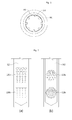
FIGS.7a and 7b are sectional views showing perforated orifices and spray surfaces thereof in the water spray type desuperheater according to the present disclosure. -
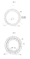
FIG.8 is a sectional view showing the circumferential arrangement of the spray holes of the perforated orifice and their perforated directions in the water spray type desuperheater according to the present disclosure. -
FIG.9 is a sectional view showing spray hole size adjusting means in the water spray type desuperheater according to the present disclosure. - Hereinafter, an explanation on a water spray type desuperheater according to the present disclosure will be in detail given with reference to the attached drawings.
-
FIG.2 is a sectional view showing main components of a water spray type desuperheater according to the present disclosure, andFIGS.3 and4 are sectional views showing examples of a spray tube of the water spray type desuperheater according to the present disclosure. - As shown in
FIGS. 2 to 4 , adesuperheating tube 300 is hollow at the inside thereof, through which superheated steam is moved. When a direction along which steam moves is divided into front and rear sides, a steam discharge portion a is defined as the front side of thedesuperheating tube 300, and a steam introduction portion d is as the rear side thereof. - One end of the
desuperheating tube 300 becomes the steam introduction portion d into which the superheated steam is introduced from another tube and the other end thereof becomes the steam discharge portion a from which air is discharged. Both ends of thedesuperheating tube 300 are configured in such a manner as to be easily fastened to other tubes. - One end of a
spray tube 100 is inserted from one side of thedesuperheating tube 300 into thedesuperheating tube 300. Preferably the one end of thespray tube 100 is inserted vertically downwardly from the top of thedesuperheating tube 300 into thedesuperheating tube 300. At this time, if thespray tube 100 is too deeply inserted into thedesuperheating tube 300, the flow of the steam is hindered, and contrarily, if thespray tube 100 is too closely inserted thereinto, the effect of spraying water upward is decreased, so that thespray tube 100 is desirably inserted into thedesuperheating tube 300 in such a manner as to allow spraying means of thespray tube 100 to be located at the center of the vertical section of thedesuperheating tube 300. - The interior of the
desuperheating tube 300 includes means for accelerating the introduced steam, preferablyventuri portions spray tube 100 inserted into thedesuperheating tube 300 so as to conduct the acceleration of the steam. Thus theventuri portions venturi portions FIG.2 , theventuri portions sleeve 200 in the interior of thedesuperheating tube 300, and in this case, the passage formed at one side of the intermediate portion of thesleeve 200 becomes narrow. Theventuri portions sleeve 200, and in addition thereto, a venturi passage may be formed in the interior of thedesuperheating tube 300. - The
neck portion 220 of theventuri portions neck portion 220, the flow rate of the superheated steam is increased, thus allowing the sprayed water to be atomized into fine particles and also permitting the evaporation of low temperature sprayed water to be accelerated, so that the sprayed water can be actively mixed with the superheated steam. - On the other hand, the
sleeve 200 may be proposed in a venturi or linear form in accordance with the embodiments of the present disclosure. That is, thespray tube 100 as will be discussed later and the components thereof may be located at thelinear sleeve 200. - As shown in
FIGS.5 and6 ,protrusions 250 orvanes 240 are desirably formed along the inner peripheral wall of thedesuperheating tube 300 or thesleeve 200 in the space (between c and d inFIG.2 ) between the steam introduction portion d and thespray tube 100 so as to allow the moving superheated steam to be mixed actively with the sprayed water through the formation of vortexes. - On the other hand, the
spray tube 100 is desirably formed of a cylindrical tube connected to a cooling water supply tube on the top end periphery thereof and closed at the bottom end periphery thereof. The bottom end periphery of thespray tube 100 is flat or semi-spherical, without any limitation thereto. - As shown in
FIGS.3 and4 , thespray tube 100 includes spray means formed on the lower end periphery thereof to spray water into thedesuperheating tube 300. In conventional practice, thespray tube 100 makes use of a spray nozzle as the spray means, but according to the present disclosure, thespray tube 100 forms anorifice 110 as the spray means, as shown inFIG.3 . - So as to more accelerate the mixing action, as shown in
FIG.4 , the spray means includes perforated orifices 120 each having a plurality of spray holes 121. When water is sprayed through the perforated orifices 120, the surface of water contacted with the steam is enlarged, and further, the water is sprayed more uniformly, thus allowing the mixing action between the water and the steam to be more accelerated. - On the other hand, as shown in
FIGS.7a and 7b , each perforated orifice 120 has the plurality of spray holes 121. The plurality of spray holes 121 is formed distributed on a given area of the outer peripheral surface of thespray tube 100, and the given area is defined as a spray surface, which is indicated by the dotted line inFIGS.7a and 7b . - Of course, one or more spray surfaces may be formed and distributed in various arrangements, but in this case, the spray surfaces desirably take a shape of a circle or rectangle with reference to the development figure of the circumferential surface of the
spray tube 100. Moreover, the spray surfaces or the distribution of the spray holes 121 might be adapted to the shape of the streaming superheated steam in the acceleration means, i.e. adapted to the shape of the venturi portions or the shape of the linear sleeve. - The spray means includes at least one or more perforated orifices 120. The perforated orifices 120 are formed in various arrangements, but so as to minimize a bending moment, as shown in
FIG.4 , the perforated orifices 120 are spaced apart from each other up and down with reference to the inserted portion of thespray tube 100 into thedesuperheating tube 300. - Referring to the vertical section of the
spray tube 100 as shown inFIG.8 , the spray holes 121 are perforated radially on the front side of the circumferential surface of thespray tube 100, and the perforated directions of the spray holes 121 are located toward the center of the circumference of thespray tube 100. The radial perforation of the spray holes 121 enables the water to be sprayed into a larger space than linear perforation of the spray holes 121. As shown inFIG.8 , θ is in the range of 0° to 90° , and θ of more than 90° is not desirable. - Further, the spray holes 121 may be perforated radially on the front surface of the circumferential surface of the
spray tube 100, that is, over the semi-circumferential surface thereof, and otherwise, they may be formed on a portion of the front surface of the circumferential surface of thespray tube 100. - As shown in
FIGS.7a and 7b , desirably, the spray holes 121 of the perforated orifice 120 become increased in diameters as they go from the lower peripheral surface of thespray tube 100 toward the upper peripheral surface of thespray tube 100. Further, when the spray holes 121 are formed on the plurality of perforated orifices 120 arranged up and down as well as on one perforated orifice 120, the spray holes 121 become increased in diameters as they go from the lower peripheral surface of thespray tube 100 toward the upper peripheral surface of thespray tube 100. - As a result, when the sprayed water through the spray holes 121 is moved to the
desuperheating tube 300, the sprayed water through the upper side spray holes 121 is moved with the moving time and distance heat-exchanged with the surrounding superheated steam more increased than that through the lower side spray holes 121, under the effect of gravity. If the particles of the sprayed water are large, generally, the desuperheating efficiency is high, but the mixing efficiency with the steam is lowered. According to the present disclosure, however, the diameters of the spray holes 121 become increased upward, thus enhancing both of the desuperheating efficiency and the mixing efficiency. - Further, spray hole size adjusting means is desirably located to adjust the sizes of the spray holes 121. That is, the spray hole size adjusting means is adapted to adjust the sizes of the spray holes 121, thus enabling adequate operations to be performed in accordance with the temperatures of the superheated steam.
- If the temperature of the superheated steam is so high, the sizes of the spray holes 121 become enlarged through the spray hole size adjusting means, thus allowing the amount of water sprayed and the particle sizes of water sprayed to be increased. If the sizes of the spray holes 121 are limitedly defined, generally, the spray pressure is enhanced to allow the amount of water sprayed to be partially increased, but since there is a limit in the increment of the particle sizes of water sprayed, the increment of the amount of water sprayed is also limited.
- If the temperature of the superheated steam is not high, to the contrary, the sizes of the spray holes 121 become reduced through the spray hole size adjusting means, thus allowing the amount of water sprayed and the particle sizes of water sprayed to be decreased. Generally, the mixing efficiency is not high if the temperature of the superheated steam is not high, and accordingly, even though the amount of water sprayed is reduced, there is a high possibility that droplets occur. According to the present disclosure, however, the particle sizes of the water sprayed are reduced to enhance the mixing efficiency with the steam, thus preventing the problems caused by the generation of droplets. Here, by use of the spray hole size adjusting means it is possible to close the spray holes to prevent spraying of remaining water introduced into the spray tube to avoid occurrence of droplets in case of low temperature of the steam.
- As shown in
FIG.9 , an opening/closing adjusting tube 101 is provided inside thespray tube 100, and the opening/closing adjusting tube 101 has a smaller diameter than thespray tube 100 in such a manner as to be open on the end thereof. Thus, by rotating the opening/closing adjusting tube 101 inside the spray tube the spray hole size can by adjusted or controlled. - The opening/
closing adjusting tube 101 is brought into contact with thespray tube 100 and includes spray holes 122 formed on the circumferential surface thereof in the same shapes as the spray holes 121 of thespray tube 100. - As the opening/
closing adjusting tube 101 is turned through rotating means, the opening/closing degrees of the spray holes 121 of thespray tube 100 are adjusted. - When the spray holes 121 of the
spray tube 100 are laid completely upon the spray holes 122 of the opening/closing adjusting tube 101, the spray holes 121 are open to the maximum degree, and when the spray holes 121 of thespray tube 100 alternate completely with the spray holes 122 of the opening/closing adjusting tube 101, the spray holes 121 are open to the minimum degree. - Further, the top end periphery of the opening/
closing adjusting tube 101 is connected to rotary means like a valve or actuator so as to control the degree of rotation thereof. - Furthermore, by using the opening/
closing adjusting tube 101 having many different spray areas with spray holes it is possible to provide a maximum of spray hole sizes to adapt the spraying amount of water to the temperature of the steam. Thus the opening/closing adjusting tube 101 might have spray area having spray holes with similar sizes as the spray holes of the spray tube to have a maximum water throughput. Furthermore, it might have a spray area having spray holes with reduced spray hole diameters only to provide a medium water throughput and it might have a closed spray area to close the spray holes of the spray tube completely. Thus, e.g. three possible opening degrees are provided, which could be further varied by half or partial overlap of the spray holes of the opening/closing adjusting tube 101 with the spray holes of the spray tube. Thus, by varying the rotation angle of the opening/closing adjusting tube 101 inside the spray tube it is possible to achieve many opening degrees of the spray holes. By use of different spray areas as described above a simple actuator for rotating the opening/closing adjusting tube 101 could be used. - The position relations of the components according to the present disclosure are described with reference to the attached drawings, and therefore, they may be varied in accordance with the various aspects of the present disclosure. The terms used herein are defined in accordance with the functions of the present disclosure, but may be varied under the intention or regulation of a user or operator. Therefore, they should be defined on the basis of the whole scope of the present disclosure. While the present disclosure has been described with reference to the particular illustrative embodiments, it is not to be restricted by the embodiments but only by the appended claims. It is to be appreciated that those skilled in the art can change or modify the embodiments without departing from the scope of the present disclosure.
Claims (15)
- A water spray type desuperheater comprising:a desuperheating tube (300) adapted to move superheated steam therealong and to conduct a mixing operation of mixing the superheated steam and water;acceleration means (210, 220, 230) inside the desuperheating tube (300) to accelerate the moving superheated steam;a spray tube (100) inserted from one side of the desuperheating tube (300) into the desuperheating tube (300) to introduce the water into the desuperheating tube (300).
- The water spray type desuperheater as claimed in claim 1, wherein the desuperheating tube (300) comprises venturi portions (210, 220 and 230) formed thereon in front of the spray tube (100) to conduct the acceleration of the moving speed of the superheated steam
- The water spray type desuperheater as claimed in claim 1, wherein the desuperheating tube (300) comprises a linear sleeve (200) disposed at the inside thereof to prevent the generation of pressure drop therein,
- The water spray type desuperheater as claimed in any one of the preceding claims, wherein the spray tube (100) comprises spray means formed on the portion inserted into the desuperheating tube (300) to spray the water into the desuperheating tube (300), the spray means having at least one or more orifices (110).
- The water spray type desuperheater according to claim 4, wherein the orifices (110) comprise at least one or more perforated orifices (120) each having a plurality of spray holes (121).
- The water spray type desuperheater as claimed in any one of the preceding claims, wherein the desuperheating tube (300) comprises vanes (240) and/or protrusions (250) formed in the space between a steam introduction portion (d) thereof and the spray tube (100) so as to form vortexes thereinto.
- The water spray type desuperheater according to claim 5, wherein each perforated orifice (120) comprises a spray surface on which the plurality of spray holes (121) is formed distributed on a given area of the outer peripheral surface of the spray tube (100).
- The water spray type desuperheater according to claim 7, wherein the perforated orifices (120) are spaced apart from each other up and down on the lower portion of the spray tube (100), and the spray surfaces of the perforated orifices (120) are spaced apart from each other as independent areas of each other.
- The water spray type desuperheater according to any one of claims 7 or 8, wherein the spray surfaces of the perforated orifices (120) take a shape of a circle or rectangle with reference to the development figure of the circumferential surface of the spray tube (100).
- The water spray type desuperheater according to any one of the preceding claims, wherein the spray tube (100) takes a cylindrical shape, the plurality of spray holes (121) formed on the spray tube (100) is perforated radially on the front side of the circumferential surface of the spray tube (100), and the perforated directions of the spray holes (121) are located toward the center of the circumference of the spray tube (100).
- The water spray type desuperheater according to any one of the preceding claims, wherein the spray holes (121) of each perforated orifice (120) increase in diameter as the spray holes (121) go from the lower peripheral surface of the spray tube (100) toward the upper peripheral surface of the spray tube (100).
- The water spray type desuperheater according to any one of the preceding claims, wherein the spray tube (100) further comprises an opening/closing adjusting tube (101) located at the inside thereof, the opening/closing adjusting tube (101) having a smaller diameter than the spray tube (100) in such a manner as to be open on the end thereof, and the outer peripheral surface of the opening/closing adjusting tube (101) is brought into contact with the inner peripheral surface of the spray tube (100), the opening/closing adjusting tube 101 having a plurality of spray holes (122) formed on the circumferential surface thereof in such a manner as to correspond to the plurality of the spray holes (121) of the spray tube (100) and being turned by means of rotating means to adjust the opening/closing degrees of the spray holes (121) of the spray tube (100).
- A desuperheating method comprising the steps of:introducing superheated steam from a steam introduction portion (d) of a desuperheater into a desuperheating tube (300) of the desuperheater;moving the superheated steam along the interior of the desuperheating tube (300);accelerating the moving steam by acceleration means inside the desuperheating tube (300);supplying water to the interior of a stray tube (100);spraying the water supplied to the spray tube (100) through orifices (110);mixing the superheated steam and the sprayed water in the desuperheating tube (300); anddischarging the desuperheated steam through a steam discharge portion (a) of the desuperheater.
- The desuperheating method according to claim 13, wherein the step of mixing the superheated steam and the sprayed water is conducted by accelerating the flow of the superheated steam and the sprayed water from perforated orifices (120) through venturi portions (210, 220 and 230) formed on the desuperheating tube (300) in front of the spray tube (100) and by increasing the mixing speed of the superheated steam and the sprayed water.
- The desuperheating method according to claim 13 or 14, wherein the superheated steam in the step of moving the superheated steam along the desuperheating tube (300) is passed through protrusions (250) and/or vanes (240) formed on the desuperheating tube (300) in the space between the steam introduction portion (d) and the spray tube (100) and forming vortexes in the desuperheating tube (300).
Applications Claiming Priority (2)
| Application Number | Priority Date | Filing Date | Title |
|---|---|---|---|
| KR1020140036860A KR101538626B1 (en) | 2014-03-28 | 2014-03-28 | a device of water spray type desuperheater and a method thereof |
| KR1020140036957A KR101538621B1 (en) | 2014-03-28 | 2014-03-28 | a device of water spray type desuperheater and a method thereof |
Publications (2)
| Publication Number | Publication Date |
|---|---|
| EP2924356A1 true EP2924356A1 (en) | 2015-09-30 |
| EP2924356B1 EP2924356B1 (en) | 2017-07-26 |
Family
ID=52780890
Family Applications (1)
| Application Number | Title | Priority Date | Filing Date |
|---|---|---|---|
| EP15161277.7A Active EP2924356B1 (en) | 2014-03-28 | 2015-03-27 | Water spray type desuperheater and desuperheating method |
Country Status (3)
| Country | Link |
|---|---|
| EP (1) | EP2924356B1 (en) |
| JP (1) | JP6427815B2 (en) |
| CN (1) | CN104949103B (en) |
Cited By (3)
| Publication number | Priority date | Publication date | Assignee | Title |
|---|---|---|---|---|
| CN111174019A (en) * | 2019-12-31 | 2020-05-19 | 浙江大学 | A device and method for coordinated regulation of steam pressure and temperature |
| CN112892894A (en) * | 2019-12-03 | 2021-06-04 | 费希尔控制产品国际有限公司 | Spray head for use with a desuperheater and desuperheater including such a spray head |
| US12485304B2 (en) | 2021-08-31 | 2025-12-02 | Marioff Corporation Oy | Fire suppression sprinkler device |
Families Citing this family (4)
| Publication number | Priority date | Publication date | Assignee | Title |
|---|---|---|---|---|
| JP7403784B2 (en) * | 2018-09-20 | 2023-12-25 | 株式会社テイエルブイ | Steam detemperature system |
| US11346545B2 (en) | 2018-11-09 | 2022-05-31 | Fisher Controls International Llc | Spray heads for use with desuperheaters and desuperheaters including such spray heads |
| CN112676054A (en) * | 2020-12-17 | 2021-04-20 | 青岛科技大学 | Vortex guide type supersonic flame spraying spray gun device |
| CN115899025A (en) * | 2022-10-08 | 2023-04-04 | 吉林大学 | Condition self-adaptive distributed micro-channel integrated heat dissipation system, heat dissipation method and construction machinery |
Citations (3)
| Publication number | Priority date | Publication date | Assignee | Title |
|---|---|---|---|---|
| US2550683A (en) * | 1946-08-17 | 1951-05-01 | Babcock & Wilcox Co | Attemperator |
| DE3415086C1 (en) * | 1984-04-21 | 1985-11-07 | Reglerbau Hannemann GmbH & Co KG, 1000 Berlin | Ball valve |
| JP2000291907A (en) * | 1999-04-06 | 2000-10-20 | Ishikawajima Harima Heavy Ind Co Ltd | spray nozzle |
Family Cites Families (15)
| Publication number | Priority date | Publication date | Assignee | Title |
|---|---|---|---|---|
| US4130611A (en) * | 1976-12-06 | 1978-12-19 | Yarway Corporation | Attemperator |
| JPS60196108U (en) * | 1984-06-05 | 1985-12-27 | 石川島播磨重工業株式会社 | Boiler steam temperature control nozzle |
| JPH064170Y2 (en) * | 1984-07-23 | 1994-02-02 | バブコツク日立株式会社 | Desuperheater |
| CN2032677U (en) * | 1988-04-15 | 1989-02-15 | 机械工业委员会上海发电设备成套设计研究所 | Venturi tube spray desuperheater |
| JPH0314519U (en) * | 1989-06-16 | 1991-02-14 | ||
| JPH07158814A (en) * | 1993-12-06 | 1995-06-20 | Hitachi Ltd | Spray type superheat reducer |
| JPH09303709A (en) * | 1996-05-13 | 1997-11-28 | Ishikawajima Harima Heavy Ind Co Ltd | Overheat reducer |
| JP3948097B2 (en) * | 1998-02-19 | 2007-07-25 | 石川島播磨重工業株式会社 | Boiler overheat reducer |
| JP4058681B2 (en) * | 2002-08-28 | 2008-03-12 | バブコック日立株式会社 | Overheat reducer |
| JP2005273952A (en) * | 2004-03-23 | 2005-10-06 | Babcock Hitachi Kk | Desuperheater |
| CN201844390U (en) * | 2010-11-02 | 2011-05-25 | 肥城白庄煤矿有限公司 | Water spray desuperheater |
| CN202303340U (en) * | 2011-11-02 | 2012-07-04 | 哈尔滨锅炉厂有限责任公司 | 600 MW boiler superheater desuperheater |
| CN202470032U (en) * | 2012-02-15 | 2012-10-03 | 河北省电力勘测设计研究院 | Variable-flow high-speed attemperator nozzle |
| CN202769637U (en) * | 2012-06-22 | 2013-03-06 | 上海锅炉厂有限公司 | Composite bushing type direct contact desuperheater |
| CN202791982U (en) * | 2012-07-19 | 2013-03-13 | 无锡华光锅炉股份有限公司 | Positioning device for liner mixing tube of desuperheater |
-
2015
- 2015-03-27 JP JP2015067407A patent/JP6427815B2/en active Active
- 2015-03-27 CN CN201510141228.7A patent/CN104949103B/en active Active
- 2015-03-27 EP EP15161277.7A patent/EP2924356B1/en active Active
Patent Citations (3)
| Publication number | Priority date | Publication date | Assignee | Title |
|---|---|---|---|---|
| US2550683A (en) * | 1946-08-17 | 1951-05-01 | Babcock & Wilcox Co | Attemperator |
| DE3415086C1 (en) * | 1984-04-21 | 1985-11-07 | Reglerbau Hannemann GmbH & Co KG, 1000 Berlin | Ball valve |
| JP2000291907A (en) * | 1999-04-06 | 2000-10-20 | Ishikawajima Harima Heavy Ind Co Ltd | spray nozzle |
Cited By (3)
| Publication number | Priority date | Publication date | Assignee | Title |
|---|---|---|---|---|
| CN112892894A (en) * | 2019-12-03 | 2021-06-04 | 费希尔控制产品国际有限公司 | Spray head for use with a desuperheater and desuperheater including such a spray head |
| CN111174019A (en) * | 2019-12-31 | 2020-05-19 | 浙江大学 | A device and method for coordinated regulation of steam pressure and temperature |
| US12485304B2 (en) | 2021-08-31 | 2025-12-02 | Marioff Corporation Oy | Fire suppression sprinkler device |
Also Published As
| Publication number | Publication date |
|---|---|
| JP2015190757A (en) | 2015-11-02 |
| JP6427815B2 (en) | 2018-11-28 |
| CN104949103A (en) | 2015-09-30 |
| EP2924356B1 (en) | 2017-07-26 |
| CN104949103B (en) | 2017-09-19 |
Similar Documents
| Publication | Publication Date | Title |
|---|---|---|
| EP2924356B1 (en) | Water spray type desuperheater and desuperheating method | |
| EP3241751A1 (en) | Dimpled nacelle inner-surface for heat transfer improvement | |
| EP2998137A1 (en) | Heat exchanger distributor with intersecting streams | |
| EP0700497B1 (en) | Improved steam desuperheater | |
| CN110929460B (en) | Flow field optimization method and system for desulfurization wastewater zero-emission flue evaporation process | |
| US9452438B2 (en) | Full cone spray nozzle | |
| CN205592935U (en) | Steam cooler | |
| US6691929B1 (en) | Closed-vortex-assisted desuperheater | |
| KR101538621B1 (en) | a device of water spray type desuperheater and a method thereof | |
| CN106091722A (en) | A kind of plant condenser moisturizing atomization system | |
| US20090008805A1 (en) | Air Disperser for a Spray Dryer and a Method for Designing an Air Disperser | |
| KR101538626B1 (en) | a device of water spray type desuperheater and a method thereof | |
| WO2015045835A1 (en) | Burner tip, combustion burner, and boiler | |
| CN109827461A (en) | A centrifugal swirl hollow nozzle device suitable for a counter-flow cooling tower of an air-conditioning system | |
| JP6525607B2 (en) | Low temperature liquefied gas vaporizer | |
| CN211040931U (en) | Atomizing nozzle and deaerator | |
| JP5928078B2 (en) | Rotary kiln cooling system | |
| JP4427474B2 (en) | Temperature reduction tower | |
| JP6699900B2 (en) | Rectifier | |
| Dobrego et al. | Use of oriented spray nozzles to set the vapor–air flow in rotary motion in the superspray space of the evaporative chimney-type tower | |
| JP6099492B2 (en) | Dry cooling device and exhaust gas cooling method using the same | |
| JP2017040459A (en) | Heat source unit of refrigeration device | |
| JP2015127595A (en) | Air conditioner outdoor unit | |
| CN110410770B (en) | Atomizing nozzle and deaerator | |
| JP5087509B2 (en) | Temperature reduction tower |
Legal Events
| Date | Code | Title | Description |
|---|---|---|---|
| PUAI | Public reference made under article 153(3) epc to a published international application that has entered the european phase |
Free format text: ORIGINAL CODE: 0009012 |
|
| 17P | Request for examination filed |
Effective date: 20150408 |
|
| AK | Designated contracting states |
Kind code of ref document: A1 Designated state(s): AL AT BE BG CH CY CZ DE DK EE ES FI FR GB GR HR HU IE IS IT LI LT LU LV MC MK MT NL NO PL PT RO RS SE SI SK SM TR |
|
| AX | Request for extension of the european patent |
Extension state: BA ME |
|
| RBV | Designated contracting states (corrected) |
Designated state(s): AL AT BE BG CH CY CZ DE DK EE ES FI FR GB GR HR HU IE IS IT LI LT LU LV MC MK MT NL NO PL PT RO RS SE SI SK SM TR |
|
| RIC1 | Information provided on ipc code assigned before grant |
Ipc: F22G 5/12 20060101AFI20170130BHEP |
|
| GRAP | Despatch of communication of intention to grant a patent |
Free format text: ORIGINAL CODE: EPIDOSNIGR1 |
|
| INTG | Intention to grant announced |
Effective date: 20170324 |
|
| GRAS | Grant fee paid |
Free format text: ORIGINAL CODE: EPIDOSNIGR3 |
|
| GRAA | (expected) grant |
Free format text: ORIGINAL CODE: 0009210 |
|
| AK | Designated contracting states |
Kind code of ref document: B1 Designated state(s): AL AT BE BG CH CY CZ DE DK EE ES FI FR GB GR HR HU IE IS IT LI LT LU LV MC MK MT NL NO PL PT RO RS SE SI SK SM TR |
|
| REG | Reference to a national code |
Ref country code: GB Ref legal event code: FG4D |
|
| REG | Reference to a national code |
Ref country code: CH Ref legal event code: EP |
|
| REG | Reference to a national code |
Ref country code: AT Ref legal event code: REF Ref document number: 912687 Country of ref document: AT Kind code of ref document: T Effective date: 20170815 |
|
| REG | Reference to a national code |
Ref country code: IE Ref legal event code: FG4D |
|
| REG | Reference to a national code |
Ref country code: DE Ref legal event code: R096 Ref document number: 602015003705 Country of ref document: DE |
|
| REG | Reference to a national code |
Ref country code: NL Ref legal event code: MP Effective date: 20170726 |
|
| REG | Reference to a national code |
Ref country code: LT Ref legal event code: MG4D |
|
| REG | Reference to a national code |
Ref country code: AT Ref legal event code: MK05 Ref document number: 912687 Country of ref document: AT Kind code of ref document: T Effective date: 20170726 |
|
| PG25 | Lapsed in a contracting state [announced via postgrant information from national office to epo] |
Ref country code: SE Free format text: LAPSE BECAUSE OF FAILURE TO SUBMIT A TRANSLATION OF THE DESCRIPTION OR TO PAY THE FEE WITHIN THE PRESCRIBED TIME-LIMIT Effective date: 20170726 Ref country code: LT Free format text: LAPSE BECAUSE OF FAILURE TO SUBMIT A TRANSLATION OF THE DESCRIPTION OR TO PAY THE FEE WITHIN THE PRESCRIBED TIME-LIMIT Effective date: 20170726 Ref country code: FI Free format text: LAPSE BECAUSE OF FAILURE TO SUBMIT A TRANSLATION OF THE DESCRIPTION OR TO PAY THE FEE WITHIN THE PRESCRIBED TIME-LIMIT Effective date: 20170726 Ref country code: AT Free format text: LAPSE BECAUSE OF FAILURE TO SUBMIT A TRANSLATION OF THE DESCRIPTION OR TO PAY THE FEE WITHIN THE PRESCRIBED TIME-LIMIT Effective date: 20170726 Ref country code: HR Free format text: LAPSE BECAUSE OF FAILURE TO SUBMIT A TRANSLATION OF THE DESCRIPTION OR TO PAY THE FEE WITHIN THE PRESCRIBED TIME-LIMIT Effective date: 20170726 Ref country code: NO Free format text: LAPSE BECAUSE OF FAILURE TO SUBMIT A TRANSLATION OF THE DESCRIPTION OR TO PAY THE FEE WITHIN THE PRESCRIBED TIME-LIMIT Effective date: 20171026 Ref country code: NL Free format text: LAPSE BECAUSE OF FAILURE TO SUBMIT A TRANSLATION OF THE DESCRIPTION OR TO PAY THE FEE WITHIN THE PRESCRIBED TIME-LIMIT Effective date: 20170726 |
|
| REG | Reference to a national code |
Ref country code: FR Ref legal event code: PLFP Year of fee payment: 4 |
|
| PG25 | Lapsed in a contracting state [announced via postgrant information from national office to epo] |
Ref country code: GR Free format text: LAPSE BECAUSE OF FAILURE TO SUBMIT A TRANSLATION OF THE DESCRIPTION OR TO PAY THE FEE WITHIN THE PRESCRIBED TIME-LIMIT Effective date: 20171027 Ref country code: BG Free format text: LAPSE BECAUSE OF FAILURE TO SUBMIT A TRANSLATION OF THE DESCRIPTION OR TO PAY THE FEE WITHIN THE PRESCRIBED TIME-LIMIT Effective date: 20171026 Ref country code: LV Free format text: LAPSE BECAUSE OF FAILURE TO SUBMIT A TRANSLATION OF THE DESCRIPTION OR TO PAY THE FEE WITHIN THE PRESCRIBED TIME-LIMIT Effective date: 20170726 Ref country code: RS Free format text: LAPSE BECAUSE OF FAILURE TO SUBMIT A TRANSLATION OF THE DESCRIPTION OR TO PAY THE FEE WITHIN THE PRESCRIBED TIME-LIMIT Effective date: 20170726 Ref country code: IS Free format text: LAPSE BECAUSE OF FAILURE TO SUBMIT A TRANSLATION OF THE DESCRIPTION OR TO PAY THE FEE WITHIN THE PRESCRIBED TIME-LIMIT Effective date: 20171126 Ref country code: ES Free format text: LAPSE BECAUSE OF FAILURE TO SUBMIT A TRANSLATION OF THE DESCRIPTION OR TO PAY THE FEE WITHIN THE PRESCRIBED TIME-LIMIT Effective date: 20170726 Ref country code: PL Free format text: LAPSE BECAUSE OF FAILURE TO SUBMIT A TRANSLATION OF THE DESCRIPTION OR TO PAY THE FEE WITHIN THE PRESCRIBED TIME-LIMIT Effective date: 20170726 |
|
| PG25 | Lapsed in a contracting state [announced via postgrant information from national office to epo] |
Ref country code: CZ Free format text: LAPSE BECAUSE OF FAILURE TO SUBMIT A TRANSLATION OF THE DESCRIPTION OR TO PAY THE FEE WITHIN THE PRESCRIBED TIME-LIMIT Effective date: 20170726 Ref country code: RO Free format text: LAPSE BECAUSE OF FAILURE TO SUBMIT A TRANSLATION OF THE DESCRIPTION OR TO PAY THE FEE WITHIN THE PRESCRIBED TIME-LIMIT Effective date: 20170726 Ref country code: DK Free format text: LAPSE BECAUSE OF FAILURE TO SUBMIT A TRANSLATION OF THE DESCRIPTION OR TO PAY THE FEE WITHIN THE PRESCRIBED TIME-LIMIT Effective date: 20170726 |
|
| REG | Reference to a national code |
Ref country code: DE Ref legal event code: R097 Ref document number: 602015003705 Country of ref document: DE |
|
| PG25 | Lapsed in a contracting state [announced via postgrant information from national office to epo] |
Ref country code: IT Free format text: LAPSE BECAUSE OF FAILURE TO SUBMIT A TRANSLATION OF THE DESCRIPTION OR TO PAY THE FEE WITHIN THE PRESCRIBED TIME-LIMIT Effective date: 20170726 Ref country code: SM Free format text: LAPSE BECAUSE OF FAILURE TO SUBMIT A TRANSLATION OF THE DESCRIPTION OR TO PAY THE FEE WITHIN THE PRESCRIBED TIME-LIMIT Effective date: 20170726 Ref country code: EE Free format text: LAPSE BECAUSE OF FAILURE TO SUBMIT A TRANSLATION OF THE DESCRIPTION OR TO PAY THE FEE WITHIN THE PRESCRIBED TIME-LIMIT Effective date: 20170726 Ref country code: SK Free format text: LAPSE BECAUSE OF FAILURE TO SUBMIT A TRANSLATION OF THE DESCRIPTION OR TO PAY THE FEE WITHIN THE PRESCRIBED TIME-LIMIT Effective date: 20170726 |
|
| PLBE | No opposition filed within time limit |
Free format text: ORIGINAL CODE: 0009261 |
|
| STAA | Information on the status of an ep patent application or granted ep patent |
Free format text: STATUS: NO OPPOSITION FILED WITHIN TIME LIMIT |
|
| 26N | No opposition filed |
Effective date: 20180430 |
|
| PG25 | Lapsed in a contracting state [announced via postgrant information from national office to epo] |
Ref country code: SI Free format text: LAPSE BECAUSE OF FAILURE TO SUBMIT A TRANSLATION OF THE DESCRIPTION OR TO PAY THE FEE WITHIN THE PRESCRIBED TIME-LIMIT Effective date: 20170726 |
|
| REG | Reference to a national code |
Ref country code: CH Ref legal event code: PL |
|
| PG25 | Lapsed in a contracting state [announced via postgrant information from national office to epo] |
Ref country code: MC Free format text: LAPSE BECAUSE OF FAILURE TO SUBMIT A TRANSLATION OF THE DESCRIPTION OR TO PAY THE FEE WITHIN THE PRESCRIBED TIME-LIMIT Effective date: 20170726 |
|
| REG | Reference to a national code |
Ref country code: BE Ref legal event code: MM Effective date: 20180331 |
|
| REG | Reference to a national code |
Ref country code: IE Ref legal event code: MM4A |
|
| PG25 | Lapsed in a contracting state [announced via postgrant information from national office to epo] |
Ref country code: LU Free format text: LAPSE BECAUSE OF NON-PAYMENT OF DUE FEES Effective date: 20180327 |
|
| PG25 | Lapsed in a contracting state [announced via postgrant information from national office to epo] |
Ref country code: IE Free format text: LAPSE BECAUSE OF NON-PAYMENT OF DUE FEES Effective date: 20180327 |
|
| PG25 | Lapsed in a contracting state [announced via postgrant information from national office to epo] |
Ref country code: BE Free format text: LAPSE BECAUSE OF NON-PAYMENT OF DUE FEES Effective date: 20180331 Ref country code: CH Free format text: LAPSE BECAUSE OF NON-PAYMENT OF DUE FEES Effective date: 20180331 Ref country code: LI Free format text: LAPSE BECAUSE OF NON-PAYMENT OF DUE FEES Effective date: 20180331 |
|
| PG25 | Lapsed in a contracting state [announced via postgrant information from national office to epo] |
Ref country code: MT Free format text: LAPSE BECAUSE OF NON-PAYMENT OF DUE FEES Effective date: 20180327 |
|
| PG25 | Lapsed in a contracting state [announced via postgrant information from national office to epo] |
Ref country code: TR Free format text: LAPSE BECAUSE OF FAILURE TO SUBMIT A TRANSLATION OF THE DESCRIPTION OR TO PAY THE FEE WITHIN THE PRESCRIBED TIME-LIMIT Effective date: 20170726 |
|
| PG25 | Lapsed in a contracting state [announced via postgrant information from national office to epo] |
Ref country code: PT Free format text: LAPSE BECAUSE OF FAILURE TO SUBMIT A TRANSLATION OF THE DESCRIPTION OR TO PAY THE FEE WITHIN THE PRESCRIBED TIME-LIMIT Effective date: 20170726 |
|
| PG25 | Lapsed in a contracting state [announced via postgrant information from national office to epo] |
Ref country code: CY Free format text: LAPSE BECAUSE OF FAILURE TO SUBMIT A TRANSLATION OF THE DESCRIPTION OR TO PAY THE FEE WITHIN THE PRESCRIBED TIME-LIMIT Effective date: 20170726 Ref country code: HU Free format text: LAPSE BECAUSE OF FAILURE TO SUBMIT A TRANSLATION OF THE DESCRIPTION OR TO PAY THE FEE WITHIN THE PRESCRIBED TIME-LIMIT; INVALID AB INITIO Effective date: 20150327 Ref country code: MK Free format text: LAPSE BECAUSE OF NON-PAYMENT OF DUE FEES Effective date: 20170726 |
|
| PG25 | Lapsed in a contracting state [announced via postgrant information from national office to epo] |
Ref country code: AL Free format text: LAPSE BECAUSE OF FAILURE TO SUBMIT A TRANSLATION OF THE DESCRIPTION OR TO PAY THE FEE WITHIN THE PRESCRIBED TIME-LIMIT Effective date: 20170726 |
|
| PGFP | Annual fee paid to national office [announced via postgrant information from national office to epo] |
Ref country code: DE Payment date: 20241231 Year of fee payment: 11 |
|
| PGFP | Annual fee paid to national office [announced via postgrant information from national office to epo] |
Ref country code: FR Payment date: 20250210 Year of fee payment: 11 |
|
| PGFP | Annual fee paid to national office [announced via postgrant information from national office to epo] |
Ref country code: GB Payment date: 20250102 Year of fee payment: 11 |