EP2924332A1 - Illumination device that switches light emission direction - Google Patents
Illumination device that switches light emission direction Download PDFInfo
- Publication number
- EP2924332A1 EP2924332A1 EP15160859.3A EP15160859A EP2924332A1 EP 2924332 A1 EP2924332 A1 EP 2924332A1 EP 15160859 A EP15160859 A EP 15160859A EP 2924332 A1 EP2924332 A1 EP 2924332A1
- Authority
- EP
- European Patent Office
- Prior art keywords
- unit
- main body
- assembly
- illumination device
- light
- Prior art date
- Legal status (The legal status is an assumption and is not a legal conclusion. Google has not performed a legal analysis and makes no representation as to the accuracy of the status listed.)
- Granted
Links
Images


Classifications
-
- F—MECHANICAL ENGINEERING; LIGHTING; HEATING; WEAPONS; BLASTING
- F21—LIGHTING
- F21V—FUNCTIONAL FEATURES OR DETAILS OF LIGHTING DEVICES OR SYSTEMS THEREOF; STRUCTURAL COMBINATIONS OF LIGHTING DEVICES WITH OTHER ARTICLES, NOT OTHERWISE PROVIDED FOR
- F21V17/00—Fastening of component parts of lighting devices, e.g. shades, globes, refractors, reflectors, filters, screens, grids or protective cages
- F21V17/02—Fastening of component parts of lighting devices, e.g. shades, globes, refractors, reflectors, filters, screens, grids or protective cages with provision for adjustment
-
- F—MECHANICAL ENGINEERING; LIGHTING; HEATING; WEAPONS; BLASTING
- F21—LIGHTING
- F21K—NON-ELECTRIC LIGHT SOURCES USING LUMINESCENCE; LIGHT SOURCES USING ELECTROCHEMILUMINESCENCE; LIGHT SOURCES USING CHARGES OF COMBUSTIBLE MATERIAL; LIGHT SOURCES USING SEMICONDUCTOR DEVICES AS LIGHT-GENERATING ELEMENTS; LIGHT SOURCES NOT OTHERWISE PROVIDED FOR
- F21K9/00—Light sources using semiconductor devices as light-generating elements, e.g. using light-emitting diodes [LED] or lasers
- F21K9/20—Light sources comprising attachment means
- F21K9/23—Retrofit light sources for lighting devices with a single fitting for each light source, e.g. for substitution of incandescent lamps with bayonet or threaded fittings
-
- F—MECHANICAL ENGINEERING; LIGHTING; HEATING; WEAPONS; BLASTING
- F21—LIGHTING
- F21K—NON-ELECTRIC LIGHT SOURCES USING LUMINESCENCE; LIGHT SOURCES USING ELECTROCHEMILUMINESCENCE; LIGHT SOURCES USING CHARGES OF COMBUSTIBLE MATERIAL; LIGHT SOURCES USING SEMICONDUCTOR DEVICES AS LIGHT-GENERATING ELEMENTS; LIGHT SOURCES NOT OTHERWISE PROVIDED FOR
- F21K9/00—Light sources using semiconductor devices as light-generating elements, e.g. using light-emitting diodes [LED] or lasers
- F21K9/60—Optical arrangements integrated in the light source, e.g. for improving the colour rendering index or the light extraction
- F21K9/65—Optical arrangements integrated in the light source, e.g. for improving the colour rendering index or the light extraction specially adapted for changing the characteristics or the distribution of the light, e.g. by adjustment of parts
-
- F—MECHANICAL ENGINEERING; LIGHTING; HEATING; WEAPONS; BLASTING
- F21—LIGHTING
- F21V—FUNCTIONAL FEATURES OR DETAILS OF LIGHTING DEVICES OR SYSTEMS THEREOF; STRUCTURAL COMBINATIONS OF LIGHTING DEVICES WITH OTHER ARTICLES, NOT OTHERWISE PROVIDED FOR
- F21V11/00—Screens not covered by groups F21V1/00, F21V3/00, F21V7/00 or F21V9/00
-
- F—MECHANICAL ENGINEERING; LIGHTING; HEATING; WEAPONS; BLASTING
- F21—LIGHTING
- F21V—FUNCTIONAL FEATURES OR DETAILS OF LIGHTING DEVICES OR SYSTEMS THEREOF; STRUCTURAL COMBINATIONS OF LIGHTING DEVICES WITH OTHER ARTICLES, NOT OTHERWISE PROVIDED FOR
- F21V21/00—Supporting, suspending, or attaching arrangements for lighting devices; Hand grips
- F21V21/14—Adjustable mountings
- F21V21/26—Pivoted arms
- F21V21/28—Pivoted arms adjustable in more than one plane
- F21V21/29—Pivoted arms adjustable in more than one plane employing universal joints
-
- F—MECHANICAL ENGINEERING; LIGHTING; HEATING; WEAPONS; BLASTING
- F21—LIGHTING
- F21Y—INDEXING SCHEME ASSOCIATED WITH SUBCLASSES F21K, F21L, F21S and F21V, RELATING TO THE FORM OR THE KIND OF THE LIGHT SOURCES OR OF THE COLOUR OF THE LIGHT EMITTED
- F21Y2115/00—Light-generating elements of semiconductor light sources
- F21Y2115/10—Light-emitting diodes [LED]
Definitions
- the present invention relates to an illumination device, and more particularly, to an illumination device that switches a light emission direction.
- an illumination device is used for ensuring the ability to see in a dark place or for displaying a visual effect for advertisement or aesthetic purposes.
- a light source for the illumination device may be an incandescent lamp, a fluorescent lamp, or a halogen lamp.
- LEDs light-emitting diodes
- LEDs are a kind of light-emitting device that produce light of various colors through changing of a compound semiconductor material, such as GaAs, AlGaAs, GaN, or InGaInP.
- LEDs have a long lifetime, may be miniaturized and manufactured to have a light weight, and may be driven at a low voltage due to high directionality. Also, LEDs have an excellent monochromatic peak wavelength, an excellent optical efficiency, and low power consumption, and are eco-friendly. Therefore, LEDs are widely used in various fields, such as TVs, computers, lighting, and automobiles, and its application fields are gradually expanded.
- An illumination device may need a function that the direction of light emitted from a light source is changed to a desired direction after the illumination device is installed.
- the light emission direction may be changed by using a direction changing member formed on the same structure on which the illumination device is installed or by changing the direction of a whole structure.
- One or more embodiments include an illumination device having an element that may change an emission direction of light emitted from a light source.
- an illumination device may include: an upper body on which a light-emitting unit that emits light may be mounted; a lower body that may provide a power path to the light-emitting unit; a conversion unit that may connect the upper body together and the lower body and may convert the emission direction of light emitted from the light-emitting unit of the upper body; and an assembly unit that may assemble the conversion unit to the upper body.
- the conversion unit may include a ball-shaped main body unit, the assembly unit may include a first assembly unit and a second assembly unit, and the first and second assembly units may rotate in a state of surrounding and contacting the main body unit.
- the conversion unit may include a tap formed by extending from the main body unit, and the tap may be coupled to the lower body by protruding downwards of the upper body.
- the conversion unit may include a ball-shaped upper main body and a lower main body, the lower main body may have a larger radius of curvature than that of the upper main body, and a step difference unit may be formed between the lower main body and the upper main body.
- At least one conversion control unit that protrudes from the second assembly unit may be formed on a lower surface of the second assembly unit, and the conversion control unit may contact or face an upper surface of the upper main body.
- the illumination device may further include at least one protrusion unit formed on the upper main body.
- the main body may include a first main body unit, a second main body unit, and a lower surface unit that may be formed between the first and second main body units.
- At least one conversion control unit that protrudes from the second assembly unit may be formed on a lower surface of the second assembly unit, and the conversion control unit may contact or face the lower surface unit.
- Edge portions that protrude on both sides of the first assembly unit may be supported by a first step difference unit formed of the upper body, and edge portions that protrude on both sides of the second assembly unit may be supported by a second step difference unit of the upper body.
- the second assembly unit and the second step difference unit of the upper body may be coupled by at least one assembling means.
- the light-emitting unit may be formed by mounting a plurality of diode chips on a substrate.
- a cover unit may be formed on the upper body, and the cover unit may be formed, for example, of glass, a ceramic material, a resin of polycarbonate (PC) group, a resin of polymethyl methacrylate (PMMA), or the like.
- PC polycarbonate
- PMMA polymethyl methacrylate
- the upper body may be formed as a housing structure having step differences so that the light-emitting unit and the first and second assembly units may be seated thereon.
- the lower body may include a socket unit to supply power to the light-emitting unit from the socket unit.
- Edge portions that protrude on both sides of the first assembly unit may be supported by the first step difference unit, and a first elastic member may be formed between the first assembly unit and the first step difference unit.
- the illumination device may further include a second elastic member formed between the second assembly unit and the light-emitting unit.
- the second elastic member may be formed as an O-ring and may include at least one coil spring.
- the illumination device may include an upper body 10, on which a light-emitting unit that emits light may be mounted, and a lower body 20 that may provide a power path for supplying power to the light-emitting unit and may be connected to another structure via a socket unit 50.
- a cover unit 40 may be formed on the upper body 10.
- a conversion unit 30 may be formed between the upper body 10 and the lower body 20. The conversion unit 30 may connect the upper body 10 and the lower body 20 together and may convert the direction of light emitted from the light-emitting unit.
- the lower body 20 may be fixed on an external structure, and the upper body 10 may rotate or tilt to a desired direction with the conversion unit 30 as a center of rotation.
- the upper body 10 may include an assembly unit, for example, first and second assembly units 110 and 120, and a light-emitting unit 150 may be mounted on the assembly unit.
- the assembly unit may include first and second assembly units 110 and 120, and the conversion unit 30 may be coupled between the first and second assembly units 110 and 120.
- a tap 32 which may be formed on the conversion unit 30, may protrude downwards in the upper body 10 through a through hole 112 of the first assembly unit 110, and thus, may connect the upper body 10 to the lower body 20 by being coupled to a coupling unit 22 of the lower body 20.
- FIG. 3 is a cross-sectional view of an assembled structure of an illumination device such as the illumination device of FIG. 1 , according to one or more embodiments.
- a step difference unit for example, first, second, and third step difference units 14a, 14b, and 14c, may be provided in the upper body 10 to support and seat the first and second assembly units 110 and 120, the conversion unit 30, and the light-emitting unit 150.
- Both edges that protrude on both sides of the first assembly unit 110 may be positioned on the upper body 10 by being supported by the first step difference unit 14a.
- a coupling means for example, an adhesive may be optionally used between the first assembly unit 110 and the upper body 10.
- the first assembly unit 110 may be seated on the upper body 10 without using an additional coupling means.
- the conversion unit 30 may be inserted into the through hole 112 in the first assembly unit 110, and the tap 32 formed on the conversion unit 30 may protrude outside, that is, downwards in the through hole 112 of the first assembly unit 110.
- the tap 32 of the conversion unit 30 may be coupled to the coupling unit 22 of the lower body 20, and spirals may be formed on surfaces of the tap 32 and the coupling unit 22 to correspond to each other and readily couple to each other.
- the second assembly unit 120 may be located on the first assembly unit 110 and the conversion unit 30, edge portions that protrude on both sides of the second assembly unit 120 may be supported by the second step difference unit 14b.
- a fastener 121 may be used between the second assembly unit 120 and the upper body 10, for example, the both edges of the second assembly unit 120 and the second step difference unit 14b may be coupled by the fastener 121 having a spiral formed thereon. Also, optionally, the both edges of the second assembly unit 120 and the second step difference unit 14b may be coupled by using an adhesive. More than one fastener 121 may be used between the second assembly unit 120 and the upper body 10. When a binding force between the second assembly unit 120 and the upper body 10 is weak, the second assembly unit 120 and the upper body 10 may be separated from each other.
- the conversion unit 30 may be moved upwards. Therefore, a plurality of fasteners 121 may be formed between the first and second assembly units 110 and 120 and the upper body 10.
- the first and second assembly units 110 and 120 may both surround and contact the ball-shaped conversion unit 30 and may rotate with the conversion unit 30 as a center of rotation.
- the light-emitting unit 150 may be located on the third step difference unit 14c of the upper body 10. In order to dissipate heat generated from the light-emitting unit 150 to the outside, a contact area between the third step difference unit 14c of the upper body 10 and the light-emitting unit 150 may be controlled or an additional contact area may further be formed.
- An external surface 16 of the upper body 10 may have various shapes, for example, may have a wave shape.
- a light-emitting diode In the case of the illumination device according to one or more embodiments, a light-emitting diode (LED), an incandescent lamp, a fluorescent lamp, or a halogen lamp may be used as a light source, and there are not specific limitations. In one or more embodiments, an LED may be used as a light source.
- the light-emitting unit 150 may include an LED 160 mounted on a substrate 140.
- the LED 160 may be mounted on the substrate 140 after packaging at least one of an LED chip by a free-mold method using a lead frame, a mold frame, a fluorescent substance, or a transparent filler, for example.
- the LED 160 may be mounted on the substrate 140 by mounting a plurality of LED chips by using a wire bonding method or a flip-chip bonding method, for example.
- the substrate 140 may be a printed circuit board (PCB), for example, and may be a circuit substrate having a metal substrate or a metal core to possibly improve heat dissipation characteristics.
- the light-emitting unit 150 may receive power by being electrically connected to the socket unit 50, for example, the substrate 140 and the socket unit 50 may be connected via a wire.
- Through holes 11, 24, and 34 may be respectively formed through the upper body 10, the lower body 20, and the conversion unit 30 between the light-emitting unit 150 and the socket unit 50 to provide a power path of a power supply element.
- through holes 112 and 124 for assembling the conversion unit 30 and providing a power path of a power supply element may be respectively formed in the first and second assembly units 110 and 120.
- the cover unit 40 may be, for example, a dome-type transparent cover or the like, and may cover the light-emitting unit 150 by being coupled with the upper body 10.
- the cover unit 40 may function as a lens and may be a diffusion cover that diffusively reflects and diffusively transmits light. Also, the cover unit 40 may function to keep the shape of the light-emitting unit 150 and also to protect the light-emitting unit 150.
- the cover unit 40 may be formed of a transparent material that transmits light emitted from the light-emitting unit 150.
- the cover unit 40 may be formed of a ceramic material, such as glass or alumina (Al2O3), a polycarbonate (PC) group resin material, or a polymethyl methacrylate (PMMA) group resin material, or the like.
- a filler may be added to the glass, the PC group resin material, or the PMMA group resin material.
- the filler may be particles of carbon nanotube and graphene, and also, may be particles of titan oxide, zinc oxide, zirconium oxide, aluminum nitride, or aluminum oxide, or the like.
- the cover unit 40 may be formed, for example, by using a molding method, such as an injection molding method and a blow molding method.
- the upper body 10 may include the first assembly unit 110, the second assembly unit 120, and the light-emitting unit 150 therein, and may be formed as a housing structure having step differences so that the first assembly unit 110, the second assembly unit 120, and the light-emitting unit 150 may be seated.
- the first, second, and third step difference units 14a, 14b, and 14c and guide units 12 and 18 may be formed in the upper body 10 so that constituent elements may be mounted.
- the upper body 10 may stably support the light-emitting unit 150, and may include a heat dissipation member to readily dissipate heat generated from the LEDs 160 to the outside.
- a protrusion unit having various patterns may be formed on the external surface 16 of the upper body 10 to increase heat dissipation efficiency.
- the upper body 10 may be formed of a material having high thermal conductivity.
- the upper body 10 may be formed of a metal, such as aluminum or resin in which a thermal conductive filler may be dispersed.
- the lower body 20 may have a through hole 24 therein to provide a power path for passing a cable for supplying power to the light-emitting unit 150.
- the socket unit 50 may be coupled to a lower edge 26 of the lower body 20, and the connection unit 22 may be formed on an upper inner edge of the lower body 20 so that the tap 32 of the conversion unit 30 may be coupled with the connection unit 22.
- Materials for forming the lower body 20 are not specifically limited.
- the lower body 20 may be formed of various types of synthetic resins and metals, and the like.
- the lower body 20 may be coupled to an external structure directly or via the socket unit 50.
- FIG. 4A is a perspective view of a conversion unit of an illumination device such as the illumination device, according to one or more embodiments.
- the conversion unit 30 may include a ball-shaped main body unit 31 and the tap 32 formed by extending from the main body unit 31.
- the main body unit 31 may not necessarily be a complete ball shape.
- the conversion unit 30 may include the through hole 34 to provide a power path for passing a power supply means that may supply power to the light-emitting unit 150.
- the main body unit 31 of the conversion unit 30 may contact inner surfaces of the first and second assembly units 110 and 120. A contact position between the main body unit 31 and the first and second assembly units 110 and 120 may be changed by sliding motion between the main body unit 31 and the first and second assembly units 110 and 120. Accordingly, the direction of light emitted from the light-emitting unit 150 may be changed.
- the conversion unit 30 may have a contact position with the first and second assembly units 110 and 120, the conversion unit 30 may be formed of a material that does not easily wear.
- the conversion unit 30 may be formed of, for example, a metal, plastic, or a synthetic resin, or the like.
- the conversion unit 30 may be formed of, for example, a metal, such as aluminum, and a surface thereof may be optionally gloss treated.
- FIG. 4B is a perspective view of a modified example of a conversion unit of an illumination device according to one or more embodiments such as the conversion unit of FIG. 4A .
- the conversion unit 30 may include a ball-shaped main body unit, for example, lower and upper main bodies 310 and 320.
- the lower main body 310 may have a larger radius of curvature than that of the upper main body 320.
- the conversion unit 30 may not necessarily be a complete ball shape, and may be a combination of two types of domes having different radiuses of curvatures.
- a step difference unit 314 may be formed on a region where the lower main body 310 and the upper main body 320 of the conversion unit 30 meet each other in a case where the lower main body 310 has a greater width than that of the upper main body 320.
- a protrusion unit 312 may be formed on the upper main body 320, and the protrusion unit 312 may be a portion formed by extending from the lower main body 310 towards the upper main body 320.
- a position conversion angle of the second assembly unit 120 that contacts the conversion unit 30 may be determined by the protrusion unit 312 and the step difference unit 314.
- FIG. 4C is a perspective view of another modified example of a conversion unit of an illumination device according to one or more embodiments such as the conversion unit of FIG. 4A .
- the conversion unit 30 may include a ball-shaped main body unit 33.
- the main body unit 33 may include a first main body unit 33a, a second main body unit 33b, and a lower surface unit 330 formed between the first main body unit 33a and the second main body unit 33b.
- the lower surface unit 330 may be a region having a surface that is lower than surfaces of the first main body unit 33a and the second main body unit 33b.
- the lower surface unit 330 may be a region having a smaller radius of curvature than that of the first main body unit 33a or the second main body unit 33b.
- Step difference units 324 and 326 may be respectively formed between the lower surface unit 330 and the first main body unit 33a and between the lower surface unit 330 and second main body unit 33b.
- the lower surface unit 330 may include a protrusion unit 322 that protrudes from the lower surface unit 330, and the protrusion unit 322 may be a region formed by extending from the first main body unit 33a and the second main body unit 33b of both sides of the lower surface unit 330.
- a range of contact position of the second assembly unit 120 that contacts the conversion unit 30 may be controlled by the step difference units 324 and 326 of both sides of the lower surface unit 330 and the protrusion unit 322.
- FIG. 5 is a perspective view of the second assembly unit 120 of the illumination device, according to one or more embodiments.
- both edge portions of the second assembly unit 120 may be supported by the second step difference unit 14b of the upper body 10.
- a surface of the second assembly unit 120 that contacts the second step difference unit 14b may be a first lower surface 125a.
- At least one hole 126 for inserting the fastener 121 may be formed in the first lower surface 125a of the second assembly unit 120 so that the second assembly unit 120 may be coupled to the second step difference unit 14b of the upper body 10.
- a second lower surface 125b of the second assembly unit 120 may contact or face an upper surface of the first assembly unit 110.
- a third lower surface 125c of the second assembly unit 120 may contact a portion of a region of the main body 31 of the conversion unit 30 (refer to FIG. 4A ) or the lower main body 310 of the conversion unit 30 (refer to FIG. 4B ).
- the third lower surface 125c of the second assembly unit 120 may be formed to have a curvature so that the third lower surface 125c has a shape corresponding to the main body unit 31 of the conversion unit 30.
- a region of the first assembly unit 110 that contacts the conversion unit 30 may be formed to have a curvature corresponding to the shape of the surface of the conversion unit 30.
- the first and second assembly units 110 and 120 may be formed of a material having a small friction coefficient, an anti-wearable property, and elasticity since the first and second assembly units 110 and 120 change a contact position when the first and second assembly units 110 and 120 are in contact with the conversion unit 30.
- the first and second assembly units 110 and 120 may be formed of a material, such as polymer or rubber or the like.
- the first and second assembly units 110 and 120 may be formed of acetal.
- At least one conversion control unit 122 that protrudes from the third lower surface 125c may be formed on the third lower surface 125cof the second assembly unit 120.
- the conversion control unit 122 may be formed to set a rotation range of the second assembly unit 120 that contacts the conversion unit 30.
- the position of the conversion control unit 122 may be controlled within the third lower surface 125c of the second assembly unit 120.
- the conversion control unit 122 may contact or face the surface of the conversion unit 30.
- FIG. 6A is a cross-sectional view of a coupling relationship between a conversion unit according to one or more embodiments such as the conversion unit 30 of FIG. 4B and an assembly unit according to one or more embodiments such as the second assembly unit 120 of FIG. 5 .
- some regions of the third lower surface 125c of the second assembly unit 120 may contact the lower main body 310 of the conversion unit 30 and may be separate from a surface of the upper main body 320.
- the conversion control unit 122 may move in a contact state or a separated state with a surface of the upper main body 320 of the conversion unit 30.
- the conversion control unit 122 may act as a stopper to stop the direction conversion, and set a limiting value of the direction conversion of the second assembly unit 120.
- the rotation in the R1 direction may be stopped when the conversion control unit 122 of the second assembly unit 120 meets the protrusion unit 312.
- the rotation in the R2 direction may be stopped when the conversion control unit 122 meets the step difference unit 314 of the conversion unit 30. If the conversion control unit 122 and the protrusion unit 312 are not formed, the second assembly unit 120 may rotate at an angle of 3600 or greater in the R1 direction. However, if the need for rotating at such a large angle is low, the protrusion unit 312 may be formed on the conversion unit 30.
- At least one protrusion unit 312 may be formed on the upper main body 320 of the conversion unit 30.
- the amount of rotation in the R2 direction may be determined according to a gap or angle between the step difference unit 314 of the conversion unit 30 to the conversion control unit 122 of the second assembly unit 120. If the conversion unit 30 is formed in the shape depicted in FIG. 4B , the upper body 10 may rotate in the R2 direction until a lower edge of the upper body 10 meets an upper edge of the lower body 20.
- FIG. 6B is a cross-sectional view of a coupling relationship between the conversion unit 30 of FIG. 4C and the first and second assembly units 110 and 120.
- the first and second assembly units 110 and 120 may contact the first and second main body units 33a and 33b.
- the second assembly unit 120 may contact the second main body unit 33b of the lower surface unit 330 while being separate from the lower surface unit 330.
- the conversion control unit 122a may be moved in a contact state or a non-contact sate with a surface of the lower surface unit 330.
- the rotation of the conversion control unit 122b may be stopped by contacting the protrusion unit 322.
- the rotation of the conversion control unit 122b may be stopped by contacting the step difference units 324 and 326. Accordingly, the conversion control unit 122b may function as a stopper.
- FIG. 7A is an exploded perspective view of a structure that includes an elastic member formed between the upper body 10 and a first assembly unit 110 in an illumination device according to one or more embodiments.
- FIG. 7B is a cross-sectional view of an assembled structure of an illumination device such as the illumination device of FIG. 7A , according to one or more embodiments.
- a first elastic member 210 may be inserted between the first assembly unit 110 and the first step difference unit 14a.
- the conversion unit 30 may perform a rotational motion when the conversion unit 30 is in contact with the first and second assembly units 110 and 120, and may perform a large number of rotational motions, in particular, for a long time, at a region A1 between the conversion unit 30 and the first and second assembly units 110 and 120.
- a minute gap may be formed between the conversion unit 30 and the first assembly unit 110 due to the friction between the conversion unit 30 and the first assembly unit 110 or between the conversion unit 30 and the second assembly unit 120.
- the upper body 10 controls an angle by rotating with the conversion unit 30 as a center, tension that may maintain a desired angle of the upper body 10 may be insufficient.
- the first elastic member 210 is formed between the first assembly unit 110 and the first step difference unit 14a, the first assembly unit 110 may have a restoration force corresponding to the pressing force of the first assembly unit 110 to the first elastic member 210. Accordingly, since the first elastic member 210 is formed between the conversion unit 30 and the first assembly unit 110, although there is friction between the conversion unit 30 and the first assembly unit 110, the occurrence of the gap may be prevented, and thus, a certain tension for maintaining a desired angle of the upper body 10 may be provided.
- the first elastic member 210 is formed between the first step difference unit 14a of the upper body 10 and the first assembly unit 110, and thus, may have a circular shape.
- the first elastic member 210 may have a size and a circumference suitable for seating on the first step difference unit 14a and may have, for example, an O-ring shape.
- the first elastic member 210 may be formed of various materials, for example, teflon, rubber, polymer, or silicon, but is not limited thereto.
- FIG. 8A is an exploded perspective view of a structure that includes an elastic member formed between a second assembly unit 120 and an illumination unit in an illumination device according to one or more embodiments.
- the first assembly unit 110 may be seated on the first step difference unit 14a in the upper body 10
- the conversion unit 30 may be positioned on the first assembly unit 110
- the second assembly unit 120 may surround an upper edge of the conversion unit 30 and may be fixed on the second step difference unit 14b of the upper body 10.
- the light-emitting unit 150 may be positioned on the second assembly unit 120, and the light-emitting unit 150 may be seated on the third step difference unit 14c of the upper body 10.
- a second elastic member 220 may be inserted between the second assembly unit 120 and the light-emitting unit 150.
- the second elastic member 220 may prevent the occurrence of a minute gap between the conversion unit 30 and the first assembly unit 110 due to friction between the conversion unit 30 and the first assembly unit 110 or between the conversion unit 30 and the second assembly unit 120.
- the second elastic member 220 may provide tension for maintaining a desired angle of the upper body 10.
- the second elastic member 220 may have various shapes, such as a disc spring 230.
- the disc spring 230 may be formed, for example, of a metal, a polymer, or rubber, or the like.
- FIGS. 8B through 8D are cross-sectional views of various examples of elastic members included in an illumination device according to an exemplary embodiment.
- the second elastic member 220 may be formed in a disc spring shape or a discus shape having a hole therein.
- An upper inner part of the disc spring 230 may contact a lower surface 140a of the light-emitting unit 150 and an outer lower part of the disc spring 230 may contact an upper surface of the second assembly unit 120.
- an outer lower part of the disc spring 230 may contact the lower surface 140a of the light-emitting unit 150 and a lower inner part of the disc spring 230 may contact an upper surface of the second assembly unit 120; however, the shape thereof is not limited thereto.
- the disc spring 230 is formed between the second assembly unit 120 and the light-emitting unit 150, tension between the second assembly unit 120 and the light-emitting unit 150 may be maintained.
- the disc spring 230 may be formed of, for example, a metal, a polymer, or rubber, or the like.
- the second elastic member 220 may include a first region 242 that contacts the second assembly unit 120 and a second region 244 that contacts the light-emitting unit 150.
- the second region 244 may protrude from the first region 242 to maintain tension between the second elastic member 220 and the light-emitting unit 150.
- the second elastic member 220 may respectively contact the second assembly unit 120 and the light-emitting unit 150 and may maintain tension between the second assembly unit 120 and the light-emitting unit 150.
- the second elastic member 220 depicted in FIGS. 8B and 8C has an O-ring shape, but the shape of the O-ring is not limited thereto.
- coil springs 250 may be formed between the second assembly unit 120 and the light-emitting unit 150.
- the second elastic member 220 depicted in FIGS. 8B and 8C has an O-ring shape. However, as depicted in FIG. 8D , the second elastic member 220 may be formed in a coil spring shape having one or more coil springs 250.
- the first elastic member 210 may be formed between the first step difference unit 14a and the first assembly unit 110 of the upper body 10, and in FIG. 8A , the second elastic member 220 may be formed between the light-emitting unit 150 and the second assembly unit 120.
- one of the first elastic member 210 and the second elastic member 220 may be optionally formed, or both of the first elastic member 210 and the second elastic member 220 may be formed.
- FIG. 9 is a schematic drawing illustrating an example of changing light emission directions of the illumination device according to one or more embodiments. Since the second assembly unit 120 may be coupled to the upper body 10, the direction conversion of the conversion unit 30 by the rotation of the second assembly unit 120 may denote the angular conversion of the upper body 10 and the light-emitting unit 150. As a result, according to one or more embodiments, the light emission direction of light emitted from the light-emitting unit 150 may be converted to the R1 direction and the R2 direction. Also, as depicted in FIGS.
- the conversion range of the emission direction of light emitted from the light-emitting unit 150 may be controlled by forming the step difference units 314, 324, and 326 or the protrusion units 312 and 322 and by forming the conversion control unit 122 on the second assembly unit 120.
- the illumination device may include the conversion unit 30 that may convert emission direction of light emitted from the light-emitting unit 150 therein, and the light emission direction may be controlled by forming the step difference units 314, 324, and 326 or the conversion control unit 122.
- the user may control the light emission direction to a desired direction by controlling the upper body 10 after fixing the lower body 20 on an external structure.
- the illumination device may have tension for maintaining an illumination angle.
- the illumination device may include a means for converting light emission direction, and thus, the emission direction of light emitted from a light-emitting unit may be arbitrary controlled.
- a light emission direction conversion means may not be installed on a structure on which the illumination will be mounted, the use of the illumination device according to the exemplary embodiment may control the emission direction of light emitted from a light-emitting unit.
- tension for maintaining an illumination angle may be provided by forming an elastic member on or under the first assembly unit 110 and the second assembly unit 120.
Abstract
Description
- The present invention relates to an illumination device, and more particularly, to an illumination device that switches a light emission direction.
- Generally, an illumination device is used for ensuring the ability to see in a dark place or for displaying a visual effect for advertisement or aesthetic purposes. A light source for the illumination device may be an incandescent lamp, a fluorescent lamp, or a halogen lamp. Recently, light-emitting diodes (LEDs) have been used as an illumination device.
- LEDs are a kind of light-emitting device that produce light of various colors through changing of a compound semiconductor material, such as GaAs, AlGaAs, GaN, or InGaInP. LEDs have a long lifetime, may be miniaturized and manufactured to have a light weight, and may be driven at a low voltage due to high directionality. Also, LEDs have an excellent monochromatic peak wavelength, an excellent optical efficiency, and low power consumption, and are eco-friendly. Therefore, LEDs are widely used in various fields, such as TVs, computers, lighting, and automobiles, and its application fields are gradually expanded.
- An illumination device may need a function that the direction of light emitted from a light source is changed to a desired direction after the illumination device is installed. In this case, the light emission direction may be changed by using a direction changing member formed on the same structure on which the illumination device is installed or by changing the direction of a whole structure.
- One or more embodiments include an illumination device having an element that may change an emission direction of light emitted from a light source.
- Additional aspects will be set forth in part in the description which follows and, in part, will be apparent from the description, or may be learned by practice of the presented exemplary embodiments.
- According to one or more embodiments, an illumination device may include: an upper body on which a light-emitting unit that emits light may be mounted; a lower body that may provide a power path to the light-emitting unit; a conversion unit that may connect the upper body together and the lower body and may convert the emission direction of light emitted from the light-emitting unit of the upper body; and an assembly unit that may assemble the conversion unit to the upper body.
- The conversion unit may include a ball-shaped main body unit, the assembly unit may include a first assembly unit and a second assembly unit, and the first and second assembly units may rotate in a state of surrounding and contacting the main body unit.
- The conversion unit may include a tap formed by extending from the main body unit, and the tap may be coupled to the lower body by protruding downwards of the upper body.
- The conversion unit may include a ball-shaped upper main body and a lower main body, the lower main body may have a larger radius of curvature than that of the upper main body, and a step difference unit may be formed between the lower main body and the upper main body.
- At least one conversion control unit that protrudes from the second assembly unit may be formed on a lower surface of the second assembly unit, and the conversion control unit may contact or face an upper surface of the upper main body.
- The illumination device may further include at least one protrusion unit formed on the upper main body.
- The main body may include a first main body unit, a second main body unit, and a lower surface unit that may be formed between the first and second main body units.
- At least one conversion control unit that protrudes from the second assembly unit may be formed on a lower surface of the second assembly unit, and the conversion control unit may contact or face the lower surface unit.
- Edge portions that protrude on both sides of the first assembly unit may be supported by a first step difference unit formed of the upper body, and edge portions that protrude on both sides of the second assembly unit may be supported by a second step difference unit of the upper body.
- The second assembly unit and the second step difference unit of the upper body may be coupled by at least one assembling means.
- The light-emitting unit may be formed by mounting a plurality of diode chips on a substrate.
- A cover unit may be formed on the upper body, and the cover unit may be formed, for example, of glass, a ceramic material, a resin of polycarbonate (PC) group, a resin of polymethyl methacrylate (PMMA), or the like.
- The upper body may be formed as a housing structure having step differences so that the light-emitting unit and the first and second assembly units may be seated thereon.
- The lower body may include a socket unit to supply power to the light-emitting unit from the socket unit.
- Edge portions that protrude on both sides of the first assembly unit may be supported by the first step difference unit, and a first elastic member may be formed between the first assembly unit and the first step difference unit.
- The illumination device may further include a second elastic member formed between the second assembly unit and the light-emitting unit.
- The second elastic member may be formed as an O-ring and may include at least one coil spring.
- These and/or other aspects will become apparent and more readily appreciated from the following description of the exemplary embodiments, taken in conjunction with the accompanying drawings in which:
-
FIG. 1 is a side view of an illumination device according to one or more embodiments; -
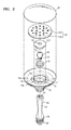
FIG. 2 is an exploded perspective view of an illumination device according to one or more embodiments; -
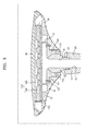
FIG. 3 is a cross-sectional view of an assembled structure of an illumination device such as the illumination device ofFIG. 1 , according to one or more embodiments; -
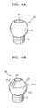
FIG. 4A is a perspective view of a conversion unit of an illumination device such as the illumination device, according to one or more embodiments; -
FIG. 4B is a perspective view of a modified example of a conversion unit of an illumination device according to one or more embodiments such as the conversion unit ofFIG. 4A ; -
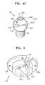
FIG. 4C is a perspective view of another modified example of a conversion unit of an illumination device according to one or more embodiments such as the conversion unit ofFIG. 4A ; -
FIG. 5 is a perspective view of a second assembly unit of the illumination device, according to one or more embodiments; -
FIG. 6A is a cross-sectional view of a coupling relationship between a conversion unit according to one or more embodiments such as the conversion unit ofFIG. 4B and a second assembly unit; -
FIG. 6B is a cross-sectional view of a coupling relationship between a conversion unit according to one or more embodiments such as the conversion unit ofFIG. 4C and a first and a second assembly unit; -
FIG. 7A is an exploded perspective view of a structure that includes an elastic member formed between an upper body and a first assembly unit in an illumination device according to one or more embodiments; -
FIG. 7B is a cross-sectional view of an assembled structure of an illumination device such as the illumination device ofFIG. 7A , according to one or more embodiments; -
FIG. 8A is an exploded perspective view of a structure that includes an elastic member formed between a second assembly unit and an illumination unit in an illumination device according to one or more embodiments; -
FIGS. 8B to 8D are cross-sectional views of various examples of elastic members included in an illumination device according to one or more embodiments; and -
FIG. 9 is a schematic drawing illustrating an example of changing light emission directions of an illumination device according to one or more embodiments. - Reference will now be made in detail to exemplary embodiments, examples of which are illustrated in the accompanying drawings. In the drawings, like reference numerals refer to like elements throughout and the size and thickness of each constituent element may be exaggerated for clarity of explanation.
- Referring to
FIG. 1 , the illumination device may include anupper body 10, on which a light-emitting unit that emits light may be mounted, and alower body 20 that may provide a power path for supplying power to the light-emitting unit and may be connected to another structure via asocket unit 50. Acover unit 40 may be formed on theupper body 10. Aconversion unit 30 may be formed between theupper body 10 and thelower body 20. Theconversion unit 30 may connect theupper body 10 and thelower body 20 together and may convert the direction of light emitted from the light-emitting unit. Thelower body 20 may be fixed on an external structure, and theupper body 10 may rotate or tilt to a desired direction with theconversion unit 30 as a center of rotation. - Referring to
FIG. 2 , theupper body 10 may include an assembly unit, for example, first andsecond assembly units unit 150 may be mounted on the assembly unit. The assembly unit may include first andsecond assembly units conversion unit 30 may be coupled between the first andsecond assembly units tap 32, which may be formed on theconversion unit 30, may protrude downwards in theupper body 10 through a throughhole 112 of thefirst assembly unit 110, and thus, may connect theupper body 10 to thelower body 20 by being coupled to acoupling unit 22 of thelower body 20. -
FIG. 3 is a cross-sectional view of an assembled structure of an illumination device such as the illumination device ofFIG. 1 , according to one or more embodiments. - Referring to
FIGS. 2 and3 , a step difference unit, for example, first, second, and thirdstep difference units upper body 10 to support and seat the first andsecond assembly units conversion unit 30, and the light-emittingunit 150. - Both edges that protrude on both sides of the
first assembly unit 110 may be positioned on theupper body 10 by being supported by the firststep difference unit 14a. A coupling means, for example, an adhesive may be optionally used between thefirst assembly unit 110 and theupper body 10. However, thefirst assembly unit 110 may be seated on theupper body 10 without using an additional coupling means. Theconversion unit 30 may be inserted into the throughhole 112 in thefirst assembly unit 110, and thetap 32 formed on theconversion unit 30 may protrude outside, that is, downwards in the throughhole 112 of thefirst assembly unit 110. Thetap 32 of theconversion unit 30 may be coupled to thecoupling unit 22 of thelower body 20, and spirals may be formed on surfaces of thetap 32 and thecoupling unit 22 to correspond to each other and readily couple to each other. - The
second assembly unit 120 may be located on thefirst assembly unit 110 and theconversion unit 30, edge portions that protrude on both sides of thesecond assembly unit 120 may be supported by the secondstep difference unit 14b. Afastener 121 may be used between thesecond assembly unit 120 and theupper body 10, for example, the both edges of thesecond assembly unit 120 and the secondstep difference unit 14b may be coupled by thefastener 121 having a spiral formed thereon. Also, optionally, the both edges of thesecond assembly unit 120 and the secondstep difference unit 14b may be coupled by using an adhesive. More than onefastener 121 may be used between thesecond assembly unit 120 and theupper body 10. When a binding force between thesecond assembly unit 120 and theupper body 10 is weak, thesecond assembly unit 120 and theupper body 10 may be separated from each other. In this case, theconversion unit 30 may be moved upwards. Therefore, a plurality offasteners 121 may be formed between the first andsecond assembly units upper body 10. The first andsecond assembly units conversion unit 30 and may rotate with theconversion unit 30 as a center of rotation. The light-emittingunit 150 may be located on the thirdstep difference unit 14c of theupper body 10. In order to dissipate heat generated from the light-emittingunit 150 to the outside, a contact area between the thirdstep difference unit 14c of theupper body 10 and the light-emittingunit 150 may be controlled or an additional contact area may further be formed. Anexternal surface 16 of theupper body 10 may have various shapes, for example, may have a wave shape. - In the case of the illumination device according to one or more embodiments, a light-emitting diode (LED), an incandescent lamp, a fluorescent lamp, or a halogen lamp may be used as a light source, and there are not specific limitations. In one or more embodiments, an LED may be used as a light source. The light-emitting
unit 150 may include anLED 160 mounted on asubstrate 140. For example, theLED 160 may be mounted on thesubstrate 140 after packaging at least one of an LED chip by a free-mold method using a lead frame, a mold frame, a fluorescent substance, or a transparent filler, for example. Also, theLED 160 may be mounted on thesubstrate 140 by mounting a plurality of LED chips by using a wire bonding method or a flip-chip bonding method, for example. Thesubstrate 140 may be a printed circuit board (PCB), for example, and may be a circuit substrate having a metal substrate or a metal core to possibly improve heat dissipation characteristics. The light-emittingunit 150 may receive power by being electrically connected to thesocket unit 50, for example, thesubstrate 140 and thesocket unit 50 may be connected via a wire. Throughholes upper body 10, thelower body 20, and theconversion unit 30 between the light-emittingunit 150 and thesocket unit 50 to provide a power path of a power supply element. Also, throughholes conversion unit 30 and providing a power path of a power supply element may be respectively formed in the first andsecond assembly units - The
cover unit 40 may be, for example, a dome-type transparent cover or the like, and may cover the light-emittingunit 150 by being coupled with theupper body 10. Thecover unit 40 may function as a lens and may be a diffusion cover that diffusively reflects and diffusively transmits light. Also, thecover unit 40 may function to keep the shape of the light-emittingunit 150 and also to protect the light-emittingunit 150. Thecover unit 40 may be formed of a transparent material that transmits light emitted from the light-emittingunit 150. For example, thecover unit 40 may be formed of a ceramic material, such as glass or alumina (Al2O3), a polycarbonate (PC) group resin material, or a polymethyl methacrylate (PMMA) group resin material, or the like. Also, in order to increase the thermal conductivity of thecover unit 40, a filler may be added to the glass, the PC group resin material, or the PMMA group resin material. Examples of the filler may be particles of carbon nanotube and graphene, and also, may be particles of titan oxide, zinc oxide, zirconium oxide, aluminum nitride, or aluminum oxide, or the like. Thecover unit 40 may be formed, for example, by using a molding method, such as an injection molding method and a blow molding method. - The
upper body 10 may include thefirst assembly unit 110, thesecond assembly unit 120, and the light-emittingunit 150 therein, and may be formed as a housing structure having step differences so that thefirst assembly unit 110, thesecond assembly unit 120, and the light-emittingunit 150 may be seated. The first, second, and thirdstep difference units units upper body 10 so that constituent elements may be mounted. Theupper body 10 may stably support the light-emittingunit 150, and may include a heat dissipation member to readily dissipate heat generated from theLEDs 160 to the outside. For example, a protrusion unit having various patterns may be formed on theexternal surface 16 of theupper body 10 to increase heat dissipation efficiency. Theupper body 10 may be formed of a material having high thermal conductivity. For example, theupper body 10 may be formed of a metal, such as aluminum or resin in which a thermal conductive filler may be dispersed. - The
lower body 20 may have a throughhole 24 therein to provide a power path for passing a cable for supplying power to the light-emittingunit 150. Thesocket unit 50 may be coupled to alower edge 26 of thelower body 20, and theconnection unit 22 may be formed on an upper inner edge of thelower body 20 so that thetap 32 of theconversion unit 30 may be coupled with theconnection unit 22. Materials for forming thelower body 20 are not specifically limited. For example, thelower body 20 may be formed of various types of synthetic resins and metals, and the like. Thelower body 20 may be coupled to an external structure directly or via thesocket unit 50. -
FIG. 4A is a perspective view of a conversion unit of an illumination device such as the illumination device, according to one or more embodiments. - Referring to
FIG. 4A , theconversion unit 30 may include a ball-shapedmain body unit 31 and thetap 32 formed by extending from themain body unit 31. Themain body unit 31 may not necessarily be a complete ball shape. Theconversion unit 30 may include the throughhole 34 to provide a power path for passing a power supply means that may supply power to the light-emittingunit 150. Themain body unit 31 of theconversion unit 30 may contact inner surfaces of the first andsecond assembly units main body unit 31 and the first andsecond assembly units main body unit 31 and the first andsecond assembly units unit 150 may be changed. Since theconversion unit 30 may have a contact position with the first andsecond assembly units conversion unit 30 may be formed of a material that does not easily wear. Theconversion unit 30 may be formed of, for example, a metal, plastic, or a synthetic resin, or the like. Theconversion unit 30 may be formed of, for example, a metal, such as aluminum, and a surface thereof may be optionally gloss treated. -
FIG. 4B is a perspective view of a modified example of a conversion unit of an illumination device according to one or more embodiments such as the conversion unit ofFIG. 4A . - Referring to
FIG. 4B , theconversion unit 30 may include a ball-shaped main body unit, for example, lower and uppermain bodies main body 310 may have a larger radius of curvature than that of the uppermain body 320. Theconversion unit 30 may not necessarily be a complete ball shape, and may be a combination of two types of domes having different radiuses of curvatures. Astep difference unit 314 may be formed on a region where the lowermain body 310 and the uppermain body 320 of theconversion unit 30 meet each other in a case where the lowermain body 310 has a greater width than that of the uppermain body 320. Aprotrusion unit 312 may be formed on the uppermain body 320, and theprotrusion unit 312 may be a portion formed by extending from the lowermain body 310 towards the uppermain body 320. A position conversion angle of thesecond assembly unit 120 that contacts theconversion unit 30 may be determined by theprotrusion unit 312 and thestep difference unit 314. -
FIG. 4C is a perspective view of another modified example of a conversion unit of an illumination device according to one or more embodiments such as the conversion unit ofFIG. 4A . - Referring to
FIG. 4C , theconversion unit 30 may include a ball-shapedmain body unit 33. Themain body unit 33 may include a firstmain body unit 33a, a secondmain body unit 33b, and alower surface unit 330 formed between the firstmain body unit 33a and the secondmain body unit 33b. Thelower surface unit 330 may be a region having a surface that is lower than surfaces of the firstmain body unit 33a and the secondmain body unit 33b. Thelower surface unit 330 may be a region having a smaller radius of curvature than that of the firstmain body unit 33a or the secondmain body unit 33b.Step difference units lower surface unit 330 and the firstmain body unit 33a and between thelower surface unit 330 and secondmain body unit 33b. Thelower surface unit 330 may include aprotrusion unit 322 that protrudes from thelower surface unit 330, and theprotrusion unit 322 may be a region formed by extending from the firstmain body unit 33a and the secondmain body unit 33b of both sides of thelower surface unit 330. A range of contact position of thesecond assembly unit 120 that contacts theconversion unit 30 may be controlled by thestep difference units lower surface unit 330 and theprotrusion unit 322. -
FIG. 5 is a perspective view of thesecond assembly unit 120 of the illumination device, according to one or more embodiments. - Referring to
FIG. 5 , both edge portions of thesecond assembly unit 120 may be supported by the secondstep difference unit 14b of theupper body 10. A surface of thesecond assembly unit 120 that contacts the secondstep difference unit 14b may be a firstlower surface 125a. At least onehole 126 for inserting the fastener 121 (refer toFIG. 3 ) may be formed in the firstlower surface 125a of thesecond assembly unit 120 so that thesecond assembly unit 120 may be coupled to the secondstep difference unit 14b of theupper body 10. A secondlower surface 125b of thesecond assembly unit 120 may contact or face an upper surface of thefirst assembly unit 110. - A third
lower surface 125c of thesecond assembly unit 120 may contact a portion of a region of themain body 31 of the conversion unit 30 (refer toFIG. 4A ) or the lowermain body 310 of the conversion unit 30 (refer toFIG. 4B ). The thirdlower surface 125c of thesecond assembly unit 120 may be formed to have a curvature so that the thirdlower surface 125c has a shape corresponding to themain body unit 31 of theconversion unit 30. Also, in the case of thefirst assembly unit 110, a region of thefirst assembly unit 110 that contacts theconversion unit 30 may be formed to have a curvature corresponding to the shape of the surface of theconversion unit 30. The first andsecond assembly units second assembly units second assembly units conversion unit 30. The first andsecond assembly units second assembly units conversion control unit 122 that protrudes from the thirdlower surface 125c may be formed on the third lower surface 125cof thesecond assembly unit 120. When theconversion unit 30 having a shape as depicted inFIGS. 4B or4C is used, theconversion control unit 122 may be formed to set a rotation range of thesecond assembly unit 120 that contacts theconversion unit 30. The position of theconversion control unit 122 may be controlled within the thirdlower surface 125c of thesecond assembly unit 120. Theconversion control unit 122 may contact or face the surface of theconversion unit 30. -
FIG. 6A is a cross-sectional view of a coupling relationship between a conversion unit according to one or more embodiments such as theconversion unit 30 ofFIG. 4B and an assembly unit according to one or more embodiments such as thesecond assembly unit 120 ofFIG. 5 . - Referring to
FIGS. 4B ,5 , and6A , some regions of the thirdlower surface 125c of thesecond assembly unit 120 may contact the lowermain body 310 of theconversion unit 30 and may be separate from a surface of the uppermain body 320. When an angle of thesecond assembly unit 120 is changed with theconversion unit 30 as a center, theconversion control unit 122 may move in a contact state or a separated state with a surface of the uppermain body 320 of theconversion unit 30. When theconversion control unit 122 meets thestep difference unit 314 of theconversion unit 30 or theprotrusion unit 312 of the uppermain body 320, theconversion control unit 122 may act as a stopper to stop the direction conversion, and set a limiting value of the direction conversion of thesecond assembly unit 120. - As depicted in
FIG. 6A , when thesecond assembly unit 120 rotates in an R1 direction, the rotation in the R1 direction may be stopped when theconversion control unit 122 of thesecond assembly unit 120 meets theprotrusion unit 312. Also, when thesecond assembly unit 120 rotates in an R2 direction, the rotation in the R2 direction may be stopped when theconversion control unit 122 meets thestep difference unit 314 of theconversion unit 30. If theconversion control unit 122 and theprotrusion unit 312 are not formed, thesecond assembly unit 120 may rotate at an angle of 3600 or greater in the R1 direction. However, if the need for rotating at such a large angle is low, theprotrusion unit 312 may be formed on theconversion unit 30. At least oneprotrusion unit 312 may be formed on the uppermain body 320 of theconversion unit 30. The amount of rotation in the R2 direction may be determined according to a gap or angle between thestep difference unit 314 of theconversion unit 30 to theconversion control unit 122 of thesecond assembly unit 120. If theconversion unit 30 is formed in the shape depicted inFIG. 4B , theupper body 10 may rotate in the R2 direction until a lower edge of theupper body 10 meets an upper edge of thelower body 20. -
FIG. 6B is a cross-sectional view of a coupling relationship between theconversion unit 30 ofFIG. 4C and the first andsecond assembly units - Referring to
FIGS. 4C, 5 , and6B , the first andsecond assembly units main body units second assembly unit 120, thesecond assembly unit 120 may contact the secondmain body unit 33b of thelower surface unit 330 while being separate from thelower surface unit 330. When an angle of thesecond assembly unit 120 is changed with theconversion unit 30 as a center, theconversion control unit 122a may be moved in a contact state or a non-contact sate with a surface of thelower surface unit 330. When thesecond assembly unit 120 rotates in the R1 direction, the rotation of theconversion control unit 122b may be stopped by contacting theprotrusion unit 322. Also, when thesecond assembly unit 120 rotates in the R2 direction, the rotation of theconversion control unit 122b may be stopped by contacting thestep difference units conversion control unit 122b may function as a stopper. -
FIG. 7A is an exploded perspective view of a structure that includes an elastic member formed between theupper body 10 and afirst assembly unit 110 in an illumination device according to one or more embodiments.FIG. 7B is a cross-sectional view of an assembled structure of an illumination device such as the illumination device ofFIG. 7A , according to one or more embodiments. - Referring to
FIGS. 7A and7B , when thefirst assembly unit 110 is seated on the firststep difference unit 14a in theupper body 10, a firstelastic member 210 may be inserted between thefirst assembly unit 110 and the firststep difference unit 14a. Theconversion unit 30 may perform a rotational motion when theconversion unit 30 is in contact with the first andsecond assembly units conversion unit 30 and the first andsecond assembly units conversion unit 30 and thefirst assembly unit 110 due to the friction between theconversion unit 30 and thefirst assembly unit 110 or between theconversion unit 30 and thesecond assembly unit 120. At this point, when theupper body 10 controls an angle by rotating with theconversion unit 30 as a center, tension that may maintain a desired angle of theupper body 10 may be insufficient. However, when the firstelastic member 210 is formed between thefirst assembly unit 110 and the firststep difference unit 14a, thefirst assembly unit 110 may have a restoration force corresponding to the pressing force of thefirst assembly unit 110 to the firstelastic member 210. Accordingly, since the firstelastic member 210 is formed between theconversion unit 30 and thefirst assembly unit 110, although there is friction between theconversion unit 30 and thefirst assembly unit 110, the occurrence of the gap may be prevented, and thus, a certain tension for maintaining a desired angle of theupper body 10 may be provided. - The first
elastic member 210 is formed between the firststep difference unit 14a of theupper body 10 and thefirst assembly unit 110, and thus, may have a circular shape. The firstelastic member 210 may have a size and a circumference suitable for seating on the firststep difference unit 14a and may have, for example, an O-ring shape. The firstelastic member 210 may be formed of various materials, for example, teflon, rubber, polymer, or silicon, but is not limited thereto. -
FIG. 8A is an exploded perspective view of a structure that includes an elastic member formed between asecond assembly unit 120 and an illumination unit in an illumination device according to one or more embodiments. - Referring to
FIG. 8A , thefirst assembly unit 110 may be seated on the firststep difference unit 14a in theupper body 10, theconversion unit 30 may be positioned on thefirst assembly unit 110, and thesecond assembly unit 120 may surround an upper edge of theconversion unit 30 and may be fixed on the secondstep difference unit 14b of theupper body 10. The light-emittingunit 150 may be positioned on thesecond assembly unit 120, and the light-emittingunit 150 may be seated on the thirdstep difference unit 14c of theupper body 10. A secondelastic member 220 may be inserted between thesecond assembly unit 120 and the light-emittingunit 150. - The second
elastic member 220 may prevent the occurrence of a minute gap between theconversion unit 30 and thefirst assembly unit 110 due to friction between theconversion unit 30 and thefirst assembly unit 110 or between theconversion unit 30 and thesecond assembly unit 120. When theupper body 10 controls an angle by rotating with theconversion unit 30 as a center, like the firstelastic member 210, the secondelastic member 220 may provide tension for maintaining a desired angle of theupper body 10. The secondelastic member 220 may have various shapes, such as adisc spring 230. Thedisc spring 230 may be formed, for example, of a metal, a polymer, or rubber, or the like. -
FIGS. 8B through 8D are cross-sectional views of various examples of elastic members included in an illumination device according to an exemplary embodiment. - Referring to
FIGS. 8A and8B , the secondelastic member 220 may be formed in a disc spring shape or a discus shape having a hole therein. An upper inner part of thedisc spring 230 may contact alower surface 140a of the light-emittingunit 150 and an outer lower part of thedisc spring 230 may contact an upper surface of thesecond assembly unit 120. On the other hand, an outer lower part of thedisc spring 230 may contact thelower surface 140a of the light-emittingunit 150 and a lower inner part of thedisc spring 230 may contact an upper surface of thesecond assembly unit 120; however, the shape thereof is not limited thereto. Since thedisc spring 230 is formed between thesecond assembly unit 120 and the light-emittingunit 150, tension between thesecond assembly unit 120 and the light-emittingunit 150 may be maintained. Thedisc spring 230 may be formed of, for example, a metal, a polymer, or rubber, or the like. - Referring to
FIGS. 8A and8C , the secondelastic member 220 may include afirst region 242 that contacts thesecond assembly unit 120 and asecond region 244 that contacts the light-emittingunit 150. Thesecond region 244 may protrude from thefirst region 242 to maintain tension between the secondelastic member 220 and the light-emittingunit 150. The secondelastic member 220 may respectively contact thesecond assembly unit 120 and the light-emittingunit 150 and may maintain tension between thesecond assembly unit 120 and the light-emittingunit 150. The secondelastic member 220 depicted inFIGS. 8B and8C has an O-ring shape, but the shape of the O-ring is not limited thereto. - Referring to
FIG. 8D , coil springs 250 may be formed between thesecond assembly unit 120 and the light-emittingunit 150. The secondelastic member 220 depicted inFIGS. 8B and8C has an O-ring shape. However, as depicted inFIG. 8D , the secondelastic member 220 may be formed in a coil spring shape having one or more coil springs 250. - In
FIG. 7A , the firstelastic member 210 may be formed between the firststep difference unit 14a and thefirst assembly unit 110 of theupper body 10, and inFIG. 8A , the secondelastic member 220 may be formed between the light-emittingunit 150 and thesecond assembly unit 120. In an illumination device according to one or more embodiments, one of the firstelastic member 210 and the secondelastic member 220 may be optionally formed, or both of the firstelastic member 210 and the secondelastic member 220 may be formed. -
FIG. 9 is a schematic drawing illustrating an example of changing light emission directions of the illumination device according to one or more embodiments. Since thesecond assembly unit 120 may be coupled to theupper body 10, the direction conversion of theconversion unit 30 by the rotation of thesecond assembly unit 120 may denote the angular conversion of theupper body 10 and the light-emittingunit 150. As a result, according to one or more embodiments, the light emission direction of light emitted from the light-emittingunit 150 may be converted to the R1 direction and the R2 direction. Also, as depicted inFIGS. 4B and4C , the conversion range of the emission direction of light emitted from the light-emittingunit 150 may be controlled by forming thestep difference units protrusion units conversion control unit 122 on thesecond assembly unit 120. - As described above, the illumination device according to one or more embodiments may include the
conversion unit 30 that may convert emission direction of light emitted from the light-emittingunit 150 therein, and the light emission direction may be controlled by forming thestep difference units conversion control unit 122. In the illumination device described above, the user may control the light emission direction to a desired direction by controlling theupper body 10 after fixing thelower body 20 on an external structure. Also, the illumination device may have tension for maintaining an illumination angle. - The illumination device according to one or more embodiments may include a means for converting light emission direction, and thus, the emission direction of light emitted from a light-emitting unit may be arbitrary controlled.
- Although a light emission direction conversion means according to one or more embodiments may not be installed on a structure on which the illumination will be mounted, the use of the illumination device according to the exemplary embodiment may control the emission direction of light emitted from a light-emitting unit.
- In the illumination device according to one or more embodiments, tension for maintaining an illumination angle may be provided by forming an elastic member on or under the
first assembly unit 110 and thesecond assembly unit 120. - While aspects of the present invention have been particularly shown and described with reference to differing embodiments thereof, it should be understood that these embodiments should be considered in a descriptive sense only and not for purposes of limitation. Descriptions of features or aspects within each embodiment should typically be considered as available for other similar features or aspects in the remaining embodiments. Suitable results may equally be achieved if the described techniques are performed in a different order and/or if components in a described system, architecture, device, or circuit are combined in a different manner and/or replaced or supplemented by other components or their equivalents.
- While one or more exemplary embodiments have been described with reference to the figures, it will be understood by those of ordinary skill in the art that various changes in form and details may be made therein without departing from the scope of the invention as defined by the following claims.
Claims (15)
- An illumination device, comprising:an upper body on which a light-emitting unit that emits light is mounted;a lower body that provides a power path to the light-emitting unit;a conversion unit coupled to the lower body; andan assembly unit that assembles the conversion unit to the upper body such that the conversion unit converts an emission direction of light emitted from the light-emitting unit of the upper body.
- The illumination device of claim 1, wherein the conversion unit comprises a ball-shaped main body unit, the assembly unit comprises a first assembly unit and a second assembly unit, and the first assembly unit and the second assembly unit each rotate in a state of surrounding and contacting the main body unit.
- The illumination device of claim 2, wherein the conversion unit comprises a tap formed by extending from the main body unit, and the tap is coupled to the lower body.
- The illumination device of claim 2, wherein the main body unit comprises a ball-shaped upper main body and a ball-shaped lower main body, the lower main body has a radius of curvature that is larger than a radius of curvature of the upper main body, and a step difference unit is formed between the lower main body and the upper main body.
- The illumination device of claim 4, wherein at least one conversion control unit that protrudes from the second assembly unit is formed on a lower surface of the second assembly unit, and the conversion control unit contacts or faces a surface of the upper main body.
- The illumination device of any one of claims 2 to 5, further comprising at least one protrusion unit formed on the upper main body.
- The illumination device of any one of claims 2 to 6, wherein the main body comprises a first main body unit, a second main body unit, and a step surface unit formed between the first main body unit and the second main body unit.
- The illumination device of claim 7, wherein at least one conversion control unit that protrudes from the second assembly unit is formed on a surface of the second assembly unit, and the conversion control unit contacts or faces the step surface unit.
- The illumination device of claim 8, wherein at least one protrusion unit is formed on a surface of the step surface unit.
- The illumination device of any one of claims 2 to 9, wherein edge portions that protrude on both sides of the first assembly unit are supported by a first step difference unit of the upper body, and edge portions that protrude on both sides of the second assembly unit are supported by a second step difference unit of the upper body.
- The illumination device of claim 10, wherein the second assembly unit and the second step difference unit of the upper body are coupled together by at least one assembling means.
- The illumination device of any one of the preceding claims, wherein the light-emitting unit is formed by mounting a plurality of diode chips on a substrate, and/or wherein a cover unit is formed on the upper body, and the cover unit is formed of glass, a ceramic material, a resin of polycarbonate (PC) group, or a resin of polymethyl methacrylate (PMMA), and/or wherein the upper body is formed as a housing structure having step differences so that the light-emitting unit and the first and second assembly units are seated thereon.
- The illumination device of any one of the preceding claims, wherein the lower body comprises a socket unit to supply power to the light-emitting unit from the socket unit.
- The illumination device of any one of the preceding claims when dependent on claim 2, wherein edge portions that protrude on both sides of the first assembly unit are supported by a step difference unit, and an elastic member is formed between the first assembly unit and the step difference unit, wherein the elastic member may have an O-ring shape.
- The illumination device of any one of claims 2 to 13 when dependent on claim 2, further comprising an elastic member formed between the second assembly unit and the light-emitting unit, wherein the elastic member may be formed as an O-ring or wherein the elastic member comprises at least one coil spring.
Applications Claiming Priority (2)
| Application Number | Priority Date | Filing Date | Title |
|---|---|---|---|
| KR20140037239 | 2014-03-28 | ||
| KR1020140128374A KR102352678B1 (en) | 2014-03-28 | 2014-09-25 | Illumination device that can be switched light emission direction |
Publications (2)
| Publication Number | Publication Date |
|---|---|
| EP2924332A1 true EP2924332A1 (en) | 2015-09-30 |
| EP2924332B1 EP2924332B1 (en) | 2018-05-02 |
Family
ID=53039677
Family Applications (1)
| Application Number | Title | Priority Date | Filing Date |
|---|---|---|---|
| EP15160859.3A Not-in-force EP2924332B1 (en) | 2014-03-28 | 2015-03-25 | Illumination device that switches light emission direction |
Country Status (2)
| Country | Link |
|---|---|
| US (1) | US9574753B2 (en) |
| EP (1) | EP2924332B1 (en) |
Cited By (3)
| Publication number | Priority date | Publication date | Assignee | Title |
|---|---|---|---|---|
| CN106609922A (en) * | 2015-10-22 | 2017-05-03 | 宏力照明集团有限公司 | Universal LED lamp |
| CN109357209A (en) * | 2018-09-28 | 2019-02-19 | 广东岩羊照明有限公司 | A kind of new structure Adjustable head lamp |
| US10697619B2 (en) | 2016-09-08 | 2020-06-30 | Kilt Planning Office Inc. | Surface light emission system, lighting system, and lighting space reproduction method |
Citations (10)
| Publication number | Priority date | Publication date | Assignee | Title |
|---|---|---|---|---|
| US4258414A (en) * | 1979-08-01 | 1981-03-24 | Plymouth Products Incorporated | Universal trouble light |
| GB2229765A (en) * | 1989-03-24 | 1990-10-03 | Musashi Seimitsu Kogyo Kk | Ball construction of a ball-and-socket joint and method of manufacture |
| US20070065227A1 (en) * | 2005-09-20 | 2007-03-22 | Sellers Roger G | Cone adaptor for ball joint studs, tie rods, sway bar links and the like |
| US7695170B1 (en) * | 2007-06-27 | 2010-04-13 | Taymac Corporation | Outdoor swivel head spotlight |
| US20110019438A1 (en) * | 2009-07-24 | 2011-01-27 | Cal-Comp Electronics & Communications Company Limited | Light emitting diode lamp |
| WO2011132159A1 (en) * | 2010-04-23 | 2011-10-27 | Koninklijke Philips Electronics N.V. | Led-based lighting unit |
| EP2442020A2 (en) * | 2010-10-12 | 2012-04-18 | Halemeier GmbH & Co. KG | Light with pivotable flat light unit |
| EP2570723A1 (en) * | 2011-09-15 | 2013-03-20 | Kaipo Chen | Bulb with Sensing Function and Camera |
| US20130182437A1 (en) * | 2010-09-16 | 2013-07-18 | Osram Gmbh | Illumination device having a heat sink and method for directing a light bundle emitted by an illumination device |
| KR20130097100A (en) * | 2012-02-23 | 2013-09-02 | 주식회사 케이엠더블유 | Random light distribution lamp |
Family Cites Families (6)
| Publication number | Priority date | Publication date | Assignee | Title |
|---|---|---|---|---|
| KR20080005009U (en) | 2007-04-25 | 2008-10-29 | 주식회사 대진디엠피 | Housing for buried Light using by LED |
| US20090323339A1 (en) * | 2008-06-04 | 2009-12-31 | The L.D. Kichler Co. | Positionable lighting assemblies |
| US8109660B2 (en) * | 2008-08-07 | 2012-02-07 | Relume Technologies, Inc. | Globe deployable LED light assembly |
| KR101170257B1 (en) | 2010-09-28 | 2012-07-31 | 영남대학교 산학협력단 | Illuminator having LED module position variable |
| US8602612B2 (en) * | 2011-05-12 | 2013-12-10 | Peter Stathis | Electrically conductive ball joints and lighting fixtures using the joints |
| KR101425516B1 (en) | 2012-08-29 | 2014-07-31 | 쓰리아이전기 주식회사 | LED lamp for streetlight |
-
2015
- 2015-03-25 EP EP15160859.3A patent/EP2924332B1/en not_active Not-in-force
- 2015-03-30 US US14/672,603 patent/US9574753B2/en active Active
Patent Citations (10)
| Publication number | Priority date | Publication date | Assignee | Title |
|---|---|---|---|---|
| US4258414A (en) * | 1979-08-01 | 1981-03-24 | Plymouth Products Incorporated | Universal trouble light |
| GB2229765A (en) * | 1989-03-24 | 1990-10-03 | Musashi Seimitsu Kogyo Kk | Ball construction of a ball-and-socket joint and method of manufacture |
| US20070065227A1 (en) * | 2005-09-20 | 2007-03-22 | Sellers Roger G | Cone adaptor for ball joint studs, tie rods, sway bar links and the like |
| US7695170B1 (en) * | 2007-06-27 | 2010-04-13 | Taymac Corporation | Outdoor swivel head spotlight |
| US20110019438A1 (en) * | 2009-07-24 | 2011-01-27 | Cal-Comp Electronics & Communications Company Limited | Light emitting diode lamp |
| WO2011132159A1 (en) * | 2010-04-23 | 2011-10-27 | Koninklijke Philips Electronics N.V. | Led-based lighting unit |
| US20130182437A1 (en) * | 2010-09-16 | 2013-07-18 | Osram Gmbh | Illumination device having a heat sink and method for directing a light bundle emitted by an illumination device |
| EP2442020A2 (en) * | 2010-10-12 | 2012-04-18 | Halemeier GmbH & Co. KG | Light with pivotable flat light unit |
| EP2570723A1 (en) * | 2011-09-15 | 2013-03-20 | Kaipo Chen | Bulb with Sensing Function and Camera |
| KR20130097100A (en) * | 2012-02-23 | 2013-09-02 | 주식회사 케이엠더블유 | Random light distribution lamp |
Cited By (3)
| Publication number | Priority date | Publication date | Assignee | Title |
|---|---|---|---|---|
| CN106609922A (en) * | 2015-10-22 | 2017-05-03 | 宏力照明集团有限公司 | Universal LED lamp |
| US10697619B2 (en) | 2016-09-08 | 2020-06-30 | Kilt Planning Office Inc. | Surface light emission system, lighting system, and lighting space reproduction method |
| CN109357209A (en) * | 2018-09-28 | 2019-02-19 | 广东岩羊照明有限公司 | A kind of new structure Adjustable head lamp |
Also Published As
| Publication number | Publication date |
|---|---|
| US20150276183A1 (en) | 2015-10-01 |
| US9574753B2 (en) | 2017-02-21 |
| EP2924332B1 (en) | 2018-05-02 |
Similar Documents
| Publication | Publication Date | Title |
|---|---|---|
| JP5806767B2 (en) | Lighting device | |
| US8403522B2 (en) | LED lamp | |
| TWI579500B (en) | Lighting module | |
| US9964257B2 (en) | Illumination device for preventing a removal of a module substrate and suppressing generation of a crack in the module substrate | |
| US20130027938A1 (en) | Bulb-type led lamp | |
| US9651223B2 (en) | Light-emitting apparatus with fastening of optical component to pedestal through light-emitting substrate through-hole, illumination light source having the same, and lighting apparatus having the same | |
| US20130088880A1 (en) | Led lighting device | |
| US9115854B2 (en) | Light emitting diode bulb | |
| US9551478B2 (en) | Lighting device | |
| EP2924332B1 (en) | Illumination device that switches light emission direction | |
| KR102352678B1 (en) | Illumination device that can be switched light emission direction | |
| TW201200789A (en) | Push-pull SSL module and socket | |
| EP2748529B1 (en) | Solid state lighting module with improved heat spreader | |
| JP5560319B2 (en) | Light emitting diode element | |
| US20090078950A1 (en) | Package structure with replaceable element for light emitting diode | |
| US20180299112A1 (en) | Led light source | |
| TWI501428B (en) | Light emitting diode package structure | |
| JP2012227057A (en) | Lamp unit and lamp socket | |
| JP7186368B2 (en) | lighting equipment | |
| KR101800376B1 (en) | Lighting device | |
| JP2018078004A (en) | Light fitting | |
| KR101729010B1 (en) | Lighting device | |
| KR101729011B1 (en) | Optic cover and lighting device having same | |
| KR20150081661A (en) | Driver on board type led industry light with alternating current led | |
| KR102236183B1 (en) | Lighting device |
Legal Events
| Date | Code | Title | Description |
|---|---|---|---|
| PUAI | Public reference made under article 153(3) epc to a published international application that has entered the european phase |
Free format text: ORIGINAL CODE: 0009012 |
|
| 17P | Request for examination filed |
Effective date: 20150325 |
|
| AK | Designated contracting states |
Kind code of ref document: A1 Designated state(s): AL AT BE BG CH CY CZ DE DK EE ES FI FR GB GR HR HU IE IS IT LI LT LU LV MC MK MT NL NO PL PT RO RS SE SI SK SM TR |
|
| AX | Request for extension of the european patent |
Extension state: BA ME |
|
| STAA | Information on the status of an ep patent application or granted ep patent |
Free format text: STATUS: EXAMINATION IS IN PROGRESS |
|
| 17Q | First examination report despatched |
Effective date: 20170310 |
|
| REG | Reference to a national code |
Ref country code: DE Ref legal event code: R079 Ref document number: 602015010576 Country of ref document: DE Free format text: PREVIOUS MAIN CLASS: F21K0099000000 Ipc: F21V0014020000 |
|
| RIC1 | Information provided on ipc code assigned before grant |
Ipc: F21Y 115/10 20160101ALN20170830BHEP Ipc: F21K 9/65 20160101ALI20170830BHEP Ipc: F21V 14/02 20060101AFI20170830BHEP Ipc: F21V 21/29 20060101ALI20170830BHEP Ipc: F21K 9/23 20160101ALI20170830BHEP |
|
| GRAP | Despatch of communication of intention to grant a patent |
Free format text: ORIGINAL CODE: EPIDOSNIGR1 |
|
| STAA | Information on the status of an ep patent application or granted ep patent |
Free format text: STATUS: GRANT OF PATENT IS INTENDED |
|
| INTG | Intention to grant announced |
Effective date: 20171009 |
|
| GRAS | Grant fee paid |
Free format text: ORIGINAL CODE: EPIDOSNIGR3 |
|
| GRAA | (expected) grant |
Free format text: ORIGINAL CODE: 0009210 |
|
| STAA | Information on the status of an ep patent application or granted ep patent |
Free format text: STATUS: THE PATENT HAS BEEN GRANTED |
|
| AK | Designated contracting states |
Kind code of ref document: B1 Designated state(s): AL AT BE BG CH CY CZ DE DK EE ES FI FR GB GR HR HU IE IS IT LI LT LU LV MC MK MT NL NO PL PT RO RS SE SI SK SM TR |
|
| REG | Reference to a national code |
Ref country code: GB Ref legal event code: FG4D |
|
| REG | Reference to a national code |
Ref country code: CH Ref legal event code: EP Ref country code: AT Ref legal event code: REF Ref document number: 995656 Country of ref document: AT Kind code of ref document: T Effective date: 20180515 |
|
| REG | Reference to a national code |
Ref country code: DE Ref legal event code: R096 Ref document number: 602015010576 Country of ref document: DE Ref country code: IE Ref legal event code: FG4D |
|
| REG | Reference to a national code |
Ref country code: NL Ref legal event code: MP Effective date: 20180502 |
|
| REG | Reference to a national code |
Ref country code: LT Ref legal event code: MG4D |
|
| PG25 | Lapsed in a contracting state [announced via postgrant information from national office to epo] |
Ref country code: ES Free format text: LAPSE BECAUSE OF FAILURE TO SUBMIT A TRANSLATION OF THE DESCRIPTION OR TO PAY THE FEE WITHIN THE PRESCRIBED TIME-LIMIT Effective date: 20180502 Ref country code: SE Free format text: LAPSE BECAUSE OF FAILURE TO SUBMIT A TRANSLATION OF THE DESCRIPTION OR TO PAY THE FEE WITHIN THE PRESCRIBED TIME-LIMIT Effective date: 20180502 Ref country code: FI Free format text: LAPSE BECAUSE OF FAILURE TO SUBMIT A TRANSLATION OF THE DESCRIPTION OR TO PAY THE FEE WITHIN THE PRESCRIBED TIME-LIMIT Effective date: 20180502 Ref country code: NO Free format text: LAPSE BECAUSE OF FAILURE TO SUBMIT A TRANSLATION OF THE DESCRIPTION OR TO PAY THE FEE WITHIN THE PRESCRIBED TIME-LIMIT Effective date: 20180802 Ref country code: BG Free format text: LAPSE BECAUSE OF FAILURE TO SUBMIT A TRANSLATION OF THE DESCRIPTION OR TO PAY THE FEE WITHIN THE PRESCRIBED TIME-LIMIT Effective date: 20180802 Ref country code: LT Free format text: LAPSE BECAUSE OF FAILURE TO SUBMIT A TRANSLATION OF THE DESCRIPTION OR TO PAY THE FEE WITHIN THE PRESCRIBED TIME-LIMIT Effective date: 20180502 |
|
| PG25 | Lapsed in a contracting state [announced via postgrant information from national office to epo] |
Ref country code: GR Free format text: LAPSE BECAUSE OF FAILURE TO SUBMIT A TRANSLATION OF THE DESCRIPTION OR TO PAY THE FEE WITHIN THE PRESCRIBED TIME-LIMIT Effective date: 20180803 Ref country code: NL Free format text: LAPSE BECAUSE OF FAILURE TO SUBMIT A TRANSLATION OF THE DESCRIPTION OR TO PAY THE FEE WITHIN THE PRESCRIBED TIME-LIMIT Effective date: 20180502 Ref country code: LV Free format text: LAPSE BECAUSE OF FAILURE TO SUBMIT A TRANSLATION OF THE DESCRIPTION OR TO PAY THE FEE WITHIN THE PRESCRIBED TIME-LIMIT Effective date: 20180502 Ref country code: HR Free format text: LAPSE BECAUSE OF FAILURE TO SUBMIT A TRANSLATION OF THE DESCRIPTION OR TO PAY THE FEE WITHIN THE PRESCRIBED TIME-LIMIT Effective date: 20180502 Ref country code: RS Free format text: LAPSE BECAUSE OF FAILURE TO SUBMIT A TRANSLATION OF THE DESCRIPTION OR TO PAY THE FEE WITHIN THE PRESCRIBED TIME-LIMIT Effective date: 20180502 |
|
| REG | Reference to a national code |
Ref country code: AT Ref legal event code: MK05 Ref document number: 995656 Country of ref document: AT Kind code of ref document: T Effective date: 20180502 |
|
| PG25 | Lapsed in a contracting state [announced via postgrant information from national office to epo] |
Ref country code: RO Free format text: LAPSE BECAUSE OF FAILURE TO SUBMIT A TRANSLATION OF THE DESCRIPTION OR TO PAY THE FEE WITHIN THE PRESCRIBED TIME-LIMIT Effective date: 20180502 Ref country code: CZ Free format text: LAPSE BECAUSE OF FAILURE TO SUBMIT A TRANSLATION OF THE DESCRIPTION OR TO PAY THE FEE WITHIN THE PRESCRIBED TIME-LIMIT Effective date: 20180502 Ref country code: EE Free format text: LAPSE BECAUSE OF FAILURE TO SUBMIT A TRANSLATION OF THE DESCRIPTION OR TO PAY THE FEE WITHIN THE PRESCRIBED TIME-LIMIT Effective date: 20180502 Ref country code: AT Free format text: LAPSE BECAUSE OF FAILURE TO SUBMIT A TRANSLATION OF THE DESCRIPTION OR TO PAY THE FEE WITHIN THE PRESCRIBED TIME-LIMIT Effective date: 20180502 Ref country code: PL Free format text: LAPSE BECAUSE OF FAILURE TO SUBMIT A TRANSLATION OF THE DESCRIPTION OR TO PAY THE FEE WITHIN THE PRESCRIBED TIME-LIMIT Effective date: 20180502 Ref country code: DK Free format text: LAPSE BECAUSE OF FAILURE TO SUBMIT A TRANSLATION OF THE DESCRIPTION OR TO PAY THE FEE WITHIN THE PRESCRIBED TIME-LIMIT Effective date: 20180502 Ref country code: SK Free format text: LAPSE BECAUSE OF FAILURE TO SUBMIT A TRANSLATION OF THE DESCRIPTION OR TO PAY THE FEE WITHIN THE PRESCRIBED TIME-LIMIT Effective date: 20180502 |
|
| REG | Reference to a national code |
Ref country code: DE Ref legal event code: R097 Ref document number: 602015010576 Country of ref document: DE |
|
| PG25 | Lapsed in a contracting state [announced via postgrant information from national office to epo] |
Ref country code: IT Free format text: LAPSE BECAUSE OF FAILURE TO SUBMIT A TRANSLATION OF THE DESCRIPTION OR TO PAY THE FEE WITHIN THE PRESCRIBED TIME-LIMIT Effective date: 20180502 Ref country code: SM Free format text: LAPSE BECAUSE OF FAILURE TO SUBMIT A TRANSLATION OF THE DESCRIPTION OR TO PAY THE FEE WITHIN THE PRESCRIBED TIME-LIMIT Effective date: 20180502 |
|
| PLBE | No opposition filed within time limit |
Free format text: ORIGINAL CODE: 0009261 |
|
| STAA | Information on the status of an ep patent application or granted ep patent |
Free format text: STATUS: NO OPPOSITION FILED WITHIN TIME LIMIT |
|
| 26N | No opposition filed |
Effective date: 20190205 |
|
| PG25 | Lapsed in a contracting state [announced via postgrant information from national office to epo] |
Ref country code: SI Free format text: LAPSE BECAUSE OF FAILURE TO SUBMIT A TRANSLATION OF THE DESCRIPTION OR TO PAY THE FEE WITHIN THE PRESCRIBED TIME-LIMIT Effective date: 20180502 |
|
| REG | Reference to a national code |
Ref country code: DE Ref legal event code: R119 Ref document number: 602015010576 Country of ref document: DE |
|
| PG25 | Lapsed in a contracting state [announced via postgrant information from national office to epo] |
Ref country code: MC Free format text: LAPSE BECAUSE OF FAILURE TO SUBMIT A TRANSLATION OF THE DESCRIPTION OR TO PAY THE FEE WITHIN THE PRESCRIBED TIME-LIMIT Effective date: 20180502 |
|
| REG | Reference to a national code |
Ref country code: CH Ref legal event code: PL |
|
| PG25 | Lapsed in a contracting state [announced via postgrant information from national office to epo] |
Ref country code: LU Free format text: LAPSE BECAUSE OF NON-PAYMENT OF DUE FEES Effective date: 20190325 Ref country code: AL Free format text: LAPSE BECAUSE OF FAILURE TO SUBMIT A TRANSLATION OF THE DESCRIPTION OR TO PAY THE FEE WITHIN THE PRESCRIBED TIME-LIMIT Effective date: 20180502 |
|
| REG | Reference to a national code |
Ref country code: BE Ref legal event code: MM Effective date: 20190331 |
|
| PG25 | Lapsed in a contracting state [announced via postgrant information from national office to epo] |
Ref country code: DE Free format text: LAPSE BECAUSE OF NON-PAYMENT OF DUE FEES Effective date: 20191001 Ref country code: IE Free format text: LAPSE BECAUSE OF NON-PAYMENT OF DUE FEES Effective date: 20190325 Ref country code: LI Free format text: LAPSE BECAUSE OF NON-PAYMENT OF DUE FEES Effective date: 20190331 Ref country code: CH Free format text: LAPSE BECAUSE OF NON-PAYMENT OF DUE FEES Effective date: 20190331 |
|
| PG25 | Lapsed in a contracting state [announced via postgrant information from national office to epo] |
Ref country code: BE Free format text: LAPSE BECAUSE OF NON-PAYMENT OF DUE FEES Effective date: 20190331 |
|
| PG25 | Lapsed in a contracting state [announced via postgrant information from national office to epo] |
Ref country code: TR Free format text: LAPSE BECAUSE OF FAILURE TO SUBMIT A TRANSLATION OF THE DESCRIPTION OR TO PAY THE FEE WITHIN THE PRESCRIBED TIME-LIMIT Effective date: 20180502 |
|
| PG25 | Lapsed in a contracting state [announced via postgrant information from national office to epo] |
Ref country code: PT Free format text: LAPSE BECAUSE OF FAILURE TO SUBMIT A TRANSLATION OF THE DESCRIPTION OR TO PAY THE FEE WITHIN THE PRESCRIBED TIME-LIMIT Effective date: 20180903 Ref country code: MT Free format text: LAPSE BECAUSE OF NON-PAYMENT OF DUE FEES Effective date: 20190325 |
|
| PGFP | Annual fee paid to national office [announced via postgrant information from national office to epo] |
Ref country code: FR Payment date: 20200221 Year of fee payment: 6 |
|
| PG25 | Lapsed in a contracting state [announced via postgrant information from national office to epo] |
Ref country code: CY Free format text: LAPSE BECAUSE OF FAILURE TO SUBMIT A TRANSLATION OF THE DESCRIPTION OR TO PAY THE FEE WITHIN THE PRESCRIBED TIME-LIMIT Effective date: 20180502 |
|
| PGFP | Annual fee paid to national office [announced via postgrant information from national office to epo] |
Ref country code: GB Payment date: 20210216 Year of fee payment: 7 |
|
| PG25 | Lapsed in a contracting state [announced via postgrant information from national office to epo] |
Ref country code: IS Free format text: LAPSE BECAUSE OF FAILURE TO SUBMIT A TRANSLATION OF THE DESCRIPTION OR TO PAY THE FEE WITHIN THE PRESCRIBED TIME-LIMIT Effective date: 20180902 |
|
| PG25 | Lapsed in a contracting state [announced via postgrant information from national office to epo] |
Ref country code: HU Free format text: LAPSE BECAUSE OF FAILURE TO SUBMIT A TRANSLATION OF THE DESCRIPTION OR TO PAY THE FEE WITHIN THE PRESCRIBED TIME-LIMIT; INVALID AB INITIO Effective date: 20150325 |
|
| PG25 | Lapsed in a contracting state [announced via postgrant information from national office to epo] |
Ref country code: FR Free format text: LAPSE BECAUSE OF NON-PAYMENT OF DUE FEES Effective date: 20210331 |
|
| PG25 | Lapsed in a contracting state [announced via postgrant information from national office to epo] |
Ref country code: MK Free format text: LAPSE BECAUSE OF FAILURE TO SUBMIT A TRANSLATION OF THE DESCRIPTION OR TO PAY THE FEE WITHIN THE PRESCRIBED TIME-LIMIT Effective date: 20180502 |
|
| GBPC | Gb: european patent ceased through non-payment of renewal fee |
Effective date: 20220325 |
|
| PG25 | Lapsed in a contracting state [announced via postgrant information from national office to epo] |
Ref country code: GB Free format text: LAPSE BECAUSE OF NON-PAYMENT OF DUE FEES Effective date: 20220325 |