EP2924328A1 - Line-shaped assembly - Google Patents
Line-shaped assembly Download PDFInfo
- Publication number
- EP2924328A1 EP2924328A1 EP13868875.9A EP13868875A EP2924328A1 EP 2924328 A1 EP2924328 A1 EP 2924328A1 EP 13868875 A EP13868875 A EP 13868875A EP 2924328 A1 EP2924328 A1 EP 2924328A1
- Authority
- EP
- European Patent Office
- Prior art keywords
- heat source
- line
- protective member
- shaped assembly
- body portion
- Prior art date
- Legal status (The legal status is an assumption and is not a legal conclusion. Google has not performed a legal analysis and makes no representation as to the accuracy of the status listed.)
- Withdrawn
Links
- 230000001681 protective effect Effects 0.000 claims abstract description 96
- 239000011347 resin Substances 0.000 claims abstract description 16
- 229920005989 resin Polymers 0.000 claims abstract description 16
- 229910052751 metal Inorganic materials 0.000 claims description 44
- 239000002184 metal Substances 0.000 claims description 44
- 239000004020 conductor Substances 0.000 description 21
- 239000002826 coolant Substances 0.000 description 15
- 239000012212 insulator Substances 0.000 description 8
- 239000007788 liquid Substances 0.000 description 8
- 239000007787 solid Substances 0.000 description 6
- 230000013011 mating Effects 0.000 description 5
- 239000000463 material Substances 0.000 description 4
- 230000000052 comparative effect Effects 0.000 description 3
- 239000011888 foil Substances 0.000 description 3
- 230000004048 modification Effects 0.000 description 3
- 238000012986 modification Methods 0.000 description 3
- 229910000838 Al alloy Inorganic materials 0.000 description 2
- 238000001816 cooling Methods 0.000 description 2
- 230000005611 electricity Effects 0.000 description 2
- 238000001125 extrusion Methods 0.000 description 2
- 230000017525 heat dissipation Effects 0.000 description 2
- 230000020169 heat generation Effects 0.000 description 2
- 238000009413 insulation Methods 0.000 description 2
- RYGMFSIKBFXOCR-UHFFFAOYSA-N Copper Chemical compound [Cu] RYGMFSIKBFXOCR-UHFFFAOYSA-N 0.000 description 1
- 229910000881 Cu alloy Inorganic materials 0.000 description 1
- 239000000956 alloy Substances 0.000 description 1
- 229910052782 aluminium Inorganic materials 0.000 description 1
- XAGFODPZIPBFFR-UHFFFAOYSA-N aluminium Chemical compound [Al] XAGFODPZIPBFFR-UHFFFAOYSA-N 0.000 description 1
- 229910052802 copper Inorganic materials 0.000 description 1
- 239000010949 copper Substances 0.000 description 1
- 239000007789 gas Substances 0.000 description 1
- 230000010354 integration Effects 0.000 description 1
- 239000007769 metal material Substances 0.000 description 1
- 239000000126 substance Substances 0.000 description 1
- XLYOFNOQVPJJNP-UHFFFAOYSA-N water Substances O XLYOFNOQVPJJNP-UHFFFAOYSA-N 0.000 description 1
- 238000003466 welding Methods 0.000 description 1
Images


Classifications
-
- H—ELECTRICITY
- H01—ELECTRIC ELEMENTS
- H01B—CABLES; CONDUCTORS; INSULATORS; SELECTION OF MATERIALS FOR THEIR CONDUCTIVE, INSULATING OR DIELECTRIC PROPERTIES
- H01B7/00—Insulated conductors or cables characterised by their form
- H01B7/17—Protection against damage caused by external factors, e.g. sheaths or armouring
- H01B7/29—Protection against damage caused by extremes of temperature or by flame
-
- B—PERFORMING OPERATIONS; TRANSPORTING
- B32—LAYERED PRODUCTS
- B32B—LAYERED PRODUCTS, i.e. PRODUCTS BUILT-UP OF STRATA OF FLAT OR NON-FLAT, e.g. CELLULAR OR HONEYCOMB, FORM
- B32B1/00—Layered products having a non-planar shape
- B32B1/08—Tubular products
-
- B—PERFORMING OPERATIONS; TRANSPORTING
- B32—LAYERED PRODUCTS
- B32B—LAYERED PRODUCTS, i.e. PRODUCTS BUILT-UP OF STRATA OF FLAT OR NON-FLAT, e.g. CELLULAR OR HONEYCOMB, FORM
- B32B15/00—Layered products comprising a layer of metal
- B32B15/04—Layered products comprising a layer of metal comprising metal as the main or only constituent of a layer, which is next to another layer of the same or of a different material
- B32B15/08—Layered products comprising a layer of metal comprising metal as the main or only constituent of a layer, which is next to another layer of the same or of a different material of synthetic resin
-
- B—PERFORMING OPERATIONS; TRANSPORTING
- B32—LAYERED PRODUCTS
- B32B—LAYERED PRODUCTS, i.e. PRODUCTS BUILT-UP OF STRATA OF FLAT OR NON-FLAT, e.g. CELLULAR OR HONEYCOMB, FORM
- B32B15/00—Layered products comprising a layer of metal
- B32B15/20—Layered products comprising a layer of metal comprising aluminium or copper
-
- B—PERFORMING OPERATIONS; TRANSPORTING
- B32—LAYERED PRODUCTS
- B32B—LAYERED PRODUCTS, i.e. PRODUCTS BUILT-UP OF STRATA OF FLAT OR NON-FLAT, e.g. CELLULAR OR HONEYCOMB, FORM
- B32B3/00—Layered products comprising a layer with external or internal discontinuities or unevennesses, or a layer of non-planar shape; Layered products comprising a layer having particular features of form
- B32B3/26—Layered products comprising a layer with external or internal discontinuities or unevennesses, or a layer of non-planar shape; Layered products comprising a layer having particular features of form characterised by a particular shape of the outline of the cross-section of a continuous layer; characterised by a layer with cavities or internal voids ; characterised by an apertured layer
- B32B3/28—Layered products comprising a layer with external or internal discontinuities or unevennesses, or a layer of non-planar shape; Layered products comprising a layer having particular features of form characterised by a particular shape of the outline of the cross-section of a continuous layer; characterised by a layer with cavities or internal voids ; characterised by an apertured layer characterised by a layer comprising a deformed thin sheet, i.e. the layer having its entire thickness deformed out of the plane, e.g. corrugated, crumpled
-
- B—PERFORMING OPERATIONS; TRANSPORTING
- B60—VEHICLES IN GENERAL
- B60R—VEHICLES, VEHICLE FITTINGS, OR VEHICLE PARTS, NOT OTHERWISE PROVIDED FOR
- B60R16/00—Electric or fluid circuits specially adapted for vehicles and not otherwise provided for; Arrangement of elements of electric or fluid circuits specially adapted for vehicles and not otherwise provided for
- B60R16/02—Electric or fluid circuits specially adapted for vehicles and not otherwise provided for; Arrangement of elements of electric or fluid circuits specially adapted for vehicles and not otherwise provided for electric constitutive elements
- B60R16/0207—Wire harnesses
- B60R16/0215—Protecting, fastening and routing means therefor
-
- F—MECHANICAL ENGINEERING; LIGHTING; HEATING; WEAPONS; BLASTING
- F16—ENGINEERING ELEMENTS AND UNITS; GENERAL MEASURES FOR PRODUCING AND MAINTAINING EFFECTIVE FUNCTIONING OF MACHINES OR INSTALLATIONS; THERMAL INSULATION IN GENERAL
- F16L—PIPES; JOINTS OR FITTINGS FOR PIPES; SUPPORTS FOR PIPES, CABLES OR PROTECTIVE TUBING; MEANS FOR THERMAL INSULATION IN GENERAL
- F16L11/00—Hoses, i.e. flexible pipes
- F16L11/04—Hoses, i.e. flexible pipes made of rubber or flexible plastics
- F16L11/12—Hoses, i.e. flexible pipes made of rubber or flexible plastics with arrangements for particular purposes, e.g. specially profiled, with protecting layer, heated, electrically conducting
-
- F—MECHANICAL ENGINEERING; LIGHTING; HEATING; WEAPONS; BLASTING
- F16—ENGINEERING ELEMENTS AND UNITS; GENERAL MEASURES FOR PRODUCING AND MAINTAINING EFFECTIVE FUNCTIONING OF MACHINES OR INSTALLATIONS; THERMAL INSULATION IN GENERAL
- F16L—PIPES; JOINTS OR FITTINGS FOR PIPES; SUPPORTS FOR PIPES, CABLES OR PROTECTIVE TUBING; MEANS FOR THERMAL INSULATION IN GENERAL
- F16L11/00—Hoses, i.e. flexible pipes
- F16L11/20—Double-walled hoses, i.e. two concentric hoses
-
- F—MECHANICAL ENGINEERING; LIGHTING; HEATING; WEAPONS; BLASTING
- F16—ENGINEERING ELEMENTS AND UNITS; GENERAL MEASURES FOR PRODUCING AND MAINTAINING EFFECTIVE FUNCTIONING OF MACHINES OR INSTALLATIONS; THERMAL INSULATION IN GENERAL
- F16L—PIPES; JOINTS OR FITTINGS FOR PIPES; SUPPORTS FOR PIPES, CABLES OR PROTECTIVE TUBING; MEANS FOR THERMAL INSULATION IN GENERAL
- F16L57/00—Protection of pipes or objects of similar shape against external or internal damage or wear
-
- F—MECHANICAL ENGINEERING; LIGHTING; HEATING; WEAPONS; BLASTING
- F16—ENGINEERING ELEMENTS AND UNITS; GENERAL MEASURES FOR PRODUCING AND MAINTAINING EFFECTIVE FUNCTIONING OF MACHINES OR INSTALLATIONS; THERMAL INSULATION IN GENERAL
- F16L—PIPES; JOINTS OR FITTINGS FOR PIPES; SUPPORTS FOR PIPES, CABLES OR PROTECTIVE TUBING; MEANS FOR THERMAL INSULATION IN GENERAL
- F16L59/00—Thermal insulation in general
- F16L59/14—Arrangements for the insulation of pipes or pipe systems
- F16L59/143—Pre-insulated pipes
-
- F—MECHANICAL ENGINEERING; LIGHTING; HEATING; WEAPONS; BLASTING
- F16—ENGINEERING ELEMENTS AND UNITS; GENERAL MEASURES FOR PRODUCING AND MAINTAINING EFFECTIVE FUNCTIONING OF MACHINES OR INSTALLATIONS; THERMAL INSULATION IN GENERAL
- F16L—PIPES; JOINTS OR FITTINGS FOR PIPES; SUPPORTS FOR PIPES, CABLES OR PROTECTIVE TUBING; MEANS FOR THERMAL INSULATION IN GENERAL
- F16L59/00—Thermal insulation in general
- F16L59/14—Arrangements for the insulation of pipes or pipe systems
- F16L59/153—Arrangements for the insulation of pipes or pipe systems for flexible pipes
-
- B—PERFORMING OPERATIONS; TRANSPORTING
- B32—LAYERED PRODUCTS
- B32B—LAYERED PRODUCTS, i.e. PRODUCTS BUILT-UP OF STRATA OF FLAT OR NON-FLAT, e.g. CELLULAR OR HONEYCOMB, FORM
- B32B2307/00—Properties of the layers or laminate
- B32B2307/20—Properties of the layers or laminate having particular electrical or magnetic properties, e.g. piezoelectric
-
- B—PERFORMING OPERATIONS; TRANSPORTING
- B32—LAYERED PRODUCTS
- B32B—LAYERED PRODUCTS, i.e. PRODUCTS BUILT-UP OF STRATA OF FLAT OR NON-FLAT, e.g. CELLULAR OR HONEYCOMB, FORM
- B32B2307/00—Properties of the layers or laminate
- B32B2307/30—Properties of the layers or laminate having particular thermal properties
- B32B2307/302—Conductive
-
- B—PERFORMING OPERATIONS; TRANSPORTING
- B32—LAYERED PRODUCTS
- B32B—LAYERED PRODUCTS, i.e. PRODUCTS BUILT-UP OF STRATA OF FLAT OR NON-FLAT, e.g. CELLULAR OR HONEYCOMB, FORM
- B32B2605/00—Vehicles
Definitions
- the present invention relates to a line-shaped assembly that includes a heat source which extends straightly, and a tubular-shaped heat source protective member that accommodates and protects the heat source.
- a heat source may be one of substances in various phases, for example, gas, liquid, and a solid.
- a heat source such as gas or liquid
- a container or a tube that is, an object covering a heat source
- the heat source includes gas, liquid, or a solid which is heated, and a cover member that covers the gas, liquid, or solid.
- a protective member is required to protect the heat source.
- a protective member is formed in a tubular shape to match that shape.
- a hose is used for the flow of high-temperature gas or liquid.
- a heat source is equivalent to a combination of a coolant for cooling an engine, and a radiator hose for flowing the coolant heated by the engine to a radiator.
- a heat source is equivalent to an electrical wire or a bundle of electrical wires for the connection of vehicle-mounted equipment.
- the electrical wire includes a conductor for flowing electricity, and an insulator that covers the conductor. When electricity flows through the conductor, the electrical wire generates heat.
- a high voltage electrical wire is an example of an electrical wire having a large amount of heat generation (refer to Patent document 1).
- a corrugated tube is an example of a protective member that protects a straight heat source.
- heat originating from the heat source may be trapped in the corrugated tube.
- the present invention is made in light of these problems, and an object of the present invention is to provide a line-shaped assembly that can efficiently transfer heat originating from a heat source to a heat source protective member, and dissipate the heat.
- a line-shaped assembly according to the present invention has the following characteristics (1) to (8).
- the heat source protective member includes the second tube body portion as a configuration member, and a contact area of the heat source protective member with respect to the heat source can be larger than that of the heat source protective member, the entirety of which has a bellows shape. Accordingly, heat originating from the heat source can be efficiently transferred to the heat source protective member.
- the heat source protective member is made of resin, attributively, the heat source protective member easily emits heat compared to the heat source protective member made of metal.
- the first tube body portion preferably has a bellows shape.
- the second tube body portion has a flat inner surface, even when a plurality of the heat sources are provided, the heat sources are brought into contact with each other while lining up side by side, and thereby the heat sources can come into contact with the flat surface.
- the heat source protective member is made of resin, the heat source protective member can be integrally molded in such a manner that the first tube body portions and the second tube body portions are successive. Accordingly, it is possible to omit a member (that is, a connection member) for connecting the first tube body portion and the second tube body portion. Since the connection member is not required, it is possible to reduce the number of components, and to prevent an occurrence of a step or the like between the first tube body portion and the second tube body portion. As a result, it is possible to prevent an occurrence a state in which the heat source is not in contact with the inner surface of the heat source protective member, that is, an occurrence of a gap therebetween.
- a member that is, a connection member
- the second tube body portion can be exposed to the atmosphere.
- the weight of the heat source allows the heat source to be in contact with the inner surface of the second tube body portion.
- heat originating from the heat source can be drawn (in other words, transferred) to the outside by the metal member having good thermal conductivity.
- heat originating from the conductive path can be drawn by the shield member, and thereby heat can be efficiently transferred to the exterior member and be dissipated.
- the line-shaped assembly disclosed in (7) can be applied to a wire harness that has the shield member and is protected with the exterior member.
- the line-shaped assembly disclosed in (8) also when the heat source is a high voltage conductive path having a large amount of heat generation, the generated heat is drawn by the shield member, and thereby the generated heat can be efficiently transferred to the exterior member and be dissipated.
- the second tube body portion having a large contact area is disposed in the vehicle underfloor region, it is possible to increase the length of the portion that efficiently dissipates heat.
- the line-shaped assembly disclosed in (8) can be applied to a long high voltage conductive path and a long exterior member, that is, a long wire harness.
- a line-shaped assembly adopts a heat source protective member that is made of resin and has a large area in contact with a heat source compared to that of the above-mentioned corrugated tube in the related art.
- This radiator hose unit adopts a radiator hose protective member that has a large area in contact with a heat source including a coolant and a radiator hose, and in the radiator hose unit, heat of the coolant heated by the engine is efficiently transferred to the radiator hose protective member and is dissipated.
- This wire harness adopts an exterior member that is made of resin and has a large area in contact with a conductive path, and in this wire harness, heat originating from the conductive path is efficiently transferred to the exterior member and is dissipated.
- the conductive path includes a metal member that can draw (that is, transfer) heat originating from a core wire (that is, a conductor) to the exterior member.
- Figs. 1(a) and 1(b) are views illustrating a radiator hose unit that is a line-shaped assembly of Embodiment 1
- Fig. 1(a) is a perspective view illustrating the configuration
- Fig. 1(b) is a vertical cross-sectional view
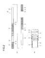
- Figs. 2(a) and 2(b) are views illustrating a radiator hose protective member illustrated in Figs. 1(a) and 1(b)
- Fig. 2(a) is a side view
- Fig. 2(b) is a horizontal cross-sectional view illustrating a partially fractured portion.
- reference sign 1 denotes a radiator hose unit equivalent to the line-shaped assembly.
- the radiator hose unit 1 is attached to an engine (not illustrated) (in other words, a structural body) and a radiator (not illustrated) (in other words, a structural body).
- the radiator hose unit 1 includes a heat source 4 that is a combination of a coolant (that is, a heat source main body) 2 that cools the engine, and a radiator hose (that is, a heat source cover member) 3 through which the coolant 2 heated by the engine flows toward the radiator.
- the radiator hose unit 1 further includes a metal member 5 that is provided to cover an outer surface of the radiator hose 3, and a radiator hose protective member (that is, a heat source protective member) 6 that accommodates and protects the heat source 4 covered with the metal member 5.
- the engine and the radiator are equivalent to structural bodies.
- the radiator hose unit 1 is attached to these structural bodies.
- the radiator hose unit 1 has a portion exposed to the outside of the structural body. That is, the radiator hose unit 1 is attached to the interior and the exterior of the structural body.
- the coolant 2 is liquid for cooling the engine as described above, and flows toward the radiator in a state where the coolant 2 is heated by the engine.
- a well-known coolant is used as the coolant 2.
- the level of the coolant 2 is exemplarily illustrated in the drawings.
- liquid is a configuration element of the heat source 4; however, the present invention is not limited to that configuration, and gas may be a configuration element.
- gas is vapor in boiler equipment.
- the application of the present invention is not limited to the field of transportation equipment, and the present invention can be applied to various fields.
- the radiator hose 3 is a hose (in other words, a tube) made of resin, and is formed so as to have a circular cross section.
- the radiator hose 3 is formed so as to have a predetermined diameter and a predetermined hose thickness.
- the radiator hose 3 is formed to be flexible.
- Connecting means (not illustrated) is attached to each end of the radiator hose 3, and connects the radiator hose 3 and each of the engine and the radiator.
- a well-known radiator hose is used as the radiator hose 3.
- the coolant 2 heated by the engine flows through the radiator hose 3, and a combination of the radiator hose 3 and the coolant 2 is equivalent to the heat source 4.
- the heat source 4 is a straight heat source.
- the heat source 4 may be a heat source that thermally affects the outside, or a heat source through which heat originating from one structural body affects the other structural body.
- the heat source 4 may be broken or damaged by external factors and be required to be protected.
- the metal member 5 is made of a metallic material having good thermal conductivity, and in Embodiment 1, the metal member 5 is formed of a braid into which a plurality of element wires are braided.
- the braided metal member 5 is provided in such a manner as to be in close contact with the outer surface of the radiator hose 3.
- the metal member 5 is not limited to a braid, and for example, the metal member 5 may be formed by wrapping a metal foil or the like around the radiator hose 3.
- the metal member 5 Since the metal member 5 has good thermal conductivity as described above, the metal member 5 serves to draw heat from the heat source 4. That is, the metal member can draw heat.
- the metal member 5 is effective in efficiently transferring heat from the heat source 4 to the radiator hose protective member 6.
- the metal member 5 not only covers the entirety of an outer surface of the heat source 4 as in Embodiment 1, but also may be disposed only at positions in which the metal member 5 is in contact with the radiator hose protective member 6.
- the radiator hose protective member 6 is a tubular body that is made of resin and protects the heat source 4 from external factors, and as illustrated in Figs. 1(a) to 2(b) , the radiator hose protective member 6 is formed in a shape such that the radiator hose protective member 6 has a length required to accommodate the straight heat source 4 and a thickness required to protect the heat source 4.
- the radiator hose protective member 6 is formed in a shape such that the radiator hose protective member 6 does not have a slit connecting an outer surface 7 and an inner surface 8 thereof.
- the radiator hose protective member 6 is illustrated in the long shape; however, the present invention is not limited to that length.
- the radiator hose protective member 6 is formed so as to have a circular cross section.
- the circular cross section is an example, and the radiator hose protective member 6 may have a track-shaped cross section, an elliptical cross section, or a rectangular cross section insofar as the radiator hose protective member 6 with this shape can accommodate the heat source 4 and ensure contact with the heat source 4.
- the radiator hose protective member 6 has a plurality of flexible tube portions (that is, first tube body portions) 9, and a plurality of non-flexible tube portions (that is, second tube body portions) 10 not having the same degree of flexibility as that of the flexible tube portions 9 (in other words, having flexibility lower than that of the flexible tube portion 9).
- the flexible tube portions 9 and the non-flexible tube portions 10 are integrally resin-molded (that is, integrally molded) in such a manner that the entirety thereof is straight in a state where the flexible tube portions 9 are not bent.
- the flexible tube portions 9 and the non-flexible tube portions 10 are disposed in such a manner as to be alternately successive.
- the flexible tube portion 9 is disposed at a position in which the flexible tube portion 9 matches the shape of a mating attachment portion.
- the flexible tube portion 9 is formed so as to have a length such that the flexible tube portion 9 matches the shape of the mating attachment portion. Since the respective lengths of the flexible tube portions 9 are different from each other in an axial direction of the tube, the flexible tube portion 9 can be bent so as to have a necessary length such that the flexible tube portion 9 matches the shape of the mating attachment portion.
- the flexible tube portion 9 can be bent at a desired angle.
- the flexible tube portion 9 is formed in a bellows shape.
- the shape of the flexible tube portion 9 is not particularly limited.
- the flexible tube portion 9 has a concave portion 11 and a convex portion 12 which extend in a circumferential direction, and the concave portions 11 and the convex portions 12 are formed in such a manner as to be alternately successive in the axial direction of the tube. Since the flexible tube portion 9 has the concave portions 11 and the convex portions 12, an inner surface of the flexible tube portion 9 is in point contact with a plurality of regions on the heat source 4 covered with the metal member 5. That is, the flexible tube portion 9 has a relatively small contact area between the inner surface thereof and the heat source 4.
- Portions of the radiator hose protective member 6 are formed in a corrugated shape, the flexible tube portions 9 being respectively disposed in the portions.
- the radiator hose protective member 6 is formed in a shape such that the corrugated tubes are partially formed therein. Since the radiator hose protective member 6 has the corrugated tube portions as described above, the radiator hose protective member 6 can be seen as a "corrugated tube", a “partially corrugated tube", or the like.
- the radiator hose protective member 6 is formed in a shape such that a slit is not provided along the axial direction of the tube (that is, there is no axial split).
- the reason for not providing the slit is that water is prevented from intruding into the radiator hose protective member 6 and waterproof properties improve.
- Another reason for not providing the slit is that the heat source 4 covered with the metal member 5 is prevented from sticking out of the bent portions.
- Still another reason for not providing the slit is that an improvement in the rigidity of the radiator hose protective member 6 is obtained.
- the radiator hose protective member 6 is preferably formed in a shape such that seams are not formed in the circumferential direction. The reasons are the same as in the slit.
- the radiator hose protective member 6 may be split at predetermined positions insofar as the above-mentioned points can satisfied.
- the split members are integrally formed via bonding, welding, or a post attachment member for connecting the split members.
- the post attachment members are used for the integration of the split members, preferably, there is no gap between the heat source 4 and the metal member 5 that covers the heat source 4.
- the non-flexible tube portion 10 is formed as a non-bent portion (the non-bent portion indicating a portion that does not have active flexibility).
- the non-flexible tube portion 10 is formed in a straight shape with a circular cross section.
- the shape of the non-flexible tube portion 10 is not limited to a circular cross section, and may be a track-shaped cross section, an elliptical cross section, or a circular cross section.
- the non-flexible tube portion 10 is formed in a straight shape.
- the non-flexible tube portion 10 can be referred to as a "straight tube portion", a "straight portion”, or the like.
- the non-flexible tube portion 10 is formed as a rigid portion compared to the flexible tube portion 9.
- the non-flexible tube portion 10 is disposed at a position in which the non-flexible tube portion 10 matches the shape of a mating attachment portion, and the non-flexible tube portion 10 is formed so as to have a length such that the non-flexible tube portion 10 matches the shape of the mating attachment portion.
- the non-flexible tube portion 10 is formed in such a manner that the inner surface 8 has a large area in contact with the heat source 4 covered with the metal member 5 compared to that of the flexible tube portion 9. That is, the non-flexible tube portion 10 is formed in such a manner that a contact area per unit length is large in the axial direction of the tube compared to that of the flexible tube portion 9. Specifically, the non-flexible tube portion 10 is formed so as to have a flat surface without concavities and convexities.
- Embodiment 1 a plurality of the non-flexible tube portions 10 are provided, and one of these non-flexible tube portions 10 is formed to be long (refer to Fig. 2(a) ). Since the non-flexible tube portion 10 is formed to be long, it is possible to further increase a contact area between the non-flexible tube portion 10 and the heat source 4 covered with the metal member 5. It is effective in heat dissipation to dispose the long non-flexible tube portion 10 at a position exposed to the atmosphere.
- the metal member 5 draws heat from the heat source 4 to the outside. Since the metal member 5 is in contact with the inner surface 8 of the non-flexible tube portion 10 of the radiator hose protective member 6, the drawn heat is transferred a main body of the radiator hose protective member 6. The heat moves in a direction illustrated by arrow H, and finally, the heat is emitted (in other words, dissipated) from the outer surface 7 of the radiator hose protective member 6.
- the radiator hose protective member 6 is made of resin having good emissivity, it is possible to prevent heat from being trapped in the radiator hose protective member 6 compared to the radiator hose protective member 6 made of pure metal.
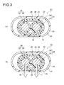
- Figs. 3(a) and 3(b) are views illustrating a wire harness that is a line-shaped assembly of Embodiment 2
- Fig. 3(a) is a vertical cross-sectional view
- Fig. 3(b) is a view illustrating the movement of heat in Fig. 3(a) .
- a wire harness 21 denotes a wire harness equivalent to the line-shaped assembly.
- a wire harness 21 is a high voltage wire harness (that is, a high voltage wire harness) that is routed in a hybrid vehicle (may be an electric vehicle or a typical vehicle).
- the wire harness 21 is routed so as to electrically connect an inverter unit (not illustrated) and a battery (not illustrated).
- the inverter unit is mounted in an engine compartment, and the battery is mounted in a rear portion of the vehicle.
- the wire harness 21 is routed between the front and the rear of the vehicle in a vehicle underfloor region. Accordingly, the wire harness 21 is formed to be long.
- the inverter unit (not illustrated) and the battery (not illustrated) are equivalent to so-called structural bodies.
- the radiator hose unit 1 is attached to these structural bodies.
- the radiator hose unit 1 has a portion exposed to the outside of the structural body. That is, the radiator hose unit 1 is attached to the interior and the exterior of the structural body. This configuration is the same as in Embodiment 3 that will be described later.
- the wire harness 21 includes a high voltage conductive path (that is, a heat source) 22 and an exterior member (that is, a heat source protective member) 23 that accommodates and protects the high voltage conductive path 22.
- a high voltage conductive path that is, a heat source
- an exterior member that is, a heat source protective member
- the high voltage conductive path 22 includes two high voltage circuits 24; a shield member (that is, a metal member) 25 that covers the two high voltage circuits 24; and a sheath (that is, a heat source cover member) 26 that is provided on an outer side of the shield member 25.
- the high voltage circuit 24 is a well-known high voltage electrical wire, and includes a conductor (that is, a heat source main body) 27 and an insulator (that is, a heat source cover member) 28 for covering the conductor 27.
- the conductor 27 is made of copper, a copper alloy, aluminum, an aluminum alloy, or alloys of these materials.
- the conductor 27 may have any one of a conductor structure in which element wires are twisted together, and a bar-shaped conductor structure (for example, a conductor structure having a flat single core or a round single core, and in this case, the electrical wire also has a bar shape) having a rectangular cross section or a round cross section.
- the conductor 27 is formed by extrusion molding the insulator 28 (made of a resin material having insulation properties) on an outer surface of the conductor 27.
- the shield member 25 is an electromagnetic shield member (that is, a shield member acting as a countermeasure for electromagnetic waves) that collectively covers the two high voltage circuits 24, and adopts a well-known cylindrical braid into which a plurality of element wires are braided.
- the shield member 25 is formed so as to have substantially the same length as the full length of the two high voltage circuits 24.
- the shield member 25 may be formed of a metal foil having conductivity, or a member containing the metal foil insofar as the material can act as a countermeasure for electromagnetic waves.
- the shield member 25 is disposed in the heat source cover member while being interposed between the insulator 28 and the sheath 26.
- the sheath 26 is formed by extrusion molding a resin material having insulation properties and a predetermined thickness on an outer side of the shield member 25, and is disposed in an outermost layer of the high voltage conductive path 22.
- the sheath 26 may not be provided, and the shield member 25 may be disposed in the outermost layer.
- the exterior member 23 is a modification of the radiator hose protective member 6 (refer to Figs. 1(a) to 2(b) ) in Embodiment 1. That is, the exterior member 23 is formed by modifying the radiator hose protective member 6 to be flat and to have a track-shaped cross section.
- Reference sign 29 denotes a non-flexible tube portion (that is, a second tube body portion) of the exterior member 23.
- Reference sign 30 denotes an outer surface of the non-flexible tube portion, and reference sign 31 denotes an inner surface thereof.
- a flat surface 32 is formed in the inner surface 31.
- the flat surface 32 is a flat surface without a curved surface, and does not have concavities and convexities.
- the flat surface 32 can be in surface contact with the high voltage conductive path 22, thereby increasing a contact area.
- heat originating from the conductor 27 associated with its energization is drawn to the sheath 26 due to the shield member 25. Since the sheath 26 is in surface contact with the inner surface 31 (that is, the flat surface 32) of the non-flexible tube portion 29 of the exterior member 23, the drawn heat is transferred a main body of the exterior member 23. The heat moves in a direction illustrated by arrow H, and finally, the heat is emitted (in other words, dissipated) from the outer surface 30 of the exterior member 23.
- the exterior member 23 is made of resin having good emissivity, it is possible to prevent heat from being trapped in the exterior member 23 compared to the exterior member 23 made of pure metal.
- the non-flexible tube portion 29 when the long non-flexible tube portion 29 is disposed in the vehicle underfloor region, the non-flexible tube portion 29 extends in a horizontal direction, and thereby only the weight of the high voltage conductive path 22 allows the high voltage conductive path 22 to be in contact with the inner surface 31 (that is, the flat surface 32) of non-flexible tube portion 29.
- Figs. 4(a) and 4(b) are views illustrating a wire harness that is a line-shaped assembly of Embodiment 3
- Fig. 4(a) is a vertical cross-sectional view
- Fig. 4(b) is a vertical cross-sectional view illustrating a comparative example.
- reference sign 41 denotes a wire harness equivalent to the line-shaped assembly.
- a wire harness 41 is routed so as to electrically connect the inverter unit (not illustrated) and a motor unit (not illustrated).
- the wire harness 41 includes three high voltage conductive paths (that is, heat sources) 42 and a flat exterior member (that is, a heat source protective member) 43 that accommodates and protects the three high voltage conductive paths 15 lining up laterally, and has a track-shaped cross section.
- the high voltage conductive path 42 is a high voltage shielded electrical wire, and includes a conductor (that is, a heat source main body) 44 made of metal having conductivity; an insulator (that is, a heat source cover member) 45 that is made of resin, and insulates and covers the conductor 44; a shield member (that is a metal member) 46 that is made of metal and is provided on an outer side of the insulator 45; and a sheath (that is, a heat source cover member) 47 that is made of resin and is provided on an outer side of the shield member 46.
- the exterior member 43 is formed by increasing the lateral length of the exterior member 23 (refer to Figs. 3(a) and 3(b) ) in Embodiment 2.
- Reference sign 48 denotes a non-flexible tube portion (that is, a second tube body portion) of the exterior member 43.
- Reference sign 49 denotes an outer surface of the non-flexible tube portion, and reference sign 50 denotes an inner surface thereof. Since a non-flexible tube portion 48 is formed flat, a flat surface 51 is formed in the inner surface 50. The flat surface 51 can be in contact with each of the three high voltage conductive paths 42, thereby increasing a contact area.
- a comparative example illustrated in Fig. 4(b) only two of the three high voltage conductive paths 42 are in contact with an inner surface 102 of an exterior member 101 having a circular cross section. Accordingly, when the number of high voltage conductive paths 42 increases, the flat exterior member 43 as illustrated in Fig. 4(a) is effective in heat transfer. In addition, the flat exterior member 43 is effective in lowering the height of the wire harness.
- the line-shaped assembly according to the present invention is effective in that heat originating from the heat source can be efficiently transferred to the heat source protective member, and be dissipated.
Landscapes
- Engineering & Computer Science (AREA)
- General Engineering & Computer Science (AREA)
- Mechanical Engineering (AREA)
- Details Of Indoor Wiring (AREA)
- Insulated Conductors (AREA)
- Rigid Pipes And Flexible Pipes (AREA)
- Laminated Bodies (AREA)
Abstract
A heat source protective member (6) is made of resin, and includes a first tube body portion (9) with an inner surface that has a small area per unit length in an axial direction of the tube in contact with a heat source (4), and a second tube body portion (10) with an inner surface that has a contact area larger than that of the first tube body portion (9).
Description
- The present invention relates to a line-shaped assembly that includes a heat source which extends straightly, and a tubular-shaped heat source protective member that accommodates and protects the heat source.
- A heat source may be one of substances in various phases, for example, gas, liquid, and a solid. For example, when a heat source such as gas or liquid is heated, a container or a tube (that is, an object covering a heat source) for the storage and the flow of the heat source is required. Since the touching of a heated solid may become dangerous, the heated solid is required to be coated. As such, the heat source includes gas, liquid, or a solid which is heated, and a cover member that covers the gas, liquid, or solid.
- When the usage patterns of these heat sources are taken into consideration, a protective member is required to protect the heat source. For example, when a heat source is formed in a shape such that the heat source extends straightly, a protective member is formed in a tubular shape to match that shape.
- In various industrial fields, a hose is used for the flow of high-temperature gas or liquid. For example, in the field of transportation equipment, a heat source is equivalent to a combination of a coolant for cooling an engine, and a radiator hose for flowing the coolant heated by the engine to a radiator.
- In an example of a solid instead of the above-described liquid, a heat source is equivalent to an electrical wire or a bundle of electrical wires for the connection of vehicle-mounted equipment. The electrical wire includes a conductor for flowing electricity, and an insulator that covers the conductor. When electricity flows through the conductor, the electrical wire generates heat. A high voltage electrical wire is an example of an electrical wire having a large amount of heat generation (refer to Patent document 1).
- [Patent document 1]
JP-A-2010-51042 - A corrugated tube is an example of a protective member that protects a straight heat source. However, when the heat source is protected using a corrugated tube, heat originating from the heat source may be trapped in the corrugated tube.
- Accordingly, it is an effective countermeasure for this problem to efficiently transfer the heat originating from the heat source to the corrugated tube, and to dissipate the heat through an outer surface of the corrugated tube. However, since the corrugated tube is formed in a bellows shape, a contact area between an inner surface of the corrugated tube and the heat source is small. For this reason, the heat originating from the heat source is unlikely to be efficiently transferred to the corrugated tube. As a result, the corrugated tube cannot be a satisfactory countermeasure.
- Since the entirety of the corrugated tube is bent, when the length of the corrugate tube is long, a portion of the corrugated tube may be bent, which is desired not to be bent much. For this reason, it is necessary to post-attach another rigid member to the corrugate tube.
- The present invention is made in light of these problems, and an object of the present invention is to provide a line-shaped assembly that can efficiently transfer heat originating from a heat source to a heat source protective member, and dissipate the heat.
- In order to achieve this object, a line-shaped assembly according to the present invention has the following characteristics (1) to (8).
- (1) A line-shaped assembly includes a heat source that includes a heat source main body which extends straightly, and a heat source cover member that covers the heat source main body; and a tubular-shaped heat source protective member that accommodates and protects the heat source. The heat source protective member is made of resin, and includes a first tube body portion with an inner surface that has a small area per unit length in an axial direction of the heat source protective member in contact with the heat source, and a second tube body portion with an inner surface that has a contact area larger than that of the first tube body portion.
- In the line-shaped assembly disclosed in (1), the heat source protective member includes the second tube body portion as a configuration member, and a contact area of the heat source protective member with respect to the heat source can be larger than that of the heat source protective member, the entirety of which has a bellows shape. Accordingly, heat originating from the heat source can be efficiently transferred to the heat source protective member. In the line-shaped assembly disclosed in (1), since the heat source protective member is made of resin, attributively, the heat source protective member easily emits heat compared to the heat source protective member made of metal. For example, the first tube body portion preferably has a bellows shape.
- As a result, in the line-shaped assembly disclosed in (1), heat originating from the heat source can be efficiently transferred to the heat source protective member and be dissipated.
- (2) In the line-shaped assembly disclosed (1), the second tube body portion is formed so as to include a flat inner surface.
- In the line-shaped assembly disclosed in (2), since the second tube body portion has a flat inner surface, even when a plurality of the heat sources are provided, the heat sources are brought into contact with each other while lining up side by side, and thereby the heat sources can come into contact with the flat surface.
- As a result, in the line-shaped assembly disclosed in (2), heat originating from the heat source can be efficiently transferred to the heat source protective member.
- (3) In the line-shaped assembly disclosed in (1) or (2), the heat source protective member is integrally molded so that the first tube body portion and the second tube body portion are successive in the axial direction of the heat source protective member.
- In the line-shaped assembly disclosed in (3), since the heat source protective member is made of resin, the heat source protective member can be integrally molded in such a manner that the first tube body portions and the second tube body portions are successive. Accordingly, it is possible to omit a member (that is, a connection member) for connecting the first tube body portion and the second tube body portion. Since the connection member is not required, it is possible to reduce the number of components, and to prevent an occurrence of a step or the like between the first tube body portion and the second tube body portion. As a result, it is possible to prevent an occurrence a state in which the heat source is not in contact with the inner surface of the heat source protective member, that is, an occurrence of a gap therebetween.
- As a result, in the line-shaped assembly disclosed in (3), heat originating from the heat source can be efficiently transferred to the heat source protective member. In addition, it is possible to reduce the number of components.
- (4) In the line-shaped assembly disclosed in any one of (1) to (3), the line-shaped assembly is attached to both of an interior and an exterior of a structural body, and at least a part of the second tube body portion of the heat source protective member is disposed in the exterior of the structural body.
- In the line-shaped assembly disclosed in (4), since at least a part of the second tube body portion is disposed in the exterior of the structural body, the second tube body portion can be exposed to the atmosphere.
- As a result, in the line-shaped assembly disclosed in (4), it is possible to set a good environment by virtue of heat dissipation.
- (5) In the line-shaped assembly disclosed in (4), the line-shaped assembly is disposed in the exterior of the structural body so that the second tube body portion extends in a substantially horizontal direction.
- In the line-shaped assembly disclosed in (5), the weight of the heat source allows the heat source to be in contact with the inner surface of the second tube body portion.
- As a result, in the line-shaped assembly disclosed in (5), it is possible to bring the heat source into good contact with the heat source protective member.
- (6) In the line-shaped assembly disclosed in any one of (1) to (5), a metal member is disposed in the heat source cover member of the heat source while being close to the heat source protective member, or the metal member is disposed on an outer surface of the heat source cover member while being in contact with the heat source protective member.
- In the line-shaped assembly disclosed in (6), heat originating from the heat source can be drawn (in other words, transferred) to the outside by the metal member having good thermal conductivity.
- As a result, in the line-shaped assembly disclosed in (6), heat originating from the heat source can be efficiently transferred to the heat source protective member.
- (7) In the line-shaped assembly disclosed in (6), the heat source is a conductive path, the metal member is a conductive shield member, and the heat source protective member is an exterior member with no slit.
- In the line-shaped assembly disclosed in (7), heat originating from the conductive path can be drawn by the shield member, and thereby heat can be efficiently transferred to the exterior member and be dissipated.
- As a result, the line-shaped assembly disclosed in (7) can be applied to a wire harness that has the shield member and is protected with the exterior member.
- (8) In the line-shaped assembly disclosed in (7), the conductive path is a high voltage conductive path, and the high voltage conductive path and the exterior member are formed to be long so as to be routed from a front side to a rear side of a vehicle floor through under the vehicle floor.
- In the line-shaped assembly disclosed in (8), also when the heat source is a high voltage conductive path having a large amount of heat generation, the generated heat is drawn by the shield member, and thereby the generated heat can be efficiently transferred to the exterior member and be dissipated. In the line-shaped assembly disclosed in (8), since the second tube body portion having a large contact area is disposed in the vehicle underfloor region, it is possible to increase the length of the portion that efficiently dissipates heat. The line-shaped assembly disclosed in (8) can be applied to a long high voltage conductive path and a long exterior member, that is, a long wire harness.
-
-
Figs. 1(a) and 1(b) are views illustrating a radiator hose unit that is a line-shaped assembly of Embodiment 1,Fig. 1(a) is a perspective view illustrating the configuration, andFig. 1(b) is a vertical cross-sectional view. -
Figs. 2(a) and 2(b) are views illustrating a radiator hose protective member illustrated inFigs. 1(a) and 1(b) ,Fig. 2(a) is a side view, andFig. 2(b) is a horizontal cross-sectional view illustrating a partially fractured portion. -
Figs. 3(a) and 3(b) are views illustrating a wire harness that is a line-shaped assembly ofEmbodiment 2,Fig. 3(a) is a vertical cross-sectional view, andFig. 3(b) is a view illustrating the movement of heat inFig. 3(a) . -
Figs. 4(a) and 4(b) are views illustrating a wire harness that is a line-shaped assembly ofEmbodiment 3,Fig. 4(a) is a vertical cross-sectional view, andFig. 4(b) is a vertical cross-sectional view illustrating a comparative example. - According to each embodiment of the present invention which will be described below, a line-shaped assembly adopts a heat source protective member that is made of resin and has a large area in contact with a heat source compared to that of the above-mentioned corrugated tube in the related art.
- Hereinafter, a radiator hose unit between an engine and a radiator will be described as an example of the line-shaped assembly (Embodiment 1). This radiator hose unit adopts a radiator hose protective member that has a large area in contact with a heat source including a coolant and a radiator hose, and in the radiator hose unit, heat of the coolant heated by the engine is efficiently transferred to the radiator hose protective member and is dissipated.
- Thereafter, a wire harness will be described as another example of the line-shaped assembly (Embodiments 2 and 3). This wire harness adopts an exterior member that is made of resin and has a large area in contact with a conductive path, and in this wire harness, heat originating from the conductive path is efficiently transferred to the exterior member and is dissipated. The conductive path includes a metal member that can draw (that is, transfer) heat originating from a core wire (that is, a conductor) to the exterior member.
- Hereinafter, Embodiment 1 will be described with reference to
Figs. 1(a) to 2(b) .Figs. 1(a) and 1(b) are views illustrating a radiator hose unit that is a line-shaped assembly of Embodiment 1,Fig. 1(a) is a perspective view illustrating the configuration, andFig. 1(b) is a vertical cross-sectional view.Figs. 2(a) and 2(b) are views illustrating a radiator hose protective member illustrated inFigs. 1(a) and 1(b) ,Fig. 2(a) is a side view, andFig. 2(b) is a horizontal cross-sectional view illustrating a partially fractured portion. - In
Figs. 1(a) and 1(b) , reference sign 1 denotes a radiator hose unit equivalent to the line-shaped assembly. The radiator hose unit 1 is attached to an engine (not illustrated) (in other words, a structural body) and a radiator (not illustrated) (in other words, a structural body). The radiator hose unit 1 includes aheat source 4 that is a combination of a coolant (that is, a heat source main body) 2 that cools the engine, and a radiator hose (that is, a heat source cover member) 3 through which thecoolant 2 heated by the engine flows toward the radiator. The radiator hose unit 1 further includes ametal member 5 that is provided to cover an outer surface of theradiator hose 3, and a radiator hose protective member (that is, a heat source protective member) 6 that accommodates and protects theheat source 4 covered with themetal member 5. - The engine and the radiator (not illustrated) are equivalent to structural bodies. The radiator hose unit 1 is attached to these structural bodies. The radiator hose unit 1 has a portion exposed to the outside of the structural body. That is, the radiator hose unit 1 is attached to the interior and the exterior of the structural body.
- The
coolant 2 is liquid for cooling the engine as described above, and flows toward the radiator in a state where thecoolant 2 is heated by the engine. A well-known coolant is used as thecoolant 2. The level of thecoolant 2 is exemplarily illustrated in the drawings. - In the example illustrated in Embodiment 1, liquid is a configuration element of the
heat source 4; however, the present invention is not limited to that configuration, and gas may be a configuration element. A specific example of gas is vapor in boiler equipment. As described above, the application of the present invention is not limited to the field of transportation equipment, and the present invention can be applied to various fields. - The
radiator hose 3 is a hose (in other words, a tube) made of resin, and is formed so as to have a circular cross section. Theradiator hose 3 is formed so as to have a predetermined diameter and a predetermined hose thickness. Theradiator hose 3 is formed to be flexible. Connecting means (not illustrated) is attached to each end of theradiator hose 3, and connects theradiator hose 3 and each of the engine and the radiator. In Embodiment 1, a well-known radiator hose is used as theradiator hose 3. - As described above, the
coolant 2 heated by the engine flows through theradiator hose 3, and a combination of theradiator hose 3 and thecoolant 2 is equivalent to theheat source 4. Theheat source 4 is a straight heat source. - The
heat source 4 may be a heat source that thermally affects the outside, or a heat source through which heat originating from one structural body affects the other structural body. Theheat source 4 may be broken or damaged by external factors and be required to be protected. - The
metal member 5 is made of a metallic material having good thermal conductivity, and in Embodiment 1, themetal member 5 is formed of a braid into which a plurality of element wires are braided. The braidedmetal member 5 is provided in such a manner as to be in close contact with the outer surface of theradiator hose 3. Themetal member 5 is not limited to a braid, and for example, themetal member 5 may be formed by wrapping a metal foil or the like around theradiator hose 3. - Since the
metal member 5 has good thermal conductivity as described above, themetal member 5 serves to draw heat from theheat source 4. That is, the metal member can draw heat. Themetal member 5 is effective in efficiently transferring heat from theheat source 4 to the radiator hoseprotective member 6. Themetal member 5 not only covers the entirety of an outer surface of theheat source 4 as in Embodiment 1, but also may be disposed only at positions in which themetal member 5 is in contact with the radiator hoseprotective member 6. - In
Figs. 1(a) to 2(b) , the radiator hoseprotective member 6 is a tubular body that is made of resin and protects theheat source 4 from external factors, and as illustrated inFigs. 1(a) to 2(b) , the radiator hoseprotective member 6 is formed in a shape such that the radiator hoseprotective member 6 has a length required to accommodate thestraight heat source 4 and a thickness required to protect theheat source 4. The radiator hoseprotective member 6 is formed in a shape such that the radiator hoseprotective member 6 does not have a slit connecting anouter surface 7 and aninner surface 8 thereof. In Embodiment 1, the radiator hoseprotective member 6 is illustrated in the long shape; however, the present invention is not limited to that length. - In Embodiment 1, the radiator hose
protective member 6 is formed so as to have a circular cross section. The circular cross section is an example, and the radiator hoseprotective member 6 may have a track-shaped cross section, an elliptical cross section, or a rectangular cross section insofar as the radiator hoseprotective member 6 with this shape can accommodate theheat source 4 and ensure contact with theheat source 4. The radiator hoseprotective member 6 has a plurality of flexible tube portions (that is, first tube body portions) 9, and a plurality of non-flexible tube portions (that is, second tube body portions) 10 not having the same degree of flexibility as that of the flexible tube portions 9 (in other words, having flexibility lower than that of the flexible tube portion 9). - The
flexible tube portions 9 and thenon-flexible tube portions 10 are integrally resin-molded (that is, integrally molded) in such a manner that the entirety thereof is straight in a state where theflexible tube portions 9 are not bent. Theflexible tube portions 9 and thenon-flexible tube portions 10 are disposed in such a manner as to be alternately successive. - The
flexible tube portion 9 is disposed at a position in which theflexible tube portion 9 matches the shape of a mating attachment portion. Theflexible tube portion 9 is formed so as to have a length such that theflexible tube portion 9 matches the shape of the mating attachment portion. Since the respective lengths of theflexible tube portions 9 are different from each other in an axial direction of the tube, theflexible tube portion 9 can be bent so as to have a necessary length such that theflexible tube portion 9 matches the shape of the mating attachment portion. Theflexible tube portion 9 can be bent at a desired angle. - It is possible to form the
flexible tube portion 9 in a bent shape, and to return theflexible tube portion 9 to an original straight shape. - The
flexible tube portion 9 is formed in a bellows shape. The shape of theflexible tube portion 9 is not particularly limited. Specifically, theflexible tube portion 9 has aconcave portion 11 and aconvex portion 12 which extend in a circumferential direction, and theconcave portions 11 and theconvex portions 12 are formed in such a manner as to be alternately successive in the axial direction of the tube. Since theflexible tube portion 9 has theconcave portions 11 and theconvex portions 12, an inner surface of theflexible tube portion 9 is in point contact with a plurality of regions on theheat source 4 covered with themetal member 5. That is, theflexible tube portion 9 has a relatively small contact area between the inner surface thereof and theheat source 4. - Portions of the radiator hose
protective member 6 are formed in a corrugated shape, theflexible tube portions 9 being respectively disposed in the portions. In other words, the radiator hoseprotective member 6 is formed in a shape such that the corrugated tubes are partially formed therein. Since the radiator hoseprotective member 6 has the corrugated tube portions as described above, the radiator hoseprotective member 6 can be seen as a "corrugated tube", a "partially corrugated tube", or the like. - The radiator hose
protective member 6 is formed in a shape such that a slit is not provided along the axial direction of the tube (that is, there is no axial split). The reason for not providing the slit is that water is prevented from intruding into the radiator hoseprotective member 6 and waterproof properties improve. Another reason for not providing the slit is that theheat source 4 covered with themetal member 5 is prevented from sticking out of the bent portions. Still another reason for not providing the slit is that an improvement in the rigidity of the radiator hoseprotective member 6 is obtained. In addition, the radiator hoseprotective member 6 is preferably formed in a shape such that seams are not formed in the circumferential direction. The reasons are the same as in the slit. - The radiator hose
protective member 6 may be split at predetermined positions insofar as the above-mentioned points can satisfied. In this case, the split members are integrally formed via bonding, welding, or a post attachment member for connecting the split members. In the structure where the post attachment members are used for the integration of the split members, preferably, there is no gap between theheat source 4 and themetal member 5 that covers theheat source 4. - The
non-flexible tube portion 10 is formed as a non-bent portion (the non-bent portion indicating a portion that does not have active flexibility). Thenon-flexible tube portion 10 is formed in a straight shape with a circular cross section. The shape of thenon-flexible tube portion 10 is not limited to a circular cross section, and may be a track-shaped cross section, an elliptical cross section, or a circular cross section. - As illustrated in
Figs. 1(a) to 2(b) , thenon-flexible tube portion 10 is formed in a straight shape. For this reason, thenon-flexible tube portion 10 can be referred to as a "straight tube portion", a "straight portion", or the like. Thenon-flexible tube portion 10 is formed as a rigid portion compared to theflexible tube portion 9. Thenon-flexible tube portion 10 is disposed at a position in which thenon-flexible tube portion 10 matches the shape of a mating attachment portion, and thenon-flexible tube portion 10 is formed so as to have a length such that thenon-flexible tube portion 10 matches the shape of the mating attachment portion. Thenon-flexible tube portion 10 is formed in such a manner that theinner surface 8 has a large area in contact with theheat source 4 covered with themetal member 5 compared to that of theflexible tube portion 9. That is, thenon-flexible tube portion 10 is formed in such a manner that a contact area per unit length is large in the axial direction of the tube compared to that of theflexible tube portion 9. Specifically, thenon-flexible tube portion 10 is formed so as to have a flat surface without concavities and convexities. - In Embodiment 1, a plurality of the
non-flexible tube portions 10 are provided, and one of thesenon-flexible tube portions 10 is formed to be long (refer toFig. 2(a) ). Since thenon-flexible tube portion 10 is formed to be long, it is possible to further increase a contact area between thenon-flexible tube portion 10 and theheat source 4 covered with themetal member 5. It is effective in heat dissipation to dispose the longnon-flexible tube portion 10 at a position exposed to the atmosphere. - With the above-mentioned configuration and structure, as illustrated in
Fig. 1(b) , themetal member 5 draws heat from theheat source 4 to the outside. Since themetal member 5 is in contact with theinner surface 8 of thenon-flexible tube portion 10 of the radiator hoseprotective member 6, the drawn heat is transferred a main body of the radiator hoseprotective member 6. The heat moves in a direction illustrated by arrow H, and finally, the heat is emitted (in other words, dissipated) from theouter surface 7 of the radiator hoseprotective member 6. - As described above with reference to
Figs. 1(a) to 2(b) , in the radiator hose unit 1, since it is possible to increase a contact area via theinner surface 8 of thenon-flexible tube portion 10, heat originating from theheat source 4 can be efficiently transferred to the radiator hoseprotective member 6 and be dissipated. - In the radiator hose unit 1, since the radiator hose
protective member 6 is made of resin having good emissivity, it is possible to prevent heat from being trapped in the radiator hoseprotective member 6 compared to the radiator hoseprotective member 6 made of pure metal. - Hereinafter,
Embodiment 2 will be described with reference toFigs. 3(a) and 3(b). Figs. 3(a) and 3(b) are views illustrating a wire harness that is a line-shaped assembly ofEmbodiment 2,Fig. 3(a) is a vertical cross-sectional view, andFig. 3(b) is a view illustrating the movement of heat inFig. 3(a) . - In
Figs. 3(a) and 3(b) ,reference sign 21 denotes a wire harness equivalent to the line-shaped assembly. Here, awire harness 21 is a high voltage wire harness (that is, a high voltage wire harness) that is routed in a hybrid vehicle (may be an electric vehicle or a typical vehicle). - The
wire harness 21 is routed so as to electrically connect an inverter unit (not illustrated) and a battery (not illustrated). The inverter unit is mounted in an engine compartment, and the battery is mounted in a rear portion of the vehicle. Thewire harness 21 is routed between the front and the rear of the vehicle in a vehicle underfloor region. Accordingly, thewire harness 21 is formed to be long. - The inverter unit (not illustrated) and the battery (not illustrated) are equivalent to so-called structural bodies. The radiator hose unit 1 is attached to these structural bodies. The radiator hose unit 1 has a portion exposed to the outside of the structural body. That is, the radiator hose unit 1 is attached to the interior and the exterior of the structural body. This configuration is the same as in
Embodiment 3 that will be described later. - The
wire harness 21 includes a high voltage conductive path (that is, a heat source) 22 and an exterior member (that is, a heat source protective member) 23 that accommodates and protects the high voltageconductive path 22. - The high voltage
conductive path 22 includes twohigh voltage circuits 24; a shield member (that is, a metal member) 25 that covers the twohigh voltage circuits 24; and a sheath (that is, a heat source cover member) 26 that is provided on an outer side of theshield member 25. This configuration is merely an example. Here, thehigh voltage circuit 24 is a well-known high voltage electrical wire, and includes a conductor (that is, a heat source main body) 27 and an insulator (that is, a heat source cover member) 28 for covering theconductor 27. - The
conductor 27 is made of copper, a copper alloy, aluminum, an aluminum alloy, or alloys of these materials. Theconductor 27 may have any one of a conductor structure in which element wires are twisted together, and a bar-shaped conductor structure (for example, a conductor structure having a flat single core or a round single core, and in this case, the electrical wire also has a bar shape) having a rectangular cross section or a round cross section. Theconductor 27 is formed by extrusion molding the insulator 28 (made of a resin material having insulation properties) on an outer surface of theconductor 27. - Here, the
shield member 25 is an electromagnetic shield member (that is, a shield member acting as a countermeasure for electromagnetic waves) that collectively covers the twohigh voltage circuits 24, and adopts a well-known cylindrical braid into which a plurality of element wires are braided. Theshield member 25 is formed so as to have substantially the same length as the full length of the twohigh voltage circuits 24. For example, theshield member 25 may be formed of a metal foil having conductivity, or a member containing the metal foil insofar as the material can act as a countermeasure for electromagnetic waves. - The
shield member 25 is disposed in the heat source cover member while being interposed between theinsulator 28 and thesheath 26. - The
sheath 26 is formed by extrusion molding a resin material having insulation properties and a predetermined thickness on an outer side of theshield member 25, and is disposed in an outermost layer of the high voltageconductive path 22. Thesheath 26 may not be provided, and theshield member 25 may be disposed in the outermost layer. - The
exterior member 23 is a modification of the radiator hose protective member 6 (refer toFigs. 1(a) to 2(b) ) in Embodiment 1. That is, theexterior member 23 is formed by modifying the radiator hoseprotective member 6 to be flat and to have a track-shaped cross section.Reference sign 29 denotes a non-flexible tube portion (that is, a second tube body portion) of theexterior member 23.Reference sign 30 denotes an outer surface of the non-flexible tube portion, andreference sign 31 denotes an inner surface thereof. - Since a
non-flexible tube portion 29 is formed flat, aflat surface 32 is formed in theinner surface 31. Theflat surface 32 is a flat surface without a curved surface, and does not have concavities and convexities. Theflat surface 32 can be in surface contact with the high voltageconductive path 22, thereby increasing a contact area. - With the above-mentioned configuration and structure, heat originating from the
conductor 27 associated with its energization is drawn to thesheath 26 due to theshield member 25. Since thesheath 26 is in surface contact with the inner surface 31 (that is, the flat surface 32) of thenon-flexible tube portion 29 of theexterior member 23, the drawn heat is transferred a main body of theexterior member 23. The heat moves in a direction illustrated by arrow H, and finally, the heat is emitted (in other words, dissipated) from theouter surface 30 of theexterior member 23. - As described above with reference to
Figs. 3(a) and 3(b) , in thewire harness 21, since it is possible to increase a contact area via theinner surface 31 of thenon-flexible tube portion 29, heat originating from the high voltageconductive path 22 can be efficiently transferred to theexterior member 23 and be dissipated. - In the
wire harness 21, since theexterior member 23 is made of resin having good emissivity, it is possible to prevent heat from being trapped in theexterior member 23 compared to theexterior member 23 made of pure metal. - In regard to a routing path of the
wire harness 21, when the longnon-flexible tube portion 29, that is, the portion having a large area in contact with the heat source, is disposed in the vehicle underfloor region, heat can be efficiently dissipated. - In addition, when the long
non-flexible tube portion 29 is disposed in the vehicle underfloor region, thenon-flexible tube portion 29 extends in a horizontal direction, and thereby only the weight of the high voltageconductive path 22 allows the high voltageconductive path 22 to be in contact with the inner surface 31 (that is, the flat surface 32) ofnon-flexible tube portion 29. - Hereinafter,
Embodiment 3 will be described with reference toFigs. 4(a) to 4(b). Figs. 4(a) and 4(b) are views illustrating a wire harness that is a line-shaped assembly ofEmbodiment 3,Fig. 4(a) is a vertical cross-sectional view, andFig. 4(b) is a vertical cross-sectional view illustrating a comparative example. - In
Fig. 4(a) ,reference sign 41 denotes a wire harness equivalent to the line-shaped assembly. Awire harness 41 is routed so as to electrically connect the inverter unit (not illustrated) and a motor unit (not illustrated). Thewire harness 41 includes three high voltage conductive paths (that is, heat sources) 42 and a flat exterior member (that is, a heat source protective member) 43 that accommodates and protects the three high voltage conductive paths 15 lining up laterally, and has a track-shaped cross section. - The high voltage
conductive path 42 is a high voltage shielded electrical wire, and includes a conductor (that is, a heat source main body) 44 made of metal having conductivity; an insulator (that is, a heat source cover member) 45 that is made of resin, and insulates and covers theconductor 44; a shield member (that is a metal member) 46 that is made of metal and is provided on an outer side of theinsulator 45; and a sheath (that is, a heat source cover member) 47 that is made of resin and is provided on an outer side of theshield member 46. - The
exterior member 43 is formed by increasing the lateral length of the exterior member 23 (refer toFigs. 3(a) and 3(b) ) inEmbodiment 2.Reference sign 48 denotes a non-flexible tube portion (that is, a second tube body portion) of theexterior member 43.Reference sign 49 denotes an outer surface of the non-flexible tube portion, andreference sign 50 denotes an inner surface thereof. Since anon-flexible tube portion 48 is formed flat, aflat surface 51 is formed in theinner surface 50. Theflat surface 51 can be in contact with each of the three high voltageconductive paths 42, thereby increasing a contact area. - With the above-mentioned configuration and structure, heat originating from the energized
conductor 44 is drawn to thesheath 47 due to theshield member 46. Since thesheath 47 is in contact with the inner surface 50 (that is, the flat surface 51) of thenon-flexible tube portion 48 of theexterior member 43, the drawn heat is transferred a main body of theexterior member 43. Finally, the heat is emitted (in other words, dissipated) from theouter surface 49 of theexterior member 43. - As described above with reference to
Figs. 4(a) and 4(b) , in thewire harness 41, since it is possible to increase a contact area via theinner surface 50 of thenon-flexible tube portion 48, heat originating from the high voltageconductive path 42 can be efficiently transferred to theexterior member 43 and be dissipated. - In a comparative example illustrated in
Fig. 4(b) , only two of the three high voltageconductive paths 42 are in contact with aninner surface 102 of anexterior member 101 having a circular cross section. Accordingly, when the number of high voltageconductive paths 42 increases, theflat exterior member 43 as illustrated inFig. 4(a) is effective in heat transfer. In addition, theflat exterior member 43 is effective in lowering the height of the wire harness. - Various modifications can be made to the present invention insofar as the modifications do not depart from the main spirit of the present invention.
- Hereinafter, the configuration of the line-shaped assembly according to the embodiments will be summarized.
- (1) A line-shaped assembly (a radiator hose unit 1, a
wire harness 21, or a wire harness 41) according to an embodiment includes a heat source (aheat source 4, a high voltageconductive path 22, or a high voltage conductive path 42) that includes a heat source main body (acoolant 2, aconductor 27, or a conductor 44) extending straightly, and a heat source cover member (aradiator hose 3, asheath 26, or a sheath 47) covering the heat source main body; and a tubular-shaped heat source protective member (a radiator hoseprotective member 6, anexterior member 23, or an exterior member 43) that accommodates and protects the heat source. The heat source protective member is made of resin, and includes a first tube body portion (a flexible tube portion 9) with an inner surface that has a small area per unit length in an axial direction of the heat source protective member in contact with the heat source, and a second tube body portion (anon-flexible tube portion 10, anon-flexible tube portion 29, or a non-flexible tube portion 48) with an inner surface that has a contact area larger than that of the first tube body portion. - (2) In the line-shaped assembly (the
wire harness 21 or the wire harness 41) according to the embodiment, the second tube body portion (thenon-flexible tube portion 29 or the non-flexible tube portion 48) is formed so as to include a flat inner surface (32 or 51). - (3) In the line-shaped assembly (the radiator hose unit 1, the
wire harness 21, or the wire harness 41) according to the embodiment, the heat source protective member (the radiator hoseprotective member 6, theexterior member 23, or the exterior member 43) is integrally molded in such a manner that the first tube body portion (the flexible tube portions 9) and the second tube body portion (thenon-flexible tube portions 10, thenon-flexible tube portions 29, or the non-flexible tube portions 48) are successive in the axial direction of the heat source protective member. - (4) The line-shaped assembly (the radiator hose unit 1, the
wire harness 21, or the wire harness 41) according to the embodiment is attached to an interior and exterior of a structural body (for example, an engine, a radiator, an inverter unit, or a battery), and at least a part of the second tube body portion (thenon-flexible tube portions 10, thenon-flexible tube portions 29, or the non-flexible tube portions 48) of the heat source protective member (the radiator hoseprotective member 6, theexterior member 23, or the exterior member 43) is disposed in the exterior of the structural body. - (5) The line-shaped assembly (the radiator hose unit 1, the
wire harness 21, or the wire harness 41) according to the embodiment is disposed in the exterior of the structural body so that the second tube body portion (thenon-flexible tube portions 10, thenon-flexible tube portions 29, or the non-flexible tube portions 48) extends in a substantially horizontal direction. - (6) In the line-shaped assembly (the
wire harness 21 or the wire harness 41) according to the embodiment, the metal member (theshield member 25 or the shield member 46) is disposed in the heat source cover member (thesheath 26 or the sheath 47) of the heat source (the high voltageconductive path 22 or the high voltage conductive path 42) while being close to the heat source protective member (theexterior member 23 or the exterior member 43). In the line-shaped assembly (the radiator hose 1) according to the embodiment, themetal member 5 is disposed on an outer surface of the heat source cover member (the radiator hose 3) while being in contact with the heat source protective member (the radiator hose protective member 6). - (7) In the line-shaped assembly (the
wire harness 21 or the wire harness 41) according to the embodiment, the heat source is a conductive path (the high voltageconductive path 22 or the high voltage conductive path 42), the metal member is a conductive shied member (theshield member 25 or the shield member 46), and the heat source protective member is an exterior member (theexterior member 23 or the exterior member 43) with no slit. - (8) In the line-shaped assembly (the
wire harness 21 or the wire harness 41) according to the embodiment, the conductive path is a high voltage conductive path (the high voltageconductive path 22 or the high voltage conductive path 42), and the high voltage conductive path and the exterior member (theexterior member 23 or the exterior member 43) are formed to be long so as to be routed from a front side to a rear side of an vehicle floor through under the vehicle floor. - This application is based on Japanese Patent Application No
2012-280595 filed on December 25, 2012 - The line-shaped assembly according to the present invention is effective in that heat originating from the heat source can be efficiently transferred to the heat source protective member, and be dissipated.
-
- 1:
- radiator hose unit (line-shaped assembly)
- 2:
- coolant (heat source main body)
- 3:
- radiator hose (heat source cover member)
- 4:
- heat source
- 5:
- metal member
- 6:
- radiator hose protective member (heat source protective member)
- 7:
- outer surface
- 8:
- inner surface
- 9:
- flexible tube portion (first tube body portion)
- 10:
- non-flexible tube portion (second tube body portion)
- 11:
- concave portion
- 12:
- convex portion
- 21:
- wire harness (line-shaped assembly)
- 22:
- high voltage conductive path (heat source, conductive path)
- 23:
- exterior member (heat source protective member)
- 24:
- high voltage circuit
- 25:
- shield member (metal member)
- 26:
- sheath (heat source cover member)
- 27:
- conductor (heat source main body)
- 28:
- insulator (heat source cover member)
- 29:
- non-flexible tube portion (second tube body portion)
- 30:
- outer surface
- 31:
- inner surface
- 32:
- flat surface
- 41:
- wire harness (line-shaped assembly)
- 42:
- high voltage conductive path (heat source)
- 43:
- exterior member (heat source protective member)
- 44:
- conductor (heat source main body)
- 45:
- insulator (heat source cover member)
- 46:
- shield member (metal member)
- 47:
- sheath (heat source cover member)
- 48:
- non-flexible tube portion (second tube body portion)
- 49:
- outer surface
- 50:
- inner surface
- 51:
- flat surface
Claims (8)
- A line-shaped assembly comprising:a heat source that includes a heat source main body extending straightly, and a heat source cover member covering the heat source main body; anda tubular-shaped heat source protective member that accommodates and protects the heat source,wherein the heat source protective member is made of resin, and includes a first tube body portion with an inner surface that has a small area per unit length in an axial direction of the heat source protective member in contact with the heat source, and a second tube body portion with an inner surface that has a contact area larger than that of the first tube body portion.
- The line-shaped assembly according to claim 1, wherein the second tube body portion is formed so as to include a flat inner surface.
- The line-shaped assembly according to claim 1 or 2, wherein the heat source protective member is integrally molded so that the first tube body portion and the second tube body portion are successive in the axial direction of the heat source protective member.
- The line-shaped assembly according to any one of claims 1 to 3, wherein the line-shaped assembly is attached to an interior and an exterior of a structural body; and
wherein at least a part of the second tube body portion of the heat source protective member is disposed in exterior of the structural body. - The line-shaped assembly according to claim 4, wherein the line-shaped assembly is disposed in the exterior of the structural body so that the second tube body portion extends in a substantially horizontal direction.
- The line-shaped assembly according to any one of claims 1 to 5, wherein a metal member is disposed in the heat source cover member of the heat source while being close to the heat source protective member, or the metal member is disposed on an outer surface of the heat source cover member while being in contact with the heat source protective member.
- The line-shaped assembly according to claim 6, wherein the heat source is a conductive path;
wherein the metal member is a conductive shield member; and wherein the heat source protective member is an exterior member with no slit. - The line-shaped assembly according to claim 7, wherein the conductive path is a high voltage conductive path; and
wherein the high voltage conductive path and the exterior member are formed to be long so as to be routed from a front side to a rear side of a vehicle floor through under the vehicle floor.
Applications Claiming Priority (2)
| Application Number | Priority Date | Filing Date | Title |
|---|---|---|---|
| JP2012280595A JP5999428B2 (en) | 2012-12-25 | 2012-12-25 | Linear assembly |
| PCT/JP2013/083459 WO2014103749A1 (en) | 2012-12-25 | 2013-12-13 | Line-shaped assembly |
Publications (1)
| Publication Number | Publication Date |
|---|---|
| EP2924328A1 true EP2924328A1 (en) | 2015-09-30 |
Family
ID=51020837
Family Applications (1)
| Application Number | Title | Priority Date | Filing Date |
|---|---|---|---|
| EP13868875.9A Withdrawn EP2924328A1 (en) | 2012-12-25 | 2013-12-13 | Line-shaped assembly |
Country Status (5)
| Country | Link |
|---|---|
| US (1) | US10784017B2 (en) |
| EP (1) | EP2924328A1 (en) |
| JP (1) | JP5999428B2 (en) |
| CN (1) | CN104870876A (en) |
| WO (1) | WO2014103749A1 (en) |
Families Citing this family (3)
| Publication number | Priority date | Publication date | Assignee | Title |
|---|---|---|---|---|
| JP6590845B2 (en) * | 2017-02-27 | 2019-10-16 | 矢崎総業株式会社 | Exterior member and wire harness |
| JP7131439B2 (en) * | 2019-03-07 | 2022-09-06 | 株式会社オートネットワーク技術研究所 | Exterior materials and wire harnesses |
| JP2021081129A (en) * | 2019-11-19 | 2021-05-27 | 三菱重工業株式会社 | duct |
Family Cites Families (17)
| Publication number | Priority date | Publication date | Assignee | Title |
|---|---|---|---|---|
| JPS61149682A (en) * | 1984-12-21 | 1986-07-08 | 住友電気工業株式会社 | Composite pipe, manufacture thereof and heat pipe utilizing said manufacture |
| IT219178Z2 (en) * | 1989-12-20 | 1992-12-17 | F.I.S.T. S.P.A. | FLEXIBLE CONDUCT FOR CIRCUITS OF CIRCULATION OF THE COOLANT LIQUID OF A VEHICLE ENGINE. |
| US5850855A (en) * | 1990-01-09 | 1998-12-22 | Ems-Inventa Ag | Flexible coolant conduit and method of making same |
| US5469892A (en) * | 1992-04-14 | 1995-11-28 | Itt Automotive, Inc. | Corrugated polymeric tubing having at least three layers with at least two respective layers composed of polymeric materials dissimilar to one another |
| US20040076783A1 (en) * | 2002-10-22 | 2004-04-22 | Andrew Norman | Corrugated liquid and vapor carrying fuel tubes and method |
| JP2004224156A (en) * | 2003-01-22 | 2004-08-12 | Honda Motor Co Ltd | Structure for holding power cable for vehicle |
| JP4123986B2 (en) * | 2003-03-10 | 2008-07-23 | 住友電装株式会社 | Wiring harness wiring structure |
| US6983769B2 (en) * | 2003-06-23 | 2006-01-10 | Tokai Rubber Industries, Ltd. | Vibration absorbing hose |
| JP4802449B2 (en) * | 2004-02-17 | 2011-10-26 | 住友電気工業株式会社 | Shielded cable |
| JP4732720B2 (en) * | 2004-07-15 | 2011-07-27 | 東海ゴム工業株式会社 | Refrigerant transport hose |
| JP5292016B2 (en) | 2008-08-19 | 2013-09-18 | 矢崎総業株式会社 | Protector and wire harness |
| JP5530690B2 (en) * | 2009-09-24 | 2014-06-25 | 矢崎総業株式会社 | Wire harness |
| JP5572372B2 (en) * | 2009-12-07 | 2014-08-13 | 矢崎総業株式会社 | Wire harness wiring structure and wire harness |
| JP2011134667A (en) * | 2009-12-25 | 2011-07-07 | Autonetworks Technologies Ltd | Wire harness |
| JP5491224B2 (en) * | 2010-02-05 | 2014-05-14 | 矢崎総業株式会社 | Wire harness |
| JP5877492B2 (en) * | 2010-07-21 | 2016-03-08 | 日産自動車株式会社 | Fuel cell system and operation method thereof |
| JP5804744B2 (en) * | 2011-03-30 | 2015-11-04 | 古河電気工業株式会社 | Wire harness protection tube and wire harness protection member |
-
2012
- 2012-12-25 JP JP2012280595A patent/JP5999428B2/en not_active Expired - Fee Related
-
2013
- 2013-12-13 EP EP13868875.9A patent/EP2924328A1/en not_active Withdrawn
- 2013-12-13 WO PCT/JP2013/083459 patent/WO2014103749A1/en active Application Filing
- 2013-12-13 CN CN201380067890.1A patent/CN104870876A/en active Pending
-
2015
- 2015-06-25 US US14/749,742 patent/US10784017B2/en active Active
Non-Patent Citations (1)
| Title |
|---|
| See references of WO2014103749A1 * |
Also Published As
| Publication number | Publication date |
|---|---|
| CN104870876A (en) | 2015-08-26 |
| JP2014124774A (en) | 2014-07-07 |
| US10784017B2 (en) | 2020-09-22 |
| JP5999428B2 (en) | 2016-09-28 |
| US20150294765A1 (en) | 2015-10-15 |
| WO2014103749A1 (en) | 2014-07-03 |
Similar Documents
| Publication | Publication Date | Title |
|---|---|---|
| EP2533252B1 (en) | Wire harness | |
| US10081316B2 (en) | Wire harness | |
| EP2894738B1 (en) | Wire harness | |
| US9742166B2 (en) | Wire harness | |
| US9490613B2 (en) | Wire harness | |
| US20090167078A1 (en) | Vehicle conductor | |
| US20110133548A1 (en) | Wiring harness and a method of providing wiring structure of the same | |
| CN110785821B (en) | Wire harness | |
| JP5691642B2 (en) | Shield conductor | |
| WO2012032796A1 (en) | Wiring structure of motor vehicle | |
| JP2013243900A (en) | Wire harness | |
| JP2011134667A (en) | Wire harness | |
| JP4787535B2 (en) | Mounting structure for shield conductor | |
| EP2894740B1 (en) | Wire harness | |
| JP2011168104A (en) | Vehicle electrical wire | |
| US10784017B2 (en) | Line-shaped assembly | |
| US10596983B2 (en) | Wire harness | |
| JP6186615B2 (en) | Wire harness | |
| US11745674B2 (en) | Wire harness with exterior tube, first protective body and second protective body | |
| WO2020026884A1 (en) | Wire harness | |
| JP6127312B2 (en) | Wire harness | |
| JP2017055537A (en) | Wiring structure for wiring harness | |
| JP7315044B2 (en) | wire harness | |
| WO2016021026A1 (en) | Wire harness | |
| JP2020108185A (en) | Exterior member and wire harness |
Legal Events
| Date | Code | Title | Description |
|---|---|---|---|
| PUAI | Public reference made under article 153(3) epc to a published international application that has entered the european phase |
Free format text: ORIGINAL CODE: 0009012 |
|
| 17P | Request for examination filed |
Effective date: 20150623 |
|
| AK | Designated contracting states |
Kind code of ref document: A1 Designated state(s): AL AT BE BG CH CY CZ DE DK EE ES FI FR GB GR HR HU IE IS IT LI LT LU LV MC MK MT NL NO PL PT RO RS SE SI SK SM TR |
|
| AX | Request for extension of the european patent |
Extension state: BA ME |
|
| DAX | Request for extension of the european patent (deleted) | ||
| STAA | Information on the status of an ep patent application or granted ep patent |
Free format text: STATUS: THE APPLICATION IS DEEMED TO BE WITHDRAWN |
|
| 18D | Application deemed to be withdrawn |
Effective date: 20160701 |