EP2924280B1 - Method and device for controlling floating body wind power electricity generation device, and floating body wind power electricity generation device - Google Patents
Method and device for controlling floating body wind power electricity generation device, and floating body wind power electricity generation device Download PDFInfo
- Publication number
- EP2924280B1 EP2924280B1 EP12891221.9A EP12891221A EP2924280B1 EP 2924280 B1 EP2924280 B1 EP 2924280B1 EP 12891221 A EP12891221 A EP 12891221A EP 2924280 B1 EP2924280 B1 EP 2924280B1
- Authority
- EP
- European Patent Office
- Prior art keywords
- wind turbine
- turbine generator
- change rate
- pitch angle
- pitch
- Prior art date
- Legal status (The legal status is an assumption and is not a legal conclusion. Google has not performed a legal analysis and makes no representation as to the accuracy of the status listed.)
- Active
Links
Images





Classifications
-
- F—MECHANICAL ENGINEERING; LIGHTING; HEATING; WEAPONS; BLASTING
- F03—MACHINES OR ENGINES FOR LIQUIDS; WIND, SPRING, OR WEIGHT MOTORS; PRODUCING MECHANICAL POWER OR A REACTIVE PROPULSIVE THRUST, NOT OTHERWISE PROVIDED FOR
- F03D—WIND MOTORS
- F03D7/00—Controlling wind motors
- F03D7/02—Controlling wind motors the wind motors having rotation axis substantially parallel to the air flow entering the rotor
- F03D7/0244—Controlling wind motors the wind motors having rotation axis substantially parallel to the air flow entering the rotor for braking
- F03D7/0252—Controlling wind motors the wind motors having rotation axis substantially parallel to the air flow entering the rotor for braking with aerodynamic drag devices on the blades
-
- F—MECHANICAL ENGINEERING; LIGHTING; HEATING; WEAPONS; BLASTING
- F03—MACHINES OR ENGINES FOR LIQUIDS; WIND, SPRING, OR WEIGHT MOTORS; PRODUCING MECHANICAL POWER OR A REACTIVE PROPULSIVE THRUST, NOT OTHERWISE PROVIDED FOR
- F03D—WIND MOTORS
- F03D7/00—Controlling wind motors
- F03D7/02—Controlling wind motors the wind motors having rotation axis substantially parallel to the air flow entering the rotor
- F03D7/022—Adjusting aerodynamic properties of the blades
- F03D7/0224—Adjusting blade pitch
-
- F—MECHANICAL ENGINEERING; LIGHTING; HEATING; WEAPONS; BLASTING
- F03—MACHINES OR ENGINES FOR LIQUIDS; WIND, SPRING, OR WEIGHT MOTORS; PRODUCING MECHANICAL POWER OR A REACTIVE PROPULSIVE THRUST, NOT OTHERWISE PROVIDED FOR
- F03D—WIND MOTORS
- F03D7/00—Controlling wind motors
- F03D7/02—Controlling wind motors the wind motors having rotation axis substantially parallel to the air flow entering the rotor
- F03D7/0244—Controlling wind motors the wind motors having rotation axis substantially parallel to the air flow entering the rotor for braking
-
- F—MECHANICAL ENGINEERING; LIGHTING; HEATING; WEAPONS; BLASTING
- F03—MACHINES OR ENGINES FOR LIQUIDS; WIND, SPRING, OR WEIGHT MOTORS; PRODUCING MECHANICAL POWER OR A REACTIVE PROPULSIVE THRUST, NOT OTHERWISE PROVIDED FOR
- F03D—WIND MOTORS
- F03D7/00—Controlling wind motors
- F03D7/02—Controlling wind motors the wind motors having rotation axis substantially parallel to the air flow entering the rotor
- F03D7/026—Controlling wind motors the wind motors having rotation axis substantially parallel to the air flow entering the rotor for starting-up
-
- F—MECHANICAL ENGINEERING; LIGHTING; HEATING; WEAPONS; BLASTING
- F03—MACHINES OR ENGINES FOR LIQUIDS; WIND, SPRING, OR WEIGHT MOTORS; PRODUCING MECHANICAL POWER OR A REACTIVE PROPULSIVE THRUST, NOT OTHERWISE PROVIDED FOR
- F03D—WIND MOTORS
- F03D7/00—Controlling wind motors
- F03D7/02—Controlling wind motors the wind motors having rotation axis substantially parallel to the air flow entering the rotor
- F03D7/04—Automatic control; Regulation
-
- B—PERFORMING OPERATIONS; TRANSPORTING
- B63—SHIPS OR OTHER WATERBORNE VESSELS; RELATED EQUIPMENT
- B63B—SHIPS OR OTHER WATERBORNE VESSELS; EQUIPMENT FOR SHIPPING
- B63B35/00—Vessels or similar floating structures specially adapted for specific purposes and not otherwise provided for
- B63B35/44—Floating buildings, stores, drilling platforms, or workshops, e.g. carrying water-oil separating devices
- B63B2035/4433—Floating structures carrying electric power plants
- B63B2035/446—Floating structures carrying electric power plants for converting wind energy into electric energy
-
- F—MECHANICAL ENGINEERING; LIGHTING; HEATING; WEAPONS; BLASTING
- F05—INDEXING SCHEMES RELATING TO ENGINES OR PUMPS IN VARIOUS SUBCLASSES OF CLASSES F01-F04
- F05B—INDEXING SCHEME RELATING TO WIND, SPRING, WEIGHT, INERTIA OR LIKE MOTORS, TO MACHINES OR ENGINES FOR LIQUIDS COVERED BY SUBCLASSES F03B, F03D AND F03G
- F05B2240/00—Components
- F05B2240/90—Mounting on supporting structures or systems
- F05B2240/93—Mounting on supporting structures or systems on a structure floating on a liquid surface
-
- F—MECHANICAL ENGINEERING; LIGHTING; HEATING; WEAPONS; BLASTING
- F05—INDEXING SCHEMES RELATING TO ENGINES OR PUMPS IN VARIOUS SUBCLASSES OF CLASSES F01-F04
- F05B—INDEXING SCHEME RELATING TO WIND, SPRING, WEIGHT, INERTIA OR LIKE MOTORS, TO MACHINES OR ENGINES FOR LIQUIDS COVERED BY SUBCLASSES F03B, F03D AND F03G
- F05B2260/00—Function
- F05B2260/90—Braking
- F05B2260/901—Braking using aerodynamic forces, i.e. lift or drag
-
- F—MECHANICAL ENGINEERING; LIGHTING; HEATING; WEAPONS; BLASTING
- F05—INDEXING SCHEMES RELATING TO ENGINES OR PUMPS IN VARIOUS SUBCLASSES OF CLASSES F01-F04
- F05B—INDEXING SCHEME RELATING TO WIND, SPRING, WEIGHT, INERTIA OR LIKE MOTORS, TO MACHINES OR ENGINES FOR LIQUIDS COVERED BY SUBCLASSES F03B, F03D AND F03G
- F05B2270/00—Control
- F05B2270/30—Control parameters, e.g. input parameters
- F05B2270/309—Rate of change of parameters
-
- Y—GENERAL TAGGING OF NEW TECHNOLOGICAL DEVELOPMENTS; GENERAL TAGGING OF CROSS-SECTIONAL TECHNOLOGIES SPANNING OVER SEVERAL SECTIONS OF THE IPC; TECHNICAL SUBJECTS COVERED BY FORMER USPC CROSS-REFERENCE ART COLLECTIONS [XRACs] AND DIGESTS
- Y02—TECHNOLOGIES OR APPLICATIONS FOR MITIGATION OR ADAPTATION AGAINST CLIMATE CHANGE
- Y02E—REDUCTION OF GREENHOUSE GAS [GHG] EMISSIONS, RELATED TO ENERGY GENERATION, TRANSMISSION OR DISTRIBUTION
- Y02E10/00—Energy generation through renewable energy sources
- Y02E10/70—Wind energy
- Y02E10/72—Wind turbines with rotation axis in wind direction
Definitions
- the present disclosure relates to a method and device for controlling a floating-body wind turbine power generating apparatus including a wind turbine generator disposed on a floating body, and a floating-body wind turbine power generating apparatus.
- Wind turbine power generating apparatuses have become increasingly popular in recent years in view of preservation of the global environment.
- pitch angles of blades are variable, and a pitch control is performed in accordance with the operation state of the wind turbine power generating apparatus.
- Patent Documents 1 to 3 disclose a pitch-control method whereby a load applied to a wind turbine power generating apparatus is reduced. Further, Non-patent Document 1 discloses a method of controlling the pitch of each blade individually so as to reduce an ultimate load of a wind turbine power generating apparatus upon occurrence of gust or shutdown of the system (p. 126-127).
- US 2011/0140420 discloses a method and a device according respectively to the preamble of the claims 1 and 9 and of the claims 10 and 11.
- Non-patent Document 1 E.Bossanyi, B.Savini, M.Iribas, M.Hau, B.Fischer, D.Schlipf, T.van Engelen, M.Rossetti and C.E.Carcangiu "Advanced controller reserch for multi-MW wind turbines in the UPWIND project", Wind Energ.2012;15:119-145
- a thrust force received by the rotor from wind is affected by sway of a floating body, because a wind turbine generator (rotor) moves back and forth due to the sway of the floating body.
- a relative wind velocity with respect to the rotor is a sum of an actual wind velocity and a moving velocity of the wind turbine generator (rotor) moving toward the upwind side, so the thrust force received by the rotor from wind is relatively large.
- the thrust force received by the rotor from wind affects the sway of the floating body, because the swaying mechanism of the floating body can be basically described by a motion equation based on a restoring force due to inertia of the floating-body wind turbine power generating apparatus and buoyance acting on the floating body, and an aerodynamic thrust force acting on the rotor.
- the pitch control when a thrust force received by the rotor from wind is varied by the pitch control, the change also affects the sway of the floating body.
- Patent Documents 1 to 3 and Non-patent Document 1 disclose methods of reducing a thrust force by the pitch control to prevent an excessive load from being applied to a wind turbine power generating apparatus, such methods are applied to onshore wind turbine power generating apparatuses and bottom-mounted offshore wind turbine power generating apparatuses.
- the above methods do not disclose suitable pitch control taking account of the relationship between sway of a floating body and an aerodynamic thrust force received by a rotor.
- An object of at least one embodiment of the present invention is to provide a method and device for controlling a wind turbine power generating apparatus capable of performing pitch control taking account of a relationship between sway of a floating body and an aerodynamic thrust force received by a rotor when a wind turbine generator is stopped or started, and a floating-body wind turbine power generating apparatus.
- a method of controlling a floating-body wind turbine power generating apparatus is for a floating-body wind turbine power generating apparatus including a wind turbine generator disposed on a floating body.
- the method includes a pitch-angle increasing step of increasing a pitch angle of a blade of the wind turbine generator when the wind turbine generator is stopped, so that an aerodynamic braking force is applied to a rotor of the wind turbine generator.
- a first change rate of the pitch angle of the blade in a first period during which the wind turbine generator is in an inclining motion toward an upwind side from a vertical direction due to sway of the floating body is smaller than a second change rate of the pitch angle of the blade in a second period during which the wind turbine generator is in an inclining motion toward a downwind side from the vertical direction due to the sway of the floating body.
- the thrust force received by the rotor from wind is a factor that reduces the acceleration of the wind turbine generator inclining toward the upwind side, and functions advantageously in restriction of sway of the floating body.
- a rapid increase in the pitch angle of the blade during the first period means a decrease in the factor for reducing the acceleration of the wind turbine generator toward the upwind side, which may possibly amplify the sway of the floating body.
- the thrust force received by the rotor from wind is a factor that increases the acceleration of the wind turbine generator toward the downwind side, and functions disadvantageously in restriction of sway of the floating body.
- a rapid increase in the pitch angle of the blade during the second period means a decrease in the factor for increasing the acceleration of the wind turbine generator toward the downwind side, which may possibly contribute to restriction of the sway of the floating body.
- the pitch angle change rates are varied between the first period and the second period, between which the attitude and the inclination motion direction of the wind turbine generator due to sway of the floating body are different.
- the first change rate (increasing speed) of the pitch angle in the first period being smaller than the second change rate (increasing speed) of the pitch angle in the second period, it is possible to restrict a decrease in the aerodynamic thrust force in the first period, which functions advantageously in restriction of the sway of the floating body, as well as to promote a decrease in the aerodynamic thrust force of the second period, which functions disadvantageously in restriction of the sway of the floating body.
- a change rate of the pitch angle of the blade in a total period during which the wind turbine generator is in the inclining motion toward the upwind side is smaller than a change rate of the pitch angle of the blade in a total period during which the wind turbine generator is in the inclining motion toward the downwind side.
- the thrust force received by the rotor from wind contributes to restriction of the inclining motion of the wind turbine generator toward the upwind side associated with the sway of the floating body.
- the thrust force received by the rotor from wind promotes the inclining motion of the wind turbine generator toward the downwind side associated with the sway of the floating body.
- the change rate of the pitch angle of the blade in a total period during which the wind turbine generator has an inclined attitude toward the upwind side is smaller than the change rate of the pitch angle of the blade in a total period during which the wind turbine generator has an inclined attitude toward the downwind side.
- attitude of the wind turbine generator In the floating-body wind turbine power generating apparatus, it is desirable to maintain the attitude of the wind turbine generator to be as vertical as possible (hereinafter, referred to as "vertical attitude").
- vertical attitude when the wind turbine generator is stopped by the pitch control, it is possible to promote a motion of the wind turbine generator for returning to the vertical attitude, if the attitude of the wind turbine generator 1 is taken into account and the change rate (increasing speed) of the pitch angle is reduced in the total period during which the wind turbine generator is in an inclined attitude toward the upwind side as compared to that in the total period during which the wind turbine generator is in an inclined attitude toward the downwind side.
- the change rate of the pitch angle is monotonically increased from the first change rate to the second change rate upon transition from the first period to the second period, and the change rate of the pitch angle is monotonically decreased from the second change rate to the first change rate upon transition from the second period to the first period.
- the pitch angle change rate is monotonically increased from the first change rate to the second change rate, and upon transition from the second period to the first period, the pitch angle change rate is monotonically decreased from the second change rate to the first change rate, which makes it possible to smoothly stop the wind turbine generator by the pitch control.
- the method further includes a pitch-angle decreasing step of decreasing the pitch angle of the blade when the wind turbine generator is started, so that a lift applied to the blade of the wind turbine generator increases.
- a pitch-angle decreasing step a third change rate of the pitch angle of the blade in a third period during which the wind turbine generator is in the inclining motion toward the upwind side from the vertical direction due to the sway of the floating body, is larger than a fourth change rate of the pitch angle of the blade in a fourth period during which the wind turbine generator is in the inclining motion toward the downwind side from the vertical direction due to the sway of the floating body.
- the thrust force received by the rotor from wind is a factor that reduces the acceleration of the wind turbine generator toward the upwind side, and functions advantageously in restriction of sway of the floating body, similarly to the above first period.
- a rapid decrease in the pitch angle of the blade during the third period means an increase in the factor for reducing the acceleration of the wind turbine generator toward the upwind side, which may possibly contribute to restriction of the sway of the floating body.
- the thrust force received by the rotor from wind is a factor that increases the acceleration of the wind turbine generator toward the downwind side, and functions disadvantageously in restriction of sway of the floating body, similarly to the above second period.
- a rapid decrease in the pitch angle of the blade during the fourth period means an increase in the factor for increasing the acceleration of the wind turbine generator toward the downwind side, which may amplify the sway of the floating body.
- a change rate of the pitch angle of the blade in the total period during which the wind turbine generator is in the inclining motion toward the upwind side is larger than a change rate of the pitch angle of the blade in the total period during which the wind turbine generator is in the inclining motion toward the downwind side.
- the change rate of the pitch angle of the blade in the total period during which the wind turbine generator has the inclined attitude toward the upwind side is larger than the change rate of the pitch angle of the blade in the total period during which the wind turbine generator has the inclined attitude toward the downwind side.
- the change rate of the pitch angle is monotonically decreased from the third change rate to the fourth change rate upon transition from the third period to the fourth period, and the change rate of the pitch angle is monotonically increased from the fourth change rate to the third change rate upon transition from the fourth period to the third period.
- the pitch angle change rate is monotonically decreased from the third change rate to the fourth change rate. Also, upon transition from the fourth period to the third period, the pitch angle change rate is monotonically increased from the fourth change rate to the third change rate, which makes it possible to smoothly start the wind turbine generator by the pitch control while restricting sway of the floating body.
- a method of controlling a floating-body wind turbine power generating apparatus is for a floating-body wind turbine power generating apparatus including a wind turbine generator disposed on a floating body.
- the method includes a pitch-angle decreasing step of decreasing a pitch angle of a blade of the wind turbine generator when the wind turbine generator is started, so that a lift applied to the blade of the wind turbine generator increases.
- a third change rate of the pitch angle of the blade in a third period during which the wind turbine generator is in an inclining motion toward an upwind side from a vertical direction due to sway of the floating body is larger than a fourth change rate of the pitch angle of the blade in a fourth period during which the wind turbine generator is in an inclining motion toward a downwind side from the vertical direction due to the sway of the floating body.
- the third change rate (decreasing speed) of the pitch angle in the third period, during which the wind turbine generator is in an inclining motion toward the upwind side from the vertical direction is larger than the fourth change rate (decreasing speed) of the pitch angle in the fourth period, during which the wind turbine generator is in an inclining motion toward the downwind side from the vertical direction.
- the third change rate (decreasing speed) of the pitch angle in the third period is larger than the fourth change rate (decreasing speed) of the pitch angle in the fourth period, during which the wind turbine generator is in an inclining motion toward the downwind side from the vertical direction.
- a floating-body wind turbine power generating apparatus includes: a floating body; a wind turbine generator disposed on the floating body, the wind turbine generator including a rotor in which a blade is mounted to a hub, and a pitch adjustment mechanism for adjusting a pitch angle of the blade; and a pitch control part for controlling the pitch adjustment mechanism so that an aerodynamic braking force is applied to the rotor by an increase in the pitch angle when the wind turbine generator is stopped.
- the pitch control part is configured to control a first change rate of the pitch angle of the blade in a first period during which the wind turbine generator is in an inclining motion toward an upwind side from a vertical direction due to sway of the floating body to be smaller than a second change rate of the pitch angle of the blade in a second period during which the wind turbine generator is in an inclining motion toward a downwind side from the vertical direction due to the sway of the floating body.
- the first change rate (increasing speed) of the pitch angle in the first period is smaller than the second change rate (increasing speed) of the pitch angle in the second period.
- the first change rate (increasing speed) of the pitch angle in the first period is smaller than the second change rate (increasing speed) of the pitch angle in the second period.
- a floating-body wind turbine power generating apparatus includes: a floating body; a wind turbine generator disposed on the floating body, the wind turbine generator including a rotor in which a blade is mounted to a hub, and a pitch adjustment mechanism for adjusting a pitch angle of the blade; and a pitch control part for controlling the pitch adjustment mechanism so that a lift applied to the blade is increased by a decrease in the pitch angle when the wind turbine generator is started.
- the pitch control part is configured to control a third change rate of the pitch angle of the blade in a third period during which the wind turbine generator is in an inclining motion toward an upwind side from a vertical direction due to sway of the floating body to be larger than a fourth change rate of the pitch angle of the blade in a fourth period during which the wind turbine generator is in an inclining motion toward a downwind side from the vertical direction due to the sway of the floating body.
- the third change rate (decreasing speed) of the pitch angle in the third period, during which the wind turbine generator is in an inclining motion toward the upwind side from the vertical direction is larger than the fourth change rate (decreasing speed) of the pitch angle in the fourth period, during which the wind turbine generator is in an inclining motion toward the downwind side from the vertical direction.
- the third change rate (decreasing speed) of the pitch angle in the third period is larger than the fourth change rate (decreasing speed) of the pitch angle in the fourth period, during which the wind turbine generator is in an inclining motion toward the downwind side from the vertical direction.
- a control device for a floating-body wind turbine power generating apparatus is for a floating-body wind turbine power generating apparatus including a wind turbine generator disposed on a floating body.
- the wind turbine generator includes a rotor in which a blade is mounted to a hub and a pitch adjustment mechanism for adjusting a pitch angle of the blade.
- the control device includes a pitch control part for controlling the pitch adjustment mechanism so that an aerodynamic braking force is applied to the rotor by an increase in the pitch angle when the wind turbine generator is stopped.
- the pitch control part is configured to control a first change rate of the pitch angle of the blade in a first period during which the wind turbine generator is in an inclining motion toward an upwind side from a vertical direction due to sway of the floating body to be smaller than a second change rate of the pitch angle of the blade in a second period during which the wind turbine generator is in an inclining motion toward a downwind side from the vertical direction due to the sway of the floating body.
- the first change rate (increasing speed) of the pitch angle in the first period is smaller than the second change rate (increasing speed) of the pitch angle in the second period.
- the first change rate (increasing speed) of the pitch angle in the first period is smaller than the second change rate (increasing speed) of the pitch angle in the second period.
- a control device for a floating-body wind turbine power generating apparatus is for a floating-body wind turbine power generating apparatus including a wind turbine generator disposed on a floating body.
- the wind turbine generator includes a rotor in which a blade is mounted to a hub and a pitch adjustment mechanism for adjusting a pitch angle of the blade.
- the control device includes a pitch control part for controlling the pitch adjustment mechanism so that a lift applied to the blade is increased by a decrease in the pitch angle when the wind turbine generator is started.
- the pitch control part is configured to control a third change rate of the pitch angle of the blade in a third period during which the wind turbine generator is in an inclining motion toward an upwind side from a vertical direction due to sway of the floating body to be larger than a fourth change rate of the pitch angle of the blade in a fourth period during which the wind turbine generator is in an inclining motion toward a downwind side from the vertical direction due to the sway of the floating body.
- the third change rate (decreasing speed) of the pitch angle in the third period is larger than the fourth change rate (decreasing speed) of the pitch angle in the fourth period.
- the third change rate (decreasing speed) of the pitch angle in the third period is larger than the fourth change rate (decreasing speed) of the pitch angle in the fourth period.
- the wind turbine generator when the wind turbine generator is stopped, it is possible to restrict a decrease in the aerodynamic thrust force of the first period, which functions advantageously in restriction of the sway of the floating body, as well as to promote a decrease in the aerodynamic thrust force of the second period, which functions disadvantageously in restriction of the sway of the floating body.
- the wind turbine generator when the wind turbine generator is stopped, it is possible to restrict a decrease in the aerodynamic thrust force of the first period, which functions advantageously in restriction of the sway of the floating body, as well as to promote a decrease in the aerodynamic thrust force of the second period, which functions disadvantageously in restriction of the sway of the floating body.
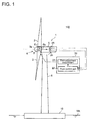
- FIG. 1 is a diagram of an overall configuration of a wind turbine power generating apparatus according to one embodiment.
- a floating-body wind turbine power generating apparatus 100 includes a wind turbine generator 1, a floating body 10 on which the wind turbine generator 1 is built, and a control device 20 for controlling the wind turbine generator 1.
- the wind turbine generator 1 includes a rotor 4 including at least one blade 2 and a hub 3, a nacelle 5 rotatably supporting the rotor 4, and a tower 6 supporting the nacelle 5.
- the hub 3 may be covered by a hub cover 3a.
- the rotor 4 may be coupled to a generator via a drivetrain (not illustrated).
- the drivetrain may include a main shaft coupled to the hub 3 and a speed increasing unit (e.g. a hydraulic transmission or a gearbox) for increasing rotational speed of the main shaft and inputting the rotation to a generator.
- a speed increasing unit e.g. a hydraulic transmission or a gearbox
- a generator may be directly connected to the hub 3 of the rotor 4.
- the blade 2 receives wind and the rotor 4 rotates so that electric power is generated in the generator.
- the floating-body wind turbine power generating apparatus 100 may include various sensors such as an acceleration sensor 25 and an attitude detection sensor 26 mounted to the hub 3, the nacelle 5, or an upper part of the tower 6.
- the nacelle 5 may be capable of yaw rotating with respect to the tower 6.
- the wind turbine generator 1 is an upwind wind turbine configured such that the nacelle 5 yaw rotates so that the blade 2 is oriented toward the upwind side in accordance with the wind direction during normal operation.
- the floating body 10 has buoyance, and floats on the water.
- the floating body 10 is connected to an anchor by a mooring line to be moored on a predetermined position on the water.
- the tower 6 is disposed on the floating body 10.
- various floating bodies can be employed, such as a semi-sub type and a spar type.
- the control device 20 includes a pitch adjustment mechanism 21 for adjusting a pitch angle of the blade 2, and a pitch control part 22 for controlling the pitch adjustment mechanism 21.
- the control device 20 receives signals inputted from the various sensors such as the acceleration sensor 25 and the attitude detection sensor 26.
- a pitch control may be performed on the blade 2 on the basis of inclination motion information or attitude information of the wind turbine generator 1 obtained from the above signals.
- the pitch adjustment mechanism 21 may be disposed in the hub 3 and for each of the at least one blade 2. For instance, in a case where three blades 2 are provided, three pitch adjustment mechanisms 21 are provided. Each pitch adjustment mechanism 21 may individually adjust the pitch angle of the corresponding blade 2, or adjust the pitch angles of the entire blades 2 in cooperation.
- the pitch control part 22 controls the pitch adjustment mechanism 21 so that an aerodynamic braking force is applied to the rotor 4 due to an increase in the pitch angle upon stoppage of the wind turbine generator. Further, the pitch control part 22 controls the pitch angle of the blade 2 to decrease so that a lift applied to the blade 2 increases, upon start of the wind turbine generator.
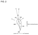
- each blade 2 has an airfoil in which a pressure surface 203 and a suction surface 204 extend from a leading edge 201 to a trailing edge 202.
- a straight line 205 connecting the leading edge 201 and the trailing edge 202 is referred to as a chord.
- Each blade 2 is oriented so that the chord 205 forms an angle "a" from the rotational direction of the rotor, by the pitch adjustment mechanism 21 operating under control of the pitch control part 22.
- This angle “a” is an angle between the extended line L 1 of the chord 205 and the straight line L 2 parallel to the rotational direction of the blade (the rotational plane of the rotor), indicating the pitch angle of the blade 2.
- the pitch angle "a” of each blade 2 during normal operation of the wind turbine generator 1 is approximately zero degree, and this pitch angle is sometimes referred to as a fine position.
- the pitch angle "a" of each blade 2 during complete stoppage of the wind turbine generator 1 is approximately 90 degrees (the maximum angle), and this pitch angle is sometimes referred to as a feather position.
- a rotor of a wind turbine generator moves back and forth to a certain extent in accordance with vibration of a tower.
- the cycle of the vibration of the tower in this case is short enough as compared to the time the influence of the change in the pitch angle due to rotation of the blade by the pitch adjustment mechanism requires to substantially appear as a change in the thrust force.
- the influence is barely recognizable in the vibration of the tower.
- the sway cycle of a floating body is approximately 10 seconds.
- the influence of varying the pitch angle by rotating the blade 2 with the pitch adjustment mechanism 21 can substantially appear as a change in the thrust force.
- a thrust force received by the rotor 4 from wind is varied by the pitch control, sway of the floating body 10 would be also affected.
- the pitch control is performed upon stoppage and start of the wind turbine generator 1 taking account of the above relationship between the sway of the floating body 10 and the aerodynamic thrust force received by the rotor 4.
- pitch control for the blade 2 performed by the pitch control part 22 upon stoppage and start of the wind turbine generator 1 illustrated in FIG. 1 .
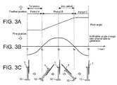
- FIGs. 3A to 3C are diagrams for describing a pitch control upon stoppage of a wind turbine generator according to an embodiment of the present embodiment, illustrating a temporal change of the pitch angle, a temporal change of an inclination angle change rate of the wind turbine generator, and a motion of the wind turbine generator, respectively.
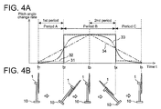
- FIGs. 4A and 4B are diagrams for describing a pitch control upon stoppage of a wind turbine generator according to an embodiment of the present embodiment, illustrating a pitch angle change rate of the wind turbine generator and a motion of the wind turbine generator, respectively.
- FIG. 5 is a flowchart for describing a pitch control upon stoppage of a wind turbine generator according to an embodiment of the present embodiment.
- reference signs for the components in the following description are identical to those of the floating-body wind turbine power generating apparatus 100 illustrated in FIG. 1 .
- FIGs. 3C and 4B sway of the floating body 10 inclines the wind turbine generator 1 back and forth (toward the upwind side and the downwind side).
- the back-and-forth inclination motion of the wind turbine generator 1 is repeated, but only one section (one cycle) corresponding to one back-and-forth inclination motion of the repeated motion is extracted and illustrated in FIGs. 3A to 4B .
- the drawings illustrate: time t 1 when the wind turbine generator 1 is in the vertical direction (hereinafter, referred to as the vertical attitude); time t 2 when the wind turbine generator 1 is in the foremost inclined attitude as a result of the inclining motion to the upwind side; time t 3 when the wind turbine generator 1 returns to the vertical attitude due to the inclining motion toward the downwind side; time t 4 when the wind turbine generator 1 is in the rearmost inclined attitude as a result of the inclining motion to the downwind side; and time t 5 when the wind turbine generator 1 returns to the vertical attitude as a result of the inclining motion toward the upwind side.
- FIG. 3B illustrates a temporal change of the inclination angle change rate of the wind turbine generator 1 corresponding to the above inclining motion.
- the inclination angle change rate (inclination velocity) toward the upwind side of the wind turbine generator 1 is indicated as negative, and the inclination angle change rate (inclination velocity) toward the downwind side is indicated as positive.
- the inclination angle change rate of the wind turbine generator 1 reaches its minimum at time t 1 , when the wind turbine generator 1 is inclining from the downwind side toward the upwind side and in the vertical attitude, and becomes zero at time t 2 , when the wind turbine generator 1 is in the foremost inclined attitude.
- the inclination angle change rate reaches it maximum at time t 3 , when the wind turbine generator 1 is inclining from the forward inclined attitude to the downwind side and in the vertical attitude, and becomes zero at time t 4 when the wind turbine generator 1 is in the rearmost inclined attitude.
- FIG. 3A illustrates a temporal change of the pitch angle of the blade 2 of the wind turbine generator 1.
- the pitch control part 22 calculates a command value of the pitch angle change rate (pitch rate) of the blade 2 and provides the command value to the pitch adjustment mechanism 21 until the pitch angle of the blade 2 reaches a target pitch angle (e.g. maximum angle), when the pitch angle of the blade 2 is increased.
- FIG. 4A illustrates pitch angle change rate curves, each of which is time-series data of a command value given to the pitch adjustment mechanism 21. In the drawing, four types of pitch angle change rate curves 31 to 34 are illustrated. The pitch angle change rate curve 31 indicated by a solid line corresponds to the pitch angle of FIG. 3A .
- the thrust force received by the rotor 4 from wind is a factor that reduces the acceleration of the wind turbine generator 1 toward the upwind side, and functions advantageously in restriction of sway of the floating body 10.
- a rapid increase in the pitch angle of the blade 2 during the first period means a decrease in the factor for reducing the acceleration of the wind turbine generator 1 toward the upwind side, which may possibly amplify the sway of the floating body 10.
- the thrust force received by the rotor 4 from wind is a factor that increases the acceleration of the wind turbine generator 1 toward the downwind side, and functions disadvantageously in restriction of sway of the floating body 10.
- a rapid increase in the pitch angle of the blade 2 during the second period means a decrease in the factor for increasing the acceleration of the wind turbine generator 1 toward the downwind side, which may possibly contribute to restriction of the sway of the floating body.
- the following pitch control is performed in view of the above relationship between sway of the floating body 10 and the aerodynamic thrust force received by the rotor 4.
- the pitch control part 22 increases the pitch angle of the blade 2 so that the first change rate (increasing speed) of the pitch angle of the blade 2 in the first period, during which the wind turbine generator 1 is in an inclining motion toward the upwind side from the vertical direction, is smaller than the second change rate (increasing speed) of the pitch angle of the blade 2 in the second period, during which the wind turbine generator 1 is in an inclining motion toward the downwind side from the vertical direction.
- the pitch angle is changed in accordance with the pitch angle change rate curve 31.
- the pitch angle change rate is set to zero in the first period from time t 1 to time t 2 so as to keep the pitch angle constant, and the pitch angle change rate is set to a value greater than zero in the second period from time t 3 to time t 4 so as to increase the pitch angle at a constant rate.
- the first change rate (increasing speed) of the pitch angle in the first period being smaller than the second change rate (increasing speed) of the pitch angle in the second period, it is possible to restrict a decrease in the aerodynamic thrust force of the first period, which functions advantageously in restriction of the sway of the floating body, as well as to promote a decrease in the aerodynamic thrust force in the second period, which functions disadvantageously in restriction of the sway of the floating body.
- the pitch control part 22 may control the pitch adjustment mechanism 21 to increase the pitch angle of the blade 2 so that the change rate of the pitch angle of the blade 2 in the total period (period A) during which the wind turbine generator 1 is in an inclining motion toward the upwind side, is smaller than the change rate of the pitch angle of the blade 2 in the total period (period B) during which the wind turbine generator 1 is in an inclining motion toward the downwind side.
- the pitch angle is changed in accordance with the pitch angle change rate curve 31.
- the pitch angle change rate is set to zero in the period A from time t 1 to time t 2 and time t 4 to time t 5 , and the pitch angle change rate is set to a value greater than zero in the period B from time t 2 to time t 4 .
- the thrust force received by the rotor 4 from wind contributes to restriction of the inclining motion of the wind turbine generator 1 toward the upwind side associated with the sway of the floating body 10.
- the thrust force received by the rotor 4 from wind promotes the inclining motion of the wind turbine generator 1 toward the downwind side associated with the sway of the floating body 10.
- the pitch angle change rate is varied in a stepped pattern between the pitch angle change rate V A of the period A and the pitch angle change rate V B (>V A ) of the period B.
- the pitch angle change rate is varied in a stepped pattern between the pitch angle change rate V A of the period A, which is greater than zero, and the pitch angle change rate V B (>V A ) of the period B.
- At least one of the pitch angle change rate V A of the period A including the first period or the pitch angle change rate V B of the period B including the second period may be set on the basis of an optional function F (t). That is, the pitch angle change rate V A or the pitch angle change rate V B may be varied continuously with time.
- the pitch angle change rate upon transition from the first period to the second period, is monotonically increased from the first change rate to the second change rate. Also, upon transition from the second period to the first period, the pitch angle change rate is monotonically decreased from the second change rate to the first change rate.
- the pitch angle change rate is monotonically increased from the first change rate to the second change rate, and upon transition from the second period to the first period, the pitch angle change rate is monotonically decreased from the second change rate to the first change rate, which makes it possible to smoothly stop the wind turbine generator 1 by the pitch control.
- the pitch angle change rate may be increased or decreased in a stepped pattern as indicated by the above pitch angle change rate curves 31, 32.
- the pitch angle change rate may be increased or decreased gradually between the first period and the second period as indicated by the pitch angle change rate curves 33, 34.
- the pitch angle change rate may be increased in a stepped pattern at time t 2 , when the wind turbine generator 1 is in the foremost inclined attitude, and the pitch angle change rate may be decreased in a stepper pattern at time t 4 , when the wind turbine generator 1 is inclined to the rearmost inclined attitude, in accordance with the pitch angle change rate curves 31, 32.
- the pitch angle change rate may be increased linearly from time t 1 , when the wind turbine generator 1 is in the vertical attitude, to time t 3 , when the wind turbine generator 1 has inclined toward the front (upwind side) to return to the vertical attitude, and may be decreased linearly from time t 3 to time t 5 , when the wind turbine generator 1 has inclined to the rear (downwind side) to return to the vertical attitude.
- the pitch angle change rate may be increased in a curve from time t 1 , when the wind turbine generator 1 is in the vertical attitude, to time t 3 , when the wind turbine generator 1 has inclined toward the front (upwind side) to return to the vertical attitude, and may be decreased in a curve from time t 3 to time t 5 , when the wind turbine generator 1 has inclined to the rear (downwind side) to return to the vertical attitude.
- the inclining motion information may be an inclination angle change rate or an inclining direction of the wind turbine generator 1. Further, the inclination angle change rate or the inclining direction may be obtained from various sensors such as the acceleration sensor 25 and the attitude detection sensor.
- the pitch angle change rate V A is set (S14). If the period corresponding to the current motion of the wind turbine generator 1 is not the period A, the period is determined to be the period B, and the pitch angle change rate V B is set (S 15). At this time, the pitch angle change rate V A is smaller than the pitch angle change rate V B .
- the pitch angle change rate V A or the pitch angle change rate V B having been set is inputted to the pitch adjustment mechanism 21 as a command value, and the pitch adjustment mechanism 21 increases the pitch angle of the blade 2 (S16).
- a target pitch angle e.g. the maximum angle
- the pitch control part 22 determines whether the pitch angle of the blade 2 has reached the target pitch angle (S 17). If the target pitch angle is reached, the pitch control is completed.
- FIGs. 6A to 6C are diagrams for describing a pitch control upon stoppage of a wind turbine generator according to another embodiment of the present embodiment, illustrating a temporal change of the pitch angle, a temporal change of an inclination angle of the wind turbine generator, and a motion of the wind turbine generator, respectively.
- FIGs. 7A to 7C are diagrams for describing a pitch control upon stoppage of a wind turbine generator according to another embodiment of the present embodiment, illustrating a pitch angle change rate curve of the wind turbine generator, a motion of the wind turbine generator, and a variation example of a pitch angle change rate of the wind turbine generator, respectively.
- FIG. 8 is a flowchart for describing a pitch control upon stoppage of a wind turbine generator according to another embodiment of the present embodiment.
- the time (t 1 to t 5 ) and the first and second periods illustrated in FIGs. 6A to 7C correspond to those in the above described FIGs. 3A to 4B .
- the inclination angle of the wind turbine generator 1 caused by sway of the floating body 10 transitions as described below. That is, the inclination angle of the wind turbine generator 1 becomes zero at time t 1 , when the wind turbine generator 1 is in an inclining motion from the downwind side toward the upwind side and in the vertical attitude, and reaches its minimum at time t 2 , when the wind turbine generator 1 is in the foremost inclined attitude. Further, the inclination angle becomes zero at time t 3 , when the wind turbine generator 1 is in an inclining motion from the upwind side toward the downwind side and in the vertical attitude, and reaches its maximum at time t 4 , when the wind turbine generator 1 is in the rearmost inclined attitude.
- the inclination angle toward the upwind side of the wind turbine generator 1 is indicated as negative, and the inclination toward the downwind side as positive.
- the pitch control part 22 calculates a command value of the pitch angle change rate (pitch rate) of the blade 2 and provides the command value to the pitch adjustment mechanism 21 until the pitch angle of the blade 2 reaches a target pitch angle (e.g. maximum angle), when the pitch angle of the blade 2 is increased.
- FIG. 7A illustrates pitch angle change rate curves, each of which is time-series data of a command value given to the pitch adjustment mechanism 21. In the drawing, four patterns of pitch angle change rate curves 35 to 38 are illustrated. The pitch angle change rate curve 35 indicated by a solid line corresponds to the pitch angle of FIG. 6A .
- the pitch control part 22 may control the pitch adjustment mechanism 21 to increase the pitch angle of the blade 2 so that the change rate of the pitch angle of the blade 2 in the total period during which the wind turbine generator 1 is in an inclined attitude toward the upwind side is smaller than the change rate of the pitch angle of the blade 2 in the total period during which the wind turbine generator 1 is in an inclined attitude toward the downwind side.
- the pitch angle change rate is set to zero in the period C from time t 1 to time t 3 in accordance with the pitch angle change rate curve 35 so as to keep the pitch angle constant
- the pitch angle change rate is set to a value greater than zero in the period D from time t 3 to time t 5 in accordance with the pitch angle change rate curve 35, so as to increase the pitch angle at a constant rate.
- the attitude of the wind turbine generator 1 In the floating-body wind turbine power generating apparatus 100, it is desirable to maintain the attitude of the wind turbine generator 1 to be as vertical as possible.
- the pitch control when the wind turbine generator is stopped by the pitch control, it is possible to promote a motion of the wind turbine generator 1 for returning to the vertical attitude, if the attitude of the wind turbine generator 1 is taken into account and the change rate (increasing speed) of the pitch angle is reduced in the total period during which the wind turbine generator 1 is in an inclined attitude toward the upwind side as compared to that in the total period during which the wind turbine generator 1 is in an inclined attitude toward the downwind side.
- the pitch angle change rate in the period C is set to zero to maintain the pitch angle to be constant, and the pitch angle change rate in the period D is set to a value larger than zero to increase the pitch angle at a constant rate.
- the pitch angle change rate curve 36 in FIG. 7A the pitch angle change rate in the period C may be larger than zero and smaller than the pitch angle change rate in the period D.
- the pitch angle change rate curves 37, 38 at least one of the pitch angle change rates in the period C or the period D may be varied with time.
- the pitch angle change rate may be monotonically increased from the first change rate to the second change rate. Also, upon transition from the second period to the first period, the pitch angle change rate may be monotonically decreased from the second change rate to the first change rate.
- the pitch angle change rate may be increased or decreased in a stepped pattern as indicated by the above pitch angle change rate curves 35, 36.
- the pitch angle change rate may be increased or decreased gradually between the first period and the second period as indicated by the pitch angle change rate curves 37, 38.
- the pitch angle change rate may be decreased in a stepped pattern at time t 1 , when the wind turbine generator 1 is in the vertical attitude immediately before inclining forward (to the upwind side), and the pitch angle change rate may be increased in a stepper pattern at time t 3 , when the wind turbine generator 1 has inclined to the front to return to the vertical attitude, in accordance with the pitch angle change rate curves 35, 36.
- the pitch angle change rate may be increased linearly from time t 2 , when the wind turbine generator 1 is in the foremost inclined attitude to time t 4 , when the wind turbine generator 1 has inclined to the rear (downwind side) to take the rearmost inclined attitude, and may be decreased linearly from time t 4 to the time when the wind turbine generator 1 has inclined to the front to take the foremost inclined attitude.
- the pitch angle change rate may be increased in a curve from time t 2 , when the wind turbine generator 1 is in the foremost inclined attitude to time t 4 , when the wind turbine generator 1 has inclined to the rear (downwind side) to take the rearmost inclined attitude, and may be decreased in a curve from time t 4 to the time when the wind turbine generator 1 has inclined to the front (upwind side) to take the foremost inclined attitude.
- the pitch control of the blade 2 may be performed in accordance with the pitch angle change rate curves 35', 37', 38', which are offset from the pitch angle change rate curves 35, 37, 38 in FIG. 7A toward the upstream side with respect to time.
- the amount by which each of the pitch angle change rate curves 35, 37, 38 is offset is not particularly limited as long as it is within a range where the pitch angle change rate in the first period is smaller than the pitch angle change rate in the second period.
- attitude information of the wind turbine generator 1 is obtained (S22).
- the attitude information may be an inclination angle of the wind turbine generator 1.
- the inclination angle may be obtained from various sensors such as the acceleration sensor 25 and the attitude detection sensor.
- the pitch angle change rate V C is set (S24). If the period corresponding to the current motion of the wind turbine generator 1 is not the period C, the period is determined to be the period D, and the pitch angle change rate V D is set (S25). At this time, the pitch angle change rate V C is smaller than the pitch angle change rate V D .
- the pitch angle change rate V C or the pitch angle change rate V D having been set is inputted to the pitch adjustment mechanism 21 as a command value, and the pitch adjustment mechanism 21 increases the pitch angle of the blade 2 (S26).
- a target pitch angle e.g. the maximum angle
- the pitch control part 22 determines whether the pitch angle of the blade 2 has reached the target pitch angle (S27). If the target pitch angle is reached, the pitch control is completed.
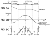
- FIGs. 9A to 9C are diagrams for describing a pitch control upon start of a wind turbine generator according to an embodiment of the present embodiment, illustrating a temporal change of the pitch angle, a temporal change of the inclination angle change rate of the wind turbine generator, and a motion of the wind turbine generator, respectively.
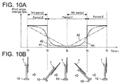
- FIGs. 10A and 10B are diagrams for describing a pitch control upon start of a wind turbine generator according to an embodiment of the present embodiment, illustrating a pitch angle change rate of the wind turbine generator and a motion of the wind turbine generator, respectively.
- FIG. 11 is a flowchart for describing a pitch control upon start of a wind turbine generator 1 according to an embodiment of the present embodiment.
- FIG. 9A illustrates a temporal change of the pitch angle of the blade 2 of the wind turbine generator 1.
- the pitch control part 22 calculates a command value of the pitch angle change rate (pitch rate) of the blade 2 and provides the command value to the pitch adjustment mechanism 21 until the pitch angle of the blade 2 reaches a target pitch angle (e.g. zero degree), when the pitch angle of the blade 2 is decreased.
- FIG. 10A illustrates pitch angle change rate curves, each of which is time-series data of a command value given to the pitch adjustment mechanism 21. In the drawing, four types of pitch angle change rate curves 41 to 44 are illustrated. The pitch angle change rate curve 41 indicated by a solid line corresponds to the pitch angle of FIG. 9A .
- the thrust force received by the rotor 4 from wind is a factor that reduces the acceleration of the wind turbine generator 1 toward the upwind side, and functions advantageously in restriction of sway of the floating body 10.
- a rapid decrease in the pitch angle of the blade 2 during the third period means an increase in the factor for reducing the acceleration of the wind turbine generator 1 toward the upwind side, which may possibly contribute to restriction of the sway of the floating body 10.
- the thrust force received by the rotor 4 from wind is a factor that increases the acceleration of the wind turbine generator 1 toward the downwind side, and functions disadvantageously in restriction of sway of the floating body 10.
- a rapid decrease in the pitch angle of the blade 2 during the fourth period means an increase in the factor for increasing the acceleration of the wind turbine generator 1 toward the downwind side, which may amplify the sway of the floating body 10.
- the following pitch control is performed in view of the above relationship between sway of the floating body 10 and the aerodynamic thrust force received by the rotor 4.
- the pitch control part 22 decreases the pitch angle of the blade 2 so that the third change rate (decreasing speed) of the pitch angle of the blade 2 in the third period, during which the wind turbine generator 1 is in an inclining motion toward the upwind side from the vertical direction, is larger than the fourth change rate (decreasing speed) of the pitch angle of the blade 2 in the fourth period, during which the wind turbine generator 1 is in an inclining motion toward the downwind side from the vertical direction.
- the pitch angle is changed in accordance with the pitch angle change rate curve 41.
- the pitch angle change rate is set to a value larger than zero in the third period from time t 1 to time t 2 so as to increase the pitch angle at a constant rate, and the pitch angle change rate is set to zero in the fourth period from time t 3 to time t 4 so as to keep the pitch angle constant.
- the third change rate (decreasing speed) of the pitch angle in the third period being larger than the fourth change rate (decreasing speed) of the pitch angle in the fourth period, it is possible to promote an increase in the aerodynamic thrust force of the third period, which functions advantageously in restriction of the sway of the floating body, as well as to restrict an increase in the aerodynamic thrust force of the fourth period, which functions disadvantageously in restriction of the sway of the floating body.
- the pitch control part 22 may control the pitch adjustment mechanism 21 to decrease the pitch angle of the blade 2 so that the change rate of the pitch angle of the blade 2 in the total period (period E) during which the wind turbine generator 1 is in an inclining motion toward the upwind side, is larger than the change rate of the pitch angle of the blade 2 in the total period (period F) during which the wind turbine generator 1 is in an inclining motion toward the downwind side.
- the pitch angle is changed in accordance with the pitch angle change rate curve 41.
- the pitch angle change rate is set to a value greater than zero in the period E from time t 1 to time t 2 and time t 4 to t 5 , and the pitch angle change rate is set to zero in the period F from time t 2 to time t 4 .
- the thrust force received by the rotor 4 from wind contributes to restriction of the inclining motion of the wind turbine generator 1 toward the upwind side associated with the sway of the floating body 10.
- the thrust force received by the rotor 4 from wind promotes the inclining motion of the wind turbine generator 1 toward the downwind side associated with the sway of the floating body 10.
- the pitch angle change rate is varied in a stepped pattern between the pitch angle change rate V E of the period E and the pitch angle change rate V F ( ⁇ V E ) of the period F.
- the pitch angle change rate is varied in a stepped pattern between the pitch angle change rate V E of the period E and the pitch angle change rate V F ( ⁇ V E ) of the period F, which is greater than zero.
- At least one of the pitch angle change rate V E of the period E including the third period or the pitch angle change rate V F of the period F including the fourth period may be set on the basis of an optional function F (t). That is, the pitch angle change rate V E or the pitch angle change rate V F may be varied continuously with time.
- the pitch angle change rate upon transition from the third period to the fourth period, is monotonically decreased from the third change rate to the fourth change rate. Also, upon transition from the fourth period to the third period, the pitch angle change rate is monotonically increased from the fourth change rate to the third change rate.
- the pitch angle change rate is monotonically decreased from the third change rate to the fourth change rate. Also, upon transition from the fourth period to the third period, the pitch angle change rate is monotonically increased from the fourth change rate to the third change rate, which makes it possible to smoothly start the wind turbine generator 1 by the pitch control.
- the pitch angle change rate may be increased or decreased in a stepped pattern as indicated by above the pitch angle change rate curves 41, 42.
- the pitch angle change rate may be increased or decreased gradually between the third period and the fourth period as indicated by the pitch angle change rate curves 43, 44.
- the pitch angle change rate may be decreased in a stepped pattern at time t 2 , when the wind turbine generator 1 is in the foremost inclined attitude, and the pitch angle change rate may be increased in a stepped pattern at time t 4 , when the wind turbine generator 1 is in the rearmost inclined attitude, in accordance with the pitch angle change rate curves 41, 42.
- the pitch angle change rate may be decreased linearly from time t 1 , when the wind turbine generator 1 is in the vertical attitude to time t 3 , when the wind turbine generator 1 has inclined toward the front (upwind side) to return to the vertical attitude, and the pitch angle change rate may be increased linearly from time t 3 to time t 5 , when the wind turbine generator 1 has inclined to the rear (downwind side) to return to the vertical attitude.
- the pitch angle change rate may be decreased in a curve from time t 1 , when the wind turbine generator 1 is in the vertical attitude to time t 3 , when the wind turbine generator 1 has inclined toward the front (upwind side) to return to the vertical attitude, and may be increased in a curve from time t 3 to time t 5 , when the wind turbine generator 1 has inclined to the rear (downwind side) to return to the vertical attitude.
- the inclining motion information may be an inclination angle change rate or an inclining direction of the wind turbine generator 1. Further, the inclination angle change rate or the inclining direction may be obtained from various sensors such as the acceleration sensor 25 and the attitude detection sensor.
- a period corresponding to the current motion of the wind turbine generator 1 matches the period E in which the wind turbine generator 1 is inclining toward the upwind side (S33). If the period corresponding to the current motion of the wind turbine generator 1 is the period E, the pitch angle change rate V E is set (S34). If the period corresponding to the current motion of the wind turbine generator 1 is not the period E, the period is determined to be the period F, and the pitch angle change rate V F is set (S35). At this time, the pitch angle change rate V E is smaller than the pitch angle change rate V F .
- the pitch angle change rate V E or the pitch angle change rate V F having been set is inputted to the pitch adjustment mechanism 21 as a command value, and the pitch adjustment mechanism 21 decreases the pitch angle of the blade 2 (S36).
- a target pitch angle e.g. zero degree
- the pitch control part 22 determines whether the pitch angle of the blade 2 has reached the target pitch angle (S37). If the target pitch angle is reached, the pitch control is completed.
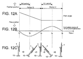
- FIGs. 12A to 12C are diagrams for describing a pitch control upon start of a wind turbine generator according to another embodiment of the present embodiment, illustrating a temporal change of the pitch angle, a temporal change of an inclination angle of the wind turbine generator, and a motion of the wind turbine generator, respectively.
- FIGs. 13A and 13B are diagrams for describing a pitch control upon start of a wind turbine generator according to an embodiment of the present embodiment, illustrating a pitch angle change rate of the wind turbine generator and a motion of the wind turbine generator, respectively.
- FIG. 14 is a flowchart for describing a pitch control upon start of a wind turbine generator according to another embodiment of the present embodiment.
- the time (t 1 to t 5 ) and the third and fourth periods illustrated in FIGs. 12A to 13B correspond to those in the above described FIGs. 9A to 10B .
- the pitch control part 22 calculates a command value of the pitch angle change rate (pitch rate) of the blade 2 and provides the command value to the pitch adjustment mechanism 21 until the pitch angle of the blade 2 reaches a target pitch angle (e.g. zero degree), when the pitch angle of the blade 2 is decreased.
- FIG. 13A illustrates pitch angle change rate curves, each of which is time-series data of a command value given to the pitch adjustment mechanism 21. In the drawing, four patterns of pitch angle change rate curves 45 to 48 are illustrated. The pitch angle change rate curve 45 indicated by a solid line corresponds to the pitch angle of FIG. 12A .
- the pitch control part 22 may control the pitch adjustment mechanism 21 to decrease the pitch angle of the blade 2 so that the change rate of the pitch angle of the blade 2 in the total period during which the wind turbine generator 1 is in an inclined attitude toward the upwind side is larger than the change rate of the pitch angle of the blade 2 in the total period during which the wind turbine generator 1 is in an inclined attitude toward the downwind side.
- the pitch angle change rate is set to a value larger than zero in the period G from time t 1 to time t 3 so as to decrease the pitch angle at a constant rate in accordance with the pitch angle change rate curve 45, and the pitch angle change rate is set to zero in the period H from time t 3 to time t 5 in accordance with the pitch angle change rate curve 45, so as to maintain the pitch angle constant.
- the attitude of the wind turbine generator 1 In the floating-body wind turbine power generating apparatus 100, it is desirable to maintain the attitude of the wind turbine generator 1 to be as vertical as possible.
- the pitch control when the wind turbine generator 1 is started by the pitch control, it is possible to promote a motion of the wind turbine generator 1 for returning to the vertical attitude, if the attitude of the wind turbine generator 1 is taken into account and the change rate (decreasing speed) of the pitch angle is increased in the total period during which the wind turbine generator 1 is in an inclined attitude toward the upwind side as compared to that in the total period during which the wind turbine generator 1 is in an inclined attitude toward the downwind side.
- the pitch angle change rate in the period G is set to a value larger than zero to decrease the pitch angle at a constant rate
- the pitch angle change rate in the period H is set to zero to maintain the pitch angle to be constant.
- the pitch angle change rate in the period H may be larger than zero and smaller than the pitch angle change rate in the period G.
- the pitch angle change rate curves 47, 48 at least one of the pitch angle change rates in the period C or the period D may be varied with time.
- the pitch angle change rate may be monotonically decreased from the third change rate to the fourth change rate. Also, upon transition from the fourth period to the third period, the pitch angle change rate may be monotonically increased from the fourth change rate to the third change rate.
- the pitch angle change rate may be increased or decreased in a stepped pattern as indicated by the above pitch angle change rate curves 45, 46 or the pitch angle change rate may be increased or decreased gradually between the third period and the fourth period as indicated by the pitch angle change rate curves 47, 48.
- the pitch angle change rate may be increased in a stepped pattern at time t 1 , when the wind turbine generator 1 is in the vertical attitude immediately before inclining forward (to the upwind side), and the pitch angle change rate may be decreased in a stepper pattern at time t 3 , when the wind turbine generator 1 has inclined toward the front to return to the vertical attitude, in accordance with the pitch angle change rate curves 45, 46.
- the pitch angle change rate may be decreased linearly from time t 2 , when the wind turbine generator 1 is in the foremost inclined attitude, to time t 4 , when the wind turbine generator 1 has inclined toward the rear (downwind side) to take the rearmost inclined attitude, and the pitch angle change rate may be increased linearly from time t 4 to the time when the wind turbine generator 1 has inclined toward the front to take the foremost inclined attitude.
- the pitch angle change rate may be decreased in a curve from time t 2 , when the wind turbine generator 1 is in the foremost inclined attitude, to time t 4 , when the wind turbine generator 1 has inclined to the rear (downwind side) to take the rearmost inclined attitude, and may be increased in a curve from time t 4 to the time when the wind turbine generator 1 has inclined to the front to take the foremost inclined attitude.
- the pitch control of the blade 2 may be performed in accordance with pitch angle change rate curves offset from the pitch angle change rate curves 45, 46, 47, 48 in FIG. 13A toward the upstream side with respect to time.
- the amount by which each of the pitch angle change rate curves 45, 46, 47, 48 is offset is not particularly limited as long as it is within a range where the pitch angle change rate in the third period is larger than the pitch angle change rate in the fourth period.
- attitude information of the wind turbine generator 1 is obtained (S42).
- the attitude information may be an inclination angle of the wind turbine generator 1.
- the inclination angle may be obtained from various sensors such as the acceleration sensor 25 and the attitude detection sensor.
- the pitch angle change rate V G is set (S44). If the period corresponding to the current motion of the wind turbine generator 1 is not the period G, the period is determined to be the period H, and the pitch angle change rate V H is set (S45). At this time, the pitch angle change rate V G is larger than the pitch angle change rate V H .
- the pitch angle change rate V G or the pitch angle change rate V H having been set is inputted to the pitch adjustment mechanism 21 as a command value, and the pitch adjustment mechanism 21 decreases the pitch angle of the blade 2 (S46).
- a target pitch angle e.g. zero degree
- the pitch control part 22 determines whether the pitch angle of the blade 2 has reached the target pitch angle (S47). If the target pitch angle is reached, the pitch control is completed.
- the respective pitch angle change rates may be varied between the plurality of blades 2 until the target pitch angle is achieved, so that a moment acting as a restoration force against the sway of the floating body 10 is obtained.
- the pitch angle change rates are varied in accordance with the respective angular positions of the blades in the rotor rotational plane.
- the pitch angle change rate of one of the blades 2 positioned at the upper part of the rotor rotational plane is set to be smaller than the pitch angle change rate of one of the blades 2 positioned at the lower part of the rotor rotational plane.
- the pitch angle change rate of one of the blades 2 positioned at the lower part of the rotor rotational plane is set to be smaller than the pitch angle change rate of one of the blades positioned at the upper part of the rotor rotational plane, which makes it possible to contribute to restriction of the sway of the floating body 10.
- the wind turbine generator 1 is started, it is also possible to restrict the sway of the floating body 10 by controlling the respective pitch angle change rates of the plurality of the blades 2 individually in a suitable manner.
- the respective pitch angle change rates may be varied by differentiating the phases of the blades 2 on the pitch angle change rate curve in FIG. 4 , or the respective pitch adjustment mechanism 21 of the blades 2 may be provided with different pitch angle change rate curves.
- the yaw control for the wind turbine generator 1 may be used in cooperation with the above pitch control to assist the deceleration of the rotor 4.
- the wind turbine generator 1 includes a yaw drive mechanism for rotating the nacelle 5 in the horizontal direction with respect to the tower 6, and a yaw control part for controlling the yaw driving mechanism.
- the yaw control part controls the yaw drive mechanism so that the rotor 4 faces the downwind side, at the same time as the pitch control, or before or after the pitch control. In this way, it is possible to stop the wind turbine generator 1 swiftly.
- the present invention can be applied to a floating-body wind turbine power generating apparatus of a downwind type.
- the pitch angle change rate (increasing speed or decreasing speed of the pitch angle) is determined on the basis of the inclination angle or the inclination angle change rate of the wind turbine generator 1 when the wind turbine generator 1 is stopped or started.
- the pitch angle change rate may be determined on the basis of both of the inclination angle and the inclination angle change rate of the wind turbine generator 1.
- the pitch angle change rate (increasing speed or decreasing speed of the pitch angle) may be determined using other indexes such as a rotation speed of the rotor 4, a current pitch angle, and an elapsed time after start of the pitch control.
Landscapes
- Engineering & Computer Science (AREA)
- Life Sciences & Earth Sciences (AREA)
- Sustainable Development (AREA)
- Sustainable Energy (AREA)
- Chemical & Material Sciences (AREA)
- Combustion & Propulsion (AREA)
- Mechanical Engineering (AREA)
- General Engineering & Computer Science (AREA)
- Physics & Mathematics (AREA)
- Fluid Mechanics (AREA)
- Wind Motors (AREA)
Description
- The present disclosure relates to a method and device for controlling a floating-body wind turbine power generating apparatus including a wind turbine generator disposed on a floating body, and a floating-body wind turbine power generating apparatus.
- Wind turbine power generating apparatuses have become increasingly popular in recent years in view of preservation of the global environment. In a typical wind turbine power generating apparatus, pitch angles of blades are variable, and a pitch control is performed in accordance with the operation state of the wind turbine power generating apparatus.
- For instance, although not related to a floating-body wind turbine power generating apparatus,
Patent Documents 1 to 3 disclose a pitch-control method whereby a load applied to a wind turbine power generating apparatus is reduced. Further,Non-patent Document 1 discloses a method of controlling the pitch of each blade individually so as to reduce an ultimate load of a wind turbine power generating apparatus upon occurrence of gust or shutdown of the system (p. 126-127). -
- Patent Document 1:
US Patent No. 8215896 - Patent Document 2:
US Patent No. 8240990 - Patent Document 3: Japanese Unexamined Patent Application (PCT Translation) Publication No.
2009-523208 - Besides,
US 2011/0140420 discloses a method and a device according respectively to the preamble of theclaims 1 and 9 and of theclaims - Non-patent Document 1: E.Bossanyi, B.Savini, M.Iribas, M.Hau, B.Fischer, D.Schlipf, T.van Engelen, M.Rossetti and C.E.Carcangiu "Advanced controller reserch for multi-MW wind turbines in the UPWIND project", Wind Energ.2012;15:119-145
- Meanwhile, in a floating-body wind turbine power generating apparatus, there is a close mutual relationship between sway of a floating body and an aerodynamic load of a thrust component (a thrust force) received by a rotor.
- That is, a thrust force received by the rotor from wind is affected by sway of a floating body, because a wind turbine generator (rotor) moves back and forth due to the sway of the floating body. For instance, while the floating-body wind turbine power generating apparatus inclines toward the upwind side due to sway of the floating body, a relative wind velocity with respect to the rotor is a sum of an actual wind velocity and a moving velocity of the wind turbine generator (rotor) moving toward the upwind side, so the thrust force received by the rotor from wind is relatively large. On the other hand, while the wind turbine power generating apparatus inclines toward the downwind side due to sway of the floating body, a relative wind velocity with respect to the rotor is a remainder of an actual wind velocity subtracted by a moving velocity of the wind turbine generator (rotor) toward the downwind side, so the thrust force received by the rotor from wind is relatively small.
- Conversely, it is clear that the thrust force received by the rotor from wind affects the sway of the floating body, because the swaying mechanism of the floating body can be basically described by a motion equation based on a restoring force due to inertia of the floating-body wind turbine power generating apparatus and buoyance acting on the floating body, and an aerodynamic thrust force acting on the rotor. Thus, when a thrust force received by the rotor from wind is varied by the pitch control, the change also affects the sway of the floating body. For instance, if an aerodynamic braking force is applied to the rotor by the pitch control while the wind turbine power generating apparatus inclines toward the upwind side, the aerodynamic thrust force received by the rotor rapidly decreases, which thereby promotes inclination of the wind turbine power generating apparatus toward the upwind side. On the other hand, if an aerodynamic load of a torque component received by the rotor is to be increased by the pitch control while the wind turbine power generating apparatus inclines toward the downwind side, the aerodynamic thrust force received by the rotor also increases, which also promotes inclination of the wind turbine.
- In this regard, while
Patent Documents 1 to 3 and Non-patentDocument 1 disclose methods of reducing a thrust force by the pitch control to prevent an excessive load from being applied to a wind turbine power generating apparatus, such methods are applied to onshore wind turbine power generating apparatuses and bottom-mounted offshore wind turbine power generating apparatuses. Thus, the above methods do not disclose suitable pitch control taking account of the relationship between sway of a floating body and an aerodynamic thrust force received by a rotor. - An object of at least one embodiment of the present invention is to provide a method and device for controlling a wind turbine power generating apparatus capable of performing pitch control taking account of a relationship between sway of a floating body and an aerodynamic thrust force received by a rotor when a wind turbine generator is stopped or started, and a floating-body wind turbine power generating apparatus.
- A method of controlling a floating-body wind turbine power generating apparatus according to at least one embodiment of the present invention is for a floating-body wind turbine power generating apparatus including a wind turbine generator disposed on a floating body. The method includes a pitch-angle increasing step of increasing a pitch angle of a blade of the wind turbine generator when the wind turbine generator is stopped, so that an aerodynamic braking force is applied to a rotor of the wind turbine generator. In the pitch-angle increasing step, a first change rate of the pitch angle of the blade in a first period during which the wind turbine generator is in an inclining motion toward an upwind side from a vertical direction due to sway of the floating body, is smaller than a second change rate of the pitch angle of the blade in a second period during which the wind turbine generator is in an inclining motion toward a downwind side from the vertical direction due to the sway of the floating body.
- When the wind turbine generator is stopped, in the first period, during which the wind turbine generator is in an inclining motion toward the upwind side from the vertical direction, the thrust force received by the rotor from wind is a factor that reduces the acceleration of the wind turbine generator inclining toward the upwind side, and functions advantageously in restriction of sway of the floating body. Thus, when the wind turbine generator is stopped by increasing the pitch angle of the blade and applying an aerodynamic braking force to the rotor of the wind turbine generator, a rapid increase in the pitch angle of the blade during the first period means a decrease in the factor for reducing the acceleration of the wind turbine generator toward the upwind side, which may possibly amplify the sway of the floating body. On the other hand, in the second period, during which the wind turbine generator is in an inclining motion toward the downwind side from the vertical direction, the thrust force received by the rotor from wind is a factor that increases the acceleration of the wind turbine generator toward the downwind side, and functions disadvantageously in restriction of sway of the floating body. Thus, when the wind turbine generator is stopped by increasing the pitch angle of the blade and applying an aerodynamic braking force to the rotor of the wind turbine generator, a rapid increase in the pitch angle of the blade during the second period means a decrease in the factor for increasing the acceleration of the wind turbine generator toward the downwind side, which may possibly contribute to restriction of the sway of the floating body.
- According to the above method of controlling a floating-body wind turbine power generating apparatus, in view of the above relationship between sway of the floating body and the aerodynamic thrust force received by the rotor, the pitch angle change rates (increasing speed) are varied between the first period and the second period, between which the attitude and the inclination motion direction of the wind turbine generator due to sway of the floating body are different. Specifically, with the first change rate (increasing speed) of the pitch angle in the first period being smaller than the second change rate (increasing speed) of the pitch angle in the second period, it is possible to restrict a decrease in the aerodynamic thrust force in the first period, which functions advantageously in restriction of the sway of the floating body, as well as to promote a decrease in the aerodynamic thrust force of the second period, which functions disadvantageously in restriction of the sway of the floating body. Thus, it is possible to stop the wind turbine generator while restricting sway of the floating body.
- In some embodiments, in the pitch-angle increasing step, a change rate of the pitch angle of the blade in a total period during which the wind turbine generator is in the inclining motion toward the upwind side, is smaller than a change rate of the pitch angle of the blade in a total period during which the wind turbine generator is in the inclining motion toward the downwind side.
- In the total period during which the wind turbine generator is in an inclining motion toward the upwind side, the thrust force received by the rotor from wind contributes to restriction of the inclining motion of the wind turbine generator toward the upwind side associated with the sway of the floating body. On the other hand, in the total period during which the wind turbine generator is in an inclining motion toward the downwind side, the thrust force received by the rotor from wind promotes the inclining motion of the wind turbine generator toward the downwind side associated with the sway of the floating body. In view of this, when the wind turbine generator is stopped by the pitch control, if the direction of the inclining motion of the wind turbine generator is taken into account and the change rate (increasing speed) of the pitch angle is reduced in the total period during which the wind turbine generator is in an inclining motion toward the upwind side as compared to that in the total period during which the wind turbine generator is in an inclining motion toward the downwind side, it is possible to stop the wind turbine generator while effectively restricting sway of the floating body. In other words, it is possible to restrict a decrease in the aerodynamic thrust force, which functions advantageously in restriction of the inclining motion (the sway of the floating body), in the total period during which the wind turbine generator is in an inclining motion toward the upwind side, as well as to promote a decrease in the aerodynamic thrust force, which functions disadvantageously in restriction of the inclining motion (the sway of the floating body) in the total period during which the wind turbine generator is in an inclining motion toward the downwind side.
- In some embodiments, in the pitch-angle increasing step, the change rate of the pitch angle of the blade in a total period during which the wind turbine generator has an inclined attitude toward the upwind side, is smaller than the change rate of the pitch angle of the blade in a total period during which the wind turbine generator has an inclined attitude toward the downwind side.
- In the floating-body wind turbine power generating apparatus, it is desirable to maintain the attitude of the wind turbine generator to be as vertical as possible (hereinafter, referred to as "vertical attitude"). In this regard, when the wind turbine generator is stopped by the pitch control, it is possible to promote a motion of the wind turbine generator for returning to the vertical attitude, if the attitude of the
wind turbine generator 1 is taken into account and the change rate (increasing speed) of the pitch angle is reduced in the total period during which the wind turbine generator is in an inclined attitude toward the upwind side as compared to that in the total period during which the wind turbine generator is in an inclined attitude toward the downwind side. That is, it is possible to restrict a decrease in the aerodynamic thrust force that promotes the motion of the wind turbine generator for returning to the vertical attitude in the total period during which the wind turbine generator is in the inclined attitude toward the upwind side, as well as to promote a decrease in the aerodynamic thrust force that interrupts the motion of thewind turbine generator 1 for returning to the vertical attitude in the total period during which the wind turbine generator is in the inclined attitude toward the downwind side. - In some embodiments, in the pitch-angle increasing step, the change rate of the pitch angle is monotonically increased from the first change rate to the second change rate upon transition from the first period to the second period, and the change rate of the pitch angle is monotonically decreased from the second change rate to the first change rate upon transition from the second period to the first period.
- As described above, upon transition from the first period to the second period, the pitch angle change rate is monotonically increased from the first change rate to the second change rate, and upon transition from the second period to the first period, the pitch angle change rate is monotonically decreased from the second change rate to the first change rate, which makes it possible to smoothly stop the wind turbine generator by the pitch control.
- In some embodiments, the method further includes a pitch-angle decreasing step of decreasing the pitch angle of the blade when the wind turbine generator is started, so that a lift applied to the blade of the wind turbine generator increases. In the pitch-angle decreasing step, a third change rate of the pitch angle of the blade in a third period during which the wind turbine generator is in the inclining motion toward the upwind side from the vertical direction due to the sway of the floating body, is larger than a fourth change rate of the pitch angle of the blade in a fourth period during which the wind turbine generator is in the inclining motion toward the downwind side from the vertical direction due to the sway of the floating body.
- When the wind turbine generator is started, in the third period, during which the wind turbine generator is in an inclining motion toward the upwind side from the vertical direction, the thrust force received by the rotor from wind is a factor that reduces the acceleration of the wind turbine generator toward the upwind side, and functions advantageously in restriction of sway of the floating body, similarly to the above first period. Thus, when the wind turbine generator is started by decreasing the pitch angle of the blade and increasing a lift applied to the blade, a rapid decrease in the pitch angle of the blade during the third period means an increase in the factor for reducing the acceleration of the wind turbine generator toward the upwind side, which may possibly contribute to restriction of the sway of the floating body. On the other hand, in the fourth period, during which the wind turbine generator is in an inclining motion toward the downwind side from the vertical direction, the thrust force received by the rotor from wind is a factor that increases the acceleration of the wind turbine generator toward the downwind side, and functions disadvantageously in restriction of sway of the floating body, similarly to the above second period. Thus, when the wind turbine generator is started by decreasing the pitch angle of the blade and increasing a lift applied to the blade, a rapid decrease in the pitch angle of the blade during the fourth period means an increase in the factor for increasing the acceleration of the wind turbine generator toward the downwind side, which may amplify the sway of the floating body.
- Thus, in the above method of controlling a floating-body wind turbine generating apparatus, with the third change rate (decreasing speed) of the pitch angle in the third period being larger than the fourth change rate (decreasing speed) of the pitch angle in the fourth period, it is possible to promote an increase in the aerodynamic thrust force of the third period, which functions advantageously in restriction of the sway of the floating body, as well as to restrict an increase in the aerodynamic thrust force of the fourth period, which functions disadvantageously in restriction of the sway of the floating body. Thus, it is possible to start the wind turbine generator while restricting sway of the floating body.
- In some embodiments, in the pitch-angle decreasing step, a change rate of the pitch angle of the blade in the total period during which the wind turbine generator is in the inclining motion toward the upwind side, is larger than a change rate of the pitch angle of the blade in the total period during which the wind turbine generator is in the inclining motion toward the downwind side.
- When the wind turbine generator is started by the pitch control, if the direction of the inclining motion of the wind turbine generator is taken into account and the change rate (decreasing speed) of the pitch angle is increased in the total period during which the wind turbine generator is in an inclining motion toward the upwind side as compared to that in the total period during which the wind turbine generator is in an inclining motion toward the downwind side, it is possible to start the wind turbine generator while effectively restricting sway of the floating body. Specifically, it is possible to promote an increase in the aerodynamic thrust force, which functions advantageously in restriction of the inclining motion (the sway of the floating body) in the total period during which the wind turbine generator is in an inclining motion toward the upwind side, as well as to restrict an increase in the aerodynamic thrust force, which functions disadvantageously in restriction of the inclining motion (the sway of the floating body) in the total period during which the wind turbine generator is in an inclining motion toward the downwind side.
- In some embodiments, in the pitch-angle decreasing step, the change rate of the pitch angle of the blade in the total period during which the wind turbine generator has the inclined attitude toward the upwind side, is larger than the change rate of the pitch angle of the blade in the total period during which the wind turbine generator has the inclined attitude toward the downwind side.
- When the wind turbine generator is started by the pitch control, it is possible to promote a motion of the wind turbine generator for returning to the vertical attitude, if the attitude of the wind turbine generator is taken into account and the change rate (decreasing speed) of the pitch angle is increased in the total period during which the wind turbine generator is in an inclined attitude toward the upwind side as compared to that in the total period during which the wind turbine generator is in an inclined attitude toward the downwind side. That is, it is possible to promote an increase in the aerodynamic thrust force that promotes the motion of the wind turbine generator for returning to the vertical attitude in the total period during which the wind turbine generator is in the inclined attitude toward the upwind side, as well as to restrict an increase in the aerodynamic thrust force that interrupts the motion of the wind turbine generator for returning to the vertical attitude in the total period during which the wind turbine generator is in the inclined attitude toward the downwind side.
- In some embodiments, in the pitch-angle decreasing step, the change rate of the pitch angle is monotonically decreased from the third change rate to the fourth change rate upon transition from the third period to the fourth period, and the change rate of the pitch angle is monotonically increased from the fourth change rate to the third change rate upon transition from the fourth period to the third period.
- As described above, upon transition from the third period to the fourth period, the pitch angle change rate is monotonically decreased from the third change rate to the fourth change rate. Also, upon transition from the fourth period to the third period, the pitch angle change rate is monotonically increased from the fourth change rate to the third change rate, which makes it possible to smoothly start the wind turbine generator by the pitch control while restricting sway of the floating body.
- A method of controlling a floating-body wind turbine power generating apparatus according to at least one embodiment of the present invention is for a floating-body wind turbine power generating apparatus including a wind turbine generator disposed on a floating body. The method includes a pitch-angle decreasing step of decreasing a pitch angle of a blade of the wind turbine generator when the wind turbine generator is started, so that a lift applied to the blade of the wind turbine generator increases. In the pitch-angle decreasing step, a third change rate of the pitch angle of the blade in a third period during which the wind turbine generator is in an inclining motion toward an upwind side from a vertical direction due to sway of the floating body, is larger than a fourth change rate of the pitch angle of the blade in a fourth period during which the wind turbine generator is in an inclining motion toward a downwind side from the vertical direction due to the sway of the floating body.
- In the above method of controlling a floating-body wind turbine generating apparatus, when the wind turbine generator is started, the third change rate (decreasing speed) of the pitch angle in the third period, during which the wind turbine generator is in an inclining motion toward the upwind side from the vertical direction, is larger than the fourth change rate (decreasing speed) of the pitch angle in the fourth period, during which the wind turbine generator is in an inclining motion toward the downwind side from the vertical direction. In this way, it is possible to promote an increase in the aerodynamic thrust force of the third period, which functions advantageously in restriction of the sway of the floating body, as well as to restrict an increase in the aerodynamic thrust force of the fourth period, which functions disadvantageously in restriction of the sway of the floating body. Thus, it is possible to start the wind turbine generator while restricting sway of the floating body.
- A floating-body wind turbine power generating apparatus according to at least one embodiment of the present invention includes: a floating body; a wind turbine generator disposed on the floating body, the wind turbine generator including a rotor in which a blade is mounted to a hub, and a pitch adjustment mechanism for adjusting a pitch angle of the blade; and a pitch control part for controlling the pitch adjustment mechanism so that an aerodynamic braking force is applied to the rotor by an increase in the pitch angle when the wind turbine generator is stopped. The pitch control part is configured to control a first change rate of the pitch angle of the blade in a first period during which the wind turbine generator is in an inclining motion toward an upwind side from a vertical direction due to sway of the floating body to be smaller than a second change rate of the pitch angle of the blade in a second period during which the wind turbine generator is in an inclining motion toward a downwind side from the vertical direction due to the sway of the floating body.
- According to the above floating-body wind turbine power generating apparatus, when the wind turbine generator is stopped, the first change rate (increasing speed) of the pitch angle in the first period is smaller than the second change rate (increasing speed) of the pitch angle in the second period. In this way, it is possible to restrict a decrease in the aerodynamic thrust force of the first period, which functions advantageously in restriction of the sway of the floating body, as well as to promote a decrease in the aerodynamic thrust force of the second period, which functions disadvantageously in restriction of the sway of the floating body. Thus, it is possible to stop the wind turbine generator while restricting sway of the floating body.
- A floating-body wind turbine power generating apparatus according to at least one embodiment of the present invention includes: a floating body; a wind turbine generator disposed on the floating body, the wind turbine generator including a rotor in which a blade is mounted to a hub, and a pitch adjustment mechanism for adjusting a pitch angle of the blade; and a pitch control part for controlling the pitch adjustment mechanism so that a lift applied to the blade is increased by a decrease in the pitch angle when the wind turbine generator is started. The pitch control part is configured to control a third change rate of the pitch angle of the blade in a third period during which the wind turbine generator is in an inclining motion toward an upwind side from a vertical direction due to sway of the floating body to be larger than a fourth change rate of the pitch angle of the blade in a fourth period during which the wind turbine generator is in an inclining motion toward a downwind side from the vertical direction due to the sway of the floating body.
- According to the above floating-body wind turbine power generating apparatus, when the wind turbine generator is started, the third change rate (decreasing speed) of the pitch angle in the third period, during which the wind turbine generator is in an inclining motion toward the upwind side from the vertical direction, is larger than the fourth change rate (decreasing speed) of the pitch angle in the fourth period, during which the wind turbine generator is in an inclining motion toward the downwind side from the vertical direction. In this way, it is possible to promote an increase in the aerodynamic thrust force of the third period, which functions advantageously in restriction of the sway of the floating body, as well as to restrict an increase in the aerodynamic thrust force of the fourth period, which functions disadvantageously in restriction of the sway of the floating body. Thus, it is possible to start the wind turbine generator while restricting sway of the floating body.
- A control device for a floating-body wind turbine power generating apparatus according to at least one embodiment of the present invention is for a floating-body wind turbine power generating apparatus including a wind turbine generator disposed on a floating body. The wind turbine generator includes a rotor in which a blade is mounted to a hub and a pitch adjustment mechanism for adjusting a pitch angle of the blade. The control device includes a pitch control part for controlling the pitch adjustment mechanism so that an aerodynamic braking force is applied to the rotor by an increase in the pitch angle when the wind turbine generator is stopped. The pitch control part is configured to control a first change rate of the pitch angle of the blade in a first period during which the wind turbine generator is in an inclining motion toward an upwind side from a vertical direction due to sway of the floating body to be smaller than a second change rate of the pitch angle of the blade in a second period during which the wind turbine generator is in an inclining motion toward a downwind side from the vertical direction due to the sway of the floating body.
- According to the above control device for a floating-body wind turbine power generating apparatus, when the wind turbine generator is stopped, the first change rate (increasing speed) of the pitch angle in the first period is smaller than the second change rate (increasing speed) of the pitch angle in the second period. In this way, it is possible to restrict a decrease in the aerodynamic thrust force of the first period, which functions advantageously in restriction of the sway of the floating body, as well as to promote a decrease in the aerodynamic thrust force of the second period, which functions disadvantageously in restriction of the sway of the floating body. Thus, it is possible to stop the wind turbine generator while restricting sway of the floating body.
- A control device for a floating-body wind turbine power generating apparatus according to at least one embodiment of the present invention is for a floating-body wind turbine power generating apparatus including a wind turbine generator disposed on a floating body. The wind turbine generator includes a rotor in which a blade is mounted to a hub and a pitch adjustment mechanism for adjusting a pitch angle of the blade. The control device includes a pitch control part for controlling the pitch adjustment mechanism so that a lift applied to the blade is increased by a decrease in the pitch angle when the wind turbine generator is started. The pitch control part is configured to control a third change rate of the pitch angle of the blade in a third period during which the wind turbine generator is in an inclining motion toward an upwind side from a vertical direction due to sway of the floating body to be larger than a fourth change rate of the pitch angle of the blade in a fourth period during which the wind turbine generator is in an inclining motion toward a downwind side from the vertical direction due to the sway of the floating body.
- According to the above control device for a floating-body wind turbine power generating apparatus, when the wind turbine generator is started, the third change rate (decreasing speed) of the pitch angle in the third period is larger than the fourth change rate (decreasing speed) of the pitch angle in the fourth period. In this way, it is possible to promote an increase in the aerodynamic thrust force of the third period, which functions advantageously in restriction of the sway of the floating body, as well as to restrict an increase in the aerodynamic thrust force of the fourth period, which functions disadvantageously in restriction of the sway of the floating body. Thus, it is possible to start the wind turbine generator while restricting sway of the floating body.
- According to at least one embodiment of the present invention, when the wind turbine generator is stopped, it is possible to restrict a decrease in the aerodynamic thrust force of the first period, which functions advantageously in restriction of the sway of the floating body, as well as to promote a decrease in the aerodynamic thrust force of the second period, which functions disadvantageously in restriction of the sway of the floating body. Thus, it is possible to stop the wind turbine generator while restricting sway of the floating body.
-
-
FIG. 1 is a diagram of an overall configuration of a floating-body wind turbine power generating apparatus according to an embodiment of the present invention. -
FIG. 2 is a cross-sectional view of a blade for describing a pitch angle. -
FIGs. 3A to 3C are diagrams for describing a pitch control upon stoppage of a wind turbine generator according to an embodiment of the present embodiment, illustrating a temporal change of the pitch angle, a temporal change of an inclination angle change rate of the wind turbine generator, and a motion of the wind turbine generator, respectively. -
FIGs. 4A and 4B are diagrams for describing a pitch control upon stoppage of a wind turbine generator according to an embodiment of the present embodiment, illustrating a pitch angle change rate and a motion of the wind turbine generator, respectively. -
FIG. 5 is a flowchart for describing a pitch control when a wind turbine generator is stopped according to an embodiment of the present embodiment. -
FIGs. 6A to 6C are diagrams for describing a pitch control upon stoppage of a wind turbine generator according to another embodiment of the present embodiment, illustrating a temporal change of the pitch angle, a temporal change of the inclination angle change rate of the wind turbine generator, and a motion of the wind turbine generator, respectively. -
FIGs. 7A to 7C are diagrams for describing a pitch control upon stoppage of a wind turbine generator according to another embodiment of the present embodiment, illustrating a pitch angle change rate of the wind turbine generator, a motion of the wind turbine generator, and a variation example of a pitch angle change rate of the wind turbine generator, respectively. -
FIG. 8 is a flowchart for describing a pitch control upon stoppage of a wind turbine generator according to another embodiment of the present embodiment. -
FIGs. 9A to 9C are diagrams for describing a pitch control upon start of a wind turbine generator according to an embodiment of the present embodiment, illustrating a temporal change of the pitch angle, a temporal change of the inclination angle change rate of the wind turbine generator, and a motion of the wind turbine generator, respectively. -
FIGs. 10A and 10B are diagrams for describing a pitch control upon start of a wind turbine generator according to an embodiment of the present embodiment, illustrating a pitch angle change rate of the wind turbine generator and a motion of the wind turbine generator, respectively. -
FIG. 11 is a flowchart for describing a pitch control upon start of a wind turbine generator according to an embodiment of the present embodiment. -
FIGs. 12A to 12C are diagrams for describing a pitch control upon start of a wind turbine generator according to another embodiment of the present embodiment, illustrating a temporal change of the pitch angle, a temporal change of the inclination angle change rate of the wind turbine generator, and a motion of the wind turbine generator, respectively. -
FIGs. 13A and 13B are diagrams for describing a pitch control upon start of a wind turbine generator according to an embodiment of the present embodiment, illustrating a pitch angle change rate of the wind turbine generator and a motion of the wind turbine generator, respectively. -
FIG. 14 is a flowchart for describing a pitch control upon start of a wind turbine generator according to another embodiment of the present embodiment. - Embodiments of the present invention will now be described in detail with reference to the accompanying drawings. It is intended, however, that unless particularly specified, dimensions, materials, shapes, relative positions and the like of components described in the embodiments shall be interpreted as illustrative only and not limitative of the scope of the present invention.
-
FIG. 1 is a diagram of an overall configuration of a wind turbine power generating apparatus according to one embodiment. - As illustrated in
FIG. 1 , in one embodiment, a floating-body wind turbinepower generating apparatus 100 includes awind turbine generator 1, a floatingbody 10 on which thewind turbine generator 1 is built, and acontrol device 20 for controlling thewind turbine generator 1. - The
wind turbine generator 1 includes arotor 4 including at least oneblade 2 and ahub 3, anacelle 5 rotatably supporting therotor 4, and atower 6 supporting thenacelle 5. Thehub 3 may be covered by ahub cover 3a. - The
rotor 4 may be coupled to a generator via a drivetrain (not illustrated). The drivetrain may include a main shaft coupled to thehub 3 and a speed increasing unit (e.g. a hydraulic transmission or a gearbox) for increasing rotational speed of the main shaft and inputting the rotation to a generator. Alternatively, a generator may be directly connected to thehub 3 of therotor 4. Theblade 2 receives wind and therotor 4 rotates so that electric power is generated in the generator. - Further, the floating-body wind turbine
power generating apparatus 100 may include various sensors such as anacceleration sensor 25 and anattitude detection sensor 26 mounted to thehub 3, thenacelle 5, or an upper part of thetower 6. - The
nacelle 5 may be capable of yaw rotating with respect to thetower 6. In one embodiment, thewind turbine generator 1 is an upwind wind turbine configured such that thenacelle 5 yaw rotates so that theblade 2 is oriented toward the upwind side in accordance with the wind direction during normal operation. - The floating
body 10 has buoyance, and floats on the water. For instance, the floatingbody 10 is connected to an anchor by a mooring line to be moored on a predetermined position on the water. Thetower 6 is disposed on the floatingbody 10. Although the drawings illustrate a simplified floating body, various floating bodies can be employed, such as a semi-sub type and a spar type. - The
control device 20 includes apitch adjustment mechanism 21 for adjusting a pitch angle of theblade 2, and apitch control part 22 for controlling thepitch adjustment mechanism 21. Thecontrol device 20 receives signals inputted from the various sensors such as theacceleration sensor 25 and theattitude detection sensor 26. A pitch control may be performed on theblade 2 on the basis of inclination motion information or attitude information of thewind turbine generator 1 obtained from the above signals. - The
pitch adjustment mechanism 21 may be disposed in thehub 3 and for each of the at least oneblade 2. For instance, in a case where threeblades 2 are provided, threepitch adjustment mechanisms 21 are provided. Eachpitch adjustment mechanism 21 may individually adjust the pitch angle of thecorresponding blade 2, or adjust the pitch angles of theentire blades 2 in cooperation. - The
pitch control part 22 controls thepitch adjustment mechanism 21 so that an aerodynamic braking force is applied to therotor 4 due to an increase in the pitch angle upon stoppage of the wind turbine generator. Further, thepitch control part 22 controls the pitch angle of theblade 2 to decrease so that a lift applied to theblade 2 increases, upon start of the wind turbine generator. - Here, the pitch angle of the
blade 2 will be described with reference toFIG. 3 . - As illustrated in
FIG. 3 , eachblade 2 has an airfoil in which apressure surface 203 and asuction surface 204 extend from aleading edge 201 to a trailingedge 202. Astraight line 205 connecting theleading edge 201 and the trailingedge 202 is referred to as a chord. - Each
blade 2 is oriented so that thechord 205 forms an angle "a" from the rotational direction of the rotor, by thepitch adjustment mechanism 21 operating under control of thepitch control part 22. This angle "a" is an angle between the extended line L1 of thechord 205 and the straight line L2 parallel to the rotational direction of the blade (the rotational plane of the rotor), indicating the pitch angle of theblade 2. The pitch angle "a" of eachblade 2 during normal operation of thewind turbine generator 1 is approximately zero degree, and this pitch angle is sometimes referred to as a fine position. On the other hand, the pitch angle "a" of eachblade 2 during complete stoppage of thewind turbine generator 1 is approximately 90 degrees (the maximum angle), and this pitch angle is sometimes referred to as a feather position. When the pitch angle "a" of eachblade 2 is increased from a fine position (approximately 0 degree) to the feather position (approximately 90 degrees), an aerodynamic braking force is applied to therotor 4, so that the rotational speed of therotor 4 decreases. On the other hand, when the pitch angle "a" of eachblade 2 is reduced from the feather position (approximately 90 degrees) to the fine position (approximately zero degree), a lift applied to eachblade 2 increases, so that the rotational speed of therotor 4 rises. - Meanwhile, in a case of an onshore wind turbine power generating apparatus or a bottom-mounted offshore wind turbine power generating apparatus, a rotor of a wind turbine generator moves back and forth to a certain extent in accordance with vibration of a tower. The cycle of the vibration of the tower in this case is short enough as compared to the time the influence of the change in the pitch angle due to rotation of the blade by the pitch adjustment mechanism requires to substantially appear as a change in the thrust force. Thus, even if a thrust force received by the rotor from wind is varied by the pitch control, the influence is barely recognizable in the vibration of the tower.
- In contrast, in a typical floating-body wind turbine power generating apparatus, the sway cycle of a floating body is approximately 10 seconds. Thus, before the attitude of the
wind turbine generator 1 varies between the maximum inclined state to the downwind side and the maximum inclined state to the upwind side, the influence of varying the pitch angle by rotating theblade 2 with thepitch adjustment mechanism 21 can substantially appear as a change in the thrust force. Thus, if a thrust force received by therotor 4 from wind is varied by the pitch control, sway of the floatingbody 10 would be also affected. - In view of this, in some embodiments, the pitch control is performed upon stoppage and start of the
wind turbine generator 1 taking account of the above relationship between the sway of the floatingbody 10 and the aerodynamic thrust force received by therotor 4. - Described below in detail is the pitch control for the
blade 2 performed by thepitch control part 22 upon stoppage and start of thewind turbine generator 1 illustrated inFIG. 1 . -
FIGs. 3A to 3C are diagrams for describing a pitch control upon stoppage of a wind turbine generator according to an embodiment of the present embodiment, illustrating a temporal change of the pitch angle, a temporal change of an inclination angle change rate of the wind turbine generator, and a motion of the wind turbine generator, respectively.FIGs. 4A and 4B are diagrams for describing a pitch control upon stoppage of a wind turbine generator according to an embodiment of the present embodiment, illustrating a pitch angle change rate of the wind turbine generator and a motion of the wind turbine generator, respectively.FIG. 5 is a flowchart for describing a pitch control upon stoppage of a wind turbine generator according to an embodiment of the present embodiment. Here, reference signs for the components in the following description are identical to those of the floating-body wind turbinepower generating apparatus 100 illustrated inFIG. 1 . - With reference to
FIGs. 3A to 4B , a motion of thewind turbine generator 1 caused by sway of the floatingbody 10 will be described. - As illustrated in
FIGs. 3C and4B , sway of the floatingbody 10 inclines thewind turbine generator 1 back and forth (toward the upwind side and the downwind side). The back-and-forth inclination motion of thewind turbine generator 1 is repeated, but only one section (one cycle) corresponding to one back-and-forth inclination motion of the repeated motion is extracted and illustrated inFIGs. 3A to 4B . That is, the drawings illustrate: time t1 when thewind turbine generator 1 is in the vertical direction (hereinafter, referred to as the vertical attitude); time t2 when thewind turbine generator 1 is in the foremost inclined attitude as a result of the inclining motion to the upwind side; time t3 when thewind turbine generator 1 returns to the vertical attitude due to the inclining motion toward the downwind side; time t4 when thewind turbine generator 1 is in the rearmost inclined attitude as a result of the inclining motion to the downwind side; and time t5 when thewind turbine generator 1 returns to the vertical attitude as a result of the inclining motion toward the upwind side. -
FIG. 3B illustrates a temporal change of the inclination angle change rate of thewind turbine generator 1 corresponding to the above inclining motion. - In
FIG. 3B , the inclination angle change rate (inclination velocity) toward the upwind side of thewind turbine generator 1 is indicated as negative, and the inclination angle change rate (inclination velocity) toward the downwind side is indicated as positive. The inclination angle change rate of thewind turbine generator 1 reaches its minimum at time t1, when thewind turbine generator 1 is inclining from the downwind side toward the upwind side and in the vertical attitude, and becomes zero at time t2, when thewind turbine generator 1 is in the foremost inclined attitude. Further, the inclination angle change rate reaches it maximum at time t3, when thewind turbine generator 1 is inclining from the forward inclined attitude to the downwind side and in the vertical attitude, and becomes zero at time t4 when thewind turbine generator 1 is in the rearmost inclined attitude. - Next, the pitch control of the
blade 2 corresponding to the above operation of thewind turbine generator 1 will be described. -
FIG. 3A illustrates a temporal change of the pitch angle of theblade 2 of thewind turbine generator 1. Once a stop command is inputted to thepitch control part 22, thepitch control part 22 controls thepitch adjustment mechanism 21 to increase the pitch angle of theblade 2, so that an aerodynamic braking force is applied to therotor 4. That is, the pitch angle is set at the fine position side during normal operation so that a lift is applied to theblade 2, and thus the pitch angle is shifted from the fine position side to the feather position side when theblade 2 is stopped. As illustrated inFIG. 1 , a thrust force Fs and a torque Ft corresponding to the pitch angle are applied to therotor 4 due to the actual wind velocity and the wind velocity caused by sway of the floatingbody 10. - In one embodiment, the
pitch control part 22 calculates a command value of the pitch angle change rate (pitch rate) of theblade 2 and provides the command value to thepitch adjustment mechanism 21 until the pitch angle of theblade 2 reaches a target pitch angle (e.g. maximum angle), when the pitch angle of theblade 2 is increased.FIG. 4A illustrates pitch angle change rate curves, each of which is time-series data of a command value given to thepitch adjustment mechanism 21. In the drawing, four types of pitch angle change rate curves 31 to 34 are illustrated. The pitch angle change rate curve 31 indicated by a solid line corresponds to the pitch angle ofFIG. 3A . - Here, in the first period, during which the
wind turbine generator 1 is in an inclining motion toward the upwind side from the vertical direction, i.e., the period from time t1 to time t2, the thrust force received by therotor 4 from wind is a factor that reduces the acceleration of thewind turbine generator 1 toward the upwind side, and functions advantageously in restriction of sway of the floatingbody 10. Thus, when thewind turbine generator 1 is stopped by increasing the pitch angle of theblade 2 and applying an aerodynamic braking force to therotor 4 of thewind turbine generator 1, a rapid increase in the pitch angle of theblade 2 during the first period means a decrease in the factor for reducing the acceleration of thewind turbine generator 1 toward the upwind side, which may possibly amplify the sway of the floatingbody 10. On the other hand, in the second period, during which thewind turbine generator 1 is in an inclining motion toward the downwind side from the vertical direction, the thrust force received by therotor 4 from wind is a factor that increases the acceleration of thewind turbine generator 1 toward the downwind side, and functions disadvantageously in restriction of sway of the floatingbody 10. Thus, when thewind turbine generator 1 is stopped by increasing the pitch angle of theblade 2 and applying an aerodynamic braking force to therotor 4 of thewind turbine generator 1, a rapid increase in the pitch angle of theblade 2 during the second period means a decrease in the factor for increasing the acceleration of thewind turbine generator 1 toward the downwind side, which may possibly contribute to restriction of the sway of the floating body. - Accordingly, in some embodiments, the following pitch control is performed in view of the above relationship between sway of the floating
body 10 and the aerodynamic thrust force received by therotor 4. - Specifically, the
pitch control part 22 increases the pitch angle of theblade 2 so that the first change rate (increasing speed) of the pitch angle of theblade 2 in the first period, during which thewind turbine generator 1 is in an inclining motion toward the upwind side from the vertical direction, is smaller than the second change rate (increasing speed) of the pitch angle of theblade 2 in the second period, during which thewind turbine generator 1 is in an inclining motion toward the downwind side from the vertical direction. In the example illustrated inFIGs. 3A and4A , the pitch angle is changed in accordance with the pitch angle change rate curve 31. That is, the pitch angle change rate is set to zero in the first period from time t1 to time t2 so as to keep the pitch angle constant, and the pitch angle change rate is set to a value greater than zero in the second period from time t3 to time t4 so as to increase the pitch angle at a constant rate. - As described above, with the first change rate (increasing speed) of the pitch angle in the first period being smaller than the second change rate (increasing speed) of the pitch angle in the second period, it is possible to restrict a decrease in the aerodynamic thrust force of the first period, which functions advantageously in restriction of the sway of the floating body, as well as to promote a decrease in the aerodynamic thrust force in the second period, which functions disadvantageously in restriction of the sway of the floating body. Thus, it is possible to stop the
wind turbine generator 1 while restricting sway of the floating body. - In one embodiment, as illustrated in
FIGs. 3A and4A , thepitch control part 22 may control thepitch adjustment mechanism 21 to increase the pitch angle of theblade 2 so that the change rate of the pitch angle of theblade 2 in the total period (period A) during which thewind turbine generator 1 is in an inclining motion toward the upwind side, is smaller than the change rate of the pitch angle of theblade 2 in the total period (period B) during which thewind turbine generator 1 is in an inclining motion toward the downwind side. In the exemplary embodiment illustrated inFIGs. 3A and4A , the pitch angle is changed in accordance with the pitch angle change rate curve 31. That is, the pitch angle change rate is set to zero in the period A from time t1 to time t2 and time t4 to time t5, and the pitch angle change rate is set to a value greater than zero in the period B from time t2 to time t4. - In the total period (period A) during which the
wind turbine generator 1 is in an inclining motion toward the upwind side, the thrust force received by therotor 4 from wind contributes to restriction of the inclining motion of thewind turbine generator 1 toward the upwind side associated with the sway of the floatingbody 10. On the other hand, in the total period (period B) during which thewind turbine generator 1 is in an inclining motion toward the downwind side, the thrust force received by therotor 4 from wind promotes the inclining motion of thewind turbine generator 1 toward the downwind side associated with the sway of the floatingbody 10. In view of this, when the wind turbine generator is stopped by the pitch control, if the direction of the inclining motion of thewind turbine generator 1 is taken into account and the change rate (increasing speed) of the pitch angle is reduced in the total period (period A) during which thewind turbine generator 1 is in an inclining motion toward the upwind side as compared to that in the total period (period B) during which thewind turbine generator 1 is in an inclining motion toward the downwind side, it is possible to stop thewind turbine generator 1 while effectively restricting sway of the floating body. In other words, it is possible to restrict a decrease in the aerodynamic thrust force, which functions advantageously in restriction of the inclining motion (the sway of the floating body) in the total period (period A) during which thewind turbine generator 1 is in an inclining motion toward the upwind side, as well as to promote a decrease in the aerodynamic thrust force, which functions disadvantageously in restriction of the inclining motion (the sway of the floating body) in the total period (period B) during which thewind turbine generator 1 is in an inclining motion toward the downwind side. - In some embodiments, at time t2, when the
wind turbine generator 1 is inclined to the foremost position, and at time t4, when thewind turbine generator 1 is inclined to the rearmost position, the pitch angle change rate is varied in a stepped pattern between the pitch angle change rate VA of the period A and the pitch angle change rate VB (>VA) of the period B. - In one embodiment, in accordance with the pitch angle change rate curve 31 illustrated in
FIG. 4A , the pitch angle change rate is varied in a stepped pattern between the pitch angle change rate VA (=0) of the period A and the pitch angle change rate VB (>0) of the period B. In another embodiment, in accordance with the pitch anglechange rate curve 32 inFIG. 4A , the pitch angle change rate is varied in a stepped pattern between the pitch angle change rate VA of the period A, which is greater than zero, and the pitch angle change rate VB (>VA) of the period B. - In yet another embodiment, in accordance with the pitch angle change rate curves 33, 34 in
FIG. 4A , at least one of the pitch angle change rate VA of the period A including the first period or the pitch angle change rate VB of the period B including the second period may be set on the basis of an optional function F (t). That is, the pitch angle change rate VA or the pitch angle change rate VB may be varied continuously with time. - In some embodiments, upon transition from the first period to the second period, the pitch angle change rate is monotonically increased from the first change rate to the second change rate. Also, upon transition from the second period to the first period, the pitch angle change rate is monotonically decreased from the second change rate to the first change rate.
- As described above, upon transition from the first period to the second period, the pitch angle change rate is monotonically increased from the first change rate to the second change rate, and upon transition from the second period to the first period, the pitch angle change rate is monotonically decreased from the second change rate to the first change rate, which makes it possible to smoothly stop the
wind turbine generator 1 by the pitch control. - In this case, specifically, the pitch angle change rate may be increased or decreased in a stepped pattern as indicated by the above pitch angle change rate curves 31, 32. Alternatively, the pitch angle change rate may be increased or decreased gradually between the first period and the second period as indicated by the pitch angle change rate curves 33, 34.
- In a case where the pitch angle change rate is increased or decreased in a stepped pattern, the pitch angle change rate may be increased in a stepped pattern at time t2, when the
wind turbine generator 1 is in the foremost inclined attitude, and the pitch angle change rate may be decreased in a stepper pattern at time t4, when thewind turbine generator 1 is inclined to the rearmost inclined attitude, in accordance with the pitch angle change rate curves 31, 32. It is desirable to restrict a decrease in the thrust force so as to restrict the inclining motion of thewind turbine generator 1 to the front (upwind side) immediately before time t2, when thewind turbine generator 1 is in the foremost inclined attitude, and to promote a decrease in the thrust force against therotor 4 so as to reduce the inclining motion of thewind turbine generator 1 toward the rear (downwind side) immediately after time t2. On the other hand, it is desirable to promote a decrease in the thrust force so as to reduce the inclining motion toward the rear (downwind side) of thewind turbine generator 1 immediately before time t4, when thewind turbine generator 1 is in the rearmost inclined attitude, and to restrict a decrease in the thrust force against therotor 4 so as to restrict the inclining motion of thewind turbine generator 1 to the front (upwind side) immediately after time t4. That is, at time t2, when thewind turbine generator 1 is in the foremost inclined attitude and at time t4, when thewind turbine generator 1 is in the rearmost inclined attitude, demands for the thrust force before and after the time are totally opposite to each other. Thus, changing the pitch angle change rate at time t2 and time t4 in a stepped pattern makes it possible to smoothly stop thewind turbine generator 1 while restricting sway of the floatingbody 10 more effectively. - In a case where the pitch angle change rate is gradually increased or decreased, as indicated by the pitch angle
change rate curve 33, the pitch angle change rate may be increased linearly from time t1, when thewind turbine generator 1 is in the vertical attitude, to time t3, when thewind turbine generator 1 has inclined toward the front (upwind side) to return to the vertical attitude, and may be decreased linearly from time t3 to time t5, when thewind turbine generator 1 has inclined to the rear (downwind side) to return to the vertical attitude. Alternatively, as indicated by the pitch anglechange rate curve 34, the pitch angle change rate may be increased in a curve from time t1, when thewind turbine generator 1 is in the vertical attitude, to time t3, when thewind turbine generator 1 has inclined toward the front (upwind side) to return to the vertical attitude, and may be decreased in a curve from time t3 to time t5, when thewind turbine generator 1 has inclined to the rear (downwind side) to return to the vertical attitude. - Now, with reference to
FIG. 5 , the pitch control upon stoppage of thewind turbine generator 1 will be described. Here, described below is a case where the pitch control is performed on theblade 2 so that the pitch angle change rate of theblade 2 in the period A is smaller than the pitch angle change rate of theblade 2 in the period B, as illustrated inFIGs. 3A to 4B . - As illustrated in
FIG. 5 , if a stop command is given to thepitch control part 22 of the wind turbine generator 1 (S11), inclining motion information of thewind turbine generator 1 is obtained (S12). Here, the inclining motion information may be an inclination angle change rate or an inclining direction of thewind turbine generator 1. Further, the inclination angle change rate or the inclining direction may be obtained from various sensors such as theacceleration sensor 25 and the attitude detection sensor. - Next, on the basis of the inclination motion information, it is determined whether a period corresponding to the current motion of the
wind turbine generator 1 matches the period A in which thewind turbine generator 1 is inclining toward the upwind side (S 13). If the period corresponding to the current motion of thewind turbine generator 1 is the period A, the pitch angle change rate VA is set (S14). If the period corresponding to the current motion of thewind turbine generator 1 is not the period A, the period is determined to be the period B, and the pitch angle change rate VB is set (S 15). At this time, the pitch angle change rate VA is smaller than the pitch angle change rate VB. Then, the pitch angle change rate VA or the pitch angle change rate VB having been set is inputted to thepitch adjustment mechanism 21 as a command value, and thepitch adjustment mechanism 21 increases the pitch angle of the blade 2 (S16). A target pitch angle (e.g. the maximum angle) is set for thepitch control part 22 in advance, and thepitch control part 22 determines whether the pitch angle of theblade 2 has reached the target pitch angle (S 17). If the target pitch angle is reached, the pitch control is completed. - Next, with reference to
FIGs. 6A to 8 , a pitch control upon stoppage of the wind turbine generator according to another embodiment will be described. -
FIGs. 6A to 6C are diagrams for describing a pitch control upon stoppage of a wind turbine generator according to another embodiment of the present embodiment, illustrating a temporal change of the pitch angle, a temporal change of an inclination angle of the wind turbine generator, and a motion of the wind turbine generator, respectively.FIGs. 7A to 7C are diagrams for describing a pitch control upon stoppage of a wind turbine generator according to another embodiment of the present embodiment, illustrating a pitch angle change rate curve of the wind turbine generator, a motion of the wind turbine generator, and a variation example of a pitch angle change rate of the wind turbine generator, respectively.FIG. 8 is a flowchart for describing a pitch control upon stoppage of a wind turbine generator according to another embodiment of the present embodiment. Here, the time (t1 to t5) and the first and second periods illustrated inFIGs. 6A to 7C correspond to those in the above describedFIGs. 3A to 4B . - As illustrated in
FIG. 6B , the inclination angle of thewind turbine generator 1 caused by sway of the floatingbody 10 transitions as described below. That is, the inclination angle of thewind turbine generator 1 becomes zero at time t1, when thewind turbine generator 1 is in an inclining motion from the downwind side toward the upwind side and in the vertical attitude, and reaches its minimum at time t2, when thewind turbine generator 1 is in the foremost inclined attitude. Further, the inclination angle becomes zero at time t3, when thewind turbine generator 1 is in an inclining motion from the upwind side toward the downwind side and in the vertical attitude, and reaches its maximum at time t4, when thewind turbine generator 1 is in the rearmost inclined attitude. - In
FIG. 6B , the inclination angle toward the upwind side of thewind turbine generator 1 is indicated as negative, and the inclination toward the downwind side as positive. - In one embodiment, the
pitch control part 22 calculates a command value of the pitch angle change rate (pitch rate) of theblade 2 and provides the command value to thepitch adjustment mechanism 21 until the pitch angle of theblade 2 reaches a target pitch angle (e.g. maximum angle), when the pitch angle of theblade 2 is increased.FIG. 7A illustrates pitch angle change rate curves, each of which is time-series data of a command value given to thepitch adjustment mechanism 21. In the drawing, four patterns of pitch angle change rate curves 35 to 38 are illustrated. The pitch anglechange rate curve 35 indicated by a solid line corresponds to the pitch angle ofFIG. 6A . - In one embodiment, as illustrated in
FIGs. 6A and7A , thepitch control part 22 may control thepitch adjustment mechanism 21 to increase the pitch angle of theblade 2 so that the change rate of the pitch angle of theblade 2 in the total period during which thewind turbine generator 1 is in an inclined attitude toward the upwind side is smaller than the change rate of the pitch angle of theblade 2 in the total period during which thewind turbine generator 1 is in an inclined attitude toward the downwind side. That is, the pitch angle change rate is set to zero in the period C from time t1 to time t3 in accordance with the pitch anglechange rate curve 35 so as to keep the pitch angle constant, and the pitch angle change rate is set to a value greater than zero in the period D from time t3 to time t5 in accordance with the pitch anglechange rate curve 35, so as to increase the pitch angle at a constant rate. - In the floating-body wind turbine
power generating apparatus 100, it is desirable to maintain the attitude of thewind turbine generator 1 to be as vertical as possible. In this regard, when the wind turbine generator is stopped by the pitch control, it is possible to promote a motion of thewind turbine generator 1 for returning to the vertical attitude, if the attitude of thewind turbine generator 1 is taken into account and the change rate (increasing speed) of the pitch angle is reduced in the total period during which thewind turbine generator 1 is in an inclined attitude toward the upwind side as compared to that in the total period during which thewind turbine generator 1 is in an inclined attitude toward the downwind side. That is, it is possible to restrict a decrease in the aerodynamic thrust force that promotes the motion of thewind turbine generator 1 for returning to the vertical attitude in the total period during which thewind turbine generator 1 is in the inclined attitude toward the upwind side, as well as to promote a decrease in the aerodynamic thrust force that interrupts the motion of thewind turbine generator 1 for returning to the vertical attitude in the total period during which thewind turbine generator 1 is in the inclined attitude toward the downwind side. - Further, in an example of the above embodiment, the pitch angle change rate in the period C is set to zero to maintain the pitch angle to be constant, and the pitch angle change rate in the period D is set to a value larger than zero to increase the pitch angle at a constant rate. However, as indicated by the pitch angle
change rate curve 36 inFIG. 7A , the pitch angle change rate in the period C may be larger than zero and smaller than the pitch angle change rate in the period D. Alternatively, as indicated by the pitch angle change rate curves 37, 38, at least one of the pitch angle change rates in the period C or the period D may be varied with time. - Further, as illustrated in
FIG. 7A , upon transition from the first period to the second period, the pitch angle change rate may be monotonically increased from the first change rate to the second change rate. Also, upon transition from the second period to the first period, the pitch angle change rate may be monotonically decreased from the second change rate to the first change rate. - In this case, specifically, the pitch angle change rate may be increased or decreased in a stepped pattern as indicated by the above pitch angle change rate curves 35, 36. Alternatively, the pitch angle change rate may be increased or decreased gradually between the first period and the second period as indicated by the pitch angle change rate curves 37, 38.
- In a case where the pitch angle change rate is increased or decreased in a stepped pattern, the pitch angle change rate may be decreased in a stepped pattern at time t1, when the
wind turbine generator 1 is in the vertical attitude immediately before inclining forward (to the upwind side), and the pitch angle change rate may be increased in a stepper pattern at time t3, when thewind turbine generator 1 has inclined to the front to return to the vertical attitude, in accordance with the pitch angle change rate curves 35, 36. - In a case where the pitch angle change rate is gradually increased or decreased, as indicated by the pitch angle
change rate curve 37, the pitch angle change rate may be increased linearly from time t2, when thewind turbine generator 1 is in the foremost inclined attitude to time t4, when thewind turbine generator 1 has inclined to the rear (downwind side) to take the rearmost inclined attitude, and may be decreased linearly from time t4 to the time when thewind turbine generator 1 has inclined to the front to take the foremost inclined attitude. - Alternatively, as indicated by the pitch angle
change rate curve 38, the pitch angle change rate may be increased in a curve from time t2, when thewind turbine generator 1 is in the foremost inclined attitude to time t4, when thewind turbine generator 1 has inclined to the rear (downwind side) to take the rearmost inclined attitude, and may be decreased in a curve from time t4 to the time when thewind turbine generator 1 has inclined to the front (upwind side) to take the foremost inclined attitude. - Further, as illustrated in the variation of
FIG. 7C , the pitch control of theblade 2 may be performed in accordance with the pitch angle change rate curves 35', 37', 38', which are offset from the pitch angle change rate curves 35, 37, 38 inFIG. 7A toward the upstream side with respect to time. At this time, the amount by which each of the pitch angle change rate curves 35, 37, 38 is offset is not particularly limited as long as it is within a range where the pitch angle change rate in the first period is smaller than the pitch angle change rate in the second period. - Next, with reference to
FIG. 8 , the pitch control upon stoppage of thewind turbine generator 1 will be described. Here, described below is a case where the pitch of theblade 2 is controlled so that the pitch angle change rate of theblade 2 in the period C is smaller than the pitch angle change rate of theblade 2 in the period D, as illustrated inFIGs. 6A to 7C . - As illustrated in
FIG. 8 , once a stop command is given to thepitch control part 22 of the wind turbine generator 1 (S21), attitude information of thewind turbine generator 1 is obtained (S22). Here, the attitude information may be an inclination angle of thewind turbine generator 1. Further, the inclination angle may be obtained from various sensors such as theacceleration sensor 25 and the attitude detection sensor. - Next, on the basis of the attitude information, it is determined whether a period corresponding to the current motion of the
wind turbine generator 1 matches the period C in which thewind turbine generator 1 is in the inclined attitude toward the upwind side (S23). If the period corresponding to the current attitude of thewind turbine generator 1 is the period C, the pitch angle change rate VC is set (S24). If the period corresponding to the current motion of thewind turbine generator 1 is not the period C, the period is determined to be the period D, and the pitch angle change rate VD is set (S25). At this time, the pitch angle change rate VC is smaller than the pitch angle change rate VD. Then, the pitch angle change rate VC or the pitch angle change rate VD having been set is inputted to thepitch adjustment mechanism 21 as a command value, and thepitch adjustment mechanism 21 increases the pitch angle of the blade 2 (S26). A target pitch angle (e.g. the maximum angle) is set for thepitch control part 22 in advance, and thepitch control part 22 determines whether the pitch angle of theblade 2 has reached the target pitch angle (S27). If the target pitch angle is reached, the pitch control is completed. - As described above, according to the above embodiment, when the
wind turbine generator 1 is stopped, it is possible to restrict a decrease in the aerodynamic thrust force of the first period, which functions advantageously in restriction of the sway of the floating body, as well as to promote a decrease in the aerodynamic thrust force of the second period, which functions disadvantageously in restriction of the sway of the floating body. Thus, it is possible to stop thewind turbine generator 1 while restricting sway of the floating body. -
FIGs. 9A to 9C are diagrams for describing a pitch control upon start of a wind turbine generator according to an embodiment of the present embodiment, illustrating a temporal change of the pitch angle, a temporal change of the inclination angle change rate of the wind turbine generator, and a motion of the wind turbine generator, respectively.FIGs. 10A and 10B are diagrams for describing a pitch control upon start of a wind turbine generator according to an embodiment of the present embodiment, illustrating a pitch angle change rate of the wind turbine generator and a motion of the wind turbine generator, respectively.FIG. 11 is a flowchart for describing a pitch control upon start of awind turbine generator 1 according to an embodiment of the present embodiment. -
FIG. 9A illustrates a temporal change of the pitch angle of theblade 2 of thewind turbine generator 1. Once a start command is inputted to thepitch control part 22, thepitch control part 22 controls thepitch adjustment mechanism 21 to decrease the pitch angle of theblade 2, so that a lift applied to theblade 2 increases. That is, since the pitch angle is set at the feather position side during shutdown so that a lift is not applied to theblade 2, the pitch angle is shifted from the feather position side to the fine position side when theblade 2 is started. - In one embodiment, the
pitch control part 22 calculates a command value of the pitch angle change rate (pitch rate) of theblade 2 and provides the command value to thepitch adjustment mechanism 21 until the pitch angle of theblade 2 reaches a target pitch angle (e.g. zero degree), when the pitch angle of theblade 2 is decreased.FIG. 10A illustrates pitch angle change rate curves, each of which is time-series data of a command value given to thepitch adjustment mechanism 21. In the drawing, four types of pitch angle change rate curves 41 to 44 are illustrated. The pitch anglechange rate curve 41 indicated by a solid line corresponds to the pitch angle ofFIG. 9A . - Here, in the third period, during which the
wind turbine generator 1 is in an inclining motion toward the upwind side from the vertical direction, the thrust force received by therotor 4 from wind is a factor that reduces the acceleration of thewind turbine generator 1 toward the upwind side, and functions advantageously in restriction of sway of the floatingbody 10. Thus, when thewind turbine generator 1 is started by decreasing the pitch angle of theblade 2 and increasing a lift applied to theblade 2, a rapid decrease in the pitch angle of theblade 2 during the third period means an increase in the factor for reducing the acceleration of thewind turbine generator 1 toward the upwind side, which may possibly contribute to restriction of the sway of the floatingbody 10. On the other hand, in the fourth period, during which thewind turbine generator 1 is in an inclining motion toward the downwind side from the vertical direction, the thrust force received by therotor 4 from wind is a factor that increases the acceleration of thewind turbine generator 1 toward the downwind side, and functions disadvantageously in restriction of sway of the floatingbody 10. Thus, when thewind turbine generator 1 is started by decreasing the pitch angle of theblade 2 and increasing a lift applied to theblade 2, a rapid decrease in the pitch angle of theblade 2 during the fourth period means an increase in the factor for increasing the acceleration of thewind turbine generator 1 toward the downwind side, which may amplify the sway of the floatingbody 10. - Accordingly, in some embodiments, the following pitch control is performed in view of the above relationship between sway of the floating
body 10 and the aerodynamic thrust force received by therotor 4. - Specifically, the
pitch control part 22 decreases the pitch angle of theblade 2 so that the third change rate (decreasing speed) of the pitch angle of theblade 2 in the third period, during which thewind turbine generator 1 is in an inclining motion toward the upwind side from the vertical direction, is larger than the fourth change rate (decreasing speed) of the pitch angle of theblade 2 in the fourth period, during which thewind turbine generator 1 is in an inclining motion toward the downwind side from the vertical direction. In the example illustrated inFIGs. 9A and10A , the pitch angle is changed in accordance with the pitch anglechange rate curve 41. That is, the pitch angle change rate is set to a value larger than zero in the third period from time t1 to time t2 so as to increase the pitch angle at a constant rate, and the pitch angle change rate is set to zero in the fourth period from time t3 to time t4 so as to keep the pitch angle constant. - As described above, with the third change rate (decreasing speed) of the pitch angle in the third period being larger than the fourth change rate (decreasing speed) of the pitch angle in the fourth period, it is possible to promote an increase in the aerodynamic thrust force of the third period, which functions advantageously in restriction of the sway of the floating body, as well as to restrict an increase in the aerodynamic thrust force of the fourth period, which functions disadvantageously in restriction of the sway of the floating body. Thus, it is possible to start the wind turbine generator while restricting sway of the floating body.
- In one embodiment, as illustrated in
FIGs. 9A and10A , thepitch control part 22 may control thepitch adjustment mechanism 21 to decrease the pitch angle of theblade 2 so that the change rate of the pitch angle of theblade 2 in the total period (period E) during which thewind turbine generator 1 is in an inclining motion toward the upwind side, is larger than the change rate of the pitch angle of theblade 2 in the total period (period F) during which thewind turbine generator 1 is in an inclining motion toward the downwind side. In the example illustrated inFIGs. 9A and10A , the pitch angle is changed in accordance with the pitch anglechange rate curve 41. That is, the pitch angle change rate is set to a value greater than zero in the period E from time t1 to time t2 and time t4 to t5, and the pitch angle change rate is set to zero in the period F from time t2 to time t4. - In the total period (period E) during which the
wind turbine generator 1 is in an inclining motion toward the upwind side, the thrust force received by therotor 4 from wind contributes to restriction of the inclining motion of thewind turbine generator 1 toward the upwind side associated with the sway of the floatingbody 10. On the other hand, in the total period (period F) during which thewind turbine generator 1 is in an inclining motion toward the downwind side, the thrust force received by therotor 4 from wind promotes the inclining motion of thewind turbine generator 1 toward the downwind side associated with the sway of the floatingbody 10. In view of this, when thewind turbine generator 1 is started by the pitch control, if the direction of the inclining motion of thewind turbine generator 1 is taken into account and the change rate (decreasing speed) of the pitch angle is increased in the total period (period E) during which thewind turbine generator 1 is in an inclining motion toward the upwind side as compared to that in the total period (period F) during which thewind turbine generator 1 is in an inclining motion toward the downwind side, it is possible to start thewind turbine generator 1 while effectively restricting sway of the floating body. In other words, it is possible to promote an increase in the aerodynamic thrust force, which functions advantageously in restriction of the inclining motion (the sway of the floating body) in the total period (period E) during which thewind turbine generator 1 is in an inclining motion toward the upwind side, as well as to restrict an increase in the aerodynamic thrust force, which functions disadvantageously in restriction of the inclining motion (the sway of the floating body) in the total period (period F) during which thewind turbine generator 1 is in an inclining motion toward the downwind side. - In some embodiments, at time t2, when the
wind turbine generator 1 is inclined to the foremost attitude, and at time t4, when thewind turbine generator 1 is inclined to the rearmost attitude, the pitch angle change rate is varied in a stepped pattern between the pitch angle change rate VE of the period E and the pitch angle change rate VF (<VE) of the period F. - In one embodiment, in accordance with the pitch angle
change rate curve 41 illustrated inFIG. 10A , the pitch angle change rate is varied in a stepped pattern between the pitch angle change rate VE (>0) of the period E and the pitch angle change rate VF (=0) of the period F. In another embodiment, in accordance with the pitch anglechange rate curve 42 inFIG. 10A , the pitch angle change rate is varied in a stepped pattern between the pitch angle change rate VE of the period E and the pitch angle change rate VF (<VE) of the period F, which is greater than zero. - In yet another embodiment, in accordance with the pitch angle change rate curves 43, 44 in
FIG. 4A , at least one of the pitch angle change rate VE of the period E including the third period or the pitch angle change rate VF of the period F including the fourth period may be set on the basis of an optional function F (t). That is, the pitch angle change rate VE or the pitch angle change rate VF may be varied continuously with time. - In some embodiments, upon transition from the third period to the fourth period, the pitch angle change rate is monotonically decreased from the third change rate to the fourth change rate. Also, upon transition from the fourth period to the third period, the pitch angle change rate is monotonically increased from the fourth change rate to the third change rate.
- As described above, upon transition from the third period to the fourth period, the pitch angle change rate is monotonically decreased from the third change rate to the fourth change rate. Also, upon transition from the fourth period to the third period, the pitch angle change rate is monotonically increased from the fourth change rate to the third change rate, which makes it possible to smoothly start the
wind turbine generator 1 by the pitch control. - In this case, specifically, the pitch angle change rate may be increased or decreased in a stepped pattern as indicated by above the pitch angle change rate curves 41, 42. Alternatively, the pitch angle change rate may be increased or decreased gradually between the third period and the fourth period as indicated by the pitch angle change rate curves 43, 44.
- In a case where the pitch angle change rate is increased or decreased in a stepped pattern, the pitch angle change rate may be decreased in a stepped pattern at time t2, when the
wind turbine generator 1 is in the foremost inclined attitude, and the pitch angle change rate may be increased in a stepped pattern at time t4, when thewind turbine generator 1 is in the rearmost inclined attitude, in accordance with the pitch angle change rate curves 41, 42. It is desirable to promote an increase in the thrust force so as to restrict the inclining motion of thewind turbine generator 1 to the front (upwind side) immediately before time t2, when thewind turbine generator 1 is in the foremost inclined attitude, and to restrict an increase in the thrust force against therotor 4 so as to reduce the inclining motion toward the rear (downwind side) of thewind turbine generator 1 immediately after time t2. On the other hand, it is desirable to restrict an increase in the thrust force so as to reduce the inclining motion toward the rear (downwind side) of thewind turbine generator 1 immediately before time t4, when thewind turbine generator 1 is in the rearmost inclined attitude, and to promote an increase in the thrust force against therotor 4 so as to restrict the inclining motion of thewind turbine generator 1 to the front (upwind side) immediately after time t4. That is, for time t2, when thewind turbine generator 1 is in the foremost inclined attitude and at time t4, when thewind turbine generator 1 is in the rearmost inclined attitude, demands for the thrust force before and after the time are totally opposite to each other. Thus, changing the pitch angle change rate at time t2 and time t4 in a stepped pattern makes it possible to smoothly start thewind turbine generator 1 while restricting sway of the floatingbody 10 more effectively. - In a case where the pitch angle change rate is gradually increased or decreased, as indicated by the pitch angle
change rate curve 43, the pitch angle change rate may be decreased linearly from time t1, when thewind turbine generator 1 is in the vertical attitude to time t3, when thewind turbine generator 1 has inclined toward the front (upwind side) to return to the vertical attitude, and the pitch angle change rate may be increased linearly from time t3 to time t5, when thewind turbine generator 1 has inclined to the rear (downwind side) to return to the vertical attitude. Alternatively, as indicated by the pitch anglechange rate curve 44, the pitch angle change rate may be decreased in a curve from time t1, when thewind turbine generator 1 is in the vertical attitude to time t3, when thewind turbine generator 1 has inclined toward the front (upwind side) to return to the vertical attitude, and may be increased in a curve from time t3 to time t5, when thewind turbine generator 1 has inclined to the rear (downwind side) to return to the vertical attitude. - Now, with reference to
FIG. 11 , the pitch control upon start of thewind turbine generator 1 will be described. Here, described below is a case where the pitch control of theblade 2 is performed so that the pitch angle change rate of theblade 2 in the period E is larger than the pitch angle change rate of theblade 2 in the period F, as illustrated inFIGs 9A to 10B . - As illustrated in
FIG. 11 , if a start command is given to thepitch control part 22 of the wind turbine generator 1 (S31), inclining motion information of thewind turbine generator 1 is obtained (S32). Here, the inclining motion information may be an inclination angle change rate or an inclining direction of thewind turbine generator 1. Further, the inclination angle change rate or the inclining direction may be obtained from various sensors such as theacceleration sensor 25 and the attitude detection sensor. - Next, on the basis of the inclination motion information, it is determined whether a period corresponding to the current motion of the
wind turbine generator 1 matches the period E in which thewind turbine generator 1 is inclining toward the upwind side (S33). If the period corresponding to the current motion of thewind turbine generator 1 is the period E, the pitch angle change rate VE is set (S34). If the period corresponding to the current motion of thewind turbine generator 1 is not the period E, the period is determined to be the period F, and the pitch angle change rate VF is set (S35). At this time, the pitch angle change rate VE is smaller than the pitch angle change rate VF. Then, the pitch angle change rate VE or the pitch angle change rate VF having been set is inputted to thepitch adjustment mechanism 21 as a command value, and thepitch adjustment mechanism 21 decreases the pitch angle of the blade 2 (S36). A target pitch angle (e.g. zero degree) is set for thepitch control part 22 in advance, and thepitch control part 22 determines whether the pitch angle of theblade 2 has reached the target pitch angle (S37). If the target pitch angle is reached, the pitch control is completed. - Next, with reference to
FIGs. 12A to 14 , the pitch control upon start of the wind turbine generator according to another embodiment will be described. -
FIGs. 12A to 12C are diagrams for describing a pitch control upon start of a wind turbine generator according to another embodiment of the present embodiment, illustrating a temporal change of the pitch angle, a temporal change of an inclination angle of the wind turbine generator, and a motion of the wind turbine generator, respectively.FIGs. 13A and 13B are diagrams for describing a pitch control upon start of a wind turbine generator according to an embodiment of the present embodiment, illustrating a pitch angle change rate of the wind turbine generator and a motion of the wind turbine generator, respectively.FIG. 14 is a flowchart for describing a pitch control upon start of a wind turbine generator according to another embodiment of the present embodiment. Here, the time (t1 to t5) and the third and fourth periods illustrated inFIGs. 12A to 13B correspond to those in the above describedFIGs. 9A to 10B . - In one embodiment, the
pitch control part 22 calculates a command value of the pitch angle change rate (pitch rate) of theblade 2 and provides the command value to thepitch adjustment mechanism 21 until the pitch angle of theblade 2 reaches a target pitch angle (e.g. zero degree), when the pitch angle of theblade 2 is decreased.FIG. 13A illustrates pitch angle change rate curves, each of which is time-series data of a command value given to thepitch adjustment mechanism 21. In the drawing, four patterns of pitch angle change rate curves 45 to 48 are illustrated. The pitch anglechange rate curve 45 indicated by a solid line corresponds to the pitch angle ofFIG. 12A . - In one embodiment, as illustrated in
FIGs. 12A and13A , thepitch control part 22 may control thepitch adjustment mechanism 21 to decrease the pitch angle of theblade 2 so that the change rate of the pitch angle of theblade 2 in the total period during which thewind turbine generator 1 is in an inclined attitude toward the upwind side is larger than the change rate of the pitch angle of theblade 2 in the total period during which thewind turbine generator 1 is in an inclined attitude toward the downwind side. That is, the pitch angle change rate is set to a value larger than zero in the period G from time t1 to time t3 so as to decrease the pitch angle at a constant rate in accordance with the pitch anglechange rate curve 45, and the pitch angle change rate is set to zero in the period H from time t3 to time t5 in accordance with the pitch anglechange rate curve 45, so as to maintain the pitch angle constant. - In the floating-body wind turbine
power generating apparatus 100, it is desirable to maintain the attitude of thewind turbine generator 1 to be as vertical as possible. In this regard, when thewind turbine generator 1 is started by the pitch control, it is possible to promote a motion of thewind turbine generator 1 for returning to the vertical attitude, if the attitude of thewind turbine generator 1 is taken into account and the change rate (decreasing speed) of the pitch angle is increased in the total period during which thewind turbine generator 1 is in an inclined attitude toward the upwind side as compared to that in the total period during which thewind turbine generator 1 is in an inclined attitude toward the downwind side. That is, it is possible to promote an increase in the aerodynamic thrust force that promotes the motion of thewind turbine generator 1 for returning to the vertical attitude in the total period during which thewind turbine generator 1 is in the inclined attitude toward the upwind side, as well as to restrict an increase in the aerodynamic thrust force that interrupts the motion of thewind turbine generator 1 for returning to the vertical attitude in the total period during which thewind turbine generator 1 is in the inclined attitude toward the downwind side. - Further, in an example of the above embodiment, the pitch angle change rate in the period G is set to a value larger than zero to decrease the pitch angle at a constant rate, and the pitch angle change rate in the period H is set to zero to maintain the pitch angle to be constant. However, as indicated by the pitch angle
change rate curve 46 inFIG. 13A , the pitch angle change rate in the period H may be larger than zero and smaller than the pitch angle change rate in the period G. Further, as indicated by the pitch angle change rate curves 47, 48, at least one of the pitch angle change rates in the period C or the period D may be varied with time. - Further, as illustrated in
FIG. 13A , upon transition from the third period to the fourth period, the pitch angle change rate may be monotonically decreased from the third change rate to the fourth change rate. Also, upon transition from the fourth period to the third period, the pitch angle change rate may be monotonically increased from the fourth change rate to the third change rate. - In this case, specifically, the pitch angle change rate may be increased or decreased in a stepped pattern as indicated by the above pitch angle change rate curves 45, 46 or the pitch angle change rate may be increased or decreased gradually between the third period and the fourth period as indicated by the pitch angle change rate curves 47, 48.
- In a case where the pitch angle change rate is increased or decreased in a stepped pattern, the pitch angle change rate may be increased in a stepped pattern at time t1, when the
wind turbine generator 1 is in the vertical attitude immediately before inclining forward (to the upwind side), and the pitch angle change rate may be decreased in a stepper pattern at time t3, when thewind turbine generator 1 has inclined toward the front to return to the vertical attitude, in accordance with the pitch angle change rate curves 45, 46. - In a case where the pitch angle change rate is gradually increased or decreased, as indicated by the pitch angle
change rate curve 47, the pitch angle change rate may be decreased linearly from time t2, when thewind turbine generator 1 is in the foremost inclined attitude, to time t4, when thewind turbine generator 1 has inclined toward the rear (downwind side) to take the rearmost inclined attitude, and the pitch angle change rate may be increased linearly from time t4 to the time when thewind turbine generator 1 has inclined toward the front to take the foremost inclined attitude. - Alternatively, as indicated by the pitch angle
change rate curve 48, the pitch angle change rate may be decreased in a curve from time t2, when thewind turbine generator 1 is in the foremost inclined attitude, to time t4, when thewind turbine generator 1 has inclined to the rear (downwind side) to take the rearmost inclined attitude, and may be increased in a curve from time t4 to the time when thewind turbine generator 1 has inclined to the front to take the foremost inclined attitude. - Further, the pitch control of the
blade 2 may be performed in accordance with pitch angle change rate curves offset from the pitch angle change rate curves 45, 46, 47, 48 inFIG. 13A toward the upstream side with respect to time. At this time, the amount by which each of the pitch angle change rate curves 45, 46, 47, 48 is offset is not particularly limited as long as it is within a range where the pitch angle change rate in the third period is larger than the pitch angle change rate in the fourth period. - Next, with reference to
FIG. 14 , the pitch control upon start of thewind turbine generator 1 will be described. Here, described below is a case where the pitch of theblade 2 is controlled so that the pitch angle change rate of theblade 2 in the period G is larger than the pitch angle change rate of theblade 2 in the period H, as illustrated inFIGs. 12A and13B . - As illustrated in
FIG. 14 , once a start command is given to thepitch control part 22 of the wind turbine generator 1 (S41), attitude information of thewind turbine generator 1 is obtained (S42). Here, the attitude information may be an inclination angle of thewind turbine generator 1. Further, the inclination angle may be obtained from various sensors such as theacceleration sensor 25 and the attitude detection sensor. - Next, on the basis of the attitude information, it is determined whether a period corresponding to the current motion of the
wind turbine generator 1 matches the period G in which thewind turbine generator 1 is in the inclined attitude toward the upwind side (S43). If the period corresponding to the current attitude of thewind turbine generator 1 is the period G, the pitch angle change rate VG is set (S44). If the period corresponding to the current motion of thewind turbine generator 1 is not the period G, the period is determined to be the period H, and the pitch angle change rate VH is set (S45). At this time, the pitch angle change rate VG is larger than the pitch angle change rate VH. Then, the pitch angle change rate VG or the pitch angle change rate VH having been set is inputted to thepitch adjustment mechanism 21 as a command value, and thepitch adjustment mechanism 21 decreases the pitch angle of the blade 2 (S46). A target pitch angle (e.g. zero degree) is set for thepitch control part 22 in advance, and thepitch control part 22 determines whether the pitch angle of theblade 2 has reached the target pitch angle (S47). If the target pitch angle is reached, the pitch control is completed. - As described above, according to the above embodiment, when the
wind turbine generator 1 is started, it is possible to promote an increase in the aerodynamic thrust force of the third period, which functions advantageously in restriction of the sway of the floating body, as well as to restrict an increase in the aerodynamic thrust force of the fourth period, which functions disadvantageously in restriction of the sway of the floating body. Thus, it is possible to start thewind turbine generator 1 while restricting sway of the floating body. - Further, in one embodiment, when the
wind turbine generator 1 inFIG. 1 is stopped or started, the respective pitch angle change rates may be varied between the plurality ofblades 2 until the target pitch angle is achieved, so that a moment acting as a restoration force against the sway of the floatingbody 10 is obtained. For instance, the pitch angle change rates are varied in accordance with the respective angular positions of the blades in the rotor rotational plane. Specifically, when thewind turbine generator 1 is stopped, while thewind turbine generator 1 is in a motion of inclining to the front (to the upwind side) from the vertical direction, the pitch angle change rate of one of theblades 2 positioned at the upper part of the rotor rotational plane is set to be smaller than the pitch angle change rate of one of theblades 2 positioned at the lower part of the rotor rotational plane. In this way, it is to possible to distribute the thrust force differently over the rotor rotational plane, which makes it possible to apply a moment for returning thewind turbine generator 1 to the vertical attitude from the forward inclined attitude to thewind turbine generator 1. On the other hand, while thewind turbine generator 1 is in a motion of inclining to the rear (to the downwind side) from the vertical direction, the pitch angle change rate of one of theblades 2 positioned at the lower part of the rotor rotational plane is set to be smaller than the pitch angle change rate of one of the blades positioned at the upper part of the rotor rotational plane, which makes it possible to contribute to restriction of the sway of the floatingbody 10. When thewind turbine generator 1 is started, it is also possible to restrict the sway of the floatingbody 10 by controlling the respective pitch angle change rates of the plurality of theblades 2 individually in a suitable manner. Here, in a case where the respective pitch angle change rates are varied between the plurality ofblades 2, for instance, the respective pitch angle change rates may be varied by differentiating the phases of theblades 2 on the pitch angle change rate curve inFIG. 4 , or the respectivepitch adjustment mechanism 21 of theblades 2 may be provided with different pitch angle change rate curves. - Further, in another embodiment, when the
wind turbine generator 1 is stopped, the yaw control for thewind turbine generator 1 may be used in cooperation with the above pitch control to assist the deceleration of therotor 4. In this case, thewind turbine generator 1 includes a yaw drive mechanism for rotating thenacelle 5 in the horizontal direction with respect to thetower 6, and a yaw control part for controlling the yaw driving mechanism. When a stop command for thewind turbine generator 1 is inputted, the yaw control part controls the yaw drive mechanism so that therotor 4 faces the downwind side, at the same time as the pitch control, or before or after the pitch control. In this way, it is possible to stop thewind turbine generator 1 swiftly. - Embodiments of the present invention were described in detail above, but the present invention is not limited thereto, and various amendments and modifications may be implemented within a scope that does not depart from the present invention.
- For instance, while a floating-body wind turbine power generating apparatus of an upwind type is illustrated in the above embodiment, the present invention can be applied to a floating-body wind turbine power generating apparatus of a downwind type.
- Further, in the described example of the above embodiment, the pitch angle change rate (increasing speed or decreasing speed of the pitch angle) is determined on the basis of the inclination angle or the inclination angle change rate of the
wind turbine generator 1 when thewind turbine generator 1 is stopped or started. However, the pitch angle change rate may be determined on the basis of both of the inclination angle and the inclination angle change rate of thewind turbine generator 1. Further, in addition to the index indicating the inclination of thewind turbine generator 1 such as the inclination angle and the inclination angle change rate of thewind turbine generator 1, the pitch angle change rate (increasing speed or decreasing speed of the pitch angle) may be determined using other indexes such as a rotation speed of therotor 4, a current pitch angle, and an elapsed time after start of the pitch control. -
- 1
- Wind turbine power generating apparatus
- 2
- Blade
- 3
- Hub
- 3a
- Hub cover
- 4
- Rotor
- 5
- Nacelle
- 6
- Tower
- 10
- Floating body
- 20
- Control device
- 21
- Pitch adjustment mechanism
- 22
- Pitch control part
- 25
- Acceleration sensor
- 26
- Attitude detection sensor
- 100
- Floating-body wind turbine power generating apparatus
Claims (13)
- A method of controlling a floating-body wind turbine power generating apparatus (100) including a wind turbine generator (1) disposed on a floating body (10), the method being characterized in that it comprises
a pitch-angle increasing step of increasing a pitch angle of a blade (2) of the wind turbine generator (1) when the wind turbine generator (1) is stopped, so that an aerodynamic braking force is applied to a rotor (4) of the wind turbine generator (1),
wherein, in the pitch-angle increasing step, a first change rate of the pitch angle of the blade (2) in a first period during which the wind turbine generator (1) is in an inclining motion toward an upwind side from a vertical direction due to sway of the floating body (10), is smaller than a second change rate of the pitch angle of the blade (2) in a second period during which the wind turbine generator (1) is in an inclining motion toward a downwind side from the vertical direction due to the sway of the floating body (10). - The method of controlling a floating-body wind turbine power generating apparatus (100) according to claim 1,
wherein, in the pitch-angle increasing step, a change rate of the pitch angle of the blade (2) in a total period during which the wind turbine generator (1) is in the inclining motion toward the upwind side, is smaller than a change rate of the pitch angle of the blade (2) in a total period during which the wind turbine generator (1) is in the inclining motion toward the downwind side. - The method of controlling a floating-body wind turbine power generating apparatus (100) according to claim 1,
wherein, in the pitch-angle increasing step, the change rate of the pitch angle of the blade (2) in a total period during which the wind turbine generator (1) has an inclined attitude toward the upwind side, is smaller than the change rate of the pitch angle of the blade (2) in a total period during which the wind turbine generator (1) has an inclined attitude toward the downwind side. - The method of controlling a floating-body wind turbine power generating apparatus (100) according to any one of claims 1 to 3,
wherein, in the pitch-angle increasing step, the change rate of the pitch angle is monotonically increased from the first change rate to the second change rate upon transition from the first period to the second period, and the change rate of the pitch angle is monotonically decreased from the second change rate to the first change rate upon transition from the second period to the first period. - The method of controlling a floating-body wind turbine power generating apparatus (100) according to any one of claims 1 to 4, further comprising
a pitch-angle decreasing step of decreasing the pitch angle of the blade (2) when the wind turbine generator (1) is being started, so that a lift applied to the blade (2) of the wind turbine generator (1) increases,
wherein, in the pitch-angle decreasing step, a third change rate of the pitch angle of the blade (2) in a third period during which the wind turbine generator (1) is in the inclining motion toward the upwind side from the vertical direction due to the sway of the floating body (10), is larger than a fourth change rate of the pitch angle of the blade (2) in a fourth period during which the wind turbine generator (1) is in the inclining motion toward the downwind side from the vertical direction due to the sway of the floating body (10). - The method of controlling a floating-body wind turbine power generating apparatus (100) according to claim 5,
wherein, in the pitch-angle decreasing step, a change rate of the pitch angle of the blade (2) in the total period during which the wind turbine generator (1) is in the inclining motion toward the upwind side, is larger than a change rate of the pitch angle of the blade (2) in the total period during which the wind turbine generator (1) is in the inclining motion toward the downwind side. - The method of controlling a floating-body wind turbine power generating apparatus (100) according to claim 5,
wherein, in the pitch-angle decreasing step, the change rate of the pitch angle of the blade (2) in the total period during which the wind turbine generator (1) has the inclined attitude toward the upwind side, is larger than the change rate of the pitch angle of the blade (2) in the total period during which the wind turbine generator (1) has the inclined attitude toward the downwind side. - The method of controlling a floating-body wind turbine power generating apparatus (100) according to any one of claims 5 to 7,
wherein, in the pitch-angle decreasing step, the change rate of the pitch angle is monotonically decreased from the third change rate to the fourth change rate upon transition from the third period to the fourth period, and the change rate of the pitch angle is monotonically increased from the fourth change rate to the third change rate upon transition from the fourth period to the third period. - A method of controlling a floating-body wind turbine power generating apparatus (100) including a wind turbine generator (1) disposed on a floating body (10), the method being characterized in that it comprises
a pitch-angle decreasing step of decreasing a pitch angle of a blade (2) of the wind turbine generator (1) when the wind turbine generator (1) is being started, so that a lift applied to the blade (2) of the wind turbine generator (1) increases,
wherein, in the pitch-angle decreasing step, a third change rate of the pitch angle of the blade (2) in a third period during which the wind turbine generator (1) is in an inclining motion toward an upwind side from a vertical direction due to sway of the floating body (10), is larger than a fourth change rate of the pitch angle of the blade (2) in a fourth period during which the wind turbine generator (1) is in an inclining motion toward a downwind side from the vertical direction due to the sway of the floating body (10). - A floating-body wind turbine power generating apparatus (100) comprising:a floating body (10);a wind turbine generator (1) disposed on the floating body (10), the wind turbine generator (1) including a rotor (4) in which a blade (2) is mounted to a hub (3), and a pitch adjustment mechanism (21) for adjusting a pitch angle of the blade (2); the floating-body wind turbine power generating apparatus being characterized in that it further comprises:a pitch control part (22) for controlling the pitch adjustment mechanism (21) so that an aerodynamic braking force is applied to the rotor (4) by an increase in the pitch angle when the wind turbine generator (1) is stopped,wherein the pitch control part (22) is configured to control a first change rate of the pitch angle of the blade (2) in a first period during which the wind turbine generator (1) is in an inclining motion toward an upwind side from a vertical direction due to sway of the floating body (10) to be smaller than a second change rate of the pitch angle of the blade (2) in a second period during which the wind turbine generator (1) is in an inclining motion toward a downwind side from the vertical direction due to the sway of the floating body (10).
- A floating-body wind turbine power generating apparatus (100) comprising:a floating body (10);a wind turbine generator (1) disposed on the floating body, the wind turbine generator (1) including a rotor (4) in which a blade (2) is mounted to a hub (3), and a pitch adjustment mechanism (21) for adjusting a pitch angle of the blade (2); the floating-body wind turbine power generating apparatus being characterized in that it further comprisesa pitch control (22) part for controlling the pitch adjustment mechanism (21) so that a lift applied to the blade (2) is increased by a decrease in the pitch angle when the wind turbine generator (1) is being started,wherein the pitch control part (21) is configured to control a third change rate of the pitch angle of the blade (2) in a third period during which the wind turbine generator (1) is in an inclining motion toward an upwind side from a vertical direction due to sway of the floating body (10) to be larger than a fourth change rate of the pitch angle of the blade (2) in a fourth period during which the wind turbine generator (1) is in an inclining motion toward a downwind side from the vertical direction due to the sway of the floating body (10).
- A control device (20) for the floating-body wind turbine power generating apparatus (100) according to claim 10, the control device (20) comprising:a pitch control part (22) for controlling the pitch adjustment mechanism (21) so that an aerodynamic braking force is applied to the rotor (4) by an increase in the pitch angle when the wind turbine generator (1) is stopped,wherein the pitch control part (22) is configured to control a first change rate of the pitch angle of the blade (2) in a first period during which the wind turbine generator (1) is in an inclining motion toward an upwind side from a vertical direction due to sway of the floating body (10) to be smaller than a second change rate of the pitch angle of the blade (2) in a second period during which the wind turbine generator (1) is in an inclining motion toward a downwind side from the vertical direction due to the sway of the floating body (10).
- A control device (20) for the floating-body wind turbine power generating apparatus (100) according to claim 11, the control device (20) comprising:a pitch control part (22) for controlling the pitch adjustment mechanism (21) so that a lift applied to the blade (2) is increased by a decrease in the pitch angle when the wind turbine generator (1) is being started,wherein the pitch control part (22) is configured to control a third change rate of the pitch angle of the blade (2) in a third period during which the wind turbine generator (1) is in an inclining motion toward an upwind side from a vertical direction due to sway of the floating body (10) to be larger than a fourth change rate of the pitch angle of the blade (2) in a fourth period during which the wind turbine generator (1) is in an inclining motion toward a downwind side from the vertical direction due to the sway of the floating body (10).
Priority Applications (1)
| Application Number | Priority Date | Filing Date | Title |
|---|---|---|---|
| PT128912219T PT2924280T (en) | 2012-12-27 | 2012-12-27 | Method and device for controlling floating body wind power electricity generation device, and floating body wind power electricity generation device |
Applications Claiming Priority (1)
| Application Number | Priority Date | Filing Date | Title |
|---|---|---|---|
| PCT/JP2012/083832 WO2014102956A1 (en) | 2012-12-27 | 2012-12-27 | Method and device for controlling floating body wind power electricity generation device, and floating body wind power electricity generation device |
Publications (3)
| Publication Number | Publication Date |
|---|---|
| EP2924280A1 EP2924280A1 (en) | 2015-09-30 |
| EP2924280A4 EP2924280A4 (en) | 2015-11-11 |
| EP2924280B1 true EP2924280B1 (en) | 2016-10-26 |
Family
ID=51020112
Family Applications (1)
| Application Number | Title | Priority Date | Filing Date |
|---|---|---|---|
| EP12891221.9A Active EP2924280B1 (en) | 2012-12-27 | 2012-12-27 | Method and device for controlling floating body wind power electricity generation device, and floating body wind power electricity generation device |
Country Status (8)
| Country | Link |
|---|---|
| US (2) | US10024303B2 (en) |
| EP (1) | EP2924280B1 (en) |
| JP (1) | JP5944531B2 (en) |
| KR (1) | KR101651051B1 (en) |
| CN (1) | CN104956074B (en) |
| DK (1) | DK2924280T3 (en) |
| PT (1) | PT2924280T (en) |
| WO (1) | WO2014102956A1 (en) |
Cited By (1)
| Publication number | Priority date | Publication date | Assignee | Title |
|---|---|---|---|---|
| WO2021053252A1 (en) | 2019-09-16 | 2021-03-25 | Esteyco S.A. | Method for controlling an offshore floating tower wind turbine, and control system and wind turbine that use the method |
Families Citing this family (9)
| Publication number | Priority date | Publication date | Assignee | Title |
|---|---|---|---|---|
| US10145361B2 (en) | 2013-11-25 | 2018-12-04 | General Electric Company | Methods and systems to shut down a wind turbine |
| DE102014117918A1 (en) * | 2014-12-04 | 2016-06-09 | fos4X GmbH | Method for individual pitch control of rotor blades of a wind turbine, acceleration sensor for a rotor blade, rotor blade with acceleration sensor, a rotor of a wind turbine and wind turbines |
| DE102018005134A1 (en) * | 2018-06-28 | 2020-01-02 | Senvion Gmbh | Method and control for operating a wind turbine |
| US11136134B2 (en) * | 2018-12-21 | 2021-10-05 | Pratt & Whitney Canada Corp. | System and method for operating a gas turbine engine coupled to an aircraft propeller |
| CN112628070B (en) * | 2020-12-18 | 2021-12-28 | 明阳智慧能源集团股份公司 | A method and module for controlling pitch and resistance of floating platform of offshore floating wind turbine |
| DE102021118329A1 (en) * | 2021-07-15 | 2023-01-19 | Aerodyn Consulting Singapore Pte Ltd | Single-point mooring wind energy installation with two wind energy conversion units each having a rotor |
| EP4134543A1 (en) | 2021-08-09 | 2023-02-15 | Siemens Gamesa Renewable Energy A/S | Method of stopping an operation of a floating wind turbine |
| US12410776B2 (en) | 2022-10-18 | 2025-09-09 | Daniel F. Marsh | Self-regulating small wind turbine generator system and method |
| DK202430115A1 (en) * | 2024-03-13 | 2025-03-11 | Vestas Wind Sys As | Floating wind turbine pitch angle control during shutdown operation |
Family Cites Families (10)
| Publication number | Priority date | Publication date | Assignee | Title |
|---|---|---|---|---|
| NO20041208L (en) * | 2004-03-22 | 2005-09-23 | Sway As | Procedure for reducing axial power variations for rotor and directional control for wind power with active pitch control |
| NO325856B1 (en) * | 2005-11-01 | 2008-08-04 | Hywind As | Method for damping unstable free rigid body oscillations in a floating wind turbine installation |
| DE102006001613B4 (en) | 2006-01-11 | 2008-01-31 | Repower Systems Ag | Method for operating a wind turbine and wind turbine |
| GB2442719A (en) | 2006-10-10 | 2008-04-16 | Iti Scotland Ltd | Wave and wind power generation system |
| US8240990B2 (en) | 2007-12-06 | 2012-08-14 | General Electric Company | Apparatus and method for reducing asymmetric rotor loads in wind turbines during shutdown |
| EP2389510B1 (en) * | 2009-01-22 | 2013-04-03 | Vestas Wind Systems A/S | Control of a wind turbine rotor during a stop process using pitch and a surface altering device |
| JP5627301B2 (en) | 2010-06-08 | 2014-11-19 | 株式会社日立製作所 | Wind power generator |
| US8022566B2 (en) * | 2010-06-23 | 2011-09-20 | General Electric Company | Methods and systems for operating a wind turbine |
| US8215896B2 (en) | 2010-12-20 | 2012-07-10 | General Electric Company | Apparatus and method for operation of an off-shore wind turbine |
| EP2489872B1 (en) | 2011-02-15 | 2013-03-20 | SSB Wind Systems GmbH & Co. KG | Blade load reduction for wind turbine |
-
2012
- 2012-12-27 KR KR1020157014877A patent/KR101651051B1/en active Active
- 2012-12-27 EP EP12891221.9A patent/EP2924280B1/en active Active
- 2012-12-27 PT PT128912219T patent/PT2924280T/en unknown
- 2012-12-27 US US14/655,335 patent/US10024303B2/en active Active
- 2012-12-27 DK DK12891221.9T patent/DK2924280T3/en active
- 2012-12-27 JP JP2014553957A patent/JP5944531B2/en active Active
- 2012-12-27 WO PCT/JP2012/083832 patent/WO2014102956A1/en not_active Ceased
- 2012-12-27 CN CN201280078038.XA patent/CN104956074B/en active Active
-
2018
- 2018-06-14 US US16/008,081 patent/US10544777B2/en active Active
Non-Patent Citations (1)
| Title |
|---|
| None * |
Cited By (1)
| Publication number | Priority date | Publication date | Assignee | Title |
|---|---|---|---|---|
| WO2021053252A1 (en) | 2019-09-16 | 2021-03-25 | Esteyco S.A. | Method for controlling an offshore floating tower wind turbine, and control system and wind turbine that use the method |
Also Published As
| Publication number | Publication date |
|---|---|
| US10024303B2 (en) | 2018-07-17 |
| JPWO2014102956A1 (en) | 2017-01-12 |
| US20150330362A1 (en) | 2015-11-19 |
| PT2924280T (en) | 2017-02-06 |
| CN104956074A (en) | 2015-09-30 |
| KR20150079967A (en) | 2015-07-08 |
| WO2014102956A1 (en) | 2014-07-03 |
| KR101651051B1 (en) | 2016-08-24 |
| EP2924280A1 (en) | 2015-09-30 |
| CN104956074B (en) | 2017-12-19 |
| JP5944531B2 (en) | 2016-07-05 |
| DK2924280T3 (en) | 2017-01-30 |
| US10544777B2 (en) | 2020-01-28 |
| EP2924280A4 (en) | 2015-11-11 |
| US20180291875A1 (en) | 2018-10-11 |
Similar Documents
| Publication | Publication Date | Title |
|---|---|---|
| EP2924280B1 (en) | Method and device for controlling floating body wind power electricity generation device, and floating body wind power electricity generation device | |
| US9372201B2 (en) | Yaw and pitch angles | |
| US8529206B2 (en) | Wind turbine generator and yaw rotation control method for wind turbine generator | |
| EP2306007B1 (en) | Method and system for controlling a wind turbine | |
| EP2556248B1 (en) | A wind turbine | |
| EP2556249B1 (en) | A wind turbine | |
| US8836154B2 (en) | Wind turbine control methods for improving the production of energy | |
| EP3812579B1 (en) | System and method for improved extreme load control for wind turbine components | |
| CN101688519B (en) | A method of operating a wind turbine with pitch control, a wind turbine and a cluster of wind turbines | |
| EP2690285A2 (en) | Controlling tower clearance in a wind turbine | |
| EP2764238B1 (en) | Wind turbine having flow-aligned blades | |
| EP2336558A2 (en) | Method of operating a variable speed wind turbine | |
| JP6358927B2 (en) | Underwater floating current generator | |
| EP3728838B1 (en) | Applying wind turbine yaw moment via pitching | |
| EP2713047A2 (en) | A wind turbine system | |
| EP3054152B1 (en) | Wind power generation apparatus | |
| EP3892850B1 (en) | System and method for mitigating loads acting on a rotor blade of a wind turbine | |
| TW201602456A (en) | Downwind type windturbine and method of stopping such windturbine | |
| CN113007020A (en) | Method for setting a pitch angle of a rotor blade, control device for setting a pitch angle and associated wind energy plant | |
| Sunil et al. | Passively pitching blades for tidal turbines: Experimental Demonstration |
Legal Events
| Date | Code | Title | Description |
|---|---|---|---|
| PUAI | Public reference made under article 153(3) epc to a published international application that has entered the european phase |
Free format text: ORIGINAL CODE: 0009012 |
|
| 17P | Request for examination filed |
Effective date: 20150623 |
|
| AK | Designated contracting states |
Kind code of ref document: A1 Designated state(s): AL AT BE BG CH CY CZ DE DK EE ES FI FR GB GR HR HU IE IS IT LI LT LU LV MC MK MT NL NO PL PT RO RS SE SI SK SM TR |
|
| AX | Request for extension of the european patent |
Extension state: BA ME |
|
| RA4 | Supplementary search report drawn up and despatched (corrected) |
Effective date: 20151009 |
|
| RIC1 | Information provided on ipc code assigned before grant |
Ipc: F03D 7/04 20060101AFI20151005BHEP |
|
| DAX | Request for extension of the european patent (deleted) | ||
| GRAP | Despatch of communication of intention to grant a patent |
Free format text: ORIGINAL CODE: EPIDOSNIGR1 |
|
| RIC1 | Information provided on ipc code assigned before grant |
Ipc: F03D 13/25 20160101ALI20160527BHEP Ipc: F03D 7/04 20060101AFI20160527BHEP |
|
| INTG | Intention to grant announced |
Effective date: 20160620 |
|
| GRAS | Grant fee paid |
Free format text: ORIGINAL CODE: EPIDOSNIGR3 |
|
| GRAA | (expected) grant |
Free format text: ORIGINAL CODE: 0009210 |
|
| AK | Designated contracting states |
Kind code of ref document: B1 Designated state(s): AL AT BE BG CH CY CZ DE DK EE ES FI FR GB GR HR HU IE IS IT LI LT LU LV MC MK MT NL NO PL PT RO RS SE SI SK SM TR |
|
| REG | Reference to a national code |
Ref country code: GB Ref legal event code: FG4D |
|
| REG | Reference to a national code |
Ref country code: CH Ref legal event code: EP |
|
| REG | Reference to a national code |
Ref country code: AT Ref legal event code: REF Ref document number: 840219 Country of ref document: AT Kind code of ref document: T Effective date: 20161115 |
|
| REG | Reference to a national code |
Ref country code: IE Ref legal event code: FG4D |
|
| REG | Reference to a national code |
Ref country code: DE Ref legal event code: R096 Ref document number: 602012024720 Country of ref document: DE |
|
| REG | Reference to a national code |
Ref country code: FR Ref legal event code: PLFP Year of fee payment: 5 |
|
| REG | Reference to a national code |
Ref country code: DK Ref legal event code: T3 Effective date: 20170127 |
|
| REG | Reference to a national code |
Ref country code: PT Ref legal event code: SC4A Ref document number: 2924280 Country of ref document: PT Date of ref document: 20170206 Kind code of ref document: T Free format text: AVAILABILITY OF NATIONAL TRANSLATION Effective date: 20170125 |
|
| REG | Reference to a national code |
Ref country code: NL Ref legal event code: FP |
|
| REG | Reference to a national code |
Ref country code: LT Ref legal event code: MG4D |
|
| PG25 | Lapsed in a contracting state [announced via postgrant information from national office to epo] |
Ref country code: LV Free format text: LAPSE BECAUSE OF FAILURE TO SUBMIT A TRANSLATION OF THE DESCRIPTION OR TO PAY THE FEE WITHIN THE PRESCRIBED TIME-LIMIT Effective date: 20161026 |
|
| REG | Reference to a national code |
Ref country code: AT Ref legal event code: MK05 Ref document number: 840219 Country of ref document: AT Kind code of ref document: T Effective date: 20161026 |
|
| PG25 | Lapsed in a contracting state [announced via postgrant information from national office to epo] |
Ref country code: NO Free format text: LAPSE BECAUSE OF FAILURE TO SUBMIT A TRANSLATION OF THE DESCRIPTION OR TO PAY THE FEE WITHIN THE PRESCRIBED TIME-LIMIT Effective date: 20170126 Ref country code: SE Free format text: LAPSE BECAUSE OF FAILURE TO SUBMIT A TRANSLATION OF THE DESCRIPTION OR TO PAY THE FEE WITHIN THE PRESCRIBED TIME-LIMIT Effective date: 20161026 Ref country code: LT Free format text: LAPSE BECAUSE OF FAILURE TO SUBMIT A TRANSLATION OF THE DESCRIPTION OR TO PAY THE FEE WITHIN THE PRESCRIBED TIME-LIMIT Effective date: 20161026 Ref country code: GR Free format text: LAPSE BECAUSE OF FAILURE TO SUBMIT A TRANSLATION OF THE DESCRIPTION OR TO PAY THE FEE WITHIN THE PRESCRIBED TIME-LIMIT Effective date: 20170127 |
|
| PG25 | Lapsed in a contracting state [announced via postgrant information from national office to epo] |
Ref country code: FI Free format text: LAPSE BECAUSE OF FAILURE TO SUBMIT A TRANSLATION OF THE DESCRIPTION OR TO PAY THE FEE WITHIN THE PRESCRIBED TIME-LIMIT Effective date: 20161026 Ref country code: AT Free format text: LAPSE BECAUSE OF FAILURE TO SUBMIT A TRANSLATION OF THE DESCRIPTION OR TO PAY THE FEE WITHIN THE PRESCRIBED TIME-LIMIT Effective date: 20161026 Ref country code: PL Free format text: LAPSE BECAUSE OF FAILURE TO SUBMIT A TRANSLATION OF THE DESCRIPTION OR TO PAY THE FEE WITHIN THE PRESCRIBED TIME-LIMIT Effective date: 20161026 Ref country code: IS Free format text: LAPSE BECAUSE OF FAILURE TO SUBMIT A TRANSLATION OF THE DESCRIPTION OR TO PAY THE FEE WITHIN THE PRESCRIBED TIME-LIMIT Effective date: 20170226 Ref country code: HR Free format text: LAPSE BECAUSE OF FAILURE TO SUBMIT A TRANSLATION OF THE DESCRIPTION OR TO PAY THE FEE WITHIN THE PRESCRIBED TIME-LIMIT Effective date: 20161026 Ref country code: RS Free format text: LAPSE BECAUSE OF FAILURE TO SUBMIT A TRANSLATION OF THE DESCRIPTION OR TO PAY THE FEE WITHIN THE PRESCRIBED TIME-LIMIT Effective date: 20161026 Ref country code: ES Free format text: LAPSE BECAUSE OF FAILURE TO SUBMIT A TRANSLATION OF THE DESCRIPTION OR TO PAY THE FEE WITHIN THE PRESCRIBED TIME-LIMIT Effective date: 20161026 |
|
| REG | Reference to a national code |
Ref country code: DE Ref legal event code: R097 Ref document number: 602012024720 Country of ref document: DE |
|
| PG25 | Lapsed in a contracting state [announced via postgrant information from national office to epo] |
Ref country code: EE Free format text: LAPSE BECAUSE OF FAILURE TO SUBMIT A TRANSLATION OF THE DESCRIPTION OR TO PAY THE FEE WITHIN THE PRESCRIBED TIME-LIMIT Effective date: 20161026 Ref country code: CZ Free format text: LAPSE BECAUSE OF FAILURE TO SUBMIT A TRANSLATION OF THE DESCRIPTION OR TO PAY THE FEE WITHIN THE PRESCRIBED TIME-LIMIT Effective date: 20161026 Ref country code: RO Free format text: LAPSE BECAUSE OF FAILURE TO SUBMIT A TRANSLATION OF THE DESCRIPTION OR TO PAY THE FEE WITHIN THE PRESCRIBED TIME-LIMIT Effective date: 20161026 Ref country code: SK Free format text: LAPSE BECAUSE OF FAILURE TO SUBMIT A TRANSLATION OF THE DESCRIPTION OR TO PAY THE FEE WITHIN THE PRESCRIBED TIME-LIMIT Effective date: 20161026 |
|
| REG | Reference to a national code |
Ref country code: CH Ref legal event code: PL |
|
| PG25 | Lapsed in a contracting state [announced via postgrant information from national office to epo] |
Ref country code: BG Free format text: LAPSE BECAUSE OF FAILURE TO SUBMIT A TRANSLATION OF THE DESCRIPTION OR TO PAY THE FEE WITHIN THE PRESCRIBED TIME-LIMIT Effective date: 20170126 Ref country code: IT Free format text: LAPSE BECAUSE OF FAILURE TO SUBMIT A TRANSLATION OF THE DESCRIPTION OR TO PAY THE FEE WITHIN THE PRESCRIBED TIME-LIMIT Effective date: 20161026 Ref country code: SM Free format text: LAPSE BECAUSE OF FAILURE TO SUBMIT A TRANSLATION OF THE DESCRIPTION OR TO PAY THE FEE WITHIN THE PRESCRIBED TIME-LIMIT Effective date: 20161026 |
|
| PLBE | No opposition filed within time limit |
Free format text: ORIGINAL CODE: 0009261 |
|
| STAA | Information on the status of an ep patent application or granted ep patent |
Free format text: STATUS: NO OPPOSITION FILED WITHIN TIME LIMIT |
|
| PG25 | Lapsed in a contracting state [announced via postgrant information from national office to epo] |
Ref country code: MC Free format text: LAPSE BECAUSE OF FAILURE TO SUBMIT A TRANSLATION OF THE DESCRIPTION OR TO PAY THE FEE WITHIN THE PRESCRIBED TIME-LIMIT Effective date: 20161026 |
|
| 26N | No opposition filed |
Effective date: 20170727 |
|
| REG | Reference to a national code |
Ref country code: IE Ref legal event code: MM4A |
|
| PG25 | Lapsed in a contracting state [announced via postgrant information from national office to epo] |
Ref country code: CH Free format text: LAPSE BECAUSE OF NON-PAYMENT OF DUE FEES Effective date: 20161231 Ref country code: LI Free format text: LAPSE BECAUSE OF NON-PAYMENT OF DUE FEES Effective date: 20161231 Ref country code: LU Free format text: LAPSE BECAUSE OF NON-PAYMENT OF DUE FEES Effective date: 20161227 |
|
| PG25 | Lapsed in a contracting state [announced via postgrant information from national office to epo] |
Ref country code: SI Free format text: LAPSE BECAUSE OF FAILURE TO SUBMIT A TRANSLATION OF THE DESCRIPTION OR TO PAY THE FEE WITHIN THE PRESCRIBED TIME-LIMIT Effective date: 20161026 Ref country code: IE Free format text: LAPSE BECAUSE OF NON-PAYMENT OF DUE FEES Effective date: 20161227 |
|
| REG | Reference to a national code |
Ref country code: FR Ref legal event code: PLFP Year of fee payment: 6 |
|
| PG25 | Lapsed in a contracting state [announced via postgrant information from national office to epo] |
Ref country code: HU Free format text: LAPSE BECAUSE OF FAILURE TO SUBMIT A TRANSLATION OF THE DESCRIPTION OR TO PAY THE FEE WITHIN THE PRESCRIBED TIME-LIMIT; INVALID AB INITIO Effective date: 20121227 |
|
| PG25 | Lapsed in a contracting state [announced via postgrant information from national office to epo] |
Ref country code: MK Free format text: LAPSE BECAUSE OF FAILURE TO SUBMIT A TRANSLATION OF THE DESCRIPTION OR TO PAY THE FEE WITHIN THE PRESCRIBED TIME-LIMIT Effective date: 20161026 Ref country code: CY Free format text: LAPSE BECAUSE OF FAILURE TO SUBMIT A TRANSLATION OF THE DESCRIPTION OR TO PAY THE FEE WITHIN THE PRESCRIBED TIME-LIMIT Effective date: 20161026 |
|
| PG25 | Lapsed in a contracting state [announced via postgrant information from national office to epo] |
Ref country code: MT Free format text: LAPSE BECAUSE OF NON-PAYMENT OF DUE FEES Effective date: 20161227 |
|
| PG25 | Lapsed in a contracting state [announced via postgrant information from national office to epo] |
Ref country code: TR Free format text: LAPSE BECAUSE OF FAILURE TO SUBMIT A TRANSLATION OF THE DESCRIPTION OR TO PAY THE FEE WITHIN THE PRESCRIBED TIME-LIMIT Effective date: 20161026 |
|
| PG25 | Lapsed in a contracting state [announced via postgrant information from national office to epo] |
Ref country code: AL Free format text: LAPSE BECAUSE OF FAILURE TO SUBMIT A TRANSLATION OF THE DESCRIPTION OR TO PAY THE FEE WITHIN THE PRESCRIBED TIME-LIMIT Effective date: 20161026 |
|
| REG | Reference to a national code |
Ref country code: DE Ref legal event code: R081 Ref document number: 602012024720 Country of ref document: DE Owner name: VESTAS WIND SYSTEMS A/S, DK Free format text: FORMER OWNER: MHI VESTAS OFFSHORE WIND A/S, AARHUS, DK Ref country code: DE Ref legal event code: R082 Ref document number: 602012024720 Country of ref document: DE Ref country code: DE Ref legal event code: R081 Ref document number: 602012024720 Country of ref document: DE Owner name: VESTAS OFFSHORE WIND A/S, DK Free format text: FORMER OWNER: MHI VESTAS OFFSHORE WIND A/S, AARHUS, DK |
|
| REG | Reference to a national code |
Ref country code: BE Ref legal event code: HC Owner name: VESTAS OFFSHORE WIND A/S; DK Free format text: DETAILS ASSIGNMENT: CHANGE OF OWNER(S), CHANGE OF OWNER(S) NAME; FORMER OWNER NAME: MHI VESTAS OFFSHORE WIND A/S Effective date: 20210714 |
|
| REG | Reference to a national code |
Ref country code: GB Ref legal event code: 732E Free format text: REGISTERED BETWEEN 20211125 AND 20211201 |
|
| REG | Reference to a national code |
Ref country code: NL Ref legal event code: HC Owner name: VESTAS OFFSHORE WIND A/S; DK Free format text: DETAILS ASSIGNMENT: CHANGE OF OWNER(S), CHANGE OF OWNER(S) NAME; FORMER OWNER NAME: MHI VESTAS OFFSHORE WIND A/S Effective date: 20211214 |
|
| REG | Reference to a national code |
Ref country code: BE Ref legal event code: PD Owner name: VESTAS WIND SYSTEMS A/S; DK Free format text: DETAILS ASSIGNMENT: CHANGE OF OWNER(S), ASSIGNMENT; FORMER OWNER NAME: VESTAS OFFSHORE WIND A/S Effective date: 20220311 |
|
| REG | Reference to a national code |
Ref country code: DE Ref legal event code: R081 Ref document number: 602012024720 Country of ref document: DE Owner name: VESTAS WIND SYSTEMS A/S, DK Free format text: FORMER OWNER: VESTAS OFFSHORE WIND A/S, AARHUS, DK |
|
| REG | Reference to a national code |
Ref country code: NL Ref legal event code: PD Owner name: VESTAS WIND SYSTEMS A/S; DK Free format text: DETAILS ASSIGNMENT: CHANGE OF OWNER(S), ASSIGNMENT; FORMER OWNER NAME: VESTAS OFFSHORE WIND A/S Effective date: 20220622 |
|
| PGFP | Annual fee paid to national office [announced via postgrant information from national office to epo] |
Ref country code: PT Payment date: 20221213 Year of fee payment: 11 |
|
| P01 | Opt-out of the competence of the unified patent court (upc) registered |
Effective date: 20230521 |
|
| PG25 | Lapsed in a contracting state [announced via postgrant information from national office to epo] |
Ref country code: PT Free format text: LAPSE BECAUSE OF NON-PAYMENT OF DUE FEES Effective date: 20240627 |
|
| PG25 | Lapsed in a contracting state [announced via postgrant information from national office to epo] |
Ref country code: PT Free format text: LAPSE BECAUSE OF NON-PAYMENT OF DUE FEES Effective date: 20240627 |
|
| PGFP | Annual fee paid to national office [announced via postgrant information from national office to epo] |
Ref country code: BE Payment date: 20241224 Year of fee payment: 13 Ref country code: NL Payment date: 20241224 Year of fee payment: 13 |
|
| PGFP | Annual fee paid to national office [announced via postgrant information from national office to epo] |
Ref country code: GB Payment date: 20251223 Year of fee payment: 14 |
|
| PGFP | Annual fee paid to national office [announced via postgrant information from national office to epo] |
Ref country code: DK Payment date: 20251222 Year of fee payment: 14 |
|
| PGFP | Annual fee paid to national office [announced via postgrant information from national office to epo] |
Ref country code: FR Payment date: 20251223 Year of fee payment: 14 |
|
| PGFP | Annual fee paid to national office [announced via postgrant information from national office to epo] |
Ref country code: DE Payment date: 20251229 Year of fee payment: 14 |