EP2924269A2 - Apparatus and method for controlling a diesel engine operating with premixed combustion - Google Patents
Apparatus and method for controlling a diesel engine operating with premixed combustion Download PDFInfo
- Publication number
- EP2924269A2 EP2924269A2 EP15158818.3A EP15158818A EP2924269A2 EP 2924269 A2 EP2924269 A2 EP 2924269A2 EP 15158818 A EP15158818 A EP 15158818A EP 2924269 A2 EP2924269 A2 EP 2924269A2
- Authority
- EP
- European Patent Office
- Prior art keywords
- diesel engine
- fuel injection
- injection timing
- maximum value
- cylinder pressure
- Prior art date
- Legal status (The legal status is an assumption and is not a legal conclusion. Google has not performed a legal analysis and makes no representation as to the accuracy of the status listed.)
- Withdrawn
Links
Images






Classifications
-
- F—MECHANICAL ENGINEERING; LIGHTING; HEATING; WEAPONS; BLASTING
- F02—COMBUSTION ENGINES; HOT-GAS OR COMBUSTION-PRODUCT ENGINE PLANTS
- F02D—CONTROLLING COMBUSTION ENGINES
- F02D41/00—Electrical control of supply of combustible mixture or its constituents
- F02D41/30—Controlling fuel injection
- F02D41/3011—Controlling fuel injection according to or using specific or several modes of combustion
- F02D41/3017—Controlling fuel injection according to or using specific or several modes of combustion characterised by the mode(s) being used
- F02D41/3035—Controlling fuel injection according to or using specific or several modes of combustion characterised by the mode(s) being used a mode being the premixed charge compression-ignition mode
-
- F—MECHANICAL ENGINEERING; LIGHTING; HEATING; WEAPONS; BLASTING
- F02—COMBUSTION ENGINES; HOT-GAS OR COMBUSTION-PRODUCT ENGINE PLANTS
- F02B—INTERNAL-COMBUSTION PISTON ENGINES; COMBUSTION ENGINES IN GENERAL
- F02B1/00—Engines characterised by fuel-air mixture compression
- F02B1/12—Engines characterised by fuel-air mixture compression with compression ignition
-
- F—MECHANICAL ENGINEERING; LIGHTING; HEATING; WEAPONS; BLASTING
- F02—COMBUSTION ENGINES; HOT-GAS OR COMBUSTION-PRODUCT ENGINE PLANTS
- F02D—CONTROLLING COMBUSTION ENGINES
- F02D35/00—Controlling engines, dependent on conditions exterior or interior to engines, not otherwise provided for
- F02D35/02—Controlling engines, dependent on conditions exterior or interior to engines, not otherwise provided for on interior conditions
- F02D35/023—Controlling engines, dependent on conditions exterior or interior to engines, not otherwise provided for on interior conditions by determining the cylinder pressure
-
- F—MECHANICAL ENGINEERING; LIGHTING; HEATING; WEAPONS; BLASTING
- F02—COMBUSTION ENGINES; HOT-GAS OR COMBUSTION-PRODUCT ENGINE PLANTS
- F02D—CONTROLLING COMBUSTION ENGINES
- F02D41/00—Electrical control of supply of combustible mixture or its constituents
- F02D41/02—Circuit arrangements for generating control signals
- F02D41/04—Introducing corrections for particular operating conditions
- F02D41/12—Introducing corrections for particular operating conditions for deceleration
- F02D41/123—Introducing corrections for particular operating conditions for deceleration the fuel injection being cut-off
- F02D41/126—Introducing corrections for particular operating conditions for deceleration the fuel injection being cut-off transitional corrections at the end of the cut-off period
-
- F—MECHANICAL ENGINEERING; LIGHTING; HEATING; WEAPONS; BLASTING
- F02—COMBUSTION ENGINES; HOT-GAS OR COMBUSTION-PRODUCT ENGINE PLANTS
- F02D—CONTROLLING COMBUSTION ENGINES
- F02D41/00—Electrical control of supply of combustible mixture or its constituents
- F02D41/30—Controlling fuel injection
- F02D41/3011—Controlling fuel injection according to or using specific or several modes of combustion
- F02D41/3064—Controlling fuel injection according to or using specific or several modes of combustion with special control during transition between modes
-
- F—MECHANICAL ENGINEERING; LIGHTING; HEATING; WEAPONS; BLASTING
- F02—COMBUSTION ENGINES; HOT-GAS OR COMBUSTION-PRODUCT ENGINE PLANTS
- F02D—CONTROLLING COMBUSTION ENGINES
- F02D41/00—Electrical control of supply of combustible mixture or its constituents
- F02D41/30—Controlling fuel injection
- F02D41/38—Controlling fuel injection of the high pressure type
- F02D41/40—Controlling fuel injection of the high pressure type with means for controlling injection timing or duration
- F02D41/401—Controlling injection timing
-
- F—MECHANICAL ENGINEERING; LIGHTING; HEATING; WEAPONS; BLASTING
- F02—COMBUSTION ENGINES; HOT-GAS OR COMBUSTION-PRODUCT ENGINE PLANTS
- F02P—IGNITION, OTHER THAN COMPRESSION IGNITION, FOR INTERNAL-COMBUSTION ENGINES; TESTING OF IGNITION TIMING IN COMPRESSION-IGNITION ENGINES
- F02P19/00—Incandescent ignition, e.g. during starting of internal combustion engines; Combination of incandescent and spark ignition
- F02P19/02—Incandescent ignition, e.g. during starting of internal combustion engines; Combination of incandescent and spark ignition electric, e.g. layout of circuits of apparatus having glowing plugs
- F02P19/026—Glow plug actuation during engine operation
-
- F—MECHANICAL ENGINEERING; LIGHTING; HEATING; WEAPONS; BLASTING
- F02—COMBUSTION ENGINES; HOT-GAS OR COMBUSTION-PRODUCT ENGINE PLANTS
- F02P—IGNITION, OTHER THAN COMPRESSION IGNITION, FOR INTERNAL-COMBUSTION ENGINES; TESTING OF IGNITION TIMING IN COMPRESSION-IGNITION ENGINES
- F02P19/00—Incandescent ignition, e.g. during starting of internal combustion engines; Combination of incandescent and spark ignition
- F02P19/02—Incandescent ignition, e.g. during starting of internal combustion engines; Combination of incandescent and spark ignition electric, e.g. layout of circuits of apparatus having glowing plugs
- F02P19/028—Incandescent ignition, e.g. during starting of internal combustion engines; Combination of incandescent and spark ignition electric, e.g. layout of circuits of apparatus having glowing plugs the glow plug being combined with or used as a sensor
-
- F—MECHANICAL ENGINEERING; LIGHTING; HEATING; WEAPONS; BLASTING
- F02—COMBUSTION ENGINES; HOT-GAS OR COMBUSTION-PRODUCT ENGINE PLANTS
- F02D—CONTROLLING COMBUSTION ENGINES
- F02D35/00—Controlling engines, dependent on conditions exterior or interior to engines, not otherwise provided for
- F02D35/02—Controlling engines, dependent on conditions exterior or interior to engines, not otherwise provided for on interior conditions
- F02D35/028—Controlling engines, dependent on conditions exterior or interior to engines, not otherwise provided for on interior conditions by determining the combustion timing or phasing
-
- F—MECHANICAL ENGINEERING; LIGHTING; HEATING; WEAPONS; BLASTING
- F02—COMBUSTION ENGINES; HOT-GAS OR COMBUSTION-PRODUCT ENGINE PLANTS
- F02M—SUPPLYING COMBUSTION ENGINES IN GENERAL WITH COMBUSTIBLE MIXTURES OR CONSTITUENTS THEREOF
- F02M26/00—Engine-pertinent apparatus for adding exhaust gases to combustion-air, main fuel or fuel-air mixture, e.g. by exhaust gas recirculation [EGR] systems
- F02M26/02—EGR systems specially adapted for supercharged engines
- F02M26/04—EGR systems specially adapted for supercharged engines with a single turbocharger
- F02M26/05—High pressure loops, i.e. wherein recirculated exhaust gas is taken out from the exhaust system upstream of the turbine and reintroduced into the intake system downstream of the compressor
-
- F—MECHANICAL ENGINEERING; LIGHTING; HEATING; WEAPONS; BLASTING
- F02—COMBUSTION ENGINES; HOT-GAS OR COMBUSTION-PRODUCT ENGINE PLANTS
- F02M—SUPPLYING COMBUSTION ENGINES IN GENERAL WITH COMBUSTIBLE MIXTURES OR CONSTITUENTS THEREOF
- F02M26/00—Engine-pertinent apparatus for adding exhaust gases to combustion-air, main fuel or fuel-air mixture, e.g. by exhaust gas recirculation [EGR] systems
- F02M26/02—EGR systems specially adapted for supercharged engines
- F02M26/04—EGR systems specially adapted for supercharged engines with a single turbocharger
- F02M26/06—Low pressure loops, i.e. wherein recirculated exhaust gas is taken out from the exhaust downstream of the turbocharger turbine and reintroduced into the intake system upstream of the compressor
-
- Y—GENERAL TAGGING OF NEW TECHNOLOGICAL DEVELOPMENTS; GENERAL TAGGING OF CROSS-SECTIONAL TECHNOLOGIES SPANNING OVER SEVERAL SECTIONS OF THE IPC; TECHNICAL SUBJECTS COVERED BY FORMER USPC CROSS-REFERENCE ART COLLECTIONS [XRACs] AND DIGESTS
- Y02—TECHNOLOGIES OR APPLICATIONS FOR MITIGATION OR ADAPTATION AGAINST CLIMATE CHANGE
- Y02T—CLIMATE CHANGE MITIGATION TECHNOLOGIES RELATED TO TRANSPORTATION
- Y02T10/00—Road transport of goods or passengers
- Y02T10/10—Internal combustion engine [ICE] based vehicles
- Y02T10/40—Engine management systems
Definitions
- the ECU 70 performs zero point correction for pressure by using the data of the cylinder pressure obtained on the basis of the signal from the cylinder pressure sensor incorporated in the glow plug 32 (step S205).
- the signal from the cylinder pressure sensor contains errors such as so-called zero point drift.
- the crank angle CA shows that the piston is located at the bottom dead center (BDC)
- correction is performed such that the cylinder pressure at that time is used as a reference value (zero point).
- noise and errors e.g., zero point drift
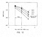
- FIG. 12 is a graph which shows the relation between fuel injection timing and torque (indicated means effective pressure (IMEP)) for the case where the EGR ratio is about 40% and in which the elevated temperature of the glow plug 32 is used as a parameter.
- FIG. 13 is a graph which shows the relation between fuel injection timing and cycle variation (IMEP COV %) for the case where the EGR ratio is about 40% and in which the elevated temperature of the glow plug 32 is used as a parameter.
Landscapes
- Engineering & Computer Science (AREA)
- Chemical & Material Sciences (AREA)
- Combustion & Propulsion (AREA)
- Mechanical Engineering (AREA)
- General Engineering & Computer Science (AREA)
- Combined Controls Of Internal Combustion Engines (AREA)
- Electrical Control Of Air Or Fuel Supplied To Internal-Combustion Engine (AREA)
Abstract
Description
- The present invention relates to control of a diesel engine.
- Conventionally, there has been proposed a technique for controlling a diesel engine in a combustion form (mode) corresponding to the load of the engine (see, for example, the below-listed Patent Document 1). Combustion forms (also called "combustion modes") of fuel employed in such engine control include a diffusion combustion mode for combusting fuel while injecting the fuel into a combustion chamber, and a premixed combustion mode (also called "homogeneous-charge compression combustion mode") for mixing fuel and air within a combustion chamber before igniting the fuel. In general, the diffusion combustion mode is used when the engine is in a high-load state, and the premixed combustion mode is used when the engine is in a low-load state. Also, in the premixed combustion, EGR control for re-circulating a large amount of exhaust gas to the intake side is used at the same time. It has been known that the amounts of NOx, soot, etc. can be reduced by switching the combustion mode to the premixed combustion mode.
- When the combustion mode is switched from the diffusion combustion mode to the premixed combustion mode or switched from a motoring state to the premixed combustion mode, nitrogen oxide (NOx), soot (soot itself or opacity of exhaust gas), combustion noise, etc. may be generated or their amounts may increase. In order to solve the above-described problems, in the below-listed
Patent Document 2, fuel injection is divided into pilot injection and main injection, and an increase or decrease in the fuel injection amount during such a transition period is finely adjusted. -
- [Patent Document 1] Japanese Patent Application Laid-Open (kokai) No.
2007-211612 - [Patent Document 2] Japanese Patent Application Laid-Open (kokai) No.
2010-236459 - It has been known that when such premixed combustion takes place in a diesel engine, fuel injection timing and EGR amount greatly affect the combustion. However, immediately after the combustion mode has been switched to the premixed combustion mode, the EGR amount cannot be controlled properly due to, for example, a temporary delay in introduction of exhaust gas. Therefor, it has been impossible to find a parameter for properly controlling the fuel injection timing.
- Also, conceivably, it is possible to predict the ratio of EGR or the oxygen concentration of intake gas through use of a model and on the basis of pieces of information from an intake pressure sensor, an air flow sensor, an exhaust oxygen sensor, an intake temperature sensor, and/or a like sensor, and control, on the basis of the predicted value, the fuel injection timing at the time when the combustion mode is switched to the premixed combustion mode. However, changes in the properties of fuel and the temperature of cooling water, and deterioration of various sensors with time are pieces of information which are difficult to predict. Since initial margins must be provided for these pieces of information, the oxygen concentration of intake gas, etc. have been impossible to predict accurately through use of the model-based method. Therefore, it has been difficult to accurately control the fuel injection timing at the time of switching to the premixed combustion mode even when the above-mentioned prediction is performed through use of a model.
- The present invention has been accomplished so as to solve, at least partially, the above-described problem, and the present invention can be embodied in the following modes.
- (1) According to a first mode of the present invention, a diesel engine control apparatus for controlling fuel injection timing of a diesel engine is provided. This diesel engine control apparatus comprises a cylinder pressure sensor for detecting cylinder pressure of the diesel engine; a parameter computation unit for computing a parameter which is related to change in the cylinder pressure of the diesel engine obtained from a signal output from the cylinder pressure sensor; and a control unit for controlling the fuel injection timing at the time when combustion in the diesel engine is switched to premixed combustion such that the parameter falls within a target range.
- According to this diesel engine control apparatus, the fuel injection timing at the time when combustion in the diesel engine is switched to premixed combustion is controlled such that a parameter related to change in the cylinder pressure of the diesel engine falls within a target range. According to the knowledge of the present inventors, change in the cylinder pressure of the diesel engine has a strong correlation with the ratio of EGR or the oxygen concentration of intake gas and the fuel injection timing. Accordingly, by computing the parameter related to change in the cylinder pressure of the diesel engine, and controlling the fuel injection timing such that the parameter falls within the target range, at least one index of combustion of the diesel engine, such as combustion noise, NOx, soot, etc., can be suppressed, as compared with the case of a conventional diesel engine, at the time of switching to the premixed combustion.
- (2) In such a diesel engine control apparatus, the switching to the premixed combustion may be performed in a state in which diffusion combustion is performed or in a motoring state. This is because a transition state in which the amount of EGR is unstable occurs when the switching to the premixed combustion is performed in either state. In such a transition state, the fuel injection timing control based on the parameter related to change in the cylinder pressure is preferred, because the fuel injection timing control can suppress at least one of the above-mentioned indexes of combustion such as combustion noise.
- (3) In the above-described diesel engine control apparatus, the parameter computation unit may compute, as the parameter, a mass fraction burned, and a pressure increase rate maximum value of the cylinder pressure or a heat release rate maximum value on the basis of the signal from the cylinder pressure sensor; and the control unit may perform fuel injection timing control based on the mass fraction burned when the fuel injection timing converges as a result of control based on the pressure increase rate maximum value or the heat release rate maximum value.
- This diesel engine control apparatus performs the control based on the pressure increase rate maximum value or the heat release rate maximum value, and, when the fuel injection timing converges as a result of that control, the diesel engine control apparatus performs the fuel injection timing control based on the mass fraction burned. Therefore, the fuel injection timing control can be continued even when the fuel injection timing converges as a result of the control based on the pressure increase rate maximum value or the heat release rate maximum value.
- (4) According to a second mode of the present invention, another diesel engine control apparatus for controlling fuel injection timing of a diesel engine is provided. This diesel engine control apparatus comprises a cylinder pressure sensor for detecting cylinder pressure of the diesel engine; and a control unit for controlling the fuel injection timing on the basis of a pressure increase rate maximum value or a heat release rate maximum value obtained from a signal from the cylinder pressure sensor.
- This diesel engine control apparatus can perform the fuel injection timing control by using the pressure increase rate maximum value or the heat release rate maximum value obtained from the signal output from the cylinder pressure sensor. Through use of the pressure increase rate maximum value or the heat release rate maximum value, at least one of combustion noise, NOx, and soot can be suppressed.
- (5) In such a diesel engine control apparatus, the control unit may control the fuel injection timing at the time when combustion in the diesel engine is switched to premixed combustion such that the pressure increase rate maximum value or the heat release rate maximum value falls within a target range. By controlling the fuel injection timing such that the pressure increase rate maximum value or the heat release rate maximum value falls within the target range, at least one of combustion noise, NOx, and soot can be suppressed properly.
- (6) In such a diesel engine control apparatus, the cylinder pressure sensor may be incorporated into a glow plug provided on the diesel engine. This configuration eliminates the necessity of separately providing a cylinder pressure sensor in the cylinder, whereby the influence on combustion within the cylinder can be mitigated.
- (7) When the combustion in the diesel engine is switched from diffusion combustion to premixed combustion, the glow plug may be energized such that the glow plug has a temperature of 900°C or higher. As a result of energizing the glow plug at the time of switching from the diffusion combustion to the premixed combustion, combustion is improved, and cycle variation is improved as compared with the case where the glow plug is not energized, and the range within which the fuel injection timing can be changed to cope with torque variation expands to the delay side. Therefore, a margin can be imparted to control in the diesel engine.
- (8) Such a glow plug may have a temperature increase speed such that the glow plug reaches 1200°C within a period of 0.5 sec to 3 sec. The higher the elevated temperature of the glow plug, the winder the range within which the fuel injection timing can be changed to cope with torque variation. Therefore, when a glow plug which can reach 1200°C within a short period of time is used, a state in which the control has a margin can be established within a short period of time.
- (9) A method for controlling fuel injection timing of a diesel engine is provided as a third mode of the present invention. This method comprises detecting cylinder pressure of the diesel engine; computing a parameter which is related to a change in the cylinder pressure of the diesel engine on the basis of the detected cylinder pressure; and controlling the fuel injection timing at the time when combustion in the diesel engine is switched to premixed combustion such that the parameter falls within a target range.
- According to such a method of controlling a diesel engine, the fuel injection timing at the time when combustion in the diesel engine is switched to premixed combustion is controlled such that a parameter related to change in the cylinder pressure of the diesel engine falls within a target range. According to the knowledge of the present inventors, change in the cylinder pressure of the diesel engine has a strong correlation with the ratio of EGR or the oxygen concentration of intake gas and the fuel injection timing. Accordingly, by computing the parameter related to change in the cylinder pressure of the diesel engine, and controlling the fuel injection timing such that the parameter falls within the target range, at least one of indexes of combustion of the diesel engine, such as combustion noise, NOx, soot, etc., can be suppressed, as compared with a conventional diesel engine, at the time of switching to the premixed combustion.
- (10) A method for controlling fuel injection timing of a diesel engine is provided as a fourth mode of the present invention. This method comprises detecting cylinder pressure of the diesel engine; and controlling the fuel injection timing on the basis of a pressure increase rate maximum value or a heat release rate maximum value obtained from the cylinder pressure. At least one of combustion noise, NOx, and soot can be suppressed by controlling the fuel injection timing by using the pressure increase rate maximum value or the heat release rate maximum value.
- All the plurality of constituent elements of each mode of the present invention are not essential. In order to solve, partially or entirely, the above-mentioned problem or yield, partially or entirely, the effects described in the present specification, a part of the elements may be properly modified, deleted, or replaced with another new element, or the limitation thereof may be partially removed. Also, in order to solve, partially or entirely, the above-mentioned problem or yield, partially or entirely, the effects described in the present specification, a portion or all of the above-described technical features contained in one mode of the present invention may be combined with a portion or all of the above-described technical features contained in other modes of the present invention to thereby attain an independent mode of the present invention.
- The present invention can be realized in various forms other than the diesel engine control apparatus. For example, the present invention can be realized in the form of, for example, a method of manufacturing the diesel engine control apparatus, a method of controlling the diesel engine control apparatus, a computer program for realizing the control method, or a non-temporary recording medium on which the computer program is recorded.
-
- [
FIG. 1 ] Schematic diagram of a control apparatus for a diesel engine which is a first embodiment of the present invention. - [
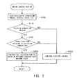
FIG. 2 ] Flowchart showing an engine control routine in the first embodiment. - [
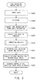
FIG. 3 ] Flowchart showing a fuel injection timing control routine in the first embodiment. - [
FIG. 4 ] Graph showing the relation between fuel injection timing and pressure increase rate maximum value in premixed combustion with EGR ratio used as a parameter. - [
FIGS. 5(A) through 5(C) ] Graphs showing a control example of the first embodiment along combustion cycles. - [
FIGS. 6(A) through 6(C) ] Graphs showing the control example of the first embodiment along time. - [
FIG. 7 ] Flowchart showing a fuel injection timing control routine in a second embodiment. - [
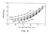
FIG. 8 ] Graph showing the relation between fuel injection timing and MFB in premixed combustion with EGR ratio used as a parameter. - [
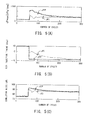
FIGS. 9(A) through 9(C) ] Graphs showing a control example of the second embodiment along combustion cycles. - [
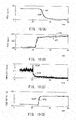
FIGS. 10(A) through 10(D) ] Graphs showing the control example of the second embodiment along time. - [
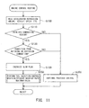
FIG. 11 ] Flowchart showing an engine control routine in a third embodiment. - [
FIG. 12 ] Graph showing the relation between fuel injection timing and torque with an increase in temperature of a glow plug used as a parameter. - [
FIG. 13 ] Graph showing the relation between fuel injection timing and cycle variation with an increase in temperature of a glow plug used as a parameter. - A diesel engine control apparatus which is common among first through third embodiments of the present invention will now be described. These embodiments are realized by hardware configurations which are substantially identical with one another. The diesel engine control apparatus denoted by 100 is mainly composed of a four-cylinder, direct-injection-type diesel engine (hereinafter simply referred to as an engine) 10; an intake-
exhaust system 20 which performs intake and exhaust operations, including recirculation of exhaust gas, for theengine 10; afuel injection value 30 for supplying fuel (light oil) to theengine 10; and anECU 70 for controlling the entire operation of theengine 10. - A. Hardware configuration of engine control apparatus:
- The
engine 10 includes four cylinders, and a piston is provided in each cylinder. Motion of the piston pushed downward as a result of combustion of fuel is converted to rotational motion of a crankshaft through a connecting rod. Arotational angle sensor 54 is provided to face the outer periphery of agear wheel 11 coupled to the crankshaft, and accurately detects the rotational angle of the crankshaft (hereinafter referred to as the "crank angle CA"). The shape of the gear wheel is determined such that the top dead center TDC and bottom dead center BDC of the piston in each cylinder are also detected. - The above-mentioned
fuel injection valve 30 and aglow plug 32 including a cylinder pressure sensor are provided on the cylinder head of theengine 10. Also, a water temperature sensor for detecting the temperature of cooling water and other components are provided on theengine 10. In response to an instruction from theECU 70, thefuel injection valve 30 opens so as to inject into a cylinder of theengine 10 high-pressure fuel supplied from afuel supply pump 24 via acommon rail 26. The timing of this injection represented by a crank angle from the top dead center TDC is fuel injection timing. In general, in the diffusion combustion mode, the fuel injection is performed in the vicinity of the top dead center TDC, and in the premixed combustion mode, the fuel injection is performed before the top dead center TDC. An operation of advancing the fuel injection timing in the crank angle CA will be referred to as "controlling the fuel injection timing to the advance side," and an operation of delaying the fuel injection timing in the crank angle CA will be referred to as "controlling the fuel injection timing to the delay side (retarding the fuel injection timing)." - The
glow plug 32, which is provided together with thefuel injection valve 30, includes a heater whose temperature reaches 900°C or higher within a short period of time when the heater is energized. Theglow plug 32 is used to assist combustion or stabilize combustion at low temperature. Although a cylinder pressure sensor is incorporated into theglow plug 32, this cylinder pressure sensor is not shown inFIG. 1 . Theglow plug 32 has a heater portion which moves in accordance with the pressure in the cylinder (cylinder pressure) acting on the forward end of the heater portion, and a diaphragm which receives the rear end of the heater portion. A piezo element is provided on the diaphragm. When the heater portion moves due to the cylinder pressure, the diaphragm is distorted, and the resistance of the piezo element changes. Theglow plug 32 having such a cylinder pressure sensor converts change in the resistance of the piezo element to an electrical signal, and outputs the electrical signal. This electrical signal is a signal corresponding to the cylinder pressure. Theglow plug 32 employed in the present embodiment has a ceramic heater which is provided in the heater portion and which reaches 1200°C within a period of time shorter than that in the case of a metal heater (0.5 to 3.0 sec in the present embodiment). Even when intake gas creates a cooling environment inside the cylinder, the interior of the cylinder can be heated to a temperature of about 1200°C by theglow plug 32 within a short period of time. - Next, the intake-
exhaust system 20 will be described. Oxygen is required for combustion in theengine 10, and such oxygen is derived from fresh air introduced from the outside. Fresh air is introduced from anintake pipe inlet 12 through an unillustrated air filter, and is taken into the intake-exhaust system 20 through anintake valve 14. Theengine 10 takes in this fresh air and exhaust gas recirculated from an exhaust system as a result of recirculation of of exhaust gas, and uses them for combustion. Gas taken in by theengine 10 will be referred to as "intake gas." A mixture of intake gag taken into the cylinder and fuel injected from thefuel injection valve 30 will be referred to as "gas-fuel mixture." - The intake-
exhaust system 20 includes aturbocharger 15, an inter cooler 17, an inter cooler passage throttle valve 18, and an intake manifold (hereinafter simply referred to as "manifold") 21 which are provided in this order from the upstream side between theintake pipe inlet 12 and the intake port of theengine 10. Meanwhile, on the downstream side of the exhaust port of theengine 10, there are provided abranch pipe 33, an exhaust side turbine of theturbocharger 15, anoxidation catalyst 34, an exhaust filter (DPF) 36, and anexhaust shutter 38. Although components on the downstream side of theexhaust shutter 38 are not illustrated, a well known muffler, etc. are provided, and exhaust gas is released to the atmosphere after being purified by theoxidation catalyst 34 and theDPF 36. - A
first EGR valve 37 is provided in a branch passage that branches off at a position before theexhaust shutter 38. Since the branch passage is connected to a flow passage through which fresh air is introduced from theintake pipe inlet 12, a portion of the exhaust gas is mixed with the fresh air there. A mixture of the fresh air and the exhaust gas is introduced into the intake side passage of theturbocharger 15. Theturbocharger 15 rotates the exhaust side turbine disposed in the exhaust passage extending from theengine 10 through use of the exhaust gas discharged from theengine 10. Since the exhaust side turbine is connected directly to an intake side turbine disposed on the intake side, the intake side turbine rotates and supercharges theengine 10 with the intake gas. As a result of supercharging by theturbocharger 15, the temperature of the intake gas increases due to adiabatic compression. The inter cooler 17 is provided so as to cool the intake gas. Since the intake gas (fresh air and exhaust gas) cooled by the inter cooler 17 is introduced into theengine 10 through the manifold 21, the exhaust gas is recirculated. The amount of recirculated exhaust gas can be controlled by adjusting the opening of thefirst EGR valve 37. This passage will be referred to as the "first EGR passage." - Meanwhile, a
branch pipe 33 provided immediately after the the exhaust port of theengine 10 is connected to the manifold 21 via anEGR cooler 35 and asecond EGR valve 22. This passage will be referred to as a second EGR passage for recirculating the exhaust gas from the exhaust side of theengine 10 to the intake side thereof. The EGR amount can be controlled by adjusting the opening of thesecond EGR valve 22 and the opening of the inter cooler passage throttle valve 18 provided immediately before the manifold 21. - A large number of sensors are provided in the above-described intake-
exhaust system 20. An intakegas temperature sensor 51 for detecting the temperature of the intake gas, an intake pressure sensor 52 for detecting the intake pressure, and an oxygen concentration sensor 53 for detecting the oxygen concentration of the intake gas are provided on the manifold 21. An exhaustgas temperature sensor 55 for detecting the temperature of the exhaust gas is provided downstream of thebranch pipe 33, and anopacity sensor 57 for detecting the opacity of the exhaust gas (the amount of generated soot) is provided before theDPF 36. Further, anNOx sensor 59 for detecting the amount of NOx is provided before theexhaust shutter 38. Of these sensors, the oxygen concentration sensor 53, theopacity sensor 57, theNOx sensor 59, etc. are provided so as to measure the performance of theengine control apparatus 100, which will be described later, and are not necessarily required for control of theengine 10 actually mounted on a vehicle. Other sensors may be omitted if they are not required for engine control. In the case where the various sensors such as the NOx sensor are not provided, the effects of the control apparatus of the embodiment may be confirmed by measuring various parameters through use of an exhaust gas analyzer, an opacimeter, etc. in a bench test. - The above-described various sensors and actuators such as valves are connected to the
ECU 70. TheECU 70 includes aCPU 71 for performing control, aROM 72, aRAM 73, aCAN 74 for performing communications with an in-vehicle LAN 80, aninput port 75 for receiving signals from the sensors, anoutput port 76 for outputting drive signals to the various valves, and abus 78 to which these elements and the ports are connected. Various sensors for detecting the operating state of the vehicle, such as anaccelerator sensor 61 for detecting the depression amount of an accelerator 62 (hereinafter referred to as the "accelerator depression amount α") and avehicle speed sensor 64, are also connected to theinput port 75. - B. First embodiment:
- B-1) Engine control:
- The
control apparatus 100 of the first embodiment performs the processing shown inFIGS. 2 and3 on the premise that thecontrol apparatus 100 has the above-described hardware configuration.FIG. 2 is a flowchart showing an engine control routine. When operation of theengine 10 is started, theECU 70 repeatedly executes the processing shown inFIG. 2 . When the processing of this routine is started, theECU 70 receives signals from the sensors such as theaccelerator sensor 61 and thevehicle speed sensor 64, and reads the accelerator depression amount α, the vehicle speed V, etc. (step S100). Subsequently, theECU 70 determines, from the accelerator depression amount α, the vehicle speed V, etc., whether or not the engine is in a region in which the engine operates in the premixed combustion mode (step S110). In general, the premixed combustion mode is employed in a low-speed/low-load region, and the diffusion combustion mode is selected in a region in which the load of the engine is high. Operation regions in which the engine operates in the premixed combustion mode may be determined in advance, and stored in theROM 72 or the like in the form of a map.
- The
- In the case where the
ECU 70 determines that the engine is in a region in which the engine is operated in the premixed combustion mode (step S110: "YES"), subsequently, theECU 70 determines whether or not the engine is in a transition from a motoring state or a region in which the engine is operated in the diffusion combustion mode (step S120). When the engine is in a transition from the motoring state or the region in which the engine is operated in the diffusion combustion mode, this means that, up to that point in time, the engine has been in the motoring state or has been operated in the diffusion combustion mode, and the engine (engine load) has moved to the region in which the engine is operated in the premixed combustion mode, as a result of changing of the operation state of the vehicle. In the case where theECU 70 determines that the engine is in such a transition state (step S120: "YES"), theECU 70 performs fuel injection control on the basis of the maximum value of pressure increase rate (step S200). This control will be described in detail later. - Meanwhile, when the
ECU 70 determines, from the operation state of the vehicle, that the engine is not in the region in which the engine is operated in the premixed combustion mode (step S110: "NO") or that the engine is not in a transition state although the engine is in the region in which the engine is operated in the premixed combustion mode (step S120: "NO"), theECU 70 proceeds to step S300 so as to continue the previous control which has been performed up to that time. The expression "previous control" means that when the engine has been operated in the diffusion combustion mode, the fuel injection control in the diffusion combustion mode is continued, and when the engine has been operated in the premixed combustion mode, the fuel injection control in the premixed combustion mode is continued. Notably, since combustion in the diffusion combustion mode or the premixed combustion mode is conventionally known, it will not be described in detail. Of course, various variations are present in the same diffusion combustion mode or the same premixed combustion mode. However, the routine ofFIG. 2 , excluding the processing in step S200, can be applied to any control. - B-2) Feedback control of fuel injection timing:
- Next, the fuel injection control in step S200 will be described.
FIG. 3 is a flowchart showing a fuel injection control routine which is executed as step S200. When this routine is started, first, theECU 70 performs sampling of data from the cylinder pressure sensor incorporated in the glow plug 32 (step S202). In actuality, theglow plug 32; i.e., the cylinder pressure sensor, is provided for each cylinder. Therefore, data from the cylinder pressure sensor obtained for each cylinder is read through theinput port 75 at predetermined intervals. In step S202, theECU 70 reads a sequence of data of the cylinder pressure sampled, at the predetermined intervals, for a cylinder in which the combustion stroke has been completed. - Next, the
ECU 70 performs filtering for the read sequence of data (step S203). Specifically, the filtering is low-pass filtering for removing high frequency components (specifically, noise) contained in the data of the cylinder pressure. The low-pass filtering can be realized by processing of obtaining the simple average or moving average of a plurality of successive data sets, or processing of integrating the data in a predetermined period of time. - Since the sampled data are the data obtained at the predetermined intervals, they are read on the time axis. Therefore, the
ECU 70 performs processing of converting the data to data on the crank angle through use of the crank angle CA obtained from the rotational angle sensor 54 (step S204). As will be described later, the control of fuel injection timing is performed on the basis of the crank angle CA. Therefore, processing after this point is performed on the basis of the crank angle CA. - Next, the
ECU 70 performs zero point correction for pressure by using the data of the cylinder pressure obtained on the basis of the signal from the cylinder pressure sensor incorporated in the glow plug 32 (step S205). The signal from the cylinder pressure sensor contains errors such as so-called zero point drift. In view of this, when the crank angle CA shows that the piston is located at the bottom dead center (BDC), correction is performed such that the cylinder pressure at that time is used as a reference value (zero point). As a result of this processing, noise and errors (e.g., zero point drift) contained in the signal can be removed. - Subsequently, the
ECU 70 performs processing for combustion analysis (step S210). In this processing, theECU 70 performs analysis of the combustion state required to obtain: - a fuel injection amount
- an EGR ratio, and
- the maximum value of the pressure increase rate of the cylinder pressure.
- Notably, in the combustion analysis (step S210), the
ECU 70 may obtain various parameters relating to combustion in addition to the maximum value dPmax of the pressure increase rate of the cylinder pressure which will be described later. For example, theECU 70 may obtain a mass fraction burned (MFB) which will be described later or a parameter for obtaining the mass fraction burned. - Subsequently, the
ECU 70 performs processing for determining the fuel injection amount q and the EGR ratio (step S221). The fuel injection amount q is determined on the basis of the required output of the engine. TheECU 70 obtains the fuel injection amount q on the basis of the negative pressure of the intake pipe, the accelerator depression amount α, the vehicle speed V, etc. Since the method of obtaining the fuel injection amount q is known, its description is omitted here. - The EGR ratio is the ratio of exhaust recirculation performed in the premixed combustion; i.e., the ratio of exhaust gas to fresh air. In general, in the case where the amount of oxygen necessary in the intake gas can be secured by performing supercharging through use of the
turbocharger 15, the higher the EGR ratio, the greater the degree to which NOx can be reduced. When the combustion mode is switched from the diffusion combustion mode to the premixed combustion mode, the EGR ratio is increased to, for example, a value as high as about 80%, within a relatively short period of time, from an EGR ratio (for example, about 25%) in the diffusion combustion mode. In the present embodiment, theECU 70 calculates the amount of oxygen required in a single cycle of the engine from the required torque, fuel injection amount, etc., in the premixed combustion mode, and obtains the maximum value of the EGR ratio which can secure a sufficient amount of oxygen and which can suppress the generation of soot, from a map or the like. - After obtaining the fuel injection amount q and the EGR ratio in this manner, the
ECU 70 performs processing for computing, on the basis of the data of the cylinder pressure, the maximum value dPmax of the pressure increase rate of the cylinder pressure in each combustion cycle of a single cylinder (step S222). The pressure increase rate is not the absolute value of the pressure, but is the ratio of pressure increase per unit crank angle CA. In general, the pressure increase rate assumes the largest value; i.e., the maximum value dPmax, at the beginning of the combustion stroke. - Next, the
ECU 70 performs feedback control of fuel injection timing on the basis of the pressure increase rate maximum value dPmax (step S223). Combustion in theengine 10 is not a continuous phenomenon, but is a discrete phenomenon. Namely, combustion is one of four strokes (i.e., intake, compression, combustion, and exhaust) performed for each cylinder. Therefore, the feedback control is performed to determine the fuel injection timing in the next combustion cycle. The feedback control of fuel injection timing is performed as follows. -
FIG. 4 is a graph showing the relation between the fuel injection timing and the pressure increase rate maximum value dPmax obtained by using the EGR ratio as a parameter. In the drawing, for example, a curve labeled "E50" shows the relation in the case where the EGR ratio is 50%. This graph shows the results of a test in which the pressure increase rate maximum value dPmax was obtained while the fuel injection timing was changed little by little with the EGR ratio fixed. In this example, in the case where the EGR ratio is low (55% or less), the greater the angle by which the fuel injection timing is delayed (the greater the degree to which the fuel injection timing approaches TDC), the smaller the pressure increase rate maximum value dPmax. - In view of the foregoing, in step S223, the
ECU 70 estimates the current EGR ratio, in accordance withFIG. 4 , from the fuel injection timing and the pressure increase rate maximum value dPmax for the cylinder in which the combustion cycle has been just completed, and obtains a fuel injection timing which renders the pressure increase rate maximum value dPmax in the next combustion cycle smaller than a predetermined value. For example, if the fuel injection timing in the premixed combustion mode in the cylinder in which the combustion cycle has been just completed is -14 [deg], and the pressure increase rate maximum value dPmax is 1000 [kPa/deg] (FIG. 4 , combustion point A1), the EGR ratio is estimated to be about 50%. Therefore, it is understood that when the pressure increase rate maximum value dPmax is to be controlled to about 500 [kPa/deg] in the next combustion cycle, the fuel injection timing is set to about - 6 [deg] (combustion point A2). The feedback control of fuel injection timing in step S223 controls the fuel injection timing such that the pressure increase rate maximum value dPmax falls within the range of about 300 to about 500 [kPa/deg]. - When the combustion cycle is repeated with the fuel injection timing controlled to the delay side at the beginning of a transition to the premixed combustion mode because the pressure increase rate maximum value dPmax is higher than a target range, the EGR ratio increases gradually, and the pressure increase rate maximum value dPmax decreases gradually. In the case where the fuel injection timing is maintained at -6 [deg], as shown in
FIG. 4 , the pressure increase rate maximum value dPmax becomes 200 [kPa/deg] or less when the EGR ratio increases to about 70% (combustion point A2 → A3 → A4). In this case, the pressure increase rate maximum value dPmax becomes lower than the lower limit of the target range. Therefore, this time, the pressure increase rate maximum value dPmax is increased by advancing the fuel injection timing (combustion point A4 → A5). This is the feedback control of fuel injection timing based on the pressure increase rate maximum value dPmax shown as step S223. InFIG. 4 , data are measured by changing the EGR ratio by 5% at a time. Therefore, combustion points are shown as discrete points. In actual combustion, the EGR ratio, the pressure increase rate maximum value dPmax, the fuel injection timing, etc. assume continuous values, and the combustion points are not limited to those on control curves shown inFIG. 4 for different EGR ratios. - B-3) Effects of first embodiment:
- The state of combustion when the above-described fuel injection timing control is performed will be described with reference to
FIGS. 5(A) through 5(C) andFIGS. 6(A) through 6(C) .FIGS. 5(A) through 5(C) are graphs which show the relation among the pressure increase rate maximum value dPmax, the fuel injection timing, and the combustion noise and in which the horizontal axis shows the number of combustion cycles.FIGS. 6(A) through 6(C) are graphs which show the amount of generated nitrogen oxide (NOx), the opacity representing the amount of generated soot, and the exhaust recirculation ratio (EGR ratio) and in which the horizontal axis shows the elapse of time.FIGS. 5(A) through 5(C) exemplify the case where the combustion mode was switched from the diffusion combustion mode to the premixed combustion mode at a timing near 50 cycles. Of the data shown inFIGS. 5(A) through 5(C) andFIGS. 6(A) through 6(C) , the combustion noise was measured through use of a noise meter disposed outside. The amount of NOx was measured through use of theNOx sensor 59, and the opacity was measured through use of theopacity sensor 57. The EGR ratio was computed from the oxygen concentration measured through use of the oxygen concentration sensor 53. Since these sensors are disposed at different locations on the intake-exhaust system 20, the sensors differ from one another in terms of the number of cycles or time between a point in time when the combustion mode is switched to the premixed combustion mode and a point in time when the influence of the switching appears on the output signal. InFIGS. 5(A) through 5(C) andFIGS. 6(A) through 6(C) , such differences are corrected. - In
FIG. 5(A) , a solid line JPI shows the case where the fuel injection timing is feedback-controlled by the present embodiment such that the pressure increase rate maximum value dPmax falls within the target range. Also, a solid line JPP shows the case where the feedback control of fuel injection timing based on the pressure increase rate maximum value dPmax is not performed. In the case where the feedback control of fuel injection timing is not performed, as shown by a sold line JFP inFIG. 5(B) , the fuel injection timing is fixed to -14 [deg] with respect to the TDC. In contrast, in the case where the feedback control of fuel injection timing based on the pressure increase rate maximum value dPmax is performed, as shown by a solid line JFI, the fuel injection timing is immediately controlled such that the advance angle becomes small. - When the combustion mode is switched to the premixed combustion mode as described above, the EGR ratio changes from about 25% to about 70% within a short period of time. This change is shown by solid lines JEI and JEP of
FIG. 6(C) . Notably, as described above, an increase in the EGR ratio immediately after the switching to the premixed combustion mode occurs because the openings of thefirst EGR valve 37, thesecond EGR valve 22, and the inter cooler passage throttle valve 18 have been changed. The EGR ratio gradually increases as a result of switching of each valve. A predetermined time (at least several seconds) is necessary for the EGR ratio to reach 70%. Further, since the amount of oxygen remaining in the exhaust gas decreases as a result of performance of the exhaust gas recirculation, the EGR ratio increases gradually. The final EGR ratio in the premixed combustion mode is, for example, about 80%. - As described above, when the combustion mode is switched from the diffusion combustion mode (or motoring) to the premixed combustion mode and the feedback control of fuel injection timing based on the pressure increase rate maximum value dPmax is performed while the EGR ratio is increased, the combustion noise decreases as shown by a solid line JCI in
FIG. 5(C) . InFIG. 5(C) , a solid line JCP shows the combustion noise in the case where the feedback control of fuel injection timing is not performed. As shown in these drawings, the combustion noise was decreased by about 10 [dB] by performing the feedback control of fuel injection timing, as compared with the case where the feedback control of fuel injection timing is not performed. - Also, as shown in
FIGS. 6(A) and 6(B) , generation of NOx and soot can be suppressed by performing the feedback control of fuel injection timing. InFIG. 6(A) , a solid line JNI shows the amount of generated NOx in the case where the feedback control is performed, and a solid line JNP shows the amount of generated NOx in the case where the feedback control is not performed. It is understood that an increase in the amount of generated NOx is suppressed over about 10 seconds after the switching to the premixed combustion mode. - In
FIG. 6(B) , a solid line JOI shows the opacity in the case where the feedback control is performed, and a solid line JOP shows the opacity in the case where the feedback control is not performed. It is understood that the opacity at the time of switching to the premixed combustion mode is improved. Notably, a decrease in torque was not observed even when the feedback control of fuel injection timing based on the pressure increase rate maximum value dPmax was performed. - C. Second embodiment:
- C-1) Feedback control of fuel injection timing:
- A second embodiment has the same hardware configuration as that of the first embodiment, but differs from the first embodiment in the feedback control of fuel injection timing.
FIG. 7 shows the details of the feedback control of fuel injection timing in the second embodiment. Since the control routine shown inFIG. 7 is the same as that of the first embodiment up to step S222 of the control routine shown inFIG. 3 , a first half of the control routine is not illustrated.
- A second embodiment has the same hardware configuration as that of the first embodiment, but differs from the first embodiment in the feedback control of fuel injection timing.
- C-1) Feedback control of fuel injection timing:
- In the second embodiment, after computing the pressure increase rate maximum value dPmax in step S222, the the
ECU 70 determines whether or not the fuel injection timing falls outside a control range for the control based on the pressure increase rate maximum value dPmax (step S230). The fuel injection timing is determined to fall outside the control range when the fuel injection timing having been controlled to the TDC side by the feedback control of fuel injection timing based on the pressure increase rate maximum value dPmax is controlled to the advance side as the pressure increase rate maximum value dPmax decreases, and the fuel injection timing is advanced beyond -14 [deg] in the crank angle. - In the case where the result of the determination in step S230 is "NO"; i.e., in the case where the fuel injection timing is judged to fall within the control range for the control based on the pressure increase rate maximum value dPmax, as in the first embodiment, the
ECU 70 performs the feedback control of fuel injection timing based on the pressure increase rate maximum value dPmax (step S223). Meanwhile, in the case where the result of the determination in step S230 is "Yes"; i.e., in the case where the fuel injection timing is judged to fall outside the control range for the control based on the pressure increase rate maximum value dPmax, theECU 70 performs processing for computing a mass fraction burned (MFB) (step S231). The mass fraction burned (MFB) shows the ratio of the amount of heat Qca released up to a certain crank angle ca to the maximum amount of heat Qmax released in a single combustion cycle. Namely, MFBca = 100·Qca/Qmax. In the second embodiment, MFB30 which is the ratio of the amount of heat released up to a crank angle of 30 degrees is used as the mass fraction burned (MFB). -
FIG. 8 is a graph which shows the relation between the fuel injection timing and the MFB30 and in which the EGR ratio is used as a parameter. As shown inFIG. 8 , the MFB30 increases monotonically with the fuel injection timing over a wide range of -22 degrees or higher in the crank angle ca. In addition, this trend is clearer when the EGR ratio is high. Accordingly, after the computation of the MFB30, theECU 70 performs the feedback control of fuel injection timing by using this MFB30 (step S232). After that, theECU 70 goes to a next process "NEXT" to thereby end the present control routine. - According to the above-described engine control apparatus of the second embodiment, the fuel injection timing is controlled as follows. In the case where the combustion mode is switched to the premixed combustion mode and a control for increasing the EGR ratio is performed simultaneously, the feedback control of fuel injection timing based on the pressure increase rate maximum value dPmax is started. After that, when the EGR ratio increases, and the fuel injection timing is advanced to about -14 [deg], the feedback control of fuel injection timing is switched to the feedback control of fuel injection timing based on the MFB30. When the EGR ratio increases, the fuel injection timing is controlled to maintain the pressure increase rate maximum value dPmax constant, whereby the fuel injection timing is controlled to the advance side. After that, upon convergence of the EGR ratio (the oxygen concentration of the intake gas) to a certain value, a change in the pressure increase rate maximum value dPmax when the fuel injection timing is controlled becomes relatively small. Meanwhile, in this region, the MFB30 has a sufficiently high sensitivity to a change in the fuel injection timing. Therefore, in this region, premixed combustion which is higher in thermal efficiency can be performed by performing the feedback control of fuel injection timing through use of the MFB30.
- C-2) Effects of second embodiment:
-
FIGS. 9(A) through 9(C) andFIGS. 10(A) through 10(D) show a control example in the second embodiment. As in the first embodiment, these drawings show changes in the pressure increase rate maximum value dPmax, the fuel injection timing, the combustion noise, the amount of generated NOx, the opacity, and the EGR ratio when the combustion mode is switched to the premixed combustion mode.FIG. 10(B) shows THC, which is the total amount of hydro carbon. Of the solid lines in each drawing, a solid line denoted by an abbreviated word whose final letter is I shows the characteristic in the second embodiment, and a solid line denoted by an abbreviated word whose final letter is P shows the characteristic in the first embodiment.
-
- As shown in
FIG. 9(B) , the feedback control of fuel injection timing is switched from the feedback control based on the pressure increase rate maximum value dPmax to the feedback control based on the MFB30 at a timing near 220 cycles. As a result, the fuel injection timing can be controlled to the advance side greatly, as compared with the case where the control based on the pressure increase rate maximum value dPmax is continued (solid line KFP). Also, it is understood that THC is improved. Notably, significant differences were not observed between the combustion noise, NOx, opacity, etc. in the second embodiment and those in the first embodiment. - Accordingly, the engine control apparatus of the second embodiment provides not only effects similar to those of the first embodiment, but also a remarkable effect of improving THC. Also, the fuel injection timing can be controlled to the advance side to a grater degree as compared with the first embodiment.
- D. Third embodiment:
- Next, a third embodiment of the present invention will be described. As shown in
FIG. 11 , an engine control apparatus of the third embodiment performs processing similar to that performed in the first embodiment. The third embodiment differs from the first embodiment in that processing for energizing the glow plug (step S130) is performed after step S120. The remaining processing is the same as that in the first embodiment.
- Next, a third embodiment of the present invention will be described. As shown in
- The third embodiment provides the following action and effects in addition to the action and effects of the first embodiment. The engine control apparatus of the third embodiment energizes the
glow plug 32 at the time of switching from the diffusion combustion mode (or motoring) to the premixed combustion mode. When theglow plug 32 is energized, it reaches 1200°C within 3 seconds.FIGS. 12 and13 show changes in torque (indicated means effective pressure (IMEP)) and cycle variation (IMEP COV %) in the case where the temperature inside the cylinder was increased by energizing theglow plug 32.FIG. 12 is a graph which shows the relation between fuel injection timing and torque (indicated means effective pressure (IMEP)) for the case where the EGR ratio is about 40% and in which the elevated temperature of theglow plug 32 is used as a parameter.FIG. 13 is a graph which shows the relation between fuel injection timing and cycle variation (IMEP COV %) for the case where the EGR ratio is about 40% and in which the elevated temperature of theglow plug 32 is used as a parameter. When the temperature within the cylinder exceeds at least 900°C, as shown inFIG. 13 , the cycle variation decreases. Accordingly, when comparison is made for the same IMEP value, it is found that the fuel injection timing in the case where theglow plug 32 is energized can be delayed (retarded) by about 1 CA [deg] as compared with the fuel injection timing in the case where theglow plug 32 is not energized. - As can be understood from
FIGS. 12 and13 , in the case where theglow plug 32 is energized, torque increases, and the cycle variation of torque is suppressed as compared with the case where theglow plug 32 is not energized. Therefore, even when the fuel injection timing is shifted toward the delay side by at least 1 CA [deg], the same torque and the same cycle variation of torque can be realized. The combustion noise, NOx, THC, and opacity were able to be decreased by controlling the fuel injection timing to the delay side by 1 CA [deg] in the premixed combustion mode. - E. Modifications:
- E-1) First modification:
- In the above-described embodiment, the pressure increase rate maximum value dPmax is used as a parameter relating to the cylinder pressure. However, other parameters may be used. For example, a heat release rate maximum value dQmax may be used. A heat release rate dQ corresponds to the amount of heat released per a predetermined crank angle CA, and can be computed from the measured cylinder pressure P at intervals corresponding to the predetermined crank angle CA. Of the computed heat release rates dQ, the largest value in the combustion cycle is referred to as the heat release rate maximum value dQmax. Since the heat release rate maximum value dQmax is a parameter having a strong correlation with the pressure increase rate maximum value dPmax, fuel injection timing control similar to those of the first through third embodiments can be performed through use of the heat release rate maximum value dQmax.
- Also, the heat release amount Q or the like can be used. At least one of the combustion noise, NOx, and opacity can be decreased by calculating the heat release amount Q or the like, and feedback-controlling the fuel injection timing such that the calculated heat release amount Q or the like falls within a predetermined target range.
- E-2) Second modification:
- In the above-described embodiment, the cylinder pressure is measured by the
glow plug 32 including a cylinder pressure sensor. However, the cylinder pressure sensor may be provided independently of theglow plug 32. In this case, the layout of the cylinder pressure sensor can be set freely. - E-3) Third modification:
- In the above-described embodiment, the feedback control of fuel injection timing is performed under the premise of the control characteristics shown in
FIG. 4 orFIG. 8 such that the pressure increase rate maximum value dPmax falls within a predetermined range (e.g., a range of 400 to 800 kPa/deg). However, the feedback control of fuel injection timing may be performed as follows. An upper limit of the pressure increase rate maximum value dPmax is determined (for example, 800 kPa/deg). When the pressure increase rate maximum value dPmax exceeds this upper limit, the fuel injection timing is controlled to the delay side by a predetermined crank angle CA (for example, 2 CA deg), and when the pressure increase rate maximum value dPmax is smaller than the upper limit, the fuel injection timing is controlled to the advance side by a predetermined crank angle CA (for example, 1 CA deg). This method makes it possible to control the fuel injection timing through simple judgment; i.e., by merely comparing the pressure increase rate maximum value dPmax with the upper limit. Notably, hysteresis having a predetermined width may be provided for the upper limit. - E-4) Fourth modification:
- In the above-described embodiment, a cylinder pressure sensor is incorporated in the
glow plug 32 provided for each cylinder. However, it is not required to provide the cylinder pressure sensor for each of all cylinders of a multi-cylinder engine. For example, in the case of an engine having four cylinders, the cylinder pressure sensor may be provided only for one or two of the four cylinders. The cylinder pressure or pressure increase rate maximum value dPmax of each of the cylinders for which the cylinder pressure sensor is not provided can be estimated from the values obtained for other cylinders. Alternatively, the fuel injection timing of each of the cylinders for which the cylinder pressure sensor is not provided may be controlled to follow the fuel injection timing of the cylinder for which the cylinder pressure sensor is provided. - E-5) Fifth modification:
- In the above-described embodiment, the feedback control of fuel injection timing is performed so as to control the fuel injection timing of each cylinder in the next combustion cycle by using the pressure increase rate maximum value dPmax or the heat release rate maximum value dQmax of the cylinder. However, instead of controlling the fuel injection timing of the same cylinder in the next combustion cycle, the feedback control may control the fuel injection timing of another cylinder; for example, a cylinder for which fuel injection is performed next. Also, in the case where computation of the fuel injection timing is not completed in time, the computed fuel injection timing may be applied to a combustion cycle following the next combustion cycle. Notably, the control of fuel injection timing performed through use of the pressure increase rate maximum value dPmax or the like is not limited to feedback control, and all types of PID controls may be applied. In the case where the reproducibility of variation of a parameter with change of the fuel injection timing can be obtained sufficiently, open-loop control may be used.
- E-6) Other modifications:
- In the above-described embodiment, the
glow plug 32 uses ceramic heater. However, theglow plug 32 may use a metal heater. - The number of cylinders of the diesel engine is not limited to four, and the diesel engine includes any number of cylinders. For example, the diesel engine may be a single-cylinder diesel engine or a multi-cylinder diesel engine such as a six-cylinder diesel engine.
- In the above-described embodiment, the target range to which the pressure increase rate maximum value dPmax is feedback-controlled is determined such that at least one of combustion noise, NOx, and opacity is decreased. However, the target range may be determined to decrease other parameters such as carbon monoxide CO.
- The present invention is not limited to the above-described embodiments and modifications, but may be embodied in various other forms without departing from the spirit of the invention. For example, in order to solve, partially or entirely, the above-mentioned problem or yield, partially or entirely, the above-mentioned effects, technical features of the embodiments and modifications corresponding to technical features of the modes described in the section "Summary of the Invention" can be replaced or combined as appropriate. Also, the technical feature(s) may be eliminated as appropriate unless the present specification mentions that the technical feature(s) is mandatory.
-
- 10: diesel engine
- 11: gear wheel
- 12: intake pipe
- 14: intake valve
- 15: turbocharger
- 17: inter cooler
- 18: inter cooler passage throttle valve
- 20: intake-exhaust system
- 21: manifold
- 22: second EGR valve
- 24: fuel supply pump
- 26: common rail
- 30: fuel injection valve
- 32: glow plug
- 33: branch pipe
- 34: oxidation catalyst
- 36: DPF
- 37: first EGR valve
- 38: exhaust shutter
- 51: intake gas temperature sensor
- 52: intake pressure sensor
- 53: oxygen concentration sensor
- 55: exhaust gas temperature sensor
- 57: opacity sensor
- 59: NOx sensor
- 61: accelerator sensor
- 62: accelerator
- 64: vehicle speed sensor
- 70: ECU
- 71: CPU
- 72: ROM
- 73: RAM
- 74: CAN
- 75: input port
- 76: output port
- 80: in-vehicle LAN
- 100: diesel engine control apparatus
Claims (10)
- A diesel engine control apparatus (FIG. 1, 100) for controlling fuel injection timing of a diesel engine, comprising:a cylinder pressure sensor (incorporated in a glow plug 32 of FIG. 1) for detecting cylinder pressure of the diesel engine (FIG. 1, 10) ;a parameter computation unit (FIG. 1, 70; FIG. 3, step S222) for computing a parameter (dPmax, etc.) which is related to change in the cylinder pressure of the diesel engine obtained from a signal output from the cylinder pressure sensor; anda control unit (FIG. 1, 70; FIG. 4, step S223) for controlling the fuel injection timing at the time when combustion in the diesel engine (10) is switched to premixed combustion such that the parameter falls within a target range.
- A diesel engine control apparatus according to claim 1, wherein the switching to the premixed combustion is performed in a state in which diffusion combustion is performed or in a motoring state (FIG. 3, step S120).
- A diesel engine control apparatus according to claim 1 or 2, wherein
the parameter computation unit (FIG. 1, 70) computes, as the parameter, a mass fraction burned, and a pressure increase rate maximum value of the cylinder pressure or a heat release rate maximum value on the basis of the signal from the cylinder pressure sensor (FIG. 7, steps S222, S231); and
the control unit (FIG. 1, 70) performs fuel injection timing control based on the mass fraction burned (FIG. 7, step S232) when the fuel injection timing converges as a result of control based on the pressure increase rate maximum value or the heat release rate maximum value (FIG. 7, step S230). - A diesel engine control apparatus (FIG. 1, 100) for controlling fuel injection timing of a diesel engine, comprising:a cylinder pressure sensor (incorporated in a glow plug 32 of FIG. 1) for detecting cylinder pressure of the diesel engine (FIG. 1, 10); anda control unit (FIG. 1, 70; FIG. 3, step S222) for controlling the fuel injection timing on the basis of a pressure increase rate maximum value or a heat release rate maximum value obtained from a signal from the cylinder pressure sensor.
- A diesel engine control apparatus according to claim 4, wherein the control unit (FIG. 1, 70) controls the fuel injection timing at the time when combustion in the diesel engine is switched to premixed combustion such that the pressure increase rate maximum value or the heat release rate maximum value falls within a target range (FIG. 3, S222).
- A diesel engine control apparatus according to any one of claims 1 to 5, wherein the cylinder pressure sensor is incorporated into a glow plug provided on the diesel engine (FIG. 1, 32).
- A diesel engine control apparatus according to claim 6, wherein the glow plug is energized such that the glow plug has a temperature of 900°C or higher (FIG. 11, S130) when the diesel engine is operated by premixed combustion (FIG. 11, S120).
- A diesel engine control apparatus according to claim 7, wherein the glow plug has a temperature increase speed such that the glow plug reaches 1200°C within a period of 0.5 sec to 3 sec.
- A method for controlling fuel injection timing of a diesel engine, comprising:detecting cylinder pressure of the diesel engine (FIG. 3, S202);computing a parameter which is related to change in the cylinder pressure of the diesel engine on the basis of the detected cylinder pressure (FIG. 3, S222); andcontrolling the fuel injection timing at the time when combustion in the diesel engine is switched to premixed combustion such that the parameter falls within a target range (FIG. 3, S223).
- A method for controlling fuel injection timing of a diesel engine, comprising:detecting cylinder pressure of the diesel engine (FIG. 3, S202); andcontrolling the fuel injection timing on the basis of a pressure increase rate maximum value or a heat release rate maximum value obtained from the cylinder pressure (FIG. 3, S223).
Applications Claiming Priority (1)
| Application Number | Priority Date | Filing Date | Title |
|---|---|---|---|
| JP2014063746A JP6302715B2 (en) | 2014-03-26 | 2014-03-26 | Diesel engine control apparatus and method |
Publications (2)
| Publication Number | Publication Date |
|---|---|
| EP2924269A2 true EP2924269A2 (en) | 2015-09-30 |
| EP2924269A3 EP2924269A3 (en) | 2016-01-13 |
Family
ID=53039661
Family Applications (1)
| Application Number | Title | Priority Date | Filing Date |
|---|---|---|---|
| EP15158818.3A Withdrawn EP2924269A3 (en) | 2014-03-26 | 2015-03-12 | Apparatus and method for controlling a diesel engine operating with premixed combustion |
Country Status (3)
| Country | Link |
|---|---|
| US (1) | US20150275810A1 (en) |
| EP (1) | EP2924269A3 (en) |
| JP (1) | JP6302715B2 (en) |
Cited By (1)
| Publication number | Priority date | Publication date | Assignee | Title |
|---|---|---|---|---|
| EP3369918A4 (en) * | 2015-10-27 | 2019-06-19 | Hitachi Automotive Systems, Ltd. | CONTROL DEVICE FOR INTERNAL COMBUSTION ENGINE |
Families Citing this family (5)
| Publication number | Priority date | Publication date | Assignee | Title |
|---|---|---|---|---|
| US9840998B2 (en) * | 2014-06-10 | 2017-12-12 | Avl Powertrain Engineering, Inc. | System and method for controlling fuel injection characteristics in an engine |
| GB2551528A (en) * | 2016-06-21 | 2017-12-27 | Jaguar Land Rover Ltd | Control system for a vehicle and method |
| DE112022001474T5 (en) * | 2021-05-07 | 2024-02-15 | Cummins Inc. | METHOD AND SYSTEMS FOR DETERMINING EFFECTIVE STATIONARY FLOW RATE FOR FUEL INJECTION DEVICES |
| CN114357748B (en) * | 2021-12-24 | 2022-09-23 | 哈尔滨工程大学 | Design method of combustion system based on target heat release rate |
| JP2024033635A (en) * | 2022-08-30 | 2024-03-13 | 株式会社トランストロン | Estimation method, estimation program, and estimation device |
Citations (2)
| Publication number | Priority date | Publication date | Assignee | Title |
|---|---|---|---|---|
| JP2007211612A (en) | 2006-02-07 | 2007-08-23 | Isuzu Motors Ltd | Engine control method and engine control system |
| JP2010236459A (en) | 2009-03-31 | 2010-10-21 | Mazda Motor Corp | Combustion control device and combustion control method for diesel engine |
Family Cites Families (20)
| Publication number | Priority date | Publication date | Assignee | Title |
|---|---|---|---|---|
| JP2003074853A (en) * | 2001-08-28 | 2003-03-12 | Honda Motor Co Ltd | Gas turbine engine combustor |
| WO2004022959A1 (en) * | 2002-09-09 | 2004-03-18 | Toyota Jidosha Kabushiki Kaisha | Control device of internal combustion engine |
| AT503662B1 (en) * | 2006-04-20 | 2007-12-15 | Piezocryst Advanced Sensorics | GLOW PLUG WITH INTEGRATED PRESSURE SENSOR |
| JP2008014249A (en) * | 2006-07-06 | 2008-01-24 | Toyota Motor Corp | Combustion control system for compression ignition internal combustion engine |
| JP4649383B2 (en) * | 2006-08-21 | 2011-03-09 | 本田技研工業株式会社 | Control device for internal combustion engine |
| JP2008128118A (en) * | 2006-11-21 | 2008-06-05 | Toyota Motor Corp | Control system for compression ignition internal combustion engine |
| DE102008004365A1 (en) * | 2008-01-15 | 2009-07-16 | Robert Bosch Gmbh | Method for operating an internal combustion engine, computer program and control unit |
| DE102008004361A1 (en) * | 2008-01-15 | 2009-07-16 | Robert Bosch Gmbh | Method for controlling an internal combustion engine, computer program and control unit |
| JP5292317B2 (en) * | 2008-02-20 | 2013-09-18 | 日本特殊陶業株式会社 | Ceramic heater and glow plug |
| US8055432B2 (en) * | 2008-08-07 | 2011-11-08 | The United States Of America As Represented By The Administrator Of The U.S. Environmental Protection Agency | Method and system of transient control for homogeneous charge compression ignition (HCCI) engines |
| JP2010196526A (en) * | 2009-02-24 | 2010-09-09 | Nissan Motor Co Ltd | Combustion control device of compression-ignition internal combustion engine |
| EP2423494A4 (en) * | 2009-04-22 | 2012-09-12 | Toyota Motor Co Ltd | CONTROL FOR INTERNAL COMBUSTION ENGINE |
| JP5396144B2 (en) * | 2009-05-14 | 2014-01-22 | 日本特殊陶業株式会社 | Glow plug energization control device and glow plug |
| JP2011064165A (en) * | 2009-09-18 | 2011-03-31 | Mitsubishi Fuso Truck & Bus Corp | Combustion control device of diesel engine |
| CN102822485B (en) * | 2010-03-26 | 2015-07-08 | 丰田自动车株式会社 | Combustion control device for internal combustion engine |
| JP2011256821A (en) * | 2010-06-11 | 2011-12-22 | Ngk Spark Plug Co Ltd | Energization control apparatus for glow plug |
| JP5838033B2 (en) * | 2011-02-25 | 2015-12-24 | 日本特殊陶業株式会社 | Glow plug with combustion pressure sensor |
| JP5062340B2 (en) * | 2011-03-11 | 2012-10-31 | 株式会社豊田自動織機 | Fuel injection device |
| WO2012125151A1 (en) * | 2011-03-15 | 2012-09-20 | International Engine Intellectual Property Company, Llc | Method and system of controlling combustion in a cylinder of an engine |
| JP5818217B2 (en) * | 2011-11-28 | 2015-11-18 | 学校法人明治大学 | Detection apparatus and detection method |
-
2014
- 2014-03-26 JP JP2014063746A patent/JP6302715B2/en not_active Expired - Fee Related
-
2015
- 2015-03-12 EP EP15158818.3A patent/EP2924269A3/en not_active Withdrawn
- 2015-03-25 US US14/667,960 patent/US20150275810A1/en not_active Abandoned
Patent Citations (2)
| Publication number | Priority date | Publication date | Assignee | Title |
|---|---|---|---|---|
| JP2007211612A (en) | 2006-02-07 | 2007-08-23 | Isuzu Motors Ltd | Engine control method and engine control system |
| JP2010236459A (en) | 2009-03-31 | 2010-10-21 | Mazda Motor Corp | Combustion control device and combustion control method for diesel engine |
Cited By (1)
| Publication number | Priority date | Publication date | Assignee | Title |
|---|---|---|---|---|
| EP3369918A4 (en) * | 2015-10-27 | 2019-06-19 | Hitachi Automotive Systems, Ltd. | CONTROL DEVICE FOR INTERNAL COMBUSTION ENGINE |
Also Published As
| Publication number | Publication date |
|---|---|
| EP2924269A3 (en) | 2016-01-13 |
| US20150275810A1 (en) | 2015-10-01 |
| JP2015183675A (en) | 2015-10-22 |
| JP6302715B2 (en) | 2018-03-28 |
Similar Documents
| Publication | Publication Date | Title |
|---|---|---|
| US10125716B2 (en) | Control apparatus for diesel engine and control method for diesel engine | |
| CN108779730B (en) | Control device for compression self-ignition engine | |
| JP3823553B2 (en) | Engine combustion control device | |
| CN105264207B (en) | The control device of internal combustion engine | |
| EP2924269A2 (en) | Apparatus and method for controlling a diesel engine operating with premixed combustion | |
| US10677186B2 (en) | Control apparatus for compression auto-ignition engine | |
| CN102439280A (en) | Control device for internal combustion engine | |
| CN106414975B (en) | Diesel engine control device and control method | |
| JP2009041488A (en) | Control device for internal combustion engine | |
| JP5331613B2 (en) | In-cylinder gas amount estimation device for internal combustion engine | |
| JP2002276444A (en) | Control unit for diesel engine | |
| JP5387914B2 (en) | In-cylinder inflow EGR gas flow rate estimation device for internal combustion engine | |
| JP2009203918A (en) | Operation control method of gasoline engine | |
| US20150275811A1 (en) | Diesel engine control apparatus, diesel engine control method, and method for designing diesel engine control apparatus | |
| JP2011058440A (en) | Control device for internal combustion engine | |
| JP2008267207A (en) | Diesel engine control device | |
| JP5608614B2 (en) | Engine EGR flow rate detection device | |
| JP2002155783A (en) | Fuel injection control device for diesel engine | |
| JP2007231883A (en) | Air-fuel ratio control device for internal combustion engine | |
| JP2010133353A (en) | Engine control device | |
| JP6542592B2 (en) | Control device for turbocharged engine | |
| JP2006274977A (en) | Control device for internal combustion engine | |
| JP6117631B2 (en) | Control device for internal combustion engine | |
| JP2016000970A (en) | Internal combustion engine control device | |
| JP5517110B2 (en) | EGR control device for internal combustion engine |
Legal Events
| Date | Code | Title | Description |
|---|---|---|---|
| PUAI | Public reference made under article 153(3) epc to a published international application that has entered the european phase |
Free format text: ORIGINAL CODE: 0009012 |
|
| AK | Designated contracting states |
Kind code of ref document: A2 Designated state(s): AL AT BE BG CH CY CZ DE DK EE ES FI FR GB GR HR HU IE IS IT LI LT LU LV MC MK MT NL NO PL PT RO RS SE SI SK SM TR |
|
| AX | Request for extension of the european patent |
Extension state: BA ME |
|
| PUAL | Search report despatched |
Free format text: ORIGINAL CODE: 0009013 |
|
| AK | Designated contracting states |
Kind code of ref document: A3 Designated state(s): AL AT BE BG CH CY CZ DE DK EE ES FI FR GB GR HR HU IE IS IT LI LT LU LV MC MK MT NL NO PL PT RO RS SE SI SK SM TR |
|
| AX | Request for extension of the european patent |
Extension state: BA ME |
|
| RIC1 | Information provided on ipc code assigned before grant |
Ipc: F02D 41/30 20060101AFI20151204BHEP Ipc: F02D 41/12 20060101ALI20151204BHEP Ipc: F02D 35/02 20060101ALI20151204BHEP Ipc: F02P 19/02 20060101ALI20151204BHEP Ipc: F02M 25/07 00000000ALI20151204BHEP |
|
| 17P | Request for examination filed |
Effective date: 20160608 |
|
| RBV | Designated contracting states (corrected) |
Designated state(s): AL AT BE BG CH CY CZ DE DK EE ES FI FR GB GR HR HU IE IS IT LI LT LU LV MC MK MT NL NO PL PT RO RS SE SI SK SM TR |
|
| STAA | Information on the status of an ep patent application or granted ep patent |
Free format text: STATUS: EXAMINATION IS IN PROGRESS |
|
| 17Q | First examination report despatched |
Effective date: 20210531 |
|
| STAA | Information on the status of an ep patent application or granted ep patent |
Free format text: STATUS: THE APPLICATION HAS BEEN WITHDRAWN |
|
| 18W | Application withdrawn |
Effective date: 20210916 |