EP2924258A1 - Emission control in rich burn natrual gas engines - Google Patents
Emission control in rich burn natrual gas engines Download PDFInfo
- Publication number
- EP2924258A1 EP2924258A1 EP15159209.4A EP15159209A EP2924258A1 EP 2924258 A1 EP2924258 A1 EP 2924258A1 EP 15159209 A EP15159209 A EP 15159209A EP 2924258 A1 EP2924258 A1 EP 2924258A1
- Authority
- EP
- European Patent Office
- Prior art keywords
- catalyst
- exhaust stream
- air
- ammonia slip
- engine
- Prior art date
- Legal status (The legal status is an assumption and is not a legal conclusion. Google has not performed a legal analysis and makes no representation as to the accuracy of the status listed.)
- Granted
Links
Images

Classifications
-
- F—MECHANICAL ENGINEERING; LIGHTING; HEATING; WEAPONS; BLASTING
- F01—MACHINES OR ENGINES IN GENERAL; ENGINE PLANTS IN GENERAL; STEAM ENGINES
- F01N—GAS-FLOW SILENCERS OR EXHAUST APPARATUS FOR MACHINES OR ENGINES IN GENERAL; GAS-FLOW SILENCERS OR EXHAUST APPARATUS FOR INTERNAL-COMBUSTION ENGINES
- F01N3/00—Exhaust or silencing apparatus having means for purifying, rendering innocuous, or otherwise treating exhaust
- F01N3/08—Exhaust or silencing apparatus having means for purifying, rendering innocuous, or otherwise treating exhaust for rendering innocuous
- F01N3/10—Exhaust or silencing apparatus having means for purifying, rendering innocuous, or otherwise treating exhaust for rendering innocuous by thermal or catalytic conversion of noxious components of exhaust
- F01N3/101—Three-way catalysts
-
- B—PERFORMING OPERATIONS; TRANSPORTING
- B01—PHYSICAL OR CHEMICAL PROCESSES OR APPARATUS IN GENERAL
- B01D—SEPARATION
- B01D53/00—Separation of gases or vapours; Recovering vapours of volatile solvents from gases; Chemical or biological purification of waste gases, e.g. engine exhaust gases, smoke, fumes, flue gases, aerosols
- B01D53/34—Chemical or biological purification of waste gases
- B01D53/92—Chemical or biological purification of waste gases of engine exhaust gases
- B01D53/94—Chemical or biological purification of waste gases of engine exhaust gases by catalytic processes
- B01D53/9459—Removing one or more of nitrogen oxides, carbon monoxide, or hydrocarbons by multiple successive catalytic functions; systems with more than one different function, e.g. zone coated catalysts
-
- F—MECHANICAL ENGINEERING; LIGHTING; HEATING; WEAPONS; BLASTING
- F01—MACHINES OR ENGINES IN GENERAL; ENGINE PLANTS IN GENERAL; STEAM ENGINES
- F01N—GAS-FLOW SILENCERS OR EXHAUST APPARATUS FOR MACHINES OR ENGINES IN GENERAL; GAS-FLOW SILENCERS OR EXHAUST APPARATUS FOR INTERNAL-COMBUSTION ENGINES
- F01N3/00—Exhaust or silencing apparatus having means for purifying, rendering innocuous, or otherwise treating exhaust
- F01N3/08—Exhaust or silencing apparatus having means for purifying, rendering innocuous, or otherwise treating exhaust for rendering innocuous
- F01N3/10—Exhaust or silencing apparatus having means for purifying, rendering innocuous, or otherwise treating exhaust for rendering innocuous by thermal or catalytic conversion of noxious components of exhaust
- F01N3/18—Exhaust or silencing apparatus having means for purifying, rendering innocuous, or otherwise treating exhaust for rendering innocuous by thermal or catalytic conversion of noxious components of exhaust characterised by methods of operation; Control
- F01N3/22—Control of additional air supply only, e.g. using by-passes or variable air pump drives
-
- B—PERFORMING OPERATIONS; TRANSPORTING
- B01—PHYSICAL OR CHEMICAL PROCESSES OR APPARATUS IN GENERAL
- B01D—SEPARATION
- B01D53/00—Separation of gases or vapours; Recovering vapours of volatile solvents from gases; Chemical or biological purification of waste gases, e.g. engine exhaust gases, smoke, fumes, flue gases, aerosols
- B01D53/34—Chemical or biological purification of waste gases
- B01D53/92—Chemical or biological purification of waste gases of engine exhaust gases
- B01D53/94—Chemical or biological purification of waste gases of engine exhaust gases by catalytic processes
- B01D53/9459—Removing one or more of nitrogen oxides, carbon monoxide, or hydrocarbons by multiple successive catalytic functions; systems with more than one different function, e.g. zone coated catalysts
- B01D53/9477—Removing one or more of nitrogen oxides, carbon monoxide, or hydrocarbons by multiple successive catalytic functions; systems with more than one different function, e.g. zone coated catalysts with catalysts positioned on separate bricks, e.g. exhaust systems
-
- F—MECHANICAL ENGINEERING; LIGHTING; HEATING; WEAPONS; BLASTING
- F01—MACHINES OR ENGINES IN GENERAL; ENGINE PLANTS IN GENERAL; STEAM ENGINES
- F01N—GAS-FLOW SILENCERS OR EXHAUST APPARATUS FOR MACHINES OR ENGINES IN GENERAL; GAS-FLOW SILENCERS OR EXHAUST APPARATUS FOR INTERNAL-COMBUSTION ENGINES
- F01N3/00—Exhaust or silencing apparatus having means for purifying, rendering innocuous, or otherwise treating exhaust
- F01N3/08—Exhaust or silencing apparatus having means for purifying, rendering innocuous, or otherwise treating exhaust for rendering innocuous
- F01N3/10—Exhaust or silencing apparatus having means for purifying, rendering innocuous, or otherwise treating exhaust for rendering innocuous by thermal or catalytic conversion of noxious components of exhaust
- F01N3/103—Oxidation catalysts for HC and CO only
-
- F—MECHANICAL ENGINEERING; LIGHTING; HEATING; WEAPONS; BLASTING
- F01—MACHINES OR ENGINES IN GENERAL; ENGINE PLANTS IN GENERAL; STEAM ENGINES
- F01N—GAS-FLOW SILENCERS OR EXHAUST APPARATUS FOR MACHINES OR ENGINES IN GENERAL; GAS-FLOW SILENCERS OR EXHAUST APPARATUS FOR INTERNAL-COMBUSTION ENGINES
- F01N3/00—Exhaust or silencing apparatus having means for purifying, rendering innocuous, or otherwise treating exhaust
- F01N3/08—Exhaust or silencing apparatus having means for purifying, rendering innocuous, or otherwise treating exhaust for rendering innocuous
- F01N3/10—Exhaust or silencing apparatus having means for purifying, rendering innocuous, or otherwise treating exhaust for rendering innocuous by thermal or catalytic conversion of noxious components of exhaust
- F01N3/105—General auxiliary catalysts, e.g. upstream or downstream of the main catalyst
- F01N3/106—Auxiliary oxidation catalysts
-
- F—MECHANICAL ENGINEERING; LIGHTING; HEATING; WEAPONS; BLASTING
- F01—MACHINES OR ENGINES IN GENERAL; ENGINE PLANTS IN GENERAL; STEAM ENGINES
- F01N—GAS-FLOW SILENCERS OR EXHAUST APPARATUS FOR MACHINES OR ENGINES IN GENERAL; GAS-FLOW SILENCERS OR EXHAUST APPARATUS FOR INTERNAL-COMBUSTION ENGINES
- F01N3/00—Exhaust or silencing apparatus having means for purifying, rendering innocuous, or otherwise treating exhaust
- F01N3/08—Exhaust or silencing apparatus having means for purifying, rendering innocuous, or otherwise treating exhaust for rendering innocuous
- F01N3/10—Exhaust or silencing apparatus having means for purifying, rendering innocuous, or otherwise treating exhaust for rendering innocuous by thermal or catalytic conversion of noxious components of exhaust
- F01N3/105—General auxiliary catalysts, e.g. upstream or downstream of the main catalyst
- F01N3/108—Auxiliary reduction catalysts
-
- F—MECHANICAL ENGINEERING; LIGHTING; HEATING; WEAPONS; BLASTING
- F01—MACHINES OR ENGINES IN GENERAL; ENGINE PLANTS IN GENERAL; STEAM ENGINES
- F01N—GAS-FLOW SILENCERS OR EXHAUST APPARATUS FOR MACHINES OR ENGINES IN GENERAL; GAS-FLOW SILENCERS OR EXHAUST APPARATUS FOR INTERNAL-COMBUSTION ENGINES
- F01N3/00—Exhaust or silencing apparatus having means for purifying, rendering innocuous, or otherwise treating exhaust
- F01N3/08—Exhaust or silencing apparatus having means for purifying, rendering innocuous, or otherwise treating exhaust for rendering innocuous
- F01N3/10—Exhaust or silencing apparatus having means for purifying, rendering innocuous, or otherwise treating exhaust for rendering innocuous by thermal or catalytic conversion of noxious components of exhaust
- F01N3/18—Exhaust or silencing apparatus having means for purifying, rendering innocuous, or otherwise treating exhaust for rendering innocuous by thermal or catalytic conversion of noxious components of exhaust characterised by methods of operation; Control
- F01N3/20—Exhaust or silencing apparatus having means for purifying, rendering innocuous, or otherwise treating exhaust for rendering innocuous by thermal or catalytic conversion of noxious components of exhaust characterised by methods of operation; Control specially adapted for catalytic conversion
-
- F—MECHANICAL ENGINEERING; LIGHTING; HEATING; WEAPONS; BLASTING
- F01—MACHINES OR ENGINES IN GENERAL; ENGINE PLANTS IN GENERAL; STEAM ENGINES
- F01N—GAS-FLOW SILENCERS OR EXHAUST APPARATUS FOR MACHINES OR ENGINES IN GENERAL; GAS-FLOW SILENCERS OR EXHAUST APPARATUS FOR INTERNAL-COMBUSTION ENGINES
- F01N3/00—Exhaust or silencing apparatus having means for purifying, rendering innocuous, or otherwise treating exhaust
- F01N3/08—Exhaust or silencing apparatus having means for purifying, rendering innocuous, or otherwise treating exhaust for rendering innocuous
- F01N3/10—Exhaust or silencing apparatus having means for purifying, rendering innocuous, or otherwise treating exhaust for rendering innocuous by thermal or catalytic conversion of noxious components of exhaust
- F01N3/24—Exhaust or silencing apparatus having means for purifying, rendering innocuous, or otherwise treating exhaust for rendering innocuous by thermal or catalytic conversion of noxious components of exhaust characterised by constructional aspects of converting apparatus
- F01N3/28—Construction of catalytic reactors
- F01N3/2892—Exhaust flow directors or the like, e.g. upstream of catalytic device
-
- F—MECHANICAL ENGINEERING; LIGHTING; HEATING; WEAPONS; BLASTING
- F01—MACHINES OR ENGINES IN GENERAL; ENGINE PLANTS IN GENERAL; STEAM ENGINES
- F01N—GAS-FLOW SILENCERS OR EXHAUST APPARATUS FOR MACHINES OR ENGINES IN GENERAL; GAS-FLOW SILENCERS OR EXHAUST APPARATUS FOR INTERNAL-COMBUSTION ENGINES
- F01N3/00—Exhaust or silencing apparatus having means for purifying, rendering innocuous, or otherwise treating exhaust
- F01N3/08—Exhaust or silencing apparatus having means for purifying, rendering innocuous, or otherwise treating exhaust for rendering innocuous
- F01N3/10—Exhaust or silencing apparatus having means for purifying, rendering innocuous, or otherwise treating exhaust for rendering innocuous by thermal or catalytic conversion of noxious components of exhaust
- F01N3/24—Exhaust or silencing apparatus having means for purifying, rendering innocuous, or otherwise treating exhaust for rendering innocuous by thermal or catalytic conversion of noxious components of exhaust characterised by constructional aspects of converting apparatus
- F01N3/30—Arrangements for supply of additional air
-
- F—MECHANICAL ENGINEERING; LIGHTING; HEATING; WEAPONS; BLASTING
- F01—MACHINES OR ENGINES IN GENERAL; ENGINE PLANTS IN GENERAL; STEAM ENGINES
- F01N—GAS-FLOW SILENCERS OR EXHAUST APPARATUS FOR MACHINES OR ENGINES IN GENERAL; GAS-FLOW SILENCERS OR EXHAUST APPARATUS FOR INTERNAL-COMBUSTION ENGINES
- F01N3/00—Exhaust or silencing apparatus having means for purifying, rendering innocuous, or otherwise treating exhaust
- F01N3/08—Exhaust or silencing apparatus having means for purifying, rendering innocuous, or otherwise treating exhaust for rendering innocuous
- F01N3/10—Exhaust or silencing apparatus having means for purifying, rendering innocuous, or otherwise treating exhaust for rendering innocuous by thermal or catalytic conversion of noxious components of exhaust
- F01N3/24—Exhaust or silencing apparatus having means for purifying, rendering innocuous, or otherwise treating exhaust for rendering innocuous by thermal or catalytic conversion of noxious components of exhaust characterised by constructional aspects of converting apparatus
- F01N3/30—Arrangements for supply of additional air
- F01N3/32—Arrangements for supply of additional air using air pump
-
- F—MECHANICAL ENGINEERING; LIGHTING; HEATING; WEAPONS; BLASTING
- F02—COMBUSTION ENGINES; HOT-GAS OR COMBUSTION-PRODUCT ENGINE PLANTS
- F02B—INTERNAL-COMBUSTION PISTON ENGINES; COMBUSTION ENGINES IN GENERAL
- F02B33/00—Engines characterised by provision of pumps for charging or scavenging
-
- F—MECHANICAL ENGINEERING; LIGHTING; HEATING; WEAPONS; BLASTING
- F02—COMBUSTION ENGINES; HOT-GAS OR COMBUSTION-PRODUCT ENGINE PLANTS
- F02B—INTERNAL-COMBUSTION PISTON ENGINES; COMBUSTION ENGINES IN GENERAL
- F02B37/00—Engines characterised by provision of pumps driven at least for part of the time by exhaust
-
- F—MECHANICAL ENGINEERING; LIGHTING; HEATING; WEAPONS; BLASTING
- F02—COMBUSTION ENGINES; HOT-GAS OR COMBUSTION-PRODUCT ENGINE PLANTS
- F02B—INTERNAL-COMBUSTION PISTON ENGINES; COMBUSTION ENGINES IN GENERAL
- F02B43/00—Engines characterised by operating on gaseous fuels; Plants including such engines
-
- B—PERFORMING OPERATIONS; TRANSPORTING
- B01—PHYSICAL OR CHEMICAL PROCESSES OR APPARATUS IN GENERAL
- B01D—SEPARATION
- B01D2255/00—Catalysts
- B01D2255/90—Physical characteristics of catalysts
- B01D2255/904—Multiple catalysts
-
- F—MECHANICAL ENGINEERING; LIGHTING; HEATING; WEAPONS; BLASTING
- F01—MACHINES OR ENGINES IN GENERAL; ENGINE PLANTS IN GENERAL; STEAM ENGINES
- F01N—GAS-FLOW SILENCERS OR EXHAUST APPARATUS FOR MACHINES OR ENGINES IN GENERAL; GAS-FLOW SILENCERS OR EXHAUST APPARATUS FOR INTERNAL-COMBUSTION ENGINES
- F01N2270/00—Mixing air with exhaust gases
- F01N2270/10—Mixing air with exhaust gases for rendering exhaust innocuous, e.g. by dilution
-
- F—MECHANICAL ENGINEERING; LIGHTING; HEATING; WEAPONS; BLASTING
- F01—MACHINES OR ENGINES IN GENERAL; ENGINE PLANTS IN GENERAL; STEAM ENGINES
- F01N—GAS-FLOW SILENCERS OR EXHAUST APPARATUS FOR MACHINES OR ENGINES IN GENERAL; GAS-FLOW SILENCERS OR EXHAUST APPARATUS FOR INTERNAL-COMBUSTION ENGINES
- F01N2610/00—Adding substances to exhaust gases
- F01N2610/08—Adding substances to exhaust gases with prior mixing of the substances with a gas, e.g. air
- F01N2610/085—Controlling the air supply
-
- Y—GENERAL TAGGING OF NEW TECHNOLOGICAL DEVELOPMENTS; GENERAL TAGGING OF CROSS-SECTIONAL TECHNOLOGIES SPANNING OVER SEVERAL SECTIONS OF THE IPC; TECHNICAL SUBJECTS COVERED BY FORMER USPC CROSS-REFERENCE ART COLLECTIONS [XRACs] AND DIGESTS
- Y02—TECHNOLOGIES OR APPLICATIONS FOR MITIGATION OR ADAPTATION AGAINST CLIMATE CHANGE
- Y02A—TECHNOLOGIES FOR ADAPTATION TO CLIMATE CHANGE
- Y02A50/00—TECHNOLOGIES FOR ADAPTATION TO CLIMATE CHANGE in human health protection, e.g. against extreme weather
- Y02A50/20—Air quality improvement or preservation, e.g. vehicle emission control or emission reduction by using catalytic converters
-
- Y—GENERAL TAGGING OF NEW TECHNOLOGICAL DEVELOPMENTS; GENERAL TAGGING OF CROSS-SECTIONAL TECHNOLOGIES SPANNING OVER SEVERAL SECTIONS OF THE IPC; TECHNICAL SUBJECTS COVERED BY FORMER USPC CROSS-REFERENCE ART COLLECTIONS [XRACs] AND DIGESTS
- Y02—TECHNOLOGIES OR APPLICATIONS FOR MITIGATION OR ADAPTATION AGAINST CLIMATE CHANGE
- Y02T—CLIMATE CHANGE MITIGATION TECHNOLOGIES RELATED TO TRANSPORTATION
- Y02T10/00—Road transport of goods or passengers
- Y02T10/10—Internal combustion engine [ICE] based vehicles
- Y02T10/12—Improving ICE efficiencies
Definitions
- the present invention relates generally to an emission control system/after treatment system for an engine and, in particular, to a passive mid bed air injection apparatus for an engine.
- Natural gas engines are utilized in a number of different environments, including gas compression applications, power generation applications, oil field power generation applications, etc. Natural gas engines can be provided with a catalytic converter that converts pollutants/emissions from an exhaust stream of the engine into less toxic pollutants.
- engine exhaust was manipulated to be slightly richer (e.g., greater amount of fuel such that ratio of air to fuel is below stoichiometry) to improve reduction of pollutants from the exhaust stream such as unburned or partially burned hydrocarbons (HC), nitrogen oxides (NO x ), etc.
- the present invention provides a passive mid bed air injection apparatus for an engine.
- the mid bed air injection apparatus includes a three way catalyst positioned in an exhaust stream of the engine, the three way catalyst configured to reduce NO x , CO and HC from the exhaust stream.
- the mid bed air injection apparatus includes an ammonia slip catalyst positioned in the exhaust stream of the engine.
- the ammonia slip catalyst is positioned downstream from the three way catalyst.
- the ammonia slip catalyst is configured to oxidize NH 3 and CO from the exhaust stream.
- the mid bed air injection apparatus includes an oxygen input disposed between the three way catalyst and the ammonia slip catalyst such that the oxygen input is configured to deliver air downstream from the three way catalyst and upstream from the ammonia slip catalyst.
- the oxygen input can receive the air from a charged side of a forced induction device and deliver the air to the exhaust stream entering the ammonia slip catalyst.
- the present invention provides a passive mid bed air injection apparatus for an engine.
- the mid bed air injection apparatus includes a three way catalyst positioned in an exhaust stream of the engine, the three way catalyst configured to reduce NO x , CO and HC from the exhaust stream.
- the mid bed air injection apparatus includes an ammonia slip catalyst positioned in the exhaust stream of the engine.
- the ammonia slip catalyst is positioned downstream from the three way catalyst.
- the ammonia slip catalyst is configured to oxidize NH 3 and CO from the exhaust stream.
- the mid bed air injection apparatus includes an air mixer disposed between the three way catalyst and the ammonia slip catalyst.
- the mid bed air injection apparatus includes an oxygen input disposed between the three way catalyst and the ammonia slip catalyst such that the oxygen input is configured to deliver air downstream from the three way catalyst and upstream from the ammonia slip catalyst.
- the oxygen input can receive the air from a charged side of a forced induction device and deliver the air to the air mixer. The air and the exhaust stream are mixed prior to entering the ammonia slip catalyst.
- the present invention provides a method of reducing NH 3 emissions in an engine.
- the method includes providing a three way catalyst in an exhaust stream of the engine, the three way catalyst configured to reduce NO x and CO from the exhaust stream.
- the method includes providing an ammonia slip catalyst in the exhaust stream of the engine and downstream from the three way catalyst.
- the method includes delivering air from a charged side of a forced induction device to the exhaust stream entering the ammonia slip catalyst.
- Example embodiments that incorporate one or more aspects of the present invention are described and illustrated in the drawings. These illustrated examples are not intended to be a limitation on the present invention. For example, one or more aspects of the present invention can be utilized in other embodiments and even other types of devices. Moreover, certain terminology is used herein for convenience only and is not to be taken as a limitation on the present invention. Still further, in the drawings, the same reference numerals are employed for designating the same elements.
- FIG. 1 schematically illustrates an example engine system 10. It will be appreciated that the engine system 10 is illustrated somewhat generically/schematically in FIG. 1 for ease of illustration. Indeed, the engine system 10 includes any number of constructions, configurations, and/or structures, including pumps, cylinders, conduits, passageways, or the like.
- the engine system 10 includes an engine 12, such as a natural gas engine, hydrocarbon-fueled engine, etc., for example.
- the engine 12 includes any number of internal combustion engines, some of which may use natural gas.
- the engine 12 can be used in association with any number of environments/applications. Some example environments/applications in which the engine 12 may be provided include, but are not limited to, gas compression applications, power generation applications, oil field power generation applications, or the like.
- the engine 12 is capable of converting energy into mechanical motion.
- the engine 12 illustrated in FIG. 1 and described herein is not specifically limited to the use of natural gas.
- An exhaust stream 14 can flow from the engine 12.
- the exhaust stream 14 can include any number/mixture of gaseous emissions and/or byproducts from combustion of fuels by the engine 12.
- the exhaust stream 14 may include some or all of carbon monoxide (CO), unburned or partially burned hydrocarbons (HC), nitrogen oxides (NO x ), and/or ammonia (NH 3 ).
- the engine system 10 can include a passive mid bed air injection apparatus 20 for the engine 12.
- a forced induction device 22 can be included as part of the mid bed air injection apparatus 20.
- the forced induction device 22 is illustrated generically/schematically in FIG. 1 , as it will be appreciated that the forced induction device 22 includes any number of different structures.
- the forced induction device 22 includes a turbocharger.
- the forced induction device 22 includes a supercharger.
- the forced induction device 22 can increase efficiency of the engine 12 by providing extra air into a combustion chamber of the engine 12.
- the supercharger can be used for boosting air intake for the engine 12. In other examples, including the illustrated example, the supercharger can also be used for increasing and/or boosting air to a catalyst (e.g., catalyst assembly 40). In some or all of these examples, the supercharger may include belt and/or gear driven superchargers, belt and/or gear driven piston pumps/compressors, centrifugal superchargers, vane superchargers, lobe (roots) superchargers, screw superchargers, etc. Indeed, it is to be appreciated that the supercharger includes any number of variations, constructions, structures, etc., some of which may be listed herein.
- the forced induction device 22 (e.g., turbocharger, supercharger, etc.) is in fluid communication with an air intake 24.
- the air intake 24 can supply air to the forced induction device 22.
- the forced induction device 22 can receive the air from the air intake 24.
- the forced induction device 22 can receive the exhaust stream 14 from the engine 12.
- the forced induction device 22 can compress the air received from the air intake 24.
- the exhaust stream 14 can cause rotation of a turbine within the forced induction device 22, which leads to compression of the air.
- a compressor is belt driven, which leads to compression of the air.
- Compressed air 28 can exit a charged side 30 of the forced induction device 22.
- the compressed air 28 can be treated with an air cooler 32.
- the compressed air 28 can flow through the air cooler 32, whereupon the compressed air 28 is cooled.
- cooled air 34 from the air cooler 32 is mixed with fuel 36 from a fuel supply 38. The combined cooled air 34 and fuel 36 can be provided to the engine 12 for combustion.
- the exhaust stream 14 can flow from the forced induction device 22 towards a catalyst assembly 40 of the mid bed air injection apparatus 20.
- the catalyst assembly 40 includes a single housing while, in other examples, the catalyst assembly 40 includes a plurality of housings. In the illustrated example, the catalyst assembly 40 can be positioned downstream from the engine 12 and the forced induction device 22.
- the engine system 10 may include a sensor, such as an O 2 sensor 48.
- the O 2 sensor 48 can be positioned upstream from the catalyst assembly 40, such that the O 2 sensor 48 comprises a pre catalyst sensor.
- the O 2 sensor 48 can be positioned within the flow path of the exhaust stream 14, such that the O 2 sensor 48 can determine an air/fuel ratio of the exhaust stream 14.
- the O 2 sensor 48 is not limited to the illustrated position.
- the O 2 sensor 48 may additionally or alternatively be positioned downstream from the catalyst assembly 40, such that the O 2 sensor 48 (or additional O 2 sensor) comprises a post catalyst sensor.
- the O 2 sensor 48 may be positioned within the catalyst assembly 40 (e.g., between the three way catalyst 50 and ammonia slip catalyst 54).
- the catalyst assembly 40 can include one or more catalyst materials.
- the catalyst assembly 40 includes a three way catalyst 50 (illustrated as "TWC" in FIG. 1 ).
- the three way catalyst 50 is illustrated generically/schematically in FIG. 1 , as the three way catalyst 50 includes any number of constructions.
- the three way catalyst 50 CO 2 and/or H 2 O.
- the three way catalyst 50 can reduce NO x , CO, and/or HC, other byproducts from the engine 12 may not be efficiently removed/reduced from the exhaust stream 14 by the three way catalyst 50.
- the engine 12 and the three way catalyst 50 may operate at a slightly richer mixture (e.g., greater amount of fuel such that ratio of air to fuel is below stoichiometry).
- the three way catalyst 50 may be more efficient and effective in removing/reducing NO x , CO, and/or HC from the exhaust stream 14.
- a consequence of operating at the slightly richer mixture is that relatively higher concentrations of NH 3 (ammonia) and CO (carbon monoxide) are generated and present in the exhaust stream 14 downstream from the three way catalyst 50.
- the catalyst assembly 40 can include an ammonia slip catalyst 54 (illustrated as "ASC" in FIG. 1 ) positioned in the exhaust stream 14 of engine 12.
- ASC ammonia slip catalyst 54
- the ammonia slip catalyst 54 is positioned downstream from the three way catalyst 50 and downstream from an air mixer 58.
- the ammonia slip catalyst 54 is illustrated generically/schematically in FIG. 1 , as the ammonia slip catalyst 54 includes any number of constructions.
- the ammonia slip catalyst 54 includes one or more layers of active catalyst materials disposed on a surface/substrate. Based on the active catalyst materials, the ammonia slip catalyst 54 can oxidize (e.g., convert) any number of materials in the exhaust stream 14.
- the ammonia slip catalyst 54 can oxidize (e.g., convert) at least some of NH3 and/or CO from the exhaust stream 14.
- the ammonia slip catalyst 54 includes a molecular sieve that supports one or more materials that can oxidize NH 3 .
- the materials that can oxidize NH 3 include, but are not limited to, transition metals, platinum group metals (e.g., ruthenium (Ru), rhodium
- NH 3 and CO from the exhaust stream 14 can be converted to N 2 , CO 2 , etc.
- the catalyst assembly 40 can include the air mixer 58.
- the air mixer 58 is disposed between the three way catalyst 50 and the ammonia slip catalyst 54.
- the air mixer 58 may be disposed downstream from the three way catalyst 50 and upstream from the ammonia slip catalyst 54.
- the air mixer 58 can be disposed within the exhaust stream 14, such that after the exhaust stream 14 exits the three way catalyst 50, some or all of the exhaust stream 14 may flow through the air mixer 58.
- the air mixer 58 can mix the exhaust stream 14 with another source of gas or fluid.
- the air mixer 58 can include any number of sizes/dimensions for mixing air.
- the air mixer 58 comprises a relatively larger diameter mixer such that the air mixer 58 has a size that is similar to a catalyst element size.
- the air mixer 58 comprises a relatively smaller diameter mixer such that the air mixer 58 has a size that is similar to an exhaust pipe size. Indeed, it is to be appreciated that, based on the specific requirements of the engine system 10, exhaust stream 14, etc., the air mixer 58 may include a wide range of sizes.
- the mid bed air injection apparatus 20 can include an oxygen input 70.
- the oxygen input 70 can extend between the charged side 30 of the forced induction device 22 (e.g., from the air cooler 32) and the catalyst assembly 40.
- a first end 72 of the oxygen input 70 is in fluid communication with the charged side 30 of the forced induction device 22 while an opposing second end 74 of the oxygen input 70 is in fluid communication with the catalyst assembly 40.
- a portion of the oxygen input 70 (e.g., the second end 74) is disposed between the three way catalyst 50 and the ammonia slip catalyst 54.
- the oxygen input 70 includes a tube, channel, conduit, pipe, passageway, or the like through which air is delivered from the charged side 30 of the forced induction device 22 (e.g., from the air cooler 32) to the catalyst assembly 40.
- the oxygen input 70 can receive the air from the charged side 30 of the forced induction device 22 (e.g., from the air cooler 32) and deliver the air to the exhaust stream 14 that enters the ammonia slip catalyst 54.
- the air can be delivered passively to the oxygen input 70, such as through an opening at a location along the charged side 30, such as in or after the air cooler 32.
- the oxygen input 70 delivers the air downstream from the three way catalyst 50 and upstream from the ammonia slip catalyst 54. As such, the oxygen input 70 can bypass the engine 12.
- the oxygen input 70 can deliver the air to the air mixer 58. It is to be appreciated that in some examples, there may be a limit on the quantity of air that is delivered through the oxygen input 70 to the exhaust stream 14 upstream from the ammonia slip catalyst 54.
- the air from the oxygen input 70 and the exhaust stream 14 may be mixed prior to entering the ammonia slip catalyst 54.
- the combination of air and the exhaust stream 14 entering the ammonia slip catalyst 54 is slightly leaner (e.g., larger amount of air such that ratio of air to fuel is above stoichiometry).
- the ammonia slip catalyst 54 may be more efficient and effective in oxidizing (e.g., converting/reducing) the NH 3 and CO from the exhaust stream 14.
- the catalyst assembly 40 may not be provided with the air mixer 58. Instead, the air from the oxygen input 70 and the exhaust stream 14 may be combined prior to entering the ammonia slip catalyst 54 without the need for the air mixer 58. In such an example, the ammonia slip catalyst 54 may still oxidize the NH 3 and CO from the exhaust stream 14.
- the engine system 10 is not specifically limited to the illustrated structure/configuration. Indeed, in further possible examples, the engine system 10 may include other structures not illustrated herein.
- the engine system 10 may include a dedicated (to mid-bed injection) air pump and/or air compressor. Such air pumps and/or air compressors may be utilized in engine systems 10 having draw-thru applications.
- the exhaust stream 14 and air can pass through and exit the ammonia slip catalyst 54 in the form of exhaust 90.
- the exhaust 90 is illustrated generically/schematically with an arrowhead for ease of illustration in FIG. 1 .
- the exhaust 90 can exit from an outlet, vent or the like in the catalyst assembly 40 downstream from the ammonia slip catalyst 54.
- the exhaust 90 can have a reduced quantity of pollutants, including carbon monoxide (CO), unburned or partially burned hydrocarbons (HC), nitrogen oxides (NO x ), and/or ammonia (NH 3 ).
- active controls e.g., pumps, valves, etc.
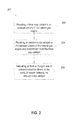
- FIG. 2 an example method 200 of reducing NH 3 emissions in the engine 12 is illustrated.
- the method 200 can be performed in association with the engine system 10 illustrated in FIG. 1 .
- the method 200 includes a step 202 of providing the three way catalyst 50 in the exhaust stream 14 of the engine 12. As illustrated in FIG. 1 , the three way catalyst 50, as part of the catalyst assembly 40, is positioned downstream from the engine 12. As such, exhaust within the exhaust stream 14 is emitted from the engine 12, with the exhaust stream 14 being passed to and through the three way catalyst 50.
- the method 200 includes a step 204 of providing the ammonia slip catalyst 54 in the exhaust stream 14 of the engine 12 and downstream from the three way catalyst 50.
- the ammonia slip catalyst 54 as part of the catalyst assembly 40, is positioned downstream from the engine 12.
- the ammonia slip catalyst 54 is positioned downstream from the three way catalyst 50.
- the exhaust stream 14 may pass through the three way catalyst 50 and, after exiting the three way catalyst 50, may enter the ammonia slip catalyst 54.
- the method 200 includes a step 206 of delivering air from the charged side 30 of the forced induction device 22 to the exhaust stream 14 entering the ammonia slip catalyst 54.
- the air can be delivered from the charged side 30 of the forced induction device 22 (e.g., from the air cooler 32 in this example) to the catalyst assembly 40 through the oxygen input 70.
- the second end 74 of the oxygen input 70 can be in fluid communication with the air mixer 58, such that air from the oxygen input 70 is mixed with the exhaust stream 14. This mixture occurs downstream from the three way catalyst 50 and upstream from the ammonia slip catalyst 54.
- the exhaust stream combined with the air that contacts the ammonia slip catalyst 54 is a slightly leaner mixture (e.g., larger amount of air such that ratio of air to fuel is above stoichiometry).
- the ammonia slip catalyst 54 may be more efficient and more effective in reducing (e.g., converting/oxidizing) the NH 3 and CO from the exhaust stream 14.
Landscapes
- Engineering & Computer Science (AREA)
- Chemical & Material Sciences (AREA)
- Chemical Kinetics & Catalysis (AREA)
- Combustion & Propulsion (AREA)
- General Engineering & Computer Science (AREA)
- Mechanical Engineering (AREA)
- Health & Medical Sciences (AREA)
- Toxicology (AREA)
- Materials Engineering (AREA)
- Biomedical Technology (AREA)
- Oil, Petroleum & Natural Gas (AREA)
- General Chemical & Material Sciences (AREA)
- Analytical Chemistry (AREA)
- Environmental & Geological Engineering (AREA)
- Exhaust Gas After Treatment (AREA)
- Exhaust Gas Treatment By Means Of Catalyst (AREA)
Abstract
Description
- The present invention relates generally to an emission control system/after treatment system for an engine and, in particular, to a passive mid bed air injection apparatus for an engine.
- Natural gas engines are utilized in a number of different environments, including gas compression applications, power generation applications, oil field power generation applications, etc. Natural gas engines can be provided with a catalytic converter that converts pollutants/emissions from an exhaust stream of the engine into less toxic pollutants. In the past, engine exhaust was manipulated to be slightly richer (e.g., greater amount of fuel such that ratio of air to fuel is below stoichiometry) to improve reduction of pollutants from the exhaust stream such as unburned or partially burned hydrocarbons (HC), nitrogen oxides (NO x ), etc.
- As a consequence of the engine exhaust being slightly richer, a larger amount of other pollutants, such as ammonia (NH3), carbon monoxide (CO), etc., were present in the exhaust stream. Accordingly, there is a need, and it would be beneficial, to efficiently remove pollutants (e.g., ammonia (NH3) and carbon monoxide (CO)) from the exhaust stream by increasing the amount of air in the catalytic converter without the use of active controls such that a ratio of air to fuel is above stoichiometry.
- The following presents a simplified summary of the invention in order to provide a basic understanding of some example aspects of the invention. This summary is not an extensive overview of the invention. Moreover, this summary is not intended to identify critical elements of the invention nor delineate the scope of the invention. The sole purpose of the summary is to present some concepts of the invention in simplified form as a prelude to the more detailed description that is presented later.
- In accordance with one aspect, the present invention provides a passive mid bed air injection apparatus for an engine. The mid bed air injection apparatus includes a three way catalyst positioned in an exhaust stream of the engine, the three way catalyst configured to reduce NOx, CO and HC from the exhaust stream. The mid bed air injection apparatus includes an ammonia slip catalyst positioned in the exhaust stream of the engine. The ammonia slip catalyst is positioned downstream from the three way catalyst. The ammonia slip catalyst is configured to oxidize NH3 and CO from the exhaust stream. The mid bed air injection apparatus includes an oxygen input disposed between the three way catalyst and the ammonia slip catalyst such that the oxygen input is configured to deliver air downstream from the three way catalyst and upstream from the ammonia slip catalyst. The oxygen input can receive the air from a charged side of a forced induction device and deliver the air to the exhaust stream entering the ammonia slip catalyst.
- In accordance with another aspect, the present invention provides a passive mid bed air injection apparatus for an engine. The mid bed air injection apparatus includes a three way catalyst positioned in an exhaust stream of the engine, the three way catalyst configured to reduce NOx, CO and HC from the exhaust stream. The mid bed air injection apparatus includes an ammonia slip catalyst positioned in the exhaust stream of the engine. The ammonia slip catalyst is positioned downstream from the three way catalyst. The ammonia slip catalyst is configured to oxidize NH3 and CO from the exhaust stream. The mid bed air injection apparatus includes an air mixer disposed between the three way catalyst and the ammonia slip catalyst. The mid bed air injection apparatus includes an oxygen input disposed between the three way catalyst and the ammonia slip catalyst such that the oxygen input is configured to deliver air downstream from the three way catalyst and upstream from the ammonia slip catalyst. The oxygen input can receive the air from a charged side of a forced induction device and deliver the air to the air mixer. The air and the exhaust stream are mixed prior to entering the ammonia slip catalyst.
- In accordance with another aspect, the present invention provides a method of reducing NH3 emissions in an engine. The method includes providing a three way catalyst in an exhaust stream of the engine, the three way catalyst configured to reduce NOx and CO from the exhaust stream. The method includes providing an ammonia slip catalyst in the exhaust stream of the engine and downstream from the three way catalyst. The method includes delivering air from a charged side of a forced induction device to the exhaust stream entering the ammonia slip catalyst. Various aspects of the present invention will become apparent to those skilled in the art to which the present invention relates upon reading the following description with reference to the accompanying drawings, in which:
-
FIG. 1 is generic/schematic illustration of an example engine system for an engine including a passive mid bed air injection apparatus in accordance with an aspect of the present invention; and -
FIG. 2 is a flowchart depicting a method of reducing NH3 emissions in an engine. - Example embodiments that incorporate one or more aspects of the present invention are described and illustrated in the drawings. These illustrated examples are not intended to be a limitation on the present invention. For example, one or more aspects of the present invention can be utilized in other embodiments and even other types of devices. Moreover, certain terminology is used herein for convenience only and is not to be taken as a limitation on the present invention. Still further, in the drawings, the same reference numerals are employed for designating the same elements.
-
FIG. 1 schematically illustrates anexample engine system 10. It will be appreciated that theengine system 10 is illustrated somewhat generically/schematically inFIG. 1 for ease of illustration. Indeed, theengine system 10 includes any number of constructions, configurations, and/or structures, including pumps, cylinders, conduits, passageways, or the like. - The
engine system 10 includes anengine 12, such as a natural gas engine, hydrocarbon-fueled engine, etc., for example. In general, theengine 12 includes any number of internal combustion engines, some of which may use natural gas. Theengine 12 can be used in association with any number of environments/applications. Some example environments/applications in which theengine 12 may be provided include, but are not limited to, gas compression applications, power generation applications, oil field power generation applications, or the like. In some examples, theengine 12 is capable of converting energy into mechanical motion. Theengine 12 illustrated inFIG. 1 and described herein is not specifically limited to the use of natural gas. Indeed, in some possible examples, theengine 12 may include fuels that run in an engine at λ (excess air ratio) = ~1.0 and may include fuels such as propane, ethane, process gases, residue gases, field gases, gasoline, hydrocarbon fuels, diesel, natural gas, etc. - An
exhaust stream 14 can flow from theengine 12. Theexhaust stream 14 can include any number/mixture of gaseous emissions and/or byproducts from combustion of fuels by theengine 12. In some examples, theexhaust stream 14 may include some or all of carbon monoxide (CO), unburned or partially burned hydrocarbons (HC), nitrogen oxides (NO x ), and/or ammonia (NH3). - The
engine system 10 can include a passive mid bedair injection apparatus 20 for theengine 12. In some examples, a forcedinduction device 22 can be included as part of the mid bedair injection apparatus 20. The forcedinduction device 22 is illustrated generically/schematically inFIG. 1 , as it will be appreciated that the forcedinduction device 22 includes any number of different structures. In one possible example, the forcedinduction device 22 includes a turbocharger. In another example, the forcedinduction device 22 includes a supercharger. In general, the forcedinduction device 22 can increase efficiency of theengine 12 by providing extra air into a combustion chamber of theengine 12. - In some examples, the supercharger can be used for boosting air intake for the
engine 12. In other examples, including the illustrated example, the supercharger can also be used for increasing and/or boosting air to a catalyst (e.g., catalyst assembly 40). In some or all of these examples, the supercharger may include belt and/or gear driven superchargers, belt and/or gear driven piston pumps/compressors, centrifugal superchargers, vane superchargers, lobe (roots) superchargers, screw superchargers, etc. Indeed, it is to be appreciated that the supercharger includes any number of variations, constructions, structures, etc., some of which may be listed herein. - The forced induction device 22 (e.g., turbocharger, supercharger, etc.) is in fluid communication with an
air intake 24. In an example, theair intake 24 can supply air to the forcedinduction device 22. In operation, the forcedinduction device 22 can receive the air from theair intake 24. Likewise, in some examples, the forcedinduction device 22 can receive theexhaust stream 14 from theengine 12. In general, the forcedinduction device 22 can compress the air received from theair intake 24. In some examples, such as when the forcedinduction device 22 includes a turbocharger, to assist in compressing the air, theexhaust stream 14 can cause rotation of a turbine within the forcedinduction device 22, which leads to compression of the air. In other examples, such as when the forcedinduction device 22 includes a supercharger, a compressor is belt driven, which leads to compression of the air. -
Compressed air 28 can exit a chargedside 30 of the forcedinduction device 22. In some examples, thecompressed air 28 can be treated with anair cooler 32. For example, thecompressed air 28 can flow through theair cooler 32, whereupon thecompressed air 28 is cooled. In one example, cooledair 34 from theair cooler 32 is mixed withfuel 36 from afuel supply 38. The combined cooledair 34 andfuel 36 can be provided to theengine 12 for combustion. - The
exhaust stream 14 can flow from the forcedinduction device 22 towards acatalyst assembly 40 of the mid bedair injection apparatus 20. In some examples, thecatalyst assembly 40 includes a single housing while, in other examples, thecatalyst assembly 40 includes a plurality of housings. In the illustrated example, thecatalyst assembly 40 can be positioned downstream from theengine 12 and the forcedinduction device 22. - In one possible example, the
engine system 10 may include a sensor, such as an O2 sensor 48. In the illustrated example, the O2 sensor 48 can be positioned upstream from thecatalyst assembly 40, such that the O2 sensor 48 comprises a pre catalyst sensor. The O2 sensor 48 can be positioned within the flow path of theexhaust stream 14, such that the O2 sensor 48 can determine an air/fuel ratio of theexhaust stream 14. The O2 sensor 48 is not limited to the illustrated position. In other examples, the O2 sensor 48 may additionally or alternatively be positioned downstream from thecatalyst assembly 40, such that the O2 sensor 48 (or additional O2 sensor) comprises a post catalyst sensor. In other examples, the O2 sensor 48 may be positioned within the catalyst assembly 40 (e.g., between the threeway catalyst 50 and ammonia slip catalyst 54). - The
catalyst assembly 40 can include one or more catalyst materials. In this example, thecatalyst assembly 40 includes a three way catalyst 50 (illustrated as "TWC" inFIG. 1 ). The threeway catalyst 50 is illustrated generically/schematically inFIG. 1 , as the threeway catalyst 50 includes any number of constructions. In some examples, the threeway catalyst 50 CO2 and/or H2O. - While the three
way catalyst 50 can reduce NOx, CO, and/or HC, other byproducts from theengine 12 may not be efficiently removed/reduced from theexhaust stream 14 by the threeway catalyst 50. In an example, theengine 12 and the threeway catalyst 50 may operate at a slightly richer mixture (e.g., greater amount of fuel such that ratio of air to fuel is below stoichiometry). By operating at a slightly richer mixture, the threeway catalyst 50 may be more efficient and effective in removing/reducing NOx, CO, and/or HC from theexhaust stream 14. However, a consequence of operating at the slightly richer mixture is that relatively higher concentrations of NH3 (ammonia) and CO (carbon monoxide) are generated and present in theexhaust stream 14 downstream from the threeway catalyst 50. - To assist in oxidizing/removing the NH3 and CO, the
catalyst assembly 40 can include an ammonia slip catalyst 54 (illustrated as "ASC" inFIG. 1 ) positioned in theexhaust stream 14 ofengine 12. In the illustrated example, theammonia slip catalyst 54 is positioned downstream from the threeway catalyst 50 and downstream from anair mixer 58. Theammonia slip catalyst 54 is illustrated generically/schematically inFIG. 1 , as theammonia slip catalyst 54 includes any number of constructions. In some examples, theammonia slip catalyst 54 includes one or more layers of active catalyst materials disposed on a surface/substrate. Based on the active catalyst materials, theammonia slip catalyst 54 can oxidize (e.g., convert) any number of materials in theexhaust stream 14. - The
ammonia slip catalyst 54 can oxidize (e.g., convert) at least some of NH3 and/or CO from theexhaust stream 14. In one possible example, theammonia slip catalyst 54 includes a molecular sieve that supports one or more materials that can oxidize NH3. In some examples, the materials that can oxidize NH3 include, but are not limited to, transition metals, platinum group metals (e.g., ruthenium (Ru), rhodium - (Rh), palladium (Pd), rhenium (Re), iridium (Ir), platinum (Pt), and/or mixtures thereof), etc.. In this example, at least some of the NH3 and CO from the
exhaust stream 14 can be converted to N2, CO2, etc. - The
catalyst assembly 40 can include theair mixer 58. In some examples, theair mixer 58 is disposed between the threeway catalyst 50 and theammonia slip catalyst 54. For example, theair mixer 58 may be disposed downstream from the threeway catalyst 50 and upstream from theammonia slip catalyst 54. Theair mixer 58 can be disposed within theexhaust stream 14, such that after theexhaust stream 14 exits the threeway catalyst 50, some or all of theexhaust stream 14 may flow through theair mixer 58. In general, theair mixer 58 can mix theexhaust stream 14 with another source of gas or fluid. - The
air mixer 58 can include any number of sizes/dimensions for mixing air. In one possible example, theair mixer 58 comprises a relatively larger diameter mixer such that theair mixer 58 has a size that is similar to a catalyst element size. In another example, theair mixer 58 comprises a relatively smaller diameter mixer such that theair mixer 58 has a size that is similar to an exhaust pipe size. Indeed, it is to be appreciated that, based on the specific requirements of theengine system 10,exhaust stream 14, etc., theair mixer 58 may include a wide range of sizes. - The mid bed
air injection apparatus 20 can include anoxygen input 70. Theoxygen input 70 can extend between the chargedside 30 of the forced induction device 22 (e.g., from the air cooler 32) and thecatalyst assembly 40. In the illustrated example, afirst end 72 of theoxygen input 70 is in fluid communication with the chargedside 30 of the forcedinduction device 22 while an opposingsecond end 74 of theoxygen input 70 is in fluid communication with thecatalyst assembly 40. In such an example, a portion of the oxygen input 70 (e.g., the second end 74) is disposed between the threeway catalyst 50 and theammonia slip catalyst 54. - The
oxygen input 70 includes a tube, channel, conduit, pipe, passageway, or the like through which air is delivered from the chargedside 30 of the forced induction device 22 (e.g., from the air cooler 32) to thecatalyst assembly 40. Theoxygen input 70 can receive the air from the chargedside 30 of the forced induction device 22 (e.g., from the air cooler 32) and deliver the air to theexhaust stream 14 that enters theammonia slip catalyst 54. The air can be delivered passively to theoxygen input 70, such as through an opening at a location along the chargedside 30, such as in or after theair cooler 32. In this example, theoxygen input 70 delivers the air downstream from the threeway catalyst 50 and upstream from theammonia slip catalyst 54. As such, theoxygen input 70 can bypass theengine 12. - In the illustrated example, the
oxygen input 70 can deliver the air to theair mixer 58. It is to be appreciated that in some examples, there may be a limit on the quantity of air that is delivered through theoxygen input 70 to theexhaust stream 14 upstream from theammonia slip catalyst 54. The air from theoxygen input 70 and theexhaust stream 14 may be mixed prior to entering theammonia slip catalyst 54. As a result of providing air from theoxygen input 70 to theammonia slip catalyst 54, the combination of air and theexhaust stream 14 entering theammonia slip catalyst 54 is slightly leaner (e.g., larger amount of air such that ratio of air to fuel is above stoichiometry). By operating at a slightly leaner mixture, theammonia slip catalyst 54 may be more efficient and effective in oxidizing (e.g., converting/reducing) the NH3 and CO from theexhaust stream 14. - It will be appreciated that in some examples, the
catalyst assembly 40 may not be provided with theair mixer 58. Instead, the air from theoxygen input 70 and theexhaust stream 14 may be combined prior to entering theammonia slip catalyst 54 without the need for theair mixer 58. In such an example, theammonia slip catalyst 54 may still oxidize the NH3 and CO from theexhaust stream 14. - Additionally, it will be appreciated that the
engine system 10 is not specifically limited to the illustrated structure/configuration. Indeed, in further possible examples, theengine system 10 may include other structures not illustrated herein. For example, theengine system 10 may include a dedicated (to mid-bed injection) air pump and/or air compressor. Such air pumps and/or air compressors may be utilized inengine systems 10 having draw-thru applications. - The
exhaust stream 14 and air can pass through and exit theammonia slip catalyst 54 in the form ofexhaust 90. It will be appreciated that theexhaust 90 is illustrated generically/schematically with an arrowhead for ease of illustration inFIG. 1 . In this example, theexhaust 90 can exit from an outlet, vent or the like in thecatalyst assembly 40 downstream from theammonia slip catalyst 54. As a result of the threeway catalyst 50 andammonia slip catalyst 54, theexhaust 90 can have a reduced quantity of pollutants, including carbon monoxide (CO), unburned or partially burned hydrocarbons (HC), nitrogen oxides (NO x ), and/or ammonia (NH3). Furthermore, since the air is passively transferred to theoxygen input 70, active controls (e.g., pumps, valves, etc.) need not be provided to control flow of the air from theoxygen input 70 to theammonia slip catalyst 54. - Turning now to
FIG. 2 , anexample method 200 of reducing NH3 emissions in theengine 12 is illustrated. Themethod 200 can be performed in association with theengine system 10 illustrated inFIG. 1 . - The
method 200 includes astep 202 of providing the threeway catalyst 50 in theexhaust stream 14 of theengine 12. As illustrated inFIG. 1 , the threeway catalyst 50, as part of thecatalyst assembly 40, is positioned downstream from theengine 12. As such, exhaust within theexhaust stream 14 is emitted from theengine 12, with theexhaust stream 14 being passed to and through the threeway catalyst 50. - The
method 200 includes astep 204 of providing theammonia slip catalyst 54 in theexhaust stream 14 of theengine 12 and downstream from the threeway catalyst 50. As illustrated inFIG. 1 , theammonia slip catalyst 54, as part of thecatalyst assembly 40, is positioned downstream from theengine 12. Likewise, within thecatalyst assembly 40, theammonia slip catalyst 54 is positioned downstream from the threeway catalyst 50. As such, theexhaust stream 14 may pass through the threeway catalyst 50 and, after exiting the threeway catalyst 50, may enter theammonia slip catalyst 54. - The
method 200 includes astep 206 of delivering air from the chargedside 30 of the forcedinduction device 22 to theexhaust stream 14 entering theammonia slip catalyst 54. As illustrated inFIG. 1 , the air can be delivered from the chargedside 30 of the forced induction device 22 (e.g., from theair cooler 32 in this example) to thecatalyst assembly 40 through theoxygen input 70. In this example, thesecond end 74 of theoxygen input 70 can be in fluid communication with theair mixer 58, such that air from theoxygen input 70 is mixed with theexhaust stream 14. This mixture occurs downstream from the threeway catalyst 50 and upstream from theammonia slip catalyst 54. As such, the exhaust stream combined with the air that contacts theammonia slip catalyst 54 is a slightly leaner mixture (e.g., larger amount of air such that ratio of air to fuel is above stoichiometry). As a result of this leaner mixture, theammonia slip catalyst 54 may be more efficient and more effective in reducing (e.g., converting/oxidizing) the NH3 and CO from theexhaust stream 14. - The invention has been described with reference to the example embodiments described above. Modifications and alterations will occur to others upon a reading and understanding of this specification. Example embodiments incorporating one or more aspects of the invention are intended to include all such modifications and alterations insofar as they come within the scope of the appended claims.
- Various aspects and embodiments of the present invention are defined by the following numbered clauses:
- 1. A passive mid bed air injection apparatus for an engine, the mid bed air injection apparatus including:
- a three way catalyst positioned in an exhaust stream of the engine, the three way catalyst configured to reduce NOx, CO and HC from the exhaust stream;
- an ammonia slip catalyst positioned in the exhaust stream of the engine, the ammonia slip catalyst positioned downstream from the three way catalyst, the ammonia slip catalyst configured to oxidize NH3 and CO from the exhaust stream; and
- an oxygen input disposed between the three way catalyst and the ammonia slip catalyst such that the oxygen input is configured to deliver air downstream from the three way catalyst and upstream from the ammonia slip catalyst, the oxygen input configured to receive the air from a charged side of a forced induction device and deliver the air to the exhaust stream entering the ammonia slip catalyst.
- 2. The mid bed air injection apparatus of clause 1, wherein the forced induction device includes a turbocharger.
- 3. The mid bed air injection apparatus of any preceding clause, wherein the forced induction device includes a supercharger.
- 4. The mid bed air injection apparatus of any preceding clause, wherein the oxygen input from the charged side of the forced induction device to the exhaust stream is configured to bypass the engine.
- 5. The mid bed air injection apparatus of any preceding clause, further including an air mixer disposed between the three way catalyst and the ammonia slip catalyst.
- 6. The method of any preceding clause, wherein the engine includes fuels including propane, ethane, process gases, residue gases, field gases, and gasoline.
- 7. The mid bed air injection apparatus of any preceding clause, wherein the ammonia slip catalyst is configured to oxidize NH3 from the exhaust stream by oxidizing at least some of the NH3 to N2.
- 8. A passive mid bed air injection apparatus for an engine, the mid bed air injection apparatus including:
- a three way catalyst positioned in an exhaust stream of the engine, the three way catalyst configured to reduce NOx, CO and HC from the exhaust stream;
- an ammonia slip catalyst positioned in the exhaust stream of the engine, the ammonia slip catalyst positioned downstream from the three way catalyst, the ammonia slip catalyst configured to oxidize NH3 and CO from the exhaust stream;
- an air mixer disposed between the three way catalyst and the ammonia slip catalyst; and
- an oxygen input disposed between the three way catalyst and the ammonia slip catalyst such that the oxygen input is configured to deliver air downstream from the three way catalyst and upstream from the ammonia slip catalyst, the oxygen input configured to receive the air from a charged side of a forced induction device and deliver the air to the air mixer, wherein the air and the exhaust stream are mixed by the air mixer prior to entering the ammonia slip catalyst.
- 9. The mid bed air injection apparatus of any preceding clause, wherein the forced induction device includes a turbocharger.
- 10. The mid bed air injection apparatus of any preceding clause, wherein the forced induction device includes a supercharger.
- 11. The mid bed air injection apparatus of any preceding clause, wherein the oxygen input from the charged side of the forced induction device to the exhaust stream is configured to bypass the engine.
- 12. The method of any preceding clause, wherein the engine includes fuels including propane, ethane, process gases, residue gases, field gases, and gasoline.
- 13. The mid bed air injection apparatus of any preceding clause, wherein the ammonia slip catalyst is configured to oxidize NH3 from the exhaust stream by oxidizing at least some of the NH3 to N2.
- 14. A method of oxidizing NH3 emissions in an engine, the method including:
- providing a three way catalyst in an exhaust stream of the engine, the three way catalyst configured to reduce NOx and CO from the exhaust stream;
- providing an ammonia slip catalyst in the exhaust stream of the engine and downstream from the three way catalyst; and
- delivering air from a charged side of a forced induction device to the exhaust stream entering the ammonia slip catalyst.
- 15. The method of any preceding clause, wherein delivering the air from the charged side of the forced induction device to the exhaust stream includes bypassing the engine.
- 16. The method of any preceding clause, wherein delivering the air from the charged side of the forced induction device to the exhaust stream includes bypassing the three way catalyst, the ammonia slip catalyst configured to oxidize NH3 and CO from the exhaust stream.
- 17. The method of any preceding clause, wherein the forced induction device includes a turbocharger.
- 18. The method of any preceding clause, wherein the forced induction device includes a supercharger.
- 19. The method of any preceding clause, wherein the three way catalyst is operated at a richer mixture with a ratio of air to fuel that is below stoichiometry.
- 20. The method of any preceding clause, wherein the engine includes fuels including propane, ethane, process gases, residue gases, field gases, and gasoline.
Claims (15)
- A passive mid bed air injection apparatus (20) for an engine (10), the mid bed air injection apparatus (20) including:a three way catalyst (50) positioned in an exhaust stream of the engine (10), the three way catalyst (50) configured to reduce NOx, CO and HC from the exhaust stream;an ammonia slip catalyst (54) positioned in the exhaust stream of the engine (10), the ammonia slip catalyst (54) positioned downstream from the three way catalyst (50), the ammonia slip catalyst (54) configured to oxidize NH3 and CO from the exhaust stream; andan oxygen input disposed between the three way catalyst (50) and the ammonia slip catalyst (54) such that the oxygen input is configured to deliver air downstream from the three way catalyst (50) and upstream from the ammonia slip catalyst (54), the oxygen input configured to receive the air from a charged side of a forced induction device (22) and deliver the air to the exhaust stream entering the ammonia slip catalyst (54).
- The mid bed air injection apparatus (20) of claim 1, wherein the forced induction device (22) includes a turbocharger.
- The mid bed air injection apparatus (20) of any preceding claim, wherein the forced induction device (22) includes a supercharger.
- The mid bed air injection apparatus (20) of any preceding claim, wherein the oxygen input from the charged side of the forced induction device (22) to the exhaust stream is configured to bypass the engine (10).
- The mid bed air injection apparatus (20) of any preceding claim, further including an air mixer (58) disposed between the three way catalyst (50) and the ammonia slip catalyst (54).
- The mid bed air injection apparatus (20) of any preceding claim, wherein the engine (10) is fueled by propane, ethane, process gases, residue gases, field gases, and/or gasoline.
- The mid bed air injection apparatus (20) of any preceding claim, wherein the ammonia slip catalyst (54) is configured to oxidize NH3 from the exhaust stream by oxidizing at least some of the NH3 to N2.
- A passive mid bed air injection apparatus (20) for an engine (10), the mid bed air injection apparatus including:a three way catalyst (50) positioned in an exhaust stream of the engine, the three way catalyst configured to reduce NOx, CO and HC from the exhaust stream;an ammonia slip catalyst (54) positioned in the exhaust stream of the engine, the ammonia slip catalyst positioned downstream from the three way catalyst, the ammonia slip catalyst configured to oxidize NH3 and CO from the exhaust stream;an air mixer (58) disposed between the three way catalyst and the ammonia slip catalyst; andan oxygen input disposed between the three way catalyst and the ammonia slip catalyst such that the oxygen input is configured to deliver air downstream from the three way catalyst and upstream from the ammonia slip catalyst, the oxygen input configured to receive the air from a charged side of a forced induction device (22) and deliver the air to the air mixer (58), wherein the air and the exhaust stream are mixed by the air mixer prior to entering the ammonia slip catalyst (54).
- A method (200) of oxidizing NH3 emissions in an engine (10), the method including:providing (202) a three way catalyst (50) in an exhaust stream of the engine, the three way catalyst (50) configured to reduce NOx and CO from the exhaust stream;providing (204) an ammonia slip catalyst (54) in the exhaust stream of the engine and downstream from the three way catalyst (50); anddelivering (206) air from a charged side of a forced induction device (22) to the exhaust stream entering the ammonia slip catalyst (54).
- The method (200) of claim 9, wherein delivering the air from the charged side of the forced induction device (22) to the exhaust stream includes bypassing the engine (10).
- The method (200) of claim 9 or claim 10, wherein delivering the air from the charged side of the forced induction device (22) to the exhaust stream includes bypassing the three way catalyst (50), the ammonia slip catalyst (54) configured to oxidize NH3 and CO from the exhaust stream.
- The method (200) of any of claims 9 to 11, wherein the forced induction device (22) includes a turbocharger.
- The method (200) of any of claims 9 to 12, wherein the forced induction device (22) includes a supercharger.
- The method (200) of any of claims 9 to 13, wherein the three way catalyst (50) is operated at a richer mixture with a ratio of air to fuel that is below stoichiometry.
- The method (200) of any of claims 9 to 14, wherein the engine (10) is operated using fuels including propane, ethane, process gases, residue gases, field gases, and/or gasoline.
Applications Claiming Priority (1)
| Application Number | Priority Date | Filing Date | Title |
|---|---|---|---|
| US14/226,934 US9149768B1 (en) | 2014-03-27 | 2014-03-27 | Emission control in rich burn natural gas engines |
Publications (2)
| Publication Number | Publication Date |
|---|---|
| EP2924258A1 true EP2924258A1 (en) | 2015-09-30 |
| EP2924258B1 EP2924258B1 (en) | 2019-05-01 |
Family
ID=52779474
Family Applications (1)
| Application Number | Title | Priority Date | Filing Date |
|---|---|---|---|
| EP15159209.4A Active EP2924258B1 (en) | 2014-03-27 | 2015-03-16 | Emission control in rich burn natural gas engines |
Country Status (4)
| Country | Link |
|---|---|
| US (1) | US9149768B1 (en) |
| EP (1) | EP2924258B1 (en) |
| JP (1) | JP2015190467A (en) |
| KR (1) | KR20150112869A (en) |
Cited By (3)
| Publication number | Priority date | Publication date | Assignee | Title |
|---|---|---|---|---|
| CN105822399A (en) * | 2016-05-04 | 2016-08-03 | 山东大学 | Oxygenating type ammonia catalytic conversion system in aftertreatment of gas engine and control method |
| DE102023101763A1 (en) | 2022-04-11 | 2023-10-12 | Umicore Ag & Co. Kg | Exhaust system for predominantly stoichiometrically operated internal combustion engines, having a catalytic converter to reduce ammonia emissions |
| WO2023198573A1 (en) | 2022-04-11 | 2023-10-19 | Umicore Ag & Co. Kg | Exhaust gas system for predominantly stoichiometrically operated internal combustion engines, comprising a catalyst for reducing ammonia emissions |
Families Citing this family (6)
| Publication number | Priority date | Publication date | Assignee | Title |
|---|---|---|---|---|
| EP3406868A1 (en) * | 2017-05-24 | 2018-11-28 | Yara Marine Technologies AS | Conditioning of the exhaust gas plume of a marine vessel |
| DE102021106443A1 (en) | 2021-03-17 | 2022-09-22 | Dr. Ing. H.C. F. Porsche Aktiengesellschaft | Exhaust aftertreatment device of an internal combustion engine |
| WO2023061219A1 (en) | 2021-10-12 | 2023-04-20 | Johnson Matthey (Shanghai) Chemicals Limited | Novel zoned catalysts for cng engine exhaust gas treatments with improved ammonia emission control |
| GB2617255B (en) * | 2022-02-18 | 2024-06-05 | Johnson Matthey Plc | Exhaust system for an ammonia-burning combustion engine |
| IT202200023415A1 (en) * | 2022-11-14 | 2024-05-14 | Ngv Powertrain | MECHANICAL POWER GENERATION SYSTEM COMPRISING AN OTTO CYCLE ENGINE AND AN EXHAUST GAS POST-TREATMENT SYSTEM (ATS) |
| EP4610474A1 (en) * | 2024-03-01 | 2025-09-03 | Liebherr-Components Colmar SAS | Exhaust gas aftertreatment system for an ammonia fueled internal combustion engine |
Citations (6)
| Publication number | Priority date | Publication date | Assignee | Title |
|---|---|---|---|---|
| US20060179824A1 (en) * | 2003-02-03 | 2006-08-17 | Chapeau, Inc. | Air flow regulation system for exhaust stream oxidation catalyst |
| DE102005029585A1 (en) * | 2005-06-25 | 2007-01-04 | Deutz Ag | Method for operating internal combustion (IC) engine e.g. gasoline or diesel engine, by raising stoichiometric combustion air ratio of exhaust gas exiting from three-way catalyst with oxygen or air supply into inlet of oxidation catalyst |
| WO2008036908A2 (en) * | 2006-09-21 | 2008-03-27 | Basf Catalysts Llc | Treatment systems and methods for internal combustion engine exhaust streams |
| EP2072774A1 (en) * | 2007-12-18 | 2009-06-24 | Delphi Technologies, Inc. | Compression ignition engine comprising a three way catalyst device |
| US20090260349A1 (en) * | 2008-04-16 | 2009-10-22 | Ford Global Technologies, Llc | Air-injection system to improve effectiveness of selective catalytic reduction catalyst for gasoline engines |
| US20100000204A1 (en) * | 2008-07-01 | 2010-01-07 | Woodward Governor Company | Passive Secondary Air Delivery System for Two Bed Catalyst System |
Family Cites Families (8)
| Publication number | Priority date | Publication date | Assignee | Title |
|---|---|---|---|---|
| JPS5615435U (en) * | 1979-07-17 | 1981-02-10 | ||
| JPH0422027Y2 (en) * | 1985-10-22 | 1992-05-20 | ||
| JP3513536B2 (en) * | 1995-01-27 | 2004-03-31 | トヨタ自動車株式会社 | Exhaust gas purification method and exhaust gas purification device |
| MY141622A (en) * | 2003-06-19 | 2010-05-31 | Yamaha Motor Co Ltd | Exhaust system for an engine |
| JP5040556B2 (en) | 2007-09-26 | 2012-10-03 | 日産自動車株式会社 | Secondary air supply device for internal combustion engine |
| US8101146B2 (en) | 2011-04-08 | 2012-01-24 | Johnson Matthey Public Limited Company | Catalysts for the reduction of ammonia emission from rich-burn exhaust |
| US9242239B2 (en) * | 2011-04-08 | 2016-01-26 | Johnson Matthey Public Limited Company | Catalysts for the reduction of ammonia emission from rich-burn exhaust |
| US20150078975A1 (en) * | 2013-09-16 | 2015-03-19 | International Engine Intellectual Property Company, Llc | Natural gas engine aftertreatment system |
-
2014
- 2014-03-27 US US14/226,934 patent/US9149768B1/en active Active
-
2015
- 2015-03-16 EP EP15159209.4A patent/EP2924258B1/en active Active
- 2015-03-20 JP JP2015057029A patent/JP2015190467A/en active Pending
- 2015-03-26 KR KR1020150042347A patent/KR20150112869A/en not_active Ceased
Patent Citations (6)
| Publication number | Priority date | Publication date | Assignee | Title |
|---|---|---|---|---|
| US20060179824A1 (en) * | 2003-02-03 | 2006-08-17 | Chapeau, Inc. | Air flow regulation system for exhaust stream oxidation catalyst |
| DE102005029585A1 (en) * | 2005-06-25 | 2007-01-04 | Deutz Ag | Method for operating internal combustion (IC) engine e.g. gasoline or diesel engine, by raising stoichiometric combustion air ratio of exhaust gas exiting from three-way catalyst with oxygen or air supply into inlet of oxidation catalyst |
| WO2008036908A2 (en) * | 2006-09-21 | 2008-03-27 | Basf Catalysts Llc | Treatment systems and methods for internal combustion engine exhaust streams |
| EP2072774A1 (en) * | 2007-12-18 | 2009-06-24 | Delphi Technologies, Inc. | Compression ignition engine comprising a three way catalyst device |
| US20090260349A1 (en) * | 2008-04-16 | 2009-10-22 | Ford Global Technologies, Llc | Air-injection system to improve effectiveness of selective catalytic reduction catalyst for gasoline engines |
| US20100000204A1 (en) * | 2008-07-01 | 2010-01-07 | Woodward Governor Company | Passive Secondary Air Delivery System for Two Bed Catalyst System |
Cited By (3)
| Publication number | Priority date | Publication date | Assignee | Title |
|---|---|---|---|---|
| CN105822399A (en) * | 2016-05-04 | 2016-08-03 | 山东大学 | Oxygenating type ammonia catalytic conversion system in aftertreatment of gas engine and control method |
| DE102023101763A1 (en) | 2022-04-11 | 2023-10-12 | Umicore Ag & Co. Kg | Exhaust system for predominantly stoichiometrically operated internal combustion engines, having a catalytic converter to reduce ammonia emissions |
| WO2023198573A1 (en) | 2022-04-11 | 2023-10-19 | Umicore Ag & Co. Kg | Exhaust gas system for predominantly stoichiometrically operated internal combustion engines, comprising a catalyst for reducing ammonia emissions |
Also Published As
| Publication number | Publication date |
|---|---|
| JP2015190467A (en) | 2015-11-02 |
| EP2924258B1 (en) | 2019-05-01 |
| KR20150112869A (en) | 2015-10-07 |
| US20150273393A1 (en) | 2015-10-01 |
| US9149768B1 (en) | 2015-10-06 |
Similar Documents
| Publication | Publication Date | Title |
|---|---|---|
| US9149768B1 (en) | Emission control in rich burn natural gas engines | |
| US20060266021A1 (en) | Exhaust purification with on-board ammonia production | |
| US7100543B2 (en) | Method and apparatus for membrane separation of air into nitrogen and oxygen elements for use in internal combustion engines | |
| KR101434373B1 (en) | Method of operating a catalytic system | |
| US9181856B2 (en) | Exhaust driven auxiliary air pump and products and methods of using the same | |
| KR101787333B1 (en) | Exhaust system and method for selective catalytic reduction | |
| RU2004120435A (en) | SYSTEM AND METHODS FOR MANAGING THE CONTENT OF HARMFUL COMPONENTS IN EXHAUST GASES OF INTERNAL COMBUSTION ENGINES AND FUEL TREATMENT UNIT | |
| EP2530265A1 (en) | Exhaust purification device and exhaust purification method for diesel engine | |
| CN103775174A (en) | Internal combustion engine | |
| US20100212300A1 (en) | Exhaust Purification With On-Board Ammonia Production | |
| US20150083096A1 (en) | Turbocharger turbine booster | |
| CN104603414A (en) | Exhaust system for spark-ignited gaseous fuel engine | |
| US20070048195A1 (en) | Exhaust purification with on-board ammonia production | |
| US10138800B2 (en) | System and method for managing condensation in EGR systems | |
| US7490466B2 (en) | Exhaust gas recirculation and selective catalytic reduction system | |
| JP2008516131A (en) | Internal combustion engine having an exhaust gas recirculation device | |
| US8220252B2 (en) | Exhaust gas emissions reactor and method of treating exhaust gas | |
| WO2023084015A3 (en) | Method for operating an internal combustion engine, a system for carrying out the method and an internal combustion engine | |
| US9631534B2 (en) | Assembly and method for reducing nitrogen oxides, carbon monoxide, hydrocarbons and hydrogen gas in exhausts of internal combustion engines and producing an electrical output | |
| US7591131B2 (en) | Low pressure EGR system having full range capability | |
| US20150377108A1 (en) | Dual fuel engine system | |
| CN108533371B (en) | Internal combustion engine with exhaust system | |
| US20070245720A1 (en) | Method and system for reducing pollutant emissions of a power system | |
| US20080022666A1 (en) | Balanced partial two-stroke engine | |
| US20070227143A1 (en) | Exhaust purification with on-board ammonia production |
Legal Events
| Date | Code | Title | Description |
|---|---|---|---|
| PUAI | Public reference made under article 153(3) epc to a published international application that has entered the european phase |
Free format text: ORIGINAL CODE: 0009012 |
|
| AK | Designated contracting states |
Kind code of ref document: A1 Designated state(s): AL AT BE BG CH CY CZ DE DK EE ES FI FR GB GR HR HU IE IS IT LI LT LU LV MC MK MT NL NO PL PT RO RS SE SI SK SM TR |
|
| AX | Request for extension of the european patent |
Extension state: BA ME |
|
| 17P | Request for examination filed |
Effective date: 20160330 |
|
| RBV | Designated contracting states (corrected) |
Designated state(s): AL AT BE BG CH CY CZ DE DK EE ES FI FR GB GR HR HU IE IS IT LI LT LU LV MC MK MT NL NO PL PT RO RS SE SI SK SM TR |
|
| STAA | Information on the status of an ep patent application or granted ep patent |
Free format text: STATUS: EXAMINATION IS IN PROGRESS |
|
| 17Q | First examination report despatched |
Effective date: 20170206 |
|
| REG | Reference to a national code |
Ref country code: DE Ref legal event code: R079 Ref document number: 602015029149 Country of ref document: DE Free format text: PREVIOUS MAIN CLASS: F01N0003100000 Ipc: B01D0053940000 |
|
| GRAP | Despatch of communication of intention to grant a patent |
Free format text: ORIGINAL CODE: EPIDOSNIGR1 |
|
| STAA | Information on the status of an ep patent application or granted ep patent |
Free format text: STATUS: GRANT OF PATENT IS INTENDED |
|
| RIC1 | Information provided on ipc code assigned before grant |
Ipc: F01N 3/32 20060101ALI20180914BHEP Ipc: F01N 3/30 20060101ALI20180914BHEP Ipc: F01N 3/10 20060101ALI20180914BHEP Ipc: F02B 37/00 20060101ALI20180914BHEP Ipc: F01N 3/28 20060101ALI20180914BHEP Ipc: B01D 53/94 20060101AFI20180914BHEP |
|
| INTG | Intention to grant announced |
Effective date: 20181024 |
|
| GRAS | Grant fee paid |
Free format text: ORIGINAL CODE: EPIDOSNIGR3 |
|
| GRAA | (expected) grant |
Free format text: ORIGINAL CODE: 0009210 |
|
| STAA | Information on the status of an ep patent application or granted ep patent |
Free format text: STATUS: THE PATENT HAS BEEN GRANTED |
|
| AK | Designated contracting states |
Kind code of ref document: B1 Designated state(s): AL AT BE BG CH CY CZ DE DK EE ES FI FR GB GR HR HU IE IS IT LI LT LU LV MC MK MT NL NO PL PT RO RS SE SI SK SM TR |
|
| REG | Reference to a national code |
Ref country code: GB Ref legal event code: FG4D |
|
| REG | Reference to a national code |
Ref country code: CH Ref legal event code: EP Ref country code: AT Ref legal event code: REF Ref document number: 1126167 Country of ref document: AT Kind code of ref document: T Effective date: 20190515 |
|
| REG | Reference to a national code |
Ref country code: DE Ref legal event code: R096 Ref document number: 602015029149 Country of ref document: DE |
|
| REG | Reference to a national code |
Ref country code: IE Ref legal event code: FG4D |
|
| RAP2 | Party data changed (patent owner data changed or rights of a patent transferred) |
Owner name: AI ALPINE US BIDCO INC. |
|
| REG | Reference to a national code |
Ref country code: DE Ref legal event code: R081 Ref document number: 602015029149 Country of ref document: DE Owner name: AI ALPINE US BIDCO INC., WILMINGTON, US Free format text: FORMER OWNER: GENERAL ELECTRIC CO., SCHENECTADY, N.Y., US |
|
| REG | Reference to a national code |
Ref country code: GB Ref legal event code: 732E Free format text: REGISTERED BETWEEN 20190808 AND 20190814 Ref country code: NL Ref legal event code: MP Effective date: 20190501 |
|
| REG | Reference to a national code |
Ref country code: LT Ref legal event code: MG4D |
|
| PG25 | Lapsed in a contracting state [announced via postgrant information from national office to epo] |
Ref country code: PT Free format text: LAPSE BECAUSE OF FAILURE TO SUBMIT A TRANSLATION OF THE DESCRIPTION OR TO PAY THE FEE WITHIN THE PRESCRIBED TIME-LIMIT Effective date: 20190901 Ref country code: AL Free format text: LAPSE BECAUSE OF FAILURE TO SUBMIT A TRANSLATION OF THE DESCRIPTION OR TO PAY THE FEE WITHIN THE PRESCRIBED TIME-LIMIT Effective date: 20190501 Ref country code: ES Free format text: LAPSE BECAUSE OF FAILURE TO SUBMIT A TRANSLATION OF THE DESCRIPTION OR TO PAY THE FEE WITHIN THE PRESCRIBED TIME-LIMIT Effective date: 20190501 Ref country code: HR Free format text: LAPSE BECAUSE OF FAILURE TO SUBMIT A TRANSLATION OF THE DESCRIPTION OR TO PAY THE FEE WITHIN THE PRESCRIBED TIME-LIMIT Effective date: 20190501 Ref country code: SE Free format text: LAPSE BECAUSE OF FAILURE TO SUBMIT A TRANSLATION OF THE DESCRIPTION OR TO PAY THE FEE WITHIN THE PRESCRIBED TIME-LIMIT Effective date: 20190501 Ref country code: FI Free format text: LAPSE BECAUSE OF FAILURE TO SUBMIT A TRANSLATION OF THE DESCRIPTION OR TO PAY THE FEE WITHIN THE PRESCRIBED TIME-LIMIT Effective date: 20190501 Ref country code: NO Free format text: LAPSE BECAUSE OF FAILURE TO SUBMIT A TRANSLATION OF THE DESCRIPTION OR TO PAY THE FEE WITHIN THE PRESCRIBED TIME-LIMIT Effective date: 20190801 Ref country code: LT Free format text: LAPSE BECAUSE OF FAILURE TO SUBMIT A TRANSLATION OF THE DESCRIPTION OR TO PAY THE FEE WITHIN THE PRESCRIBED TIME-LIMIT Effective date: 20190501 Ref country code: NL Free format text: LAPSE BECAUSE OF FAILURE TO SUBMIT A TRANSLATION OF THE DESCRIPTION OR TO PAY THE FEE WITHIN THE PRESCRIBED TIME-LIMIT Effective date: 20190501 |
|
| PG25 | Lapsed in a contracting state [announced via postgrant information from national office to epo] |
Ref country code: GR Free format text: LAPSE BECAUSE OF FAILURE TO SUBMIT A TRANSLATION OF THE DESCRIPTION OR TO PAY THE FEE WITHIN THE PRESCRIBED TIME-LIMIT Effective date: 20190802 Ref country code: LV Free format text: LAPSE BECAUSE OF FAILURE TO SUBMIT A TRANSLATION OF THE DESCRIPTION OR TO PAY THE FEE WITHIN THE PRESCRIBED TIME-LIMIT Effective date: 20190501 Ref country code: BG Free format text: LAPSE BECAUSE OF FAILURE TO SUBMIT A TRANSLATION OF THE DESCRIPTION OR TO PAY THE FEE WITHIN THE PRESCRIBED TIME-LIMIT Effective date: 20190801 Ref country code: RS Free format text: LAPSE BECAUSE OF FAILURE TO SUBMIT A TRANSLATION OF THE DESCRIPTION OR TO PAY THE FEE WITHIN THE PRESCRIBED TIME-LIMIT Effective date: 20190501 |
|
| REG | Reference to a national code |
Ref country code: AT Ref legal event code: MK05 Ref document number: 1126167 Country of ref document: AT Kind code of ref document: T Effective date: 20190501 |
|
| PG25 | Lapsed in a contracting state [announced via postgrant information from national office to epo] |
Ref country code: IS Free format text: LAPSE BECAUSE OF FAILURE TO SUBMIT A TRANSLATION OF THE DESCRIPTION OR TO PAY THE FEE WITHIN THE PRESCRIBED TIME-LIMIT Effective date: 20190901 |
|
| PG25 | Lapsed in a contracting state [announced via postgrant information from national office to epo] |
Ref country code: DK Free format text: LAPSE BECAUSE OF FAILURE TO SUBMIT A TRANSLATION OF THE DESCRIPTION OR TO PAY THE FEE WITHIN THE PRESCRIBED TIME-LIMIT Effective date: 20190501 Ref country code: EE Free format text: LAPSE BECAUSE OF FAILURE TO SUBMIT A TRANSLATION OF THE DESCRIPTION OR TO PAY THE FEE WITHIN THE PRESCRIBED TIME-LIMIT Effective date: 20190501 Ref country code: AT Free format text: LAPSE BECAUSE OF FAILURE TO SUBMIT A TRANSLATION OF THE DESCRIPTION OR TO PAY THE FEE WITHIN THE PRESCRIBED TIME-LIMIT Effective date: 20190501 Ref country code: RO Free format text: LAPSE BECAUSE OF FAILURE TO SUBMIT A TRANSLATION OF THE DESCRIPTION OR TO PAY THE FEE WITHIN THE PRESCRIBED TIME-LIMIT Effective date: 20190501 Ref country code: SK Free format text: LAPSE BECAUSE OF FAILURE TO SUBMIT A TRANSLATION OF THE DESCRIPTION OR TO PAY THE FEE WITHIN THE PRESCRIBED TIME-LIMIT Effective date: 20190501 Ref country code: CZ Free format text: LAPSE BECAUSE OF FAILURE TO SUBMIT A TRANSLATION OF THE DESCRIPTION OR TO PAY THE FEE WITHIN THE PRESCRIBED TIME-LIMIT Effective date: 20190501 |
|
| REG | Reference to a national code |
Ref country code: DE Ref legal event code: R097 Ref document number: 602015029149 Country of ref document: DE |
|
| PG25 | Lapsed in a contracting state [announced via postgrant information from national office to epo] |
Ref country code: IT Free format text: LAPSE BECAUSE OF FAILURE TO SUBMIT A TRANSLATION OF THE DESCRIPTION OR TO PAY THE FEE WITHIN THE PRESCRIBED TIME-LIMIT Effective date: 20190501 Ref country code: SM Free format text: LAPSE BECAUSE OF FAILURE TO SUBMIT A TRANSLATION OF THE DESCRIPTION OR TO PAY THE FEE WITHIN THE PRESCRIBED TIME-LIMIT Effective date: 20190501 |
|
| PLBE | No opposition filed within time limit |
Free format text: ORIGINAL CODE: 0009261 |
|
| STAA | Information on the status of an ep patent application or granted ep patent |
Free format text: STATUS: NO OPPOSITION FILED WITHIN TIME LIMIT |
|
| PG25 | Lapsed in a contracting state [announced via postgrant information from national office to epo] |
Ref country code: TR Free format text: LAPSE BECAUSE OF FAILURE TO SUBMIT A TRANSLATION OF THE DESCRIPTION OR TO PAY THE FEE WITHIN THE PRESCRIBED TIME-LIMIT Effective date: 20190501 |
|
| 26N | No opposition filed |
Effective date: 20200204 |
|
| PG25 | Lapsed in a contracting state [announced via postgrant information from national office to epo] |
Ref country code: PL Free format text: LAPSE BECAUSE OF FAILURE TO SUBMIT A TRANSLATION OF THE DESCRIPTION OR TO PAY THE FEE WITHIN THE PRESCRIBED TIME-LIMIT Effective date: 20190501 |
|
| PG25 | Lapsed in a contracting state [announced via postgrant information from national office to epo] |
Ref country code: SI Free format text: LAPSE BECAUSE OF FAILURE TO SUBMIT A TRANSLATION OF THE DESCRIPTION OR TO PAY THE FEE WITHIN THE PRESCRIBED TIME-LIMIT Effective date: 20190501 |
|
| PG25 | Lapsed in a contracting state [announced via postgrant information from national office to epo] |
Ref country code: MC Free format text: LAPSE BECAUSE OF FAILURE TO SUBMIT A TRANSLATION OF THE DESCRIPTION OR TO PAY THE FEE WITHIN THE PRESCRIBED TIME-LIMIT Effective date: 20190501 |
|
| REG | Reference to a national code |
Ref country code: CH Ref legal event code: PL |
|
| REG | Reference to a national code |
Ref country code: BE Ref legal event code: MM Effective date: 20200331 |
|
| PG25 | Lapsed in a contracting state [announced via postgrant information from national office to epo] |
Ref country code: LU Free format text: LAPSE BECAUSE OF NON-PAYMENT OF DUE FEES Effective date: 20200316 |
|
| PG25 | Lapsed in a contracting state [announced via postgrant information from national office to epo] |
Ref country code: LI Free format text: LAPSE BECAUSE OF NON-PAYMENT OF DUE FEES Effective date: 20200331 Ref country code: IE Free format text: LAPSE BECAUSE OF NON-PAYMENT OF DUE FEES Effective date: 20200316 Ref country code: CH Free format text: LAPSE BECAUSE OF NON-PAYMENT OF DUE FEES Effective date: 20200331 |
|
| PG25 | Lapsed in a contracting state [announced via postgrant information from national office to epo] |
Ref country code: BE Free format text: LAPSE BECAUSE OF NON-PAYMENT OF DUE FEES Effective date: 20200331 |
|
| PG25 | Lapsed in a contracting state [announced via postgrant information from national office to epo] |
Ref country code: MT Free format text: LAPSE BECAUSE OF FAILURE TO SUBMIT A TRANSLATION OF THE DESCRIPTION OR TO PAY THE FEE WITHIN THE PRESCRIBED TIME-LIMIT Effective date: 20190501 Ref country code: CY Free format text: LAPSE BECAUSE OF FAILURE TO SUBMIT A TRANSLATION OF THE DESCRIPTION OR TO PAY THE FEE WITHIN THE PRESCRIBED TIME-LIMIT Effective date: 20190501 |
|
| PG25 | Lapsed in a contracting state [announced via postgrant information from national office to epo] |
Ref country code: MK Free format text: LAPSE BECAUSE OF FAILURE TO SUBMIT A TRANSLATION OF THE DESCRIPTION OR TO PAY THE FEE WITHIN THE PRESCRIBED TIME-LIMIT Effective date: 20190501 |
|
| P01 | Opt-out of the competence of the unified patent court (upc) registered |
Effective date: 20230602 |
|
| PGFP | Annual fee paid to national office [announced via postgrant information from national office to epo] |
Ref country code: GB Payment date: 20260220 Year of fee payment: 12 |
|
| PGFP | Annual fee paid to national office [announced via postgrant information from national office to epo] |
Ref country code: DE Payment date: 20260219 Year of fee payment: 12 |
|
| PGFP | Annual fee paid to national office [announced via postgrant information from national office to epo] |
Ref country code: FR Payment date: 20260220 Year of fee payment: 12 |