EP2924238A1 - Turbine sections of gas turbine engines with dual use of cooling air - Google Patents
Turbine sections of gas turbine engines with dual use of cooling air Download PDFInfo
- Publication number
- EP2924238A1 EP2924238A1 EP15151704.2A EP15151704A EP2924238A1 EP 2924238 A1 EP2924238 A1 EP 2924238A1 EP 15151704 A EP15151704 A EP 15151704A EP 2924238 A1 EP2924238 A1 EP 2924238A1
- Authority
- EP
- European Patent Office
- Prior art keywords
- cavity
- baffle
- end wall
- diameter end
- cooling air
- Prior art date
- Legal status (The legal status is an assumption and is not a legal conclusion. Google has not performed a legal analysis and makes no representation as to the accuracy of the status listed.)
- Granted
Links
Images


Classifications
-
- F—MECHANICAL ENGINEERING; LIGHTING; HEATING; WEAPONS; BLASTING
- F02—COMBUSTION ENGINES; HOT-GAS OR COMBUSTION-PRODUCT ENGINE PLANTS
- F02C—GAS-TURBINE PLANTS; AIR INTAKES FOR JET-PROPULSION PLANTS; CONTROLLING FUEL SUPPLY IN AIR-BREATHING JET-PROPULSION PLANTS
- F02C7/00—Features, components parts, details or accessories, not provided for in, or of interest apart form groups F02C1/00 - F02C6/00; Air intakes for jet-propulsion plants
- F02C7/12—Cooling of plants
- F02C7/16—Cooling of plants characterised by cooling medium
- F02C7/18—Cooling of plants characterised by cooling medium the medium being gaseous, e.g. air
-
- F—MECHANICAL ENGINEERING; LIGHTING; HEATING; WEAPONS; BLASTING
- F01—MACHINES OR ENGINES IN GENERAL; ENGINE PLANTS IN GENERAL; STEAM ENGINES
- F01D—NON-POSITIVE DISPLACEMENT MACHINES OR ENGINES, e.g. STEAM TURBINES
- F01D5/00—Blades; Blade-carrying members; Heating, heat-insulating, cooling or antivibration means on the blades or the members
- F01D5/12—Blades
- F01D5/14—Form or construction
- F01D5/18—Hollow blades, i.e. blades with cooling or heating channels or cavities; Heating, heat-insulating or cooling means on blades
- F01D5/187—Convection cooling
-
- F—MECHANICAL ENGINEERING; LIGHTING; HEATING; WEAPONS; BLASTING
- F01—MACHINES OR ENGINES IN GENERAL; ENGINE PLANTS IN GENERAL; STEAM ENGINES
- F01D—NON-POSITIVE DISPLACEMENT MACHINES OR ENGINES, e.g. STEAM TURBINES
- F01D11/00—Preventing or minimising internal leakage of working-fluid, e.g. between stages
- F01D11/08—Preventing or minimising internal leakage of working-fluid, e.g. between stages for sealing space between rotor blade tips and stator
-
- F—MECHANICAL ENGINEERING; LIGHTING; HEATING; WEAPONS; BLASTING
- F01—MACHINES OR ENGINES IN GENERAL; ENGINE PLANTS IN GENERAL; STEAM ENGINES
- F01D—NON-POSITIVE DISPLACEMENT MACHINES OR ENGINES, e.g. STEAM TURBINES
- F01D25/00—Component parts, details, or accessories, not provided for in, or of interest apart from, other groups
- F01D25/08—Cooling; Heating; Heat-insulation
- F01D25/12—Cooling
-
- F—MECHANICAL ENGINEERING; LIGHTING; HEATING; WEAPONS; BLASTING
- F01—MACHINES OR ENGINES IN GENERAL; ENGINE PLANTS IN GENERAL; STEAM ENGINES
- F01D—NON-POSITIVE DISPLACEMENT MACHINES OR ENGINES, e.g. STEAM TURBINES
- F01D25/00—Component parts, details, or accessories, not provided for in, or of interest apart from, other groups
- F01D25/08—Cooling; Heating; Heat-insulation
- F01D25/14—Casings modified therefor
-
- F—MECHANICAL ENGINEERING; LIGHTING; HEATING; WEAPONS; BLASTING
- F02—COMBUSTION ENGINES; HOT-GAS OR COMBUSTION-PRODUCT ENGINE PLANTS
- F02C—GAS-TURBINE PLANTS; AIR INTAKES FOR JET-PROPULSION PLANTS; CONTROLLING FUEL SUPPLY IN AIR-BREATHING JET-PROPULSION PLANTS
- F02C3/00—Gas-turbine plants characterised by the use of combustion products as the working fluid
- F02C3/04—Gas-turbine plants characterised by the use of combustion products as the working fluid having a turbine driving a compressor
- F02C3/10—Gas-turbine plants characterised by the use of combustion products as the working fluid having a turbine driving a compressor with another turbine driving an output shaft but not driving the compressor
-
- F—MECHANICAL ENGINEERING; LIGHTING; HEATING; WEAPONS; BLASTING
- F05—INDEXING SCHEMES RELATING TO ENGINES OR PUMPS IN VARIOUS SUBCLASSES OF CLASSES F01-F04
- F05D—INDEXING SCHEME FOR ASPECTS RELATING TO NON-POSITIVE-DISPLACEMENT MACHINES OR ENGINES, GAS-TURBINES OR JET-PROPULSION PLANTS
- F05D2240/00—Components
- F05D2240/80—Platforms for stationary or moving blades
- F05D2240/81—Cooled platforms
-
- F—MECHANICAL ENGINEERING; LIGHTING; HEATING; WEAPONS; BLASTING
- F05—INDEXING SCHEMES RELATING TO ENGINES OR PUMPS IN VARIOUS SUBCLASSES OF CLASSES F01-F04
- F05D—INDEXING SCHEME FOR ASPECTS RELATING TO NON-POSITIVE-DISPLACEMENT MACHINES OR ENGINES, GAS-TURBINES OR JET-PROPULSION PLANTS
- F05D2260/00—Function
- F05D2260/20—Heat transfer, e.g. cooling
- F05D2260/201—Heat transfer, e.g. cooling by impingement of a fluid
-
- F—MECHANICAL ENGINEERING; LIGHTING; HEATING; WEAPONS; BLASTING
- F05—INDEXING SCHEMES RELATING TO ENGINES OR PUMPS IN VARIOUS SUBCLASSES OF CLASSES F01-F04
- F05D—INDEXING SCHEME FOR ASPECTS RELATING TO NON-POSITIVE-DISPLACEMENT MACHINES OR ENGINES, GAS-TURBINES OR JET-PROPULSION PLANTS
- F05D2260/00—Function
- F05D2260/20—Heat transfer, e.g. cooling
- F05D2260/205—Cooling fluid recirculation, i.e. after cooling one or more components is the cooling fluid recovered and used elsewhere for other purposes
-
- Y—GENERAL TAGGING OF NEW TECHNOLOGICAL DEVELOPMENTS; GENERAL TAGGING OF CROSS-SECTIONAL TECHNOLOGIES SPANNING OVER SEVERAL SECTIONS OF THE IPC; TECHNICAL SUBJECTS COVERED BY FORMER USPC CROSS-REFERENCE ART COLLECTIONS [XRACs] AND DIGESTS
- Y02—TECHNOLOGIES OR APPLICATIONS FOR MITIGATION OR ADAPTATION AGAINST CLIMATE CHANGE
- Y02T—CLIMATE CHANGE MITIGATION TECHNOLOGIES RELATED TO TRANSPORTATION
- Y02T50/00—Aeronautics or air transport
- Y02T50/60—Efficient propulsion technologies, e.g. for aircraft
Definitions
- the present invention generally relates to gas turbine engines, and more particularly relates to turbine sections of gas turbine engines with improved cooling characteristics.
- a gas turbine engine may be used to power various types of vehicles and systems.
- a particular type of gas turbine engine that may be used to power aircraft is a turbofan gas turbine engine.
- a turbofan gas turbine engine conventionally includes, for example, five major sections: a fan section, a compressor section, a combustor section, a turbine section, and an exhaust section.
- the fan section is typically positioned at the inlet section of the engine and includes a fan that induces air from the surrounding environment into the engine and accelerates a fraction of this air toward the compressor section. The remaining fraction of air induced into the fan section is accelerated into and through a bypass plenum and out the exhaust section.
- the compressor section raises the pressure of the air it receives from the fan section, and the resulting compressed air then enters the combustor section, where a ring of fuel nozzles injects a steady stream of fuel into a combustion chamber formed between inner and outer liners.
- the fuel and air mixture is ignited to form combustion gases, which drive rotors in the turbine section for power extraction.
- the turbine section includes rows of stator vanes and rotor blades disposed in an alternating sequence along the axial length of a generally annular hot gas flow path.
- the rotor blades are mounted at the periphery of one or more rotor disks that are coupled to drive a main engine shaft.
- the gases then exit the engine at the exhaust section.
- the volumetric space disposed radially inwardly or outwardly from the hot gas flow path includes internal cavities through which cooling air flow is provided. The cooling of the turbine components attempts to maintain temperatures that are suitable for material and stress level.
- a turbine section of a gas turbine engine includes a stator assembly comprising an inner diameter end wall, an outer diameter end wall, and a stator vane extending between the inner diameter end wall and the outer diameter end wall within a mainstream gas flow path; a turbine rotor assembly downstream of the stator assembly and including a rotor blade extending into the mainstream gas flow path; a housing including an annular shroud that circumscribes the rotor blade and at least partially defines the mainstream hot gas flow path; a first baffle arranged to define a first cavity with the outer diameter end wall of the stator assembly; a second baffle; and a third baffle arranged to define a second cavity with the second baffle and a third cavity with the shroud.
- the first cavity is fluidly coupled to the second cavity and the second cavity is fluidly coupled to the third cavity such that cooling air flows from the first cavity to the second cavity and from the second cavity to the third cavity.
- a method for cooling turbine components in a gas turbine engine. The method includes directing a flow of cooling air from a main cavity through a first set of holes in a first baffle into a first cavity to impinge an outer diameter end wall of a stator assembly; directing a first portion of the flow of cooling air through a second set of holes in an aft rail of the outer diameter end wall of the stator assembly into a second cavity; and directing the first portion of the flow of cooling air through a third set of holes in a second baffle into a third cavity to impinge a rotor shroud.
- exemplary embodiments discussed herein include gas turbine engines with turbine sections that maintain suitable temperatures with improved efficiency. More particularly, exemplary turbine sections include a housing with baffles that direct cooling air onto the outer diameter end wall of the stator assembly and subsequently direct a portion of that air from the outer diameter end wall to the rotor shroud. In effect, the cooling air is pre-used (or reused) to cool two different areas, thereby enabling higher operating temperatures and/or a reduction in the amount of cooling air needed to maintain appropriate temperatures.
- FIG. 1 is a cross-sectional view of a gas turbine engine 100, according to an exemplary embodiment.
- gas turbine engine 100 can form part of, for example, an auxiliary power unit for an aircraft or a propulsion system for an aircraft.
- the gas turbine engine 100 has an overall construction and operation that is generally understood by persons skilled in the art.
- the engine 100 may be an annular structure about a longitudinal or axial centerline axis 102.
- axial refers broadly to a direction parallel to the axis 102 about which the rotating components of the engine 100 rotate. This axis 102 runs from the front of the engine 100 to the back of the engine 100.
- radial refers broadly to a direction that is perpendicular to the axis 102 and that points towards or away from the axis of the engine 100.
- the terms “inner” and “outer” are relative terms in which “inner” is radially closer to the axis 102 than “outer”.
- a “circumferential" direction at a given point is a direction that is normal to the local radial direction and normal to the axial direction.
- An “upstream” direction refers to the direction from which the local flow is coming, while a “downstream” direction refers to the direction in which the local flow is traveling. In the most general sense, flow through the engine tends to be from front to back, so the “upstream direction” will generally refer to a forward direction, while a “downstream direction” will refer to a rearward direction.
- the gas turbine engine 100 may be disposed in an engine case 110 and may include a fan section 120, a compressor section 130, a combustion section 140, a turbine section 150, and an exhaust section 160.
- the fan section 120 may include a fan, which draws in and accelerates air. A fraction of the accelerated air exhausted from the fan section 120 is directed through a bypass section 170 to provide a forward thrust. The remaining fraction of air exhausted from the fan is directed into the compressor section 130.
- the compressor section 130 may include a series of compressors that raise the pressure of the air directed into it from the fan.
- the compressors may direct the compressed air into the combustion section 140.
- the compressors of the compressor section 130 may also provide a portion of the compressed air as cooling air to other portions of the engine 100, as discussed below.
- the combustion section 140 the high pressure air is mixed with fuel and combusted. The combusted air is then directed into the turbine section 150.
- the turbine section 150 may include a series of rotor and stator assemblies disposed in axial flow series.
- the combusted air from the combustion section 140 expands through the rotor and stator assemblies and drives the rotor assemblies to rotate a main engine shaft for energy extraction.
- the turbine section 150 may have structures to improve the effectiveness of the cooling air from the compressor section 130.
- the air is then exhausted through a propulsion nozzle disposed in the exhaust section 160 to provide additional forward thrust.
- FIG. 2 is a partial cross-sectional elevation view of a turbine section 150 of the gas turbine engine 100 of FIG. 1 in accordance with an exemplary embodiment.
- the illustrated turbine section 150 may be part of a high pressure turbine or a low pressure turbine.
- the turbine section 150 may have an overall construction and operation that is generally known and understood by persons skilled in the art.
- the turbine section 150 includes a mainstream flow path 210 defined in part by an annular inner flow path boundary 212 and an annular outer flow path boundary 214 that receives mainstream hot gas flow 216 from the combustion section 140 ( FIG. 1 ).
- the annular inner flow path boundary 212 and annular outer flow path boundary 214 are concentrically arranged to optimize aerodynamic and operational efficiency.
- the turbine section 150 includes an alternating sequence of stator assemblies 220 and rotor assemblies 240 arranged within a housing 202.
- the housing 202 broadly refers to the components that house and support the stator and rotor assemblies 220, 240.
- one stator assembly 220 and one rotor assembly 240 are shown.
- such stator assemblies 220 and rotor assemblies 240 are typically arranged in alternating axially spaced, circumferential rows.
- any number of stator and rotor assemblies 220, 240 may be provided.
- the mainstream hot gas flow 216 flows within the boundaries 212, 214 past the stator and rotor assemblies 220, 240.
- the stator assembly 220 is formed by a circumferential row of stator vanes (or airfoils) 224 (one of which is shown) extending radially between from an inner diameter end wall (or platform) 226 and an outer diameter end wall (or platform) 228.
- the end walls 226, 228 are mounted within the turbine section 150 to form a portion of the mainstream flow path 210.
- the inner diameter end wall 226 and outer diameter end wall 228 may be continuous rings or arcuate segments arranged to form the inner flow path boundary 212 and annular outer flow path boundary 214, respectively, of the flow path 210.
- the rotor assembly 240 is formed by a circumferential row of rotor blades 242 (one of which is shown) projecting radially outwardly from a circumferential rotor platform 244 mounted on the periphery of a rotor disk 246, which in turn circumscribes a main engine shaft (not shown).
- the housing 202 includes a shroud 248 surrounding the rotor assembly 240 to form a portion of the outer flow path boundary 214.
- the shroud 248 axially extends at least between the leading and trailing edges of the rotor blade 242, typically in close radial proximity to the rotor blade 242.
- the mainstream hot gas flow 216 drives the rotor blades 242 and the associated rotor assembly 240 for power extraction, while the stator assemblies 220 are generally stationary.
- FIG. 1 Details about cooling the outer diameter end wall 228 of the stator assembly 220 and the rotor shroud 248 will be provided below after a brief discussion of FIGS. 3-5 , which provide additional details about the stator assembly 220.
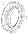
- FIG. 3 is an isometric view of an isometric view of a full ring turbine stator assembly, such as the stator assembly 220 of FIG. 2 , removed from a turbine section.
- FIG. 4 is a partial, sectional view of the stator assembly 220 of FIG. 3
- FIG. 5 is a top partial view of the stator assembly 220 of FIG. 4 in accordance with an exemplary embodiment.
- FIGS. 3-5 depict one exemplary embodiment, other exemplary embodiments may have alternate configurations or arrangements.
- FIGS. 4 and 5 depict a partial view circumferential slice or portion of a continuous full ring stator assembly 220. Alternatively, a number of separate partial segments may be circumferentially arranged to form the annular structure of the stator assembly 220.
- the stator assembly 220 includes stator vanes 224 (one shown in FIG. 4 ) extending radially between inner diameter end wall 226 and the outer diameter end wall 228.
- the stator vane 224 is formed by two side (or outer) walls 312, 314 each having outer surfaces that together define an airfoil shape. In a chordwise direction, the side walls 312, 314 are joined at a leading edge 316 and trailing edge 318.
- chordwise refers to a generally longitudinal dimension along the airfoil from leading edge to trailing edge, typically curved for air flow characteristics.
- the inner diameter end wall 226 may have an inner surface 322, an outer surface 324, a forward end 326, an aft end 328, and side edges 330, 332. As noted above, the outer surface 324 of the inner diameter end wall 226 partially defines a portion of the inner flow path boundary 212.
- the inner diameter end wall 226 further includes forward and aft rails 334, 336 extending in a radial direction from the inner surface 322 that facilitate mounting the stator assembly 220 in the turbine section 150.
- the outer diameter end wall 228 may have an inner surface 342, an outer surface 344, a forward end 346, an aft end 348, and side edges 350 (one of which is shown). As noted above, the inner surface 344 of the outer diameter end wall 228 partially defines a portion of the outer flow path boundary 214.
- the outer diameter end wall 228 further includes forward and aft rails 354, 356 extending radially outward from the outer surface 342 that facilitate mounting the stator assembly 220 in the turbine section 150.
- FIG. 5 is a top view of the stator assembly 220 that illustrates the outer diameter end wall 228, including forward and aft rails 354, 356 and forward and aft ends 346, 348.
- the forward and aft rails 354, 356 may facilitate the flow of cooling air to desired locations.
- Other rails may also be provided, including as one example, an airfoil rail 358 that extends from the outer surface 344 and generally outlines the stator vane 224.
- FIG. 3 additionally depicts baffles 254, 280, 281 discussed in greater detail below.
- cooling air may be delivered by various cooling circuits to portions of the turbine section 150.
- cooling air may be directed through internal cavities (not shown) in the rotor disk 246 and platform 244 to cool the rotor blades 242.
- cooling air may be directed through the outer diameter end wall 228 and into the stator vanes 224.
- the turbine section 150 further includes a cooling circuit to direct cooling air to a portion the outer diameter end wall 228 and then to the rotor shroud 248. Additional details about this cooling circuit within the turbine section 150 will be discussed below with reference to FIGS. 2-5 .
- the turbine section 150 may have one or more cavities or structures to direct cooling air to desired locations. Such cooling air may be obtained as bleed air from the compressor section 130.
- the turbine section 150 includes a first (or main) cavity 250 that receives cooling air 290.
- the first cavity 250 is at least partially defined by a first baffle 252 extending over the stator assembly 220 and a second baffle 254 at least partially extending over the rotor shroud 248.
- the first baffle 252 extends in an axial direction from the forward end 346 to the aft rail 356 to cover the stator assembly 220, while the second baffle 254 is coupled to the aft rail 356 and extends over at least a portion of the rotor shroud 248.
- a second cavity 260 is at least partially defined by the first baffle 252, the upper surface of the outer diameter end wall 228, the forward rail 354, and the aft rail 356.
- the second cavity 260 is fluidly coupled to the first cavity 250 by a first set of holes 264 formed within the first baffle 252.
- the holes 264 extend in a radial direction through the first baffle 252.
- the second cavity 260 may be considered to have one or more sub-cavities 261, 262, 263 at least partially defined, in some embodiments, by rails extending from the outer diameter end wall 228.
- the second cavity 260 may be considered to have a forward end sub-cavity 261 extending along the forward end 346, an airfoil sub-cavity 262 extending within the airfoil rail 358, and an aft sub-cavity 263 extending along the aft end 348.
- a third baffle 280 and a fourth baffle 281 are positioned to at least partially circumscribe the outer surface of the shroud 248.
- the fourth baffle 281 extends from the aft rail 356 and may include one or more flanges 283 to create mounting or attachment points for the second and third baffles 254, 280.
- the second baffle 254 extends from the aft rail 356 to the flange 283 of the fourth baffle 281, and the third baffle 280 extends from the aft rail 356 to the flange 283.
- Any arrangement of baffles 254, 280, 281 may be provided, and one or more of the baffles 254, 280, 281 may be integral with one another and/or with the stator assembly 220.
- the baffles 254, 280, 281 function to create one or more cavities 270, 284, 286, as described below.
- the third cavity 270 is at least partially defined by the aft rail 356, the third baffle 280, and the fourth baffle 281.
- the third cavity 270 may be fluidly coupled to the second cavity 260 by a second set of holes 272 formed in the aft rail 356 of the outer diameter end wall 228.
- Each hole 272 may extend in any suitable direction through the aft rail 356, including at least partially axial and at least partially radial, as depicted in FIG. 2 .
- the holes 272 may be arranged as a row of holes 272 that extends in a circumferential direction. In some embodiments, two or more rows may extend in a circumferential direction.
- the aft rail 356 may include a inter-cavity or void to receive the air flow through the holes 272 to impinge upon the aft rail.
- a seal is formed between the first baffle 252 and the aft rail 356 and between the second baffle 254 and the aft rail 356 such that the first cavity 250 is only fluidly coupled to the third cavity 270 through the second cavity 262, e.g., such that air does not leak directly between the first cavity 250 and the third cavity 270.
- the fourth cavity 284 is formed by the third baffle 280 and the fourth baffle 281.
- the fourth cavity 284 is fluidly to the third cavity 270 by the third set of holes 282 formed in the third baffle 280.
- the holes 282 extend in a generally radial direction through the third baffle 280.
- the third baffle 280 may form a seal with the aft rail 356 and the fourth baffle 281 such that the third cavity 270 is only fluidly coupled to the fourth cavity 284 through holes 282.
- the third baffle 280 may function to meter the cooling air between the fourth cavity 284 and the fifth cavity 286.
- the third baffle 280 may be omitted.
- the fifth cavity 286 is formed by the fourth baffle 281 and the shroud 248.
- the fifth cavity 286 is fluidly coupled to the fourth cavity 284 by a fourth set of holes 285 formed in the fourth baffle 281.
- the holes 285 extend in a radial direction through the fourth baffle 281.
- the fourth baffle 281 may form a seal with the aft rail 356 and/or the third baffle 280 such that the fourth cavity 284 is only fluidly coupled to the fifth cavity 286 through holes 285.
- any number, size, or arrangement of holes 285 (as well as holes 264, 272, 282) may be provided to obtain the desired flow characteristics.
- Computational fluid dynamics (CFD) analysis may be used to determine the number, orientation, dimension, and position of the holes 264, 272, 282, 285.
- Such holes 264, 272, 282, 285 may be formed, for example, using EDM machining.
- cooling air 290 flows through the first cavity 250 in a radially inward direction.
- the cooling air 290 flows through the holes 264 in the first baffle 252 into the second cavity 260 to cool the stator assembly 220.
- a portion 291 flows through sub-cavity 261 to cool the forward end 346 of the outer diameter end wall 228, another portion 292 flows through the sub-cavity 262 to cool the stator vane 224, and a further portion 293 flows through the sub-cavity 263 to cool the aft end 348 of the outer diameter end wall 228.
- FIG. 2 depicts the different air flow portions 291-293 as cooling different areas of the outer diameter end wall 228, in some embodiments, one or more portions 291-293 may be combined or omitted. In one embodiment, the sub-cavities 261-263 are fluidly isolated from one another.
- the cooling holes 264 are arranged such that the cooling air portion 293 impinges on the aft end 348.
- impinge or “impingement cooling” refers to a cooling flow striking the surface to be cooled at approximately 90° to enhance cooling effectiveness, particularly as compared to other types of cooling flows, such as film cooling.
- the portion of cooling air 293 that cools the aft end 348 of the outer diameter end wall 228 flows through the holes 272 formed in the aft rail 336 of the outer diameter end wall 228 into the third cavity 270.
- the cooling air 293 flows downstream through the holes 272 and then radially outward and downstream through the third cavity 270.
- the cooling air portion 293 subsequently flows radially inward through the holes 282 in the third baffle 280 into the fourth cavity 284. From the fourth cavity 284, the cooling air 293 flows radially inward through holes 285 into the fifth cavity 286. In the fifth cavity 286, the cooling air 293 cools the shroud 248.
- the cooling holes 285 are arranged such that the cooling air portion 293 impinges on the outer surface of the shroud 248.
- the cooling air cools the shroud 248 and flows out of the first cavity 286 through a space between the shroud 248 and the stator assembly 220. As such, the cooling air 293 that cools the aft end of the outer diameter end wall 228 is then used to cool the shroud 248.
- the same air flow portion 293 is used twice for sequential impingement cooling.
- the shroud cooling air flow 293 is "pre-used" to increase the effectiveness of the overall cooling flow. Since the shroud 248 typically operates at lower temperatures than the stator assembly 220, the increased temperature of the cooling air 293 from the stator assembly 220 is an acceptable trade-off, particularly considering the resulting ability to increase cooling of the stator assembly 220 and/or to reduce the overall volume of cooling air.
- the cooling circuit is provided to maintain the stator assembly 220 and rotor shroud 248 at suitable temperatures. Considerations may include engine application, required heat extraction, stress analysis, the temperature and pressure of the cooling air, and cooling effectiveness. Although not described in detail, the impingement cooling described above may be combined with other cooling techniques, including turbulence promoters and film cooling.
- Exemplary embodiments may minimize the amount of air necessary to cool the gas turbine engine and increase efficiency. Additionally, because of the relative simplicity of the design, the systems and methods disclosed herein can be readily incorporated on new design engines or it can be economically retrofitted on existing engines.
- the gas turbine engine assemblies produced according to exemplary embodiments may find beneficial use in many industries including aerospace, but also including industrial applications such as electricity generation, naval propulsion, pumping sets for gas and oil transmission, aircraft propulsion, automobile engines, and/or stationary power plants.
Abstract
Description
- This invention was made with Government support under Contract No. W911W6-08-2-0001 awarded by the US Army. The Government has certain rights in this invention.
- The present invention generally relates to gas turbine engines, and more particularly relates to turbine sections of gas turbine engines with improved cooling characteristics.
- A gas turbine engine may be used to power various types of vehicles and systems. A particular type of gas turbine engine that may be used to power aircraft is a turbofan gas turbine engine. A turbofan gas turbine engine conventionally includes, for example, five major sections: a fan section, a compressor section, a combustor section, a turbine section, and an exhaust section. The fan section is typically positioned at the inlet section of the engine and includes a fan that induces air from the surrounding environment into the engine and accelerates a fraction of this air toward the compressor section. The remaining fraction of air induced into the fan section is accelerated into and through a bypass plenum and out the exhaust section.
- The compressor section raises the pressure of the air it receives from the fan section, and the resulting compressed air then enters the combustor section, where a ring of fuel nozzles injects a steady stream of fuel into a combustion chamber formed between inner and outer liners. The fuel and air mixture is ignited to form combustion gases, which drive rotors in the turbine section for power extraction. In a typical configuration, the turbine section includes rows of stator vanes and rotor blades disposed in an alternating sequence along the axial length of a generally annular hot gas flow path. The rotor blades are mounted at the periphery of one or more rotor disks that are coupled to drive a main engine shaft. The gases then exit the engine at the exhaust section.
- In most gas turbine engine applications, it is desirable to regulate the operating temperature of certain engine components in order to prevent overheating and potential mechanical failures attributable thereto. Most turbine components, particularly those exposed to the high temperatures of the mainstream gas flow, may benefit from temperature management. Accordingly, in many turbine sections, the volumetric space disposed radially inwardly or outwardly from the hot gas flow path includes internal cavities through which cooling air flow is provided. The cooling of the turbine components attempts to maintain temperatures that are suitable for material and stress level.
- In many conventional engines, relatively high levels of cooling air flows have been used to obtain satisfactory temperature control of turbine components. However, it is generally desirable to employ mechanisms to minimize this cooling air since air from the compressor used for cooling is not available for combustion.
- Accordingly, it is desirable to provide gas turbine engines with turbine sections having improved thermal management. Furthermore, other desirable features and characteristics of the present invention will become apparent from the subsequent detailed description of the invention and the appended claims, taken in conjunction with the accompanying drawings and this background of the invention.
- In accordance with an exemplary embodiment, a turbine section of a gas turbine engine is provided. The turbine section includes a stator assembly comprising an inner diameter end wall, an outer diameter end wall, and a stator vane extending between the inner diameter end wall and the outer diameter end wall within a mainstream gas flow path; a turbine rotor assembly downstream of the stator assembly and including a rotor blade extending into the mainstream gas flow path; a housing including an annular shroud that circumscribes the rotor blade and at least partially defines the mainstream hot gas flow path; a first baffle arranged to define a first cavity with the outer diameter end wall of the stator assembly; a second baffle; and a third baffle arranged to define a second cavity with the second baffle and a third cavity with the shroud. The first cavity is fluidly coupled to the second cavity and the second cavity is fluidly coupled to the third cavity such that cooling air flows from the first cavity to the second cavity and from the second cavity to the third cavity.
- In accordance with an exemplary embodiment, a method is provided for cooling turbine components in a gas turbine engine. The method includes directing a flow of cooling air from a main cavity through a first set of holes in a first baffle into a first cavity to impinge an outer diameter end wall of a stator assembly; directing a first portion of the flow of cooling air through a second set of holes in an aft rail of the outer diameter end wall of the stator assembly into a second cavity; and directing the first portion of the flow of cooling air through a third set of holes in a second baffle into a third cavity to impinge a rotor shroud.
- The present invention will hereinafter be described in conjunction with the following drawing figures, wherein like numerals denote like elements, and wherein:
-
FIG. 1 is a partial cross-sectional view of a gas turbine engine in accordance with an exemplary embodiment; -
FIG. 2 is a partial cross-sectional elevation view of a turbine section of the gas turbine engine ofFIG. 1 in accordance with an exemplary embodiment; -
FIG. 3 is an isometric view of a full ring turbine stator assembly that may be incorporated into the turbine section ofFIG. 2 in accordance with an exemplary embodiment; -
FIG. 4 is a section of the turbine stator assembly ofFIG. 3 in accordance with an exemplary embodiment; and -
FIG. 5 is a top view of the turbine stator assembly ofFIG. 3 in accordance with an exemplary embodiment. - The following detailed description is merely exemplary in nature and is not intended to limit the invention or the application and uses of the invention. As used herein, the word "exemplary" means "serving as an example, instance, or illustration." Thus, any embodiment described herein as "exemplary" is not necessarily to be construed as preferred or advantageous over other embodiments. All of the embodiments described herein are exemplary embodiments provided to enable persons skilled in the art to make or use the invention and not to limit the scope of the invention which is defined by the claims. Furthermore, there is no intention to be bound by any theory presented in the preceding background or the following detailed description.
- Broadly, exemplary embodiments discussed herein include gas turbine engines with turbine sections that maintain suitable temperatures with improved efficiency. More particularly, exemplary turbine sections include a housing with baffles that direct cooling air onto the outer diameter end wall of the stator assembly and subsequently direct a portion of that air from the outer diameter end wall to the rotor shroud. In effect, the cooling air is pre-used (or reused) to cool two different areas, thereby enabling higher operating temperatures and/or a reduction in the amount of cooling air needed to maintain appropriate temperatures.
-
FIG. 1 is a cross-sectional view of agas turbine engine 100, according to an exemplary embodiment. In general, exemplary embodiments discussed herein may be applicable to any type of engines, including turboshaft engines. Thegas turbine engine 100 can form part of, for example, an auxiliary power unit for an aircraft or a propulsion system for an aircraft. Thegas turbine engine 100 has an overall construction and operation that is generally understood by persons skilled in the art. - As shown, the
engine 100 may be an annular structure about a longitudinal or axial centerline axis 102. In the description that follows, the term "axial" refers broadly to a direction parallel to the axis 102 about which the rotating components of theengine 100 rotate. This axis 102 runs from the front of theengine 100 to the back of theengine 100. The term "radial" refers broadly to a direction that is perpendicular to the axis 102 and that points towards or away from the axis of theengine 100. As used below, the terms "inner" and "outer" are relative terms in which "inner" is radially closer to the axis 102 than "outer". A "circumferential" direction at a given point is a direction that is normal to the local radial direction and normal to the axial direction. An "upstream" direction refers to the direction from which the local flow is coming, while a "downstream" direction refers to the direction in which the local flow is traveling. In the most general sense, flow through the engine tends to be from front to back, so the "upstream direction" will generally refer to a forward direction, while a "downstream direction" will refer to a rearward direction. - The
gas turbine engine 100 may be disposed in anengine case 110 and may include afan section 120, acompressor section 130, acombustion section 140, aturbine section 150, and anexhaust section 160. Thefan section 120 may include a fan, which draws in and accelerates air. A fraction of the accelerated air exhausted from thefan section 120 is directed through abypass section 170 to provide a forward thrust. The remaining fraction of air exhausted from the fan is directed into thecompressor section 130. - The
compressor section 130 may include a series of compressors that raise the pressure of the air directed into it from the fan. The compressors may direct the compressed air into thecombustion section 140. The compressors of thecompressor section 130 may also provide a portion of the compressed air as cooling air to other portions of theengine 100, as discussed below. In thecombustion section 140, the high pressure air is mixed with fuel and combusted. The combusted air is then directed into theturbine section 150. - As described in further detail below, the
turbine section 150 may include a series of rotor and stator assemblies disposed in axial flow series. The combusted air from thecombustion section 140 expands through the rotor and stator assemblies and drives the rotor assemblies to rotate a main engine shaft for energy extraction. As also discussed above, theturbine section 150 may have structures to improve the effectiveness of the cooling air from thecompressor section 130. The air is then exhausted through a propulsion nozzle disposed in theexhaust section 160 to provide additional forward thrust. -
FIG. 2 is a partial cross-sectional elevation view of aturbine section 150 of thegas turbine engine 100 ofFIG. 1 in accordance with an exemplary embodiment. The illustratedturbine section 150 may be part of a high pressure turbine or a low pressure turbine. Theturbine section 150 may have an overall construction and operation that is generally known and understood by persons skilled in the art. - In general terms, the
turbine section 150 includes amainstream flow path 210 defined in part by an annular innerflow path boundary 212 and an annular outerflow path boundary 214 that receives mainstreamhot gas flow 216 from the combustion section 140 (FIG. 1 ). In practice, the annular innerflow path boundary 212 and annular outerflow path boundary 214 are concentrically arranged to optimize aerodynamic and operational efficiency. - The
turbine section 150 includes an alternating sequence ofstator assemblies 220 androtor assemblies 240 arranged within a housing 202. In general terms, the housing 202 broadly refers to the components that house and support the stator androtor assemblies FIG. 2 , onestator assembly 220 and onerotor assembly 240 are shown. Although only onestator assembly 220 and onerotor assembly 240 are shown,such stator assemblies 220 androtor assemblies 240 are typically arranged in alternating axially spaced, circumferential rows. In general, any number of stator androtor assemblies hot gas flow 216 flows within theboundaries rotor assemblies - The
stator assembly 220 is formed by a circumferential row of stator vanes (or airfoils) 224 (one of which is shown) extending radially between from an inner diameter end wall (or platform) 226 and an outer diameter end wall (or platform) 228. Theend walls turbine section 150 to form a portion of themainstream flow path 210. As described in greater detail below, the innerdiameter end wall 226 and outerdiameter end wall 228 may be continuous rings or arcuate segments arranged to form the innerflow path boundary 212 and annular outerflow path boundary 214, respectively, of theflow path 210. - The
rotor assembly 240 is formed by a circumferential row of rotor blades 242 (one of which is shown) projecting radially outwardly from acircumferential rotor platform 244 mounted on the periphery of arotor disk 246, which in turn circumscribes a main engine shaft (not shown). The housing 202 includes ashroud 248 surrounding therotor assembly 240 to form a portion of the outerflow path boundary 214. Theshroud 248 axially extends at least between the leading and trailing edges of therotor blade 242, typically in close radial proximity to therotor blade 242. During operation, the mainstreamhot gas flow 216 drives therotor blades 242 and the associatedrotor assembly 240 for power extraction, while thestator assemblies 220 are generally stationary. - To allow the
turbine section 150 to operate at desirable elevated temperatures, certain components are cooled with air typically bled from the compressor section 130 (FIG. 1 ). In particular, details about cooling the outerdiameter end wall 228 of thestator assembly 220 and therotor shroud 248 will be provided below after a brief discussion ofFIGS. 3-5 , which provide additional details about thestator assembly 220. -
FIG. 3 is an isometric view of an isometric view of a full ring turbine stator assembly, such as thestator assembly 220 ofFIG. 2 , removed from a turbine section.FIG. 4 is a partial, sectional view of thestator assembly 220 ofFIG. 3 , andFIG. 5 is a top partial view of thestator assembly 220 ofFIG. 4 in accordance with an exemplary embodiment. AlthoughFIGS. 3-5 depict one exemplary embodiment, other exemplary embodiments may have alternate configurations or arrangements.FIGS. 4 and5 depict a partial view circumferential slice or portion of a continuous fullring stator assembly 220. Alternatively, a number of separate partial segments may be circumferentially arranged to form the annular structure of thestator assembly 220. - Referring to
FIGS. 4 and5 , as introduced above, thestator assembly 220 includes stator vanes 224 (one shown inFIG. 4 ) extending radially between innerdiameter end wall 226 and the outerdiameter end wall 228. Generally, thestator vane 224 is formed by two side (or outer)walls side walls leading edge 316 and trailingedge 318. As used herein, the term "chordwise" refers to a generally longitudinal dimension along the airfoil from leading edge to trailing edge, typically curved for air flow characteristics. - The inner
diameter end wall 226 may have aninner surface 322, anouter surface 324, aforward end 326, anaft end 328, and side edges 330, 332. As noted above, theouter surface 324 of the innerdiameter end wall 226 partially defines a portion of the innerflow path boundary 212. The innerdiameter end wall 226 further includes forward andaft rails inner surface 322 that facilitate mounting thestator assembly 220 in theturbine section 150. - The outer
diameter end wall 228 may have aninner surface 342, anouter surface 344, aforward end 346, anaft end 348, and side edges 350 (one of which is shown). As noted above, theinner surface 344 of the outerdiameter end wall 228 partially defines a portion of the outerflow path boundary 214. The outerdiameter end wall 228 further includes forward andaft rails outer surface 342 that facilitate mounting thestator assembly 220 in theturbine section 150. As introduced above,FIG. 5 is a top view of thestator assembly 220 that illustrates the outerdiameter end wall 228, including forward andaft rails aft rails airfoil rail 358 that extends from theouter surface 344 and generally outlines thestator vane 224. Although not shown inFIG. 4 ,FIG. 3 additionally depictsbaffles - As described in greater detail below, cooling air may be delivered by various cooling circuits to portions of the
turbine section 150. As examples, cooling air may be directed through internal cavities (not shown) in therotor disk 246 andplatform 244 to cool therotor blades 242. Similarly, cooling air may be directed through the outerdiameter end wall 228 and into the stator vanes 224. In accordance with exemplary embodiments, theturbine section 150 further includes a cooling circuit to direct cooling air to a portion the outerdiameter end wall 228 and then to therotor shroud 248. Additional details about this cooling circuit within theturbine section 150 will be discussed below with reference toFIGS. 2-5 . - As introduced above, the
turbine section 150 may have one or more cavities or structures to direct cooling air to desired locations. Such cooling air may be obtained as bleed air from thecompressor section 130. Referring again toFIG. 2 , theturbine section 150 includes a first (or main)cavity 250 that receives coolingair 290. Thefirst cavity 250 is at least partially defined by afirst baffle 252 extending over thestator assembly 220 and asecond baffle 254 at least partially extending over therotor shroud 248. Thefirst baffle 252 extends in an axial direction from theforward end 346 to theaft rail 356 to cover thestator assembly 220, while thesecond baffle 254 is coupled to theaft rail 356 and extends over at least a portion of therotor shroud 248. - A
second cavity 260 is at least partially defined by thefirst baffle 252, the upper surface of the outerdiameter end wall 228, theforward rail 354, and theaft rail 356. Thesecond cavity 260 is fluidly coupled to thefirst cavity 250 by a first set ofholes 264 formed within thefirst baffle 252. Theholes 264 extend in a radial direction through thefirst baffle 252. Thesecond cavity 260 may be considered to have one or more sub-cavities 261, 262, 263 at least partially defined, in some embodiments, by rails extending from the outerdiameter end wall 228. As examples, thesecond cavity 260 may be considered to have a forward end sub-cavity 261 extending along theforward end 346, anairfoil sub-cavity 262 extending within theairfoil rail 358, and anaft sub-cavity 263 extending along theaft end 348. - A
third baffle 280 and afourth baffle 281 are positioned to at least partially circumscribe the outer surface of theshroud 248. Thefourth baffle 281 extends from theaft rail 356 and may include one ormore flanges 283 to create mounting or attachment points for the second andthird baffles second baffle 254 extends from theaft rail 356 to theflange 283 of thefourth baffle 281, and thethird baffle 280 extends from theaft rail 356 to theflange 283. Any arrangement ofbaffles baffles stator assembly 220. Thebaffles more cavities - The
third cavity 270 is at least partially defined by theaft rail 356, thethird baffle 280, and thefourth baffle 281. Thethird cavity 270 may be fluidly coupled to thesecond cavity 260 by a second set ofholes 272 formed in theaft rail 356 of the outerdiameter end wall 228. Eachhole 272 may extend in any suitable direction through theaft rail 356, including at least partially axial and at least partially radial, as depicted inFIG. 2 . Generally, theholes 272 may be arranged as a row ofholes 272 that extends in a circumferential direction. In some embodiments, two or more rows may extend in a circumferential direction. As also shown, theaft rail 356 may include a inter-cavity or void to receive the air flow through theholes 272 to impinge upon the aft rail. Generally, a seal is formed between thefirst baffle 252 and theaft rail 356 and between thesecond baffle 254 and theaft rail 356 such that thefirst cavity 250 is only fluidly coupled to thethird cavity 270 through thesecond cavity 262, e.g., such that air does not leak directly between thefirst cavity 250 and thethird cavity 270. - The
fourth cavity 284 is formed by thethird baffle 280 and thefourth baffle 281. Thefourth cavity 284 is fluidly to thethird cavity 270 by the third set ofholes 282 formed in thethird baffle 280. Theholes 282 extend in a generally radial direction through thethird baffle 280. Thethird baffle 280 may form a seal with theaft rail 356 and thefourth baffle 281 such that thethird cavity 270 is only fluidly coupled to thefourth cavity 284 throughholes 282. Thethird baffle 280 may function to meter the cooling air between thefourth cavity 284 and thefifth cavity 286. In some embodiments, thethird baffle 280 may be omitted. - The
fifth cavity 286 is formed by thefourth baffle 281 and theshroud 248. Thefifth cavity 286 is fluidly coupled to thefourth cavity 284 by a fourth set ofholes 285 formed in thefourth baffle 281. Theholes 285 extend in a radial direction through thefourth baffle 281. Thefourth baffle 281 may form a seal with theaft rail 356 and/or thethird baffle 280 such that thefourth cavity 284 is only fluidly coupled to thefifth cavity 286 throughholes 285. Generally, any number, size, or arrangement of holes 285 (as well asholes holes Such holes - As such, the cooling circuit formed the
various cavities air 290 flows through thefirst cavity 250 in a radially inward direction. The coolingair 290 flows through theholes 264 in thefirst baffle 252 into thesecond cavity 260 to cool thestator assembly 220. In particular, aportion 291 flows through sub-cavity 261 to cool theforward end 346 of the outerdiameter end wall 228, anotherportion 292 flows through the sub-cavity 262 to cool thestator vane 224, and afurther portion 293 flows through the sub-cavity 263 to cool theaft end 348 of the outerdiameter end wall 228. AlthoughFIG. 2 depicts the different air flow portions 291-293 as cooling different areas of the outerdiameter end wall 228, in some embodiments, one or more portions 291-293 may be combined or omitted. In one embodiment, the sub-cavities 261-263 are fluidly isolated from one another. - In any event, the cooling holes 264 are arranged such that the cooling
air portion 293 impinges on theaft end 348. As used herein the term "impinge" or "impingement cooling" refers to a cooling flow striking the surface to be cooled at approximately 90° to enhance cooling effectiveness, particularly as compared to other types of cooling flows, such as film cooling. The portion of coolingair 293 that cools theaft end 348 of the outerdiameter end wall 228 flows through theholes 272 formed in theaft rail 336 of the outerdiameter end wall 228 into thethird cavity 270. In the depicted embodiment, the coolingair 293 flows downstream through theholes 272 and then radially outward and downstream through thethird cavity 270. The coolingair portion 293 subsequently flows radially inward through theholes 282 in thethird baffle 280 into thefourth cavity 284. From thefourth cavity 284, the coolingair 293 flows radially inward throughholes 285 into thefifth cavity 286. In thefifth cavity 286, the coolingair 293 cools theshroud 248. Typically, the cooling holes 285 are arranged such that the coolingair portion 293 impinges on the outer surface of theshroud 248. The cooling air cools theshroud 248 and flows out of thefirst cavity 286 through a space between theshroud 248 and thestator assembly 220. As such, the coolingair 293 that cools the aft end of the outerdiameter end wall 228 is then used to cool theshroud 248. This enables a more efficient use of the collective base of coolingair 290 incavity 250 rather than separating the cooling air into multiple flows upstream of thestator assembly 220. The sameair flow portion 293 is used twice for sequential impingement cooling. In effect, the shroudcooling air flow 293 is "pre-used" to increase the effectiveness of the overall cooling flow. Since theshroud 248 typically operates at lower temperatures than thestator assembly 220, the increased temperature of the coolingair 293 from thestator assembly 220 is an acceptable trade-off, particularly considering the resulting ability to increase cooling of thestator assembly 220 and/or to reduce the overall volume of cooling air. - In general, design of the baffles, holes, and cavities may depend on various factors, including application and engine design. In one exemplary embodiment, the cooling circuit is provided to maintain the
stator assembly 220 androtor shroud 248 at suitable temperatures. Considerations may include engine application, required heat extraction, stress analysis, the temperature and pressure of the cooling air, and cooling effectiveness. Although not described in detail, the impingement cooling described above may be combined with other cooling techniques, including turbulence promoters and film cooling. - Exemplary embodiments may minimize the amount of air necessary to cool the gas turbine engine and increase efficiency. Additionally, because of the relative simplicity of the design, the systems and methods disclosed herein can be readily incorporated on new design engines or it can be economically retrofitted on existing engines. The gas turbine engine assemblies produced according to exemplary embodiments may find beneficial use in many industries including aerospace, but also including industrial applications such as electricity generation, naval propulsion, pumping sets for gas and oil transmission, aircraft propulsion, automobile engines, and/or stationary power plants.
- While at least one exemplary embodiment has been presented in the foregoing detailed description of the invention, it should be appreciated that a vast number of variations exist. It should also be appreciated that the exemplary embodiment or exemplary embodiments are only examples, and are not intended to limit the scope, applicability, or configuration of the invention in any way. Rather, the foregoing detailed description will provide those skilled in the art with a convenient road map for implementing an exemplary embodiment of the invention. It being understood that various changes may be made in the function and arrangement of elements described in an exemplary embodiment without departing from the scope of the invention as set forth in the appended claims.
Claims (10)
- A turbine section (150) of a gas turbine engine (100), comprising:a stator assembly (220) comprising an inner diameter end wall (226), an outer diameter end wall (228), and a stator vane (224) extending between the inner diameter end wall (226) and the outer diameter end wall (228) within a mainstream gas flow path (210);a turbine rotor assembly (240) downstream of the stator assembly (220) and including a rotor blade (242) extending into the mainstream gas flow path (210);a housing (202) including an annular shroud (248) that circumscribes the rotor blade (242) and at least partially defines the mainstream hot gas flow path (210);a first baffle (252) arranged to define a first cavity (260) with the outer diameter end wall (228) of the stator assembly (220);a second baffle (254); anda third baffle (281) arranged to define a second cavity (270) with the second baffle (254) and a third cavity (286) with the shroud (248), wherein the first cavity (260) is fluidly coupled to the second cavity (270) and the second cavity (270) is fluidly coupled to the third cavity (286) such that cooling air (290) flows from the first cavity (260) to the second cavity (270) and from the second cavity (270) to the third cavity (286).
- The turbine section (150) of claim 1, wherein the first baffle (252) includes a first set of holes (264) configured to direct a first portion (291, 292, 293) of cooling air (290) to impinge on the outer diameter end wall (228).
- The turbine section (150) of claim 2, wherein the stator assembly (220) includes a second set of holes (272) configured to direct the first portion (293) of cooling air (290) into the second cavity (270).
- The turbine section (150) of claim 3, wherein the third baffle (281) includes a third set of holes (285) configured to direct the first portion (293) of cooling air (290) into the third cavity (286) to impinge on the shroud (248).
- The turbine section (150) of claim 4, wherein the third set of holes (285) is configured to direct the first portion (293) of cooling air (290) into the third cavity (286) and onto a radially outer surface of the shroud (248).
- The turbine section (150) of claim 5, further comprising a fourth baffle (280) within the second cavity (270).
- The turbine section (150) of claim 5, further comprising a main cavity (250) supplying the cooling air (290) to the first cavity (260), and wherein the second baffle (254) forms a seal to block the cooling air (290) from flowing directly from the main cavity (250) into the second cavity (270).
- The turbine section (150) of claim 7, wherein the stator assembly (220) includes an aft rail (356) extending radially from the outer diameter end wall (228) to the first baffle (252).
- The turbine section (150) of claim 8, wherein the aft rail (356) defines a second set of cooling holes (282) to fluidly couple the first cavity (260) to the second cavity (270).
- The turbine section (150) of claim 9, wherein the first baffle (252) is configured to direct the first portion (231) of cooling air (290) to impinge on an aft end (348) of the outer diameter end wall (228), and
wherein the first cavity (260) is formed by a first sub-cavity (261) proximate to a leading edge of the outer diameter end wall (228), a second sub-cavity (262) proximate to the stator vane (224), and a third sub-cavity (263) proximate to the aft end (348) of the outer diameter end wall (228), wherein the first, second, and third sub-cavities (261, 262, 263) are fluidly isolated from one another.
Applications Claiming Priority (1)
| Application Number | Priority Date | Filing Date | Title |
|---|---|---|---|
| US14/227,924 US9657642B2 (en) | 2014-03-27 | 2014-03-27 | Turbine sections of gas turbine engines with dual use of cooling air |
Publications (2)
| Publication Number | Publication Date |
|---|---|
| EP2924238A1 true EP2924238A1 (en) | 2015-09-30 |
| EP2924238B1 EP2924238B1 (en) | 2019-05-15 |
Family
ID=52396486
Family Applications (1)
| Application Number | Title | Priority Date | Filing Date |
|---|---|---|---|
| EP15151704.2A Active EP2924238B1 (en) | 2014-03-27 | 2015-01-19 | Turbine sections of gas turbine engines with dual use of cooling air |
Country Status (2)
| Country | Link |
|---|---|
| US (1) | US9657642B2 (en) |
| EP (1) | EP2924238B1 (en) |
Cited By (2)
| Publication number | Priority date | Publication date | Assignee | Title |
|---|---|---|---|---|
| CN107035428A (en) * | 2017-06-09 | 2017-08-11 | 中国航发湖南动力机械研究所 | Turborotor and its heat exchange structure |
| US9995157B2 (en) | 2014-04-04 | 2018-06-12 | United Technologies Corporation | Gas turbine engine turbine vane platform cooling |
Families Citing this family (8)
| Publication number | Priority date | Publication date | Assignee | Title |
|---|---|---|---|---|
| US10690055B2 (en) * | 2014-05-29 | 2020-06-23 | General Electric Company | Engine components with impingement cooling features |
| US9689276B2 (en) * | 2014-07-18 | 2017-06-27 | Pratt & Whitney Canada Corp. | Annular ring assembly for shroud cooling |
| US20160123186A1 (en) * | 2014-10-31 | 2016-05-05 | General Electric Company | Shroud assembly for a turbine engine |
| US10677084B2 (en) | 2017-06-16 | 2020-06-09 | Honeywell International Inc. | Turbine tip shroud assembly with plural shroud segments having inter-segment seal arrangement |
| US10900378B2 (en) | 2017-06-16 | 2021-01-26 | Honeywell International Inc. | Turbine tip shroud assembly with plural shroud segments having internal cooling passages |
| EP4001593B1 (en) * | 2020-11-13 | 2023-12-20 | Doosan Enerbility Co., Ltd. | A gas turbine vane comprising an impingement cooled inner shroud |
| JPWO2022202510A1 (en) * | 2021-03-23 | 2022-09-29 | ||
| US11808176B2 (en) | 2021-05-04 | 2023-11-07 | Rtx Corporation | CMC vane sealing arrangement |
Citations (3)
| Publication number | Priority date | Publication date | Assignee | Title |
|---|---|---|---|---|
| US4157232A (en) * | 1977-10-31 | 1979-06-05 | General Electric Company | Turbine shroud support |
| EP0515130A1 (en) * | 1991-05-20 | 1992-11-25 | General Electric Company | Tapered metering channel for cooling of gas turbine shroud |
| EP1533478A2 (en) * | 2003-11-24 | 2005-05-25 | General Electric Company | Turbine shroud asymmetrical cooling elements |
Family Cites Families (13)
| Publication number | Priority date | Publication date | Assignee | Title |
|---|---|---|---|---|
| NL45879C (en) | 1935-03-13 | |||
| GB753633A (en) | 1954-06-29 | 1956-07-25 | Westinghouse Electric Int Co | Improvements in or relating to turbines, particularly gas turbines |
| US4526226A (en) | 1981-08-31 | 1985-07-02 | General Electric Company | Multiple-impingement cooled structure |
| US4643250A (en) | 1985-07-01 | 1987-02-17 | Sundstrand Corporation | Fluid jet impingement heat exchanger for operation in zero gravity conditions |
| US5584651A (en) | 1994-10-31 | 1996-12-17 | General Electric Company | Cooled shroud |
| US6174134B1 (en) | 1999-03-05 | 2001-01-16 | General Electric Company | Multiple impingement airfoil cooling |
| US6779597B2 (en) | 2002-01-16 | 2004-08-24 | General Electric Company | Multiple impingement cooled structure |
| GB0405322D0 (en) | 2004-03-10 | 2004-04-21 | Rolls Royce Plc | Impingement cooling arrangement |
| US7097418B2 (en) | 2004-06-18 | 2006-08-29 | Pratt & Whitney Canada Corp. | Double impingement vane platform cooling |
| US8137056B2 (en) | 2006-03-02 | 2012-03-20 | Ihi Corporation | Impingement cooled structure |
| US7665953B2 (en) | 2006-11-30 | 2010-02-23 | General Electric Company | Methods and system for recuperated cooling of integral turbine nozzle and shroud assemblies |
| US8943832B2 (en) | 2011-10-26 | 2015-02-03 | General Electric Company | Fuel nozzle assembly for use in turbine engines and methods of assembling same |
| US8438851B1 (en) | 2012-01-03 | 2013-05-14 | General Electric Company | Combustor assembly for use in a turbine engine and methods of assembling same |
-
2014
- 2014-03-27 US US14/227,924 patent/US9657642B2/en not_active Expired - Fee Related
-
2015
- 2015-01-19 EP EP15151704.2A patent/EP2924238B1/en active Active
Patent Citations (3)
| Publication number | Priority date | Publication date | Assignee | Title |
|---|---|---|---|---|
| US4157232A (en) * | 1977-10-31 | 1979-06-05 | General Electric Company | Turbine shroud support |
| EP0515130A1 (en) * | 1991-05-20 | 1992-11-25 | General Electric Company | Tapered metering channel for cooling of gas turbine shroud |
| EP1533478A2 (en) * | 2003-11-24 | 2005-05-25 | General Electric Company | Turbine shroud asymmetrical cooling elements |
Cited By (3)
| Publication number | Priority date | Publication date | Assignee | Title |
|---|---|---|---|---|
| US9995157B2 (en) | 2014-04-04 | 2018-06-12 | United Technologies Corporation | Gas turbine engine turbine vane platform cooling |
| EP2927430B1 (en) * | 2014-04-04 | 2019-08-07 | United Technologies Corporation | Stator vane with a cooled platform for a gas turbine engine |
| CN107035428A (en) * | 2017-06-09 | 2017-08-11 | 中国航发湖南动力机械研究所 | Turborotor and its heat exchange structure |
Also Published As
| Publication number | Publication date |
|---|---|
| EP2924238B1 (en) | 2019-05-15 |
| US20150275763A1 (en) | 2015-10-01 |
| US9657642B2 (en) | 2017-05-23 |
Similar Documents
| Publication | Publication Date | Title |
|---|---|---|
| EP2924238B1 (en) | Turbine sections of gas turbine engines with dual use of cooling air | |
| EP2584142B1 (en) | Gas turbine engine cooling systems having hub-bleed impellers | |
| US9879544B2 (en) | Turbine rotor blades with improved tip portion cooling holes | |
| EP2851511A2 (en) | Turbine blades with tip portions having converging cooling holes | |
| US8616832B2 (en) | Turbine assemblies with impingement cooling | |
| US11035237B2 (en) | Blade with tip rail cooling | |
| US8882461B2 (en) | Gas turbine engines with improved trailing edge cooling arrangements | |
| EP3640432B1 (en) | Turbine shroud assemblies for gas turbine engines | |
| US10753207B2 (en) | Airfoil with tip rail cooling | |
| US10815806B2 (en) | Engine component with insert | |
| US10451084B2 (en) | Gas turbine engine with vane having a cooling inlet | |
| EP2551458A2 (en) | Blade Cooling and Sealing System | |
| EP3415719B1 (en) | Turbomachine blade cooling structure | |
| US9816389B2 (en) | Turbine rotor blades with tip portion parapet wall cavities | |
| US10280793B2 (en) | Insert and standoff design for a gas turbine engine vane | |
| EP3418496A2 (en) | A rotor blade for a turbomachine | |
| US10590777B2 (en) | Turbomachine rotor blade | |
| US10577945B2 (en) | Turbomachine rotor blade | |
| US20190003320A1 (en) | Turbomachine rotor blade | |
| CN114251132A (en) | Gas turbine engine rotor blade with metallic structural member and composite fairing |
Legal Events
| Date | Code | Title | Description |
|---|---|---|---|
| PUAI | Public reference made under article 153(3) epc to a published international application that has entered the european phase |
Free format text: ORIGINAL CODE: 0009012 |
|
| 17P | Request for examination filed |
Effective date: 20150119 |
|
| AK | Designated contracting states |
Kind code of ref document: A1 Designated state(s): AL AT BE BG CH CY CZ DE DK EE ES FI FR GB GR HR HU IE IS IT LI LT LU LV MC MK MT NL NO PL PT RO RS SE SI SK SM TR |
|
| AX | Request for extension of the european patent |
Extension state: BA ME |
|
| RAP1 | Party data changed (applicant data changed or rights of an application transferred) |
Owner name: HONEYWELL INTERNATIONAL INC. |
|
| STAA | Information on the status of an ep patent application or granted ep patent |
Free format text: STATUS: EXAMINATION IS IN PROGRESS |
|
| 17Q | First examination report despatched |
Effective date: 20180622 |
|
| GRAP | Despatch of communication of intention to grant a patent |
Free format text: ORIGINAL CODE: EPIDOSNIGR1 |
|
| STAA | Information on the status of an ep patent application or granted ep patent |
Free format text: STATUS: GRANT OF PATENT IS INTENDED |
|
| INTG | Intention to grant announced |
Effective date: 20190102 |
|
| RIN1 | Information on inventor provided before grant (corrected) |
Inventor name: GINTERT, JOHN Inventor name: CROSATTI, LORENZO Inventor name: RANA, RAJIV Inventor name: KANJIYANI, SHEZAN Inventor name: ZURMEHLY, ED Inventor name: TUCKER, BRADLEY REED |
|
| GRAS | Grant fee paid |
Free format text: ORIGINAL CODE: EPIDOSNIGR3 |
|
| GRAA | (expected) grant |
Free format text: ORIGINAL CODE: 0009210 |
|
| STAA | Information on the status of an ep patent application or granted ep patent |
Free format text: STATUS: THE PATENT HAS BEEN GRANTED |
|
| AK | Designated contracting states |
Kind code of ref document: B1 Designated state(s): AL AT BE BG CH CY CZ DE DK EE ES FI FR GB GR HR HU IE IS IT LI LT LU LV MC MK MT NL NO PL PT RO RS SE SI SK SM TR |
|
| REG | Reference to a national code |
Ref country code: CH Ref legal event code: EP |
|
| REG | Reference to a national code |
Ref country code: DE Ref legal event code: R096 Ref document number: 602015030194 Country of ref document: DE |
|
| REG | Reference to a national code |
Ref country code: IE Ref legal event code: FG4D |
|
| REG | Reference to a national code |
Ref country code: NL Ref legal event code: MP Effective date: 20190515 |
|
| REG | Reference to a national code |
Ref country code: LT Ref legal event code: MG4D |
|
| PG25 | Lapsed in a contracting state [announced via postgrant information from national office to epo] |
Ref country code: SE Free format text: LAPSE BECAUSE OF FAILURE TO SUBMIT A TRANSLATION OF THE DESCRIPTION OR TO PAY THE FEE WITHIN THE PRESCRIBED TIME-LIMIT Effective date: 20190515 Ref country code: NL Free format text: LAPSE BECAUSE OF FAILURE TO SUBMIT A TRANSLATION OF THE DESCRIPTION OR TO PAY THE FEE WITHIN THE PRESCRIBED TIME-LIMIT Effective date: 20190515 Ref country code: HR Free format text: LAPSE BECAUSE OF FAILURE TO SUBMIT A TRANSLATION OF THE DESCRIPTION OR TO PAY THE FEE WITHIN THE PRESCRIBED TIME-LIMIT Effective date: 20190515 Ref country code: PT Free format text: LAPSE BECAUSE OF FAILURE TO SUBMIT A TRANSLATION OF THE DESCRIPTION OR TO PAY THE FEE WITHIN THE PRESCRIBED TIME-LIMIT Effective date: 20190915 Ref country code: AL Free format text: LAPSE BECAUSE OF FAILURE TO SUBMIT A TRANSLATION OF THE DESCRIPTION OR TO PAY THE FEE WITHIN THE PRESCRIBED TIME-LIMIT Effective date: 20190515 Ref country code: FI Free format text: LAPSE BECAUSE OF FAILURE TO SUBMIT A TRANSLATION OF THE DESCRIPTION OR TO PAY THE FEE WITHIN THE PRESCRIBED TIME-LIMIT Effective date: 20190515 Ref country code: NO Free format text: LAPSE BECAUSE OF FAILURE TO SUBMIT A TRANSLATION OF THE DESCRIPTION OR TO PAY THE FEE WITHIN THE PRESCRIBED TIME-LIMIT Effective date: 20190815 Ref country code: LT Free format text: LAPSE BECAUSE OF FAILURE TO SUBMIT A TRANSLATION OF THE DESCRIPTION OR TO PAY THE FEE WITHIN THE PRESCRIBED TIME-LIMIT Effective date: 20190515 Ref country code: ES Free format text: LAPSE BECAUSE OF FAILURE TO SUBMIT A TRANSLATION OF THE DESCRIPTION OR TO PAY THE FEE WITHIN THE PRESCRIBED TIME-LIMIT Effective date: 20190515 |
|
| PG25 | Lapsed in a contracting state [announced via postgrant information from national office to epo] |
Ref country code: GR Free format text: LAPSE BECAUSE OF FAILURE TO SUBMIT A TRANSLATION OF THE DESCRIPTION OR TO PAY THE FEE WITHIN THE PRESCRIBED TIME-LIMIT Effective date: 20190816 Ref country code: RS Free format text: LAPSE BECAUSE OF FAILURE TO SUBMIT A TRANSLATION OF THE DESCRIPTION OR TO PAY THE FEE WITHIN THE PRESCRIBED TIME-LIMIT Effective date: 20190515 Ref country code: BG Free format text: LAPSE BECAUSE OF FAILURE TO SUBMIT A TRANSLATION OF THE DESCRIPTION OR TO PAY THE FEE WITHIN THE PRESCRIBED TIME-LIMIT Effective date: 20190815 Ref country code: LV Free format text: LAPSE BECAUSE OF FAILURE TO SUBMIT A TRANSLATION OF THE DESCRIPTION OR TO PAY THE FEE WITHIN THE PRESCRIBED TIME-LIMIT Effective date: 20190515 |
|
| REG | Reference to a national code |
Ref country code: AT Ref legal event code: MK05 Ref document number: 1133671 Country of ref document: AT Kind code of ref document: T Effective date: 20190515 |
|
| PG25 | Lapsed in a contracting state [announced via postgrant information from national office to epo] |
Ref country code: DK Free format text: LAPSE BECAUSE OF FAILURE TO SUBMIT A TRANSLATION OF THE DESCRIPTION OR TO PAY THE FEE WITHIN THE PRESCRIBED TIME-LIMIT Effective date: 20190515 Ref country code: AT Free format text: LAPSE BECAUSE OF FAILURE TO SUBMIT A TRANSLATION OF THE DESCRIPTION OR TO PAY THE FEE WITHIN THE PRESCRIBED TIME-LIMIT Effective date: 20190515 Ref country code: EE Free format text: LAPSE BECAUSE OF FAILURE TO SUBMIT A TRANSLATION OF THE DESCRIPTION OR TO PAY THE FEE WITHIN THE PRESCRIBED TIME-LIMIT Effective date: 20190515 Ref country code: CZ Free format text: LAPSE BECAUSE OF FAILURE TO SUBMIT A TRANSLATION OF THE DESCRIPTION OR TO PAY THE FEE WITHIN THE PRESCRIBED TIME-LIMIT Effective date: 20190515 Ref country code: RO Free format text: LAPSE BECAUSE OF FAILURE TO SUBMIT A TRANSLATION OF THE DESCRIPTION OR TO PAY THE FEE WITHIN THE PRESCRIBED TIME-LIMIT Effective date: 20190515 Ref country code: SK Free format text: LAPSE BECAUSE OF FAILURE TO SUBMIT A TRANSLATION OF THE DESCRIPTION OR TO PAY THE FEE WITHIN THE PRESCRIBED TIME-LIMIT Effective date: 20190515 |
|
| REG | Reference to a national code |
Ref country code: DE Ref legal event code: R097 Ref document number: 602015030194 Country of ref document: DE |
|
| PG25 | Lapsed in a contracting state [announced via postgrant information from national office to epo] |
Ref country code: SM Free format text: LAPSE BECAUSE OF FAILURE TO SUBMIT A TRANSLATION OF THE DESCRIPTION OR TO PAY THE FEE WITHIN THE PRESCRIBED TIME-LIMIT Effective date: 20190515 Ref country code: IT Free format text: LAPSE BECAUSE OF FAILURE TO SUBMIT A TRANSLATION OF THE DESCRIPTION OR TO PAY THE FEE WITHIN THE PRESCRIBED TIME-LIMIT Effective date: 20190515 |
|
| PLBE | No opposition filed within time limit |
Free format text: ORIGINAL CODE: 0009261 |
|
| STAA | Information on the status of an ep patent application or granted ep patent |
Free format text: STATUS: NO OPPOSITION FILED WITHIN TIME LIMIT |
|
| PG25 | Lapsed in a contracting state [announced via postgrant information from national office to epo] |
Ref country code: TR Free format text: LAPSE BECAUSE OF FAILURE TO SUBMIT A TRANSLATION OF THE DESCRIPTION OR TO PAY THE FEE WITHIN THE PRESCRIBED TIME-LIMIT Effective date: 20190515 |
|
| 26N | No opposition filed |
Effective date: 20200218 |
|
| PG25 | Lapsed in a contracting state [announced via postgrant information from national office to epo] |
Ref country code: PL Free format text: LAPSE BECAUSE OF FAILURE TO SUBMIT A TRANSLATION OF THE DESCRIPTION OR TO PAY THE FEE WITHIN THE PRESCRIBED TIME-LIMIT Effective date: 20190515 |
|
| PG25 | Lapsed in a contracting state [announced via postgrant information from national office to epo] |
Ref country code: SI Free format text: LAPSE BECAUSE OF FAILURE TO SUBMIT A TRANSLATION OF THE DESCRIPTION OR TO PAY THE FEE WITHIN THE PRESCRIBED TIME-LIMIT Effective date: 20190515 |
|
| REG | Reference to a national code |
Ref country code: DE Ref legal event code: R119 Ref document number: 602015030194 Country of ref document: DE |
|
| PG25 | Lapsed in a contracting state [announced via postgrant information from national office to epo] |
Ref country code: MC Free format text: LAPSE BECAUSE OF FAILURE TO SUBMIT A TRANSLATION OF THE DESCRIPTION OR TO PAY THE FEE WITHIN THE PRESCRIBED TIME-LIMIT Effective date: 20190515 |
|
| REG | Reference to a national code |
Ref country code: CH Ref legal event code: PL |
|
| GBPC | Gb: european patent ceased through non-payment of renewal fee |
Effective date: 20200119 |
|
| REG | Reference to a national code |
Ref country code: BE Ref legal event code: MM Effective date: 20200131 |
|
| PG25 | Lapsed in a contracting state [announced via postgrant information from national office to epo] |
Ref country code: DE Free format text: LAPSE BECAUSE OF NON-PAYMENT OF DUE FEES Effective date: 20200801 Ref country code: GB Free format text: LAPSE BECAUSE OF NON-PAYMENT OF DUE FEES Effective date: 20200119 Ref country code: LU Free format text: LAPSE BECAUSE OF NON-PAYMENT OF DUE FEES Effective date: 20200119 Ref country code: FR Free format text: LAPSE BECAUSE OF NON-PAYMENT OF DUE FEES Effective date: 20200131 |
|
| PG25 | Lapsed in a contracting state [announced via postgrant information from national office to epo] |
Ref country code: BE Free format text: LAPSE BECAUSE OF NON-PAYMENT OF DUE FEES Effective date: 20200131 Ref country code: LI Free format text: LAPSE BECAUSE OF NON-PAYMENT OF DUE FEES Effective date: 20200131 Ref country code: CH Free format text: LAPSE BECAUSE OF NON-PAYMENT OF DUE FEES Effective date: 20200131 |
|
| PG25 | Lapsed in a contracting state [announced via postgrant information from national office to epo] |
Ref country code: IE Free format text: LAPSE BECAUSE OF NON-PAYMENT OF DUE FEES Effective date: 20200119 |
|
| PG25 | Lapsed in a contracting state [announced via postgrant information from national office to epo] |
Ref country code: MT Free format text: LAPSE BECAUSE OF FAILURE TO SUBMIT A TRANSLATION OF THE DESCRIPTION OR TO PAY THE FEE WITHIN THE PRESCRIBED TIME-LIMIT Effective date: 20190515 Ref country code: CY Free format text: LAPSE BECAUSE OF FAILURE TO SUBMIT A TRANSLATION OF THE DESCRIPTION OR TO PAY THE FEE WITHIN THE PRESCRIBED TIME-LIMIT Effective date: 20190515 |
|
| PG25 | Lapsed in a contracting state [announced via postgrant information from national office to epo] |
Ref country code: MK Free format text: LAPSE BECAUSE OF FAILURE TO SUBMIT A TRANSLATION OF THE DESCRIPTION OR TO PAY THE FEE WITHIN THE PRESCRIBED TIME-LIMIT Effective date: 20190515 Ref country code: IS Free format text: LAPSE BECAUSE OF FAILURE TO SUBMIT A TRANSLATION OF THE DESCRIPTION OR TO PAY THE FEE WITHIN THE PRESCRIBED TIME-LIMIT Effective date: 20190915 |
|
| P01 | Opt-out of the competence of the unified patent court (upc) registered |
Effective date: 20230525 |