EP2924236A1 - Mining drill rig - Google Patents
Mining drill rig Download PDFInfo
- Publication number
- EP2924236A1 EP2924236A1 EP14162337.1A EP14162337A EP2924236A1 EP 2924236 A1 EP2924236 A1 EP 2924236A1 EP 14162337 A EP14162337 A EP 14162337A EP 2924236 A1 EP2924236 A1 EP 2924236A1
- Authority
- EP
- European Patent Office
- Prior art keywords
- rod
- rig
- drive unit
- manipulator
- frame
- Prior art date
- Legal status (The legal status is an assumption and is not a legal conclusion. Google has not performed a legal analysis and makes no representation as to the accuracy of the status listed.)
- Granted
Links
- 238000005065 mining Methods 0.000 title claims abstract description 31
- 238000005553 drilling Methods 0.000 claims abstract description 32
- 239000004606 Fillers/Extenders Substances 0.000 claims description 31
- 230000001419 dependent effect Effects 0.000 claims 2
- 229910052500 inorganic mineral Inorganic materials 0.000 description 6
- 239000011707 mineral Substances 0.000 description 6
- 239000000463 material Substances 0.000 description 5
- 238000010276 construction Methods 0.000 description 3
- 239000011347 resin Substances 0.000 description 3
- 229920005989 resin Polymers 0.000 description 3
- 238000006073 displacement reaction Methods 0.000 description 2
- 238000009412 basement excavation Methods 0.000 description 1
- 230000015572 biosynthetic process Effects 0.000 description 1
- 239000000969 carrier Substances 0.000 description 1
- 210000000078 claw Anatomy 0.000 description 1
- 238000011161 development Methods 0.000 description 1
- 238000000605 extraction Methods 0.000 description 1
- 238000005755 formation reaction Methods 0.000 description 1
- 238000003780 insertion Methods 0.000 description 1
- 230000037431 insertion Effects 0.000 description 1
- 238000000034 method Methods 0.000 description 1
- 238000012986 modification Methods 0.000 description 1
- 230000004048 modification Effects 0.000 description 1
- 238000011084 recovery Methods 0.000 description 1
- 230000002787 reinforcement Effects 0.000 description 1
- 238000009420 retrofitting Methods 0.000 description 1
- 230000003068 static effect Effects 0.000 description 1
- 238000012546 transfer Methods 0.000 description 1
- 230000001960 triggered effect Effects 0.000 description 1
Images




Classifications
-
- E—FIXED CONSTRUCTIONS
- E21—EARTH OR ROCK DRILLING; MINING
- E21B—EARTH OR ROCK DRILLING; OBTAINING OIL, GAS, WATER, SOLUBLE OR MELTABLE MATERIALS OR A SLURRY OF MINERALS FROM WELLS
- E21B7/00—Special methods or apparatus for drilling
- E21B7/02—Drilling rigs characterised by means for land transport with their own drive, e.g. skid mounting or wheel mounting
- E21B7/027—Drills for drilling shallow holes, e.g. for taking soil samples or for drilling postholes
-
- E—FIXED CONSTRUCTIONS
- E21—EARTH OR ROCK DRILLING; MINING
- E21D—SHAFTS; TUNNELS; GALLERIES; LARGE UNDERGROUND CHAMBERS
- E21D20/00—Setting anchoring-bolts
-
- E—FIXED CONSTRUCTIONS
- E21—EARTH OR ROCK DRILLING; MINING
- E21B—EARTH OR ROCK DRILLING; OBTAINING OIL, GAS, WATER, SOLUBLE OR MELTABLE MATERIALS OR A SLURRY OF MINERALS FROM WELLS
- E21B19/00—Handling rods, casings, tubes or the like outside the borehole, e.g. in the derrick; Apparatus for feeding the rods or cables
- E21B19/08—Apparatus for feeding the rods or cables; Apparatus for increasing or decreasing the pressure on the drilling tool; Apparatus for counterbalancing the weight of the rods
-
- E—FIXED CONSTRUCTIONS
- E21—EARTH OR ROCK DRILLING; MINING
- E21B—EARTH OR ROCK DRILLING; OBTAINING OIL, GAS, WATER, SOLUBLE OR MELTABLE MATERIALS OR A SLURRY OF MINERALS FROM WELLS
- E21B19/00—Handling rods, casings, tubes or the like outside the borehole, e.g. in the derrick; Apparatus for feeding the rods or cables
- E21B19/14—Racks, ramps, troughs or bins, for holding the lengths of rod singly or connected; Handling between storage place and borehole
-
- E—FIXED CONSTRUCTIONS
- E21—EARTH OR ROCK DRILLING; MINING
- E21B—EARTH OR ROCK DRILLING; OBTAINING OIL, GAS, WATER, SOLUBLE OR MELTABLE MATERIALS OR A SLURRY OF MINERALS FROM WELLS
- E21B3/00—Rotary drilling
- E21B3/02—Surface drives for rotary drilling
-
- E—FIXED CONSTRUCTIONS
- E21—EARTH OR ROCK DRILLING; MINING
- E21D—SHAFTS; TUNNELS; GALLERIES; LARGE UNDERGROUND CHAMBERS
- E21D20/00—Setting anchoring-bolts
- E21D20/003—Machines for drilling anchor holes and setting anchor bolts
Definitions
- the present invention relates to a mining drill rig mountable at a mobile mining machine and in particular, although not exclusively, to mining apparatus to install roof and/or sidewall bolts in a mining environment.
- a mobile mining machine comprises a rotatable cutting or mining head having cutting bits provided on rotating drums to contact the mineral face.
- the cutting head is conventionally mounted at a moveable boom so as to be adjustable in height relative to the mine floor. As the cutting head is rotated and advanced into the seam, the extracted mineral is gathered by a gathering head and then conveyed rearwardly by the mobile machine via conveying apparatus to create discharged stock piles for subsequent extraction from the mine.
- Those machines that are adapted to create the mine passageways are typically fitted with roof and rib bolting rigs.
- the roof and rib bolts reinforce the roof and walls of the mine by interconnection with reinforcement formations.
- the bolting rigs are typically positioned immediately behind the cutting head and are required to be as small as possible whilst allowing access for personnel to interchange the drill rod used to create the borehole and the roof or rib bolt that is then driven into the as formed hole.
- Other mobile machines that employ drill and/or bolting rigs include dedicated bolters, roadheaders, platform bolters and the like.
- the objectives are achieved via a manipulator assembly mounted at the drill rig that carries a manipulator arm movable in a first lengthwise direction along the rig and a second lateral direction to transfer a drill rod between a drilling position and a laterally displaced storage position (to one side of the drilling position) via an automated or semi-automated movement mechanism.
- the present manipulator assembly is configured specifically to minimise the additional space required at the region of the bolter drill rig so as to allow retro fitting to existing bolter drill rigs and mobile mining machines.
- a bolting drill rig mountable at a mining machine comprising: an elongate main frame; a drill drive unit to provide rotational drive to a drill rod used to create a bore hole in mine roof or wall to receive a bolt; a head movably mounted at the frame being configured to brace against the roof or wall of the mine during drilling; characterised by: a drill rod manipulator assembly mountable at the frame and having a manipulator arm mounted to move in a first lengthwise direction along the frame between a rod storage position away from the head and a rod drilling position towards the head relative to the lengthwise direction of the frame; at least a part of the arm mounted to move in a second lateral direction substantially perpendicular or transverse to the first direction between a retracted state to provide the rod in the storage position laterally to one side of the drive unit and an extended state to provide the rod in the drilling position centred with the drive unit; and a releasable rod engager provided at the arm
- the manipulator assembly comprises a manipulator frame upon which the arm is mounted for movement in the first direction along the main frame.
- the frame is mounted rigidly to the main frame of the rig and is generally elongate to enable linear travel of the manipulator arm in a direction to one side and parallel to the linear advancing movement of the drill rod drive unit.
- the rig may further comprise a linear actuator to drive linear movement of the arm in the first direction.
- the arm may be driven by other conventional actuators such as chain drives, spools, cables, rack and pinion, hydraulic, pneumatic and/or electro-mechanical actuators.
- Such arrangements are advantageous to minimise the volume/space occupied by the manipulator assembly and to provide a generally compact construction at the drill rig.
- a distance by the manipulator assembly projects laterally from the main frame of the rig is equal to or less than a distance by which the drill drive unit projects laterally from the main frame.
- a distance by which the manipulator assembly projects laterally from the main frame of the rig is approximately equal to or less than a thickness of the main frame in a direction perpendicular to a length of the main frame.
- the manipulator assembly is accordingly compact in the direction perpendicular to the length of the main frame so as to enable convenient mounting at existing bolting drill rigs and to provide unhindered access to the axial centre of the drill drive unit mounted at an adjacent side of the drill rig.
- the drive unit is mounted at a first side of the main frame and the manipulator assembly is mounted at a second side of the main frame; wherein the arm is configured to move laterally in the second direction and to pivot between the retractor state and the extended state such that in the retracted state it does not obscure an axis centred on the drive unit and in the extended state provides the drill rod in the position centred with the drive unit.
- the arm is configured to move laterally in the second direction and to pivot between the retractor state and the extended state such that in the retracted state it does not obscure an axis centred on the drive unit and in the extended state provides the drill rod in the position centred with the drive unit.
- the drive unit is mounted at the main frame via a shuttle carriage to enable the drive unit to move lengthwise along the main frame relative to the head.
- the head is mounted at the main frame via at least one linear actuator and configured to be extended from or retracted at the main frame relative to the drive unit.
- the manipulator arm comprises a base part mounted at and configured to slide along the manipulator frame; and an extender part capable of extending laterally from the base part in the second direction substantially perpendicular or transverse to the length of the main frame.
- the base part is capable of shuttling back and forth along the manipulator frame and comprises a low profile configuration to minimise occupied space.
- the extender part may comprise a corresponding plate-like configuration to provide a low profile construction and to be capable of projecting laterally outward from the plate-like base part. Accordingly, the extender part is capable of sliding over and in near touching contact with the base part during lateral sideways extension and retraction.
- the rig further comprises at least one linear actuator connecting the base part and the extender part to drive movement of the extender part in the second direction.
- the rig may further comprise at least one linear actuator connected between the base part and the manipulator frame to drive linear movement of the base part in the first direction along the manipulator frame.
- the actuator configured to drive movement of the arm in both the first and second directions may comprise a chain drive, spools, cables, rack and pinion, hydraulic, pneumatic and/or electro-mechanical actuators.
- the extender part is coupled to the base part via conventional mechanical linkages including pivot pins, pinions, cams, rockers, linear actuators, lug and slot arrangements and the like as will be appreciated to enable a predetermined mechanical movement of the extender part relative to the base part.
- the rod engager comprises a single jaw or a pair of opposed jaws to open and close to release and grip the drill rod.
- the opposed jaws enable the convenient and reliable grasping and release of the drill rod via an actuating mechanism that is triggered by the position of extension and pivoting of the extender part of the manipulator arm relative to the base part using conventional mechanical linkages involving pivot pins, pinions, cams, guide slots and the like as will be appreciated.
- the drill rig and in particular the rod engager is also configured and compatible for use with roof/rib bolts and resin insertion devices (i.e., resin loading sticks) of various types.
- the present rig is accordingly capable of transporting the various elongate elements (drill rod, bolt, resin stick) between the use position, aligned with the drive motor, and the storage position.
- the rig may further comprise at least one actuator to drive a movement of the jaws to open and close about the drill rod.
- the rig further comprises at least one pivot mounting connecting the base part to the extender part to enable the extender part to pivot relative to the base part.
- the extender part is configured to pivot through 20 to 70° relative to the base part.
- the configuration of the extender part to pivot relative to the base part is advantageous to enable positioning of the manipulator assembly at an adjacent side of the drill rig relative to the drive unit. Accordingly, the present manipulator assembly does not obstruct or hinder access to the part of the drill rig that mounts the drill rod in the drilling position centred at the drive unit.
- a length of the manipulator frame is at least half a length of the main frame such that the arm is capable of moving in the first direction over at least half of the length of the main frame to move the rod in a direction away from the head.
- Such an arrangement is advantageous to provide sufficient linear travel of the manipulator arm away from the head plate of the rig so as to allow rearward transport of the drill rod into the storage position.
- the drill rig is therefore enabled to operate to allow the drive unit to drill the roof or rib bolt into the as-formed bore created by the drill rod.
- a mobile mining machine for roof or wall bolting comprising a rig as claimed herein.
- a bolter-drill rig manipulator assembly mountable at a bolting drill rig for a mobile mining machine, the manipulator assembly comprising: a manipulator frame; a manipulator arm mounted to move in a first lengthwise direction along the frame between a rod storage position and a rod drilling position; at least a part of the arm mounted to move in a second lateral direction substantially perpendicular or transverse to the first direction between a retracted state to provide a drill rod in a storage position laterally to one side of a drive unit and an extended state to provide the drill rod in a drilling position centred with the drive unit; and a releasable rod engager provided at the arm to grip the rod for coupled movement with the arm during movement in the first lengthwise and second lateral directions.
- a rod manipulator mountable at a mining machine near a drill drive unit and configured for moving a rod used for drilling or bolting operations comprising: a manipulator frame mountable at a frame of the mining machine; a manipulator arm mounted to move in a first lengthwise direction along the manipulator frame between a rod storage position and a rod drilling position; at least a part of the arm mounted to move in a second lateral direction substantially perpendicular or transverse to the first direction between a retracted state to provide the rod in the storage position laterally to one side of the drive unit and an extended state to provide the rod in the drilling position centred with the drive unit; and a releasable rod engager provided at the arm to grip the rod for coupled movement with the arm.
- the subject invention will be described with reference to a specific implementation mounted upon a bolter miner being an electrically powered, track-mounted continuous mining machine designed to excavate roadways and install roof bolts simultaneously.
- the present rig and manipulator arm may be mounted on a variety of mining machines that employ drill and/or bolting rigs including dedicated bolters, roadheaders, platform bolters and the like.
- a mining machine 100 comprises a main frame 101 that provides support for an undercarriage or chassis 109 that supports a pair of endless driven tracks 113 for propelling the machine 100 over the ground and along a tunnel to advance forwardly through a material deposit seam.
- Main frame 101 comprises a generally forward end 102 and a generally rearward end 103.
- a conveyor 104 extends substantially from forward end 102 to rearward end 103 and is adapted to carry material dislodged from the cutting face for subsequent discharge and stock piling at a remote location optionally using additional conveying and mining apparatus.
- a movable cutting boom 105 is pivotally mounted at one end 112 to main frame 101 via a pivot mounting 110 and comprises a second end 106 mounting a cutting head 115 that in turn mounts a plurality of rotatable drums 107.
- Cutting bits 108 project radially from each drum 107 and are specifically adapted to cut into and dislodge the mineral material to be mined from the seam.
- Boom 105 and in particular end 106 is capable of being raised or lowered relative to main frame 101 and endless tracks 113 to enable machine 100 to cut the seam face over a varying height range above the ground of the mine tunnel.
- Boom 105 is operated by hydraulic rams and other associated components as will be appreciated by those skilled in the art.
- Machine 100 further comprises a gathering head 117 mounted at forward end 102 of main frame 101. Head 117 is configured to collect material removed from the deposit seam by the cutting action of head 115. The cut material is then transported rearwardly from gathering head 117 via conveyor 104.
- a canopy 111 comprises a vertically uppermost region having a generally planar configuration and is adapted for being raised vertically upward from frame 101 in a manner similar to cutting head 115 so as to contact the mine roof to provide structural support as necessary during the cutting and roof bolting operations. Additionally, a tail section 114 projects rearwardly from the rearward end 103 of frame 101 to carry rearwardly conveyor 104 to a discharge end 116 representing a rearwardmost part of the continuous machine 100.
- Cutting head 115 is mounted at the forwardmost end 106 of cutting boom 105 and is positionally supported by a pair of gear carriers 302 that extend from boom 105 and couple head 115 to machine 100.
- a pair of bolter drilling rigs 10 is mounted at the frame forwardmost end 102 immediately behind cutting and gathering heads 115, 117 and laterally to either side of boom 105.
- Each rig 10 is configured for operation in two modes including a first drilling mode in which a drill rod is driven into the mine roof or sidewall to create a borehole and a second mode in which a roof or rib bolt is driven by the same drive motor into the as-formed borehole.
- the bolter rig 10 comprises an elongate main frame to mount various moving components of the rig and various static components.
- the main frame comprises, in part, a pair of parallel elongate support struts 11 extending lengthwise along a frame gantry 29.
- a rotational drive motor indicated generally by reference 15 is mounted via a carriage shuttle 28 to gantry 29.
- a chain drive 41 provides a movable link between carriage 28 and gantry 29 to enable drive motor 15 to move linearly in a longitudinal direction x along the main frame 11, 29.
- Each of the support struts 11 mounts internally a respective linear actuator 12 capable of liner extension and retraction relative to struts 11.
- a head plate 13 is attached to respective endmost regions of each actuator 12 such that by actuation, head plate 13 is capable of lengthwise extension in direction x from struts 11 and gantry 29.
- Head plate 13 is configured specifically for positioning in contact with a mine roof or wall during drilling and bolting procedures.
- Plate 13 comprises an aperture 19 through which a drill rod 14 and a roof or rib bolt (not shown) are capable of passing during drilling and bolting operations.
- Aperture 19 is centred on a longitudinally axis of drive unit 15 corresponding to the axis of rod 14 when installed and positioned at the drive unit 15 for drilling parallel to x direction.
- drive unit 15 is configured to engage drill rod 14 and then to advance linearly along frame parts 11, 29 towards head plate 13 that is maintained in an extended position from frame 11, 29 in contact with the mine roof or wall. Once a borehole is created, rod 14 is retracted via a reverse linear movement of drive unit 15 (via chain drive 41) along frame 11, 29. A roof or rib bolt (not shown) is then installed and centred at drive unit 15 which is advanced a second time towards head plate 13 to embed the bolt into the as-formed bore at the mine roof or wall.
- the present bolter mining rig 10 is configured specifically for the automated or semi-automated displacement of the drill rod relative to drive unit 15 to enable convenient and rapid interchange of the drill rod and the roof or rib bolt.
- rig 10 comprises a drill rod manipulator assembly represented generally by reference 16.
- the assembly comprises a pair of spaced apart and parallel elongate bars 18 mounted at respective first and second ends via respective attachment braces 17.
- Each brace 17 is rigidly mounted to one side of main frame gantry 29 in an orientation such that bars 18 are aligned parallel with struts 11.
- Braces 17 are mounted at one side of the drill rig 10 whilst the drive unit 15 and carriage 28 are positioned at an adjacent second side of the rig 10 to allow unhindered longitudinal travel of the drive unit 15 in the x direction towards and from head plate 13. Bars 18 and braces 17 are substantially rigidly mounted at rig 10 so as to be stationary.
- Manipulator assembly 16 further comprises a shuttling component that is configured to shuttle linearly along bars 18 in a parallel direction of travel relative to drive unit 15.
- the movable components comprises a manipulator arm having a base part represented generally by reference 26 and an extender part represented generally by reference 21. Base part 26 is movably mounted on each bar 18 via a first pair and a second pair of spaced apart sleeves 36 capable of sliding linearly along each bar 18.
- Base part 26 comprises a flange 43 that mounts one end of a linear actuator 27 mounted at an opposite end to a boss 30 rigidly mounted to actuator frame base 17. Accordingly, actuator 27 via linear extension and retraction is configured to drive sliding movement of base part 26 along bars 18 in the x direction towards and away from drive unit 15 and head plate 13.
- Base part 26 further comprises a rear wall 34 and a front wall 35 extending in a lengthwise direction of base part 26.
- a pair of guide rails 32 extends between walls 34 and 35 at each opposite lengthwise end of base part 26 in a direction perpendicular to bars 18.
- a bridge plate extends lengthwise between rails 32 and is mounted for sliding movement along rails 32 via a pair of respective mounting sleeves 33 provided at each end of bridge plate 31.
- Base part 26 further comprises a pair of widthwise extending walls 24, each comprising a curved elongate slot 25 extending in a direction between the front and rear walls 35, 34.
- the extender part 21 of the manipulator arm is movably mounted at base part 26 via a linear actuator 22.
- Extender part 21 is connected to bridge plate 31 such that actuation of bridge plate 31 for travel along the rails 32 imparts a lateral extension of extender part 21 from base part 26 in a direction z perpendicular to bars 18 and the x direction of travel of drive unit 15.
- Extender part 21 extends laterally outward from base part 26 via an aperture 42 formed in the front wall 35 of base part 26.
- Extender part 21 further comprises a mount wall 38 extending in the z direction parallel to rails 32 and comprising an elongate slot 39 provided at one end.
- a pivot pin 40 mounts a pair of hinging scissor arms 37 capable of opening and closing about pivot 40.
- Each of the scissor arms 37 mount a respective first jaw 20a and a second jaw 20b configured to open and close relative to one another to release and grip drill rod 14 via a claw like engaging action.
- Jaws 20a, 20b are actuated by a linear actuator 23 mounted at extender part 21 that is mounted in turn at support mount wall 38. That is, actuator 23 provides displacement of pivot pin 40 within slot 39 that acts to pivot scissor arms 37 to open and close jaws 20a, 20b.
- Extender part 21 is hingebly mounted at base part 26 with the hinging facilitated via engagement of a pair of lugs (not shown) configured to travel within the elongate curved slots 25.
- bridge plate 31 When actuated, bridge plate 31 is configured to move along rails 32 to force extender part 21 laterally outward from base part 26 in the z direction perpendicular to bars 18 orientated in the x direction.
- the extender part 21 Via the pivot mounting of extender part 21 at base part 26, the extender part 21 is configured to pivot downwardly (or upwardly) relative to base part 26 out of plane with the base part 26 and bars 18. This pivoting action occurs when the extender part 21 is displaced laterally sideward and is moved to its fully extended position. In the fully extended position, jaws 20a, 20b are approximately centred on the drilling axis of drive unit 15 corresponding to the longitudinal axis of drill rod 14 when engaged in position for drilling.
- Manipulator assembly 16 is advantageously mounted at a different and adjacent side of drill rig 10 relative to the drive unit 15 and carriage 28 to allow unhindered access to the region of the longitudinal axis centred on drive unit 15 for interchange of the drill rod 14 with a roof or rib bolt (not shown).
- a manipulator arm assembly 16 configured to ' reach ' sideways (in the z direction and then to pivot and travel in the y direction) from the region of mounting of the manipulator 16 towards the axial centre of drive unit 15.
- extender part 21 is capable of moving laterally sideways to be brought into position at the appropriate side of the rig 10 to either remove or deliver a drill rod 14 to the axially centred position at drive unit 15.
- the manipulator arm is configured to shuttle rearwardly away from head plate 13 in the x direction towards drive unit 15 so as to carry rod 14 to a storage position both at the side of mounting of the manipulator assembly 16 and also a linearly retracted position away from head plate 13. Accordingly, the present manipulator arm is configured to reliably transport drill rod 14 between a drilling position centred at unit 15 and a storage position displaced laterally to one side of drive unit 15 and axially rearward from head plate 13.
- manipulator assembly 16 comprises a compact construction so as to minimise the occupied volume at the mounting side of main frame 11, 29.
- a distance in the y direction by the manipulator assembly 16 projects laterally from the main frame 11, 29 is less than a distance in the y direction by which drive unit 15 projects laterally from main frame11, 29 (including carriage 28).
- the distance in the y direction by which the manipulator assembly 16 projects laterally from main frame 11, 29 is approximately equal to or less than a thickness of the main frame 11, 29 in the y direction perpendicular to a length of the main frame in the x direction.
- the present manipulator 16 may therefore be conveniently mounted at an existing bolter drill rig 10 and mobile mining machine 100 without modification so as to be positioned immediately behind heads 115, 117 and adjacent boom 105.
Landscapes
- Engineering & Computer Science (AREA)
- Mining & Mineral Resources (AREA)
- Life Sciences & Earth Sciences (AREA)
- Geology (AREA)
- General Life Sciences & Earth Sciences (AREA)
- Geochemistry & Mineralogy (AREA)
- Physics & Mathematics (AREA)
- Environmental & Geological Engineering (AREA)
- Fluid Mechanics (AREA)
- Mechanical Engineering (AREA)
- Structural Engineering (AREA)
- Earth Drilling (AREA)
Abstract
Description
- The present invention relates to a mining drill rig mountable at a mobile mining machine and in particular, although not exclusively, to mining apparatus to install roof and/or sidewall bolts in a mining environment.
- In order to maximise excavation and mineral recovery efficiency, mining machines have been developed for specific purposes. Whilst some machines are configured exclusively to cut the mineral from a deposit or seam, other machines are configured to tunnel within the subterranean depth to effectively create the mine and provide passageways for the mineral cutters. In particular, mobile mining machines have emerged as successful apparatus to both provide direct cutting at the seam and as a means of rapid entry roadway development. For example, a mobile mining machine comprises a rotatable cutting or mining head having cutting bits provided on rotating drums to contact the mineral face.
- The cutting head is conventionally mounted at a moveable boom so as to be adjustable in height relative to the mine floor. As the cutting head is rotated and advanced into the seam, the extracted mineral is gathered by a gathering head and then conveyed rearwardly by the mobile machine via conveying apparatus to create discharged stock piles for subsequent extraction from the mine.
- Those machines that are adapted to create the mine passageways are typically fitted with roof and rib bolting rigs. The roof and rib bolts reinforce the roof and walls of the mine by interconnection with reinforcement formations. Due to the confined space in which the machine is operating, the bolting rigs are typically positioned immediately behind the cutting head and are required to be as small as possible whilst allowing access for personnel to interchange the drill rod used to create the borehole and the roof or rib bolt that is then driven into the as formed hole. Other mobile machines that employ drill and/or bolting rigs include dedicated bolters, roadheaders, platform bolters and the like.
- As will be appreciated, it is typically required to take out the drill rod to one side of the drilling centre whilst the bolt is installed into the borehole. Conventional arrangements are disadvantageous as they restrict access to the drill unit making it difficult to interchange the rod and bolt. Additionally, conventional rigs are typically bulking and are not easily accommodated in the restricted space available at the mining machine. Accordingly, what is required is a mining bolting drill rig that solves these problems.
- It is an objective of the present invention to provide a bolting drill rig mountable at a mining machine and in particular a mobile mining machine that provides the automated or semi-automated manipulation of the drill rod towards and from the drilling position to allow convenient and rapid interchange of the drill rod and drilling bolt whilst minimising the space requirement for the rig at the machine. It is a further specific objective to provide a rod manipulator assembly at a bolter miner drill rig that does not increase significantly the overall size of the drill rig and is effective to provide unhindered access to the region of the drilling drive unit for convenient interchange of the drill rod and roof or rib bolt.
- The objectives are achieved via a manipulator assembly mounted at the drill rig that carries a manipulator arm movable in a first lengthwise direction along the rig and a second lateral direction to transfer a drill rod between a drilling position and a laterally displaced storage position (to one side of the drilling position) via an automated or semi-automated movement mechanism.
- The present manipulator assembly is configured specifically to minimise the additional space required at the region of the bolter drill rig so as to allow retro fitting to existing bolter drill rigs and mobile mining machines.
- According to a first aspect of the present invention there is provided a bolting drill rig mountable at a mining machine, the rig comprising: an elongate main frame; a drill drive unit to provide rotational drive to a drill rod used to create a bore hole in mine roof or wall to receive a bolt; a head movably mounted at the frame being configured to brace against the roof or wall of the mine during drilling; characterised by: a drill rod manipulator assembly mountable at the frame and having a manipulator arm mounted to move in a first lengthwise direction along the frame between a rod storage position away from the head and a rod drilling position towards the head relative to the lengthwise direction of the frame; at least a part of the arm mounted to move in a second lateral direction substantially perpendicular or transverse to the first direction between a retracted state to provide the rod in the storage position laterally to one side of the drive unit and an extended state to provide the rod in the drilling position centred with the drive unit; and a releasable rod engager provided at the arm to grip the rod for coupled movement with the arm.
- Preferably, the manipulator assembly comprises a manipulator frame upon which the arm is mounted for movement in the first direction along the main frame. Advantageously, the frame is mounted rigidly to the main frame of the rig and is generally elongate to enable linear travel of the manipulator arm in a direction to one side and parallel to the linear advancing movement of the drill rod drive unit.
- Optionally, the rig may further comprise a linear actuator to drive linear movement of the arm in the first direction. According to further optional implementations, the arm may be driven by other conventional actuators such as chain drives, spools, cables, rack and pinion, hydraulic, pneumatic and/or electro-mechanical actuators. Such arrangements are advantageous to minimise the volume/space occupied by the manipulator assembly and to provide a generally compact construction at the drill rig.
- Preferably, a distance by the manipulator assembly projects laterally from the main frame of the rig is equal to or less than a distance by which the drill drive unit projects laterally from the main frame. Preferably, a distance by which the manipulator assembly projects laterally from the main frame of the rig, is approximately equal to or less than a thickness of the main frame in a direction perpendicular to a length of the main frame. The manipulator assembly is accordingly compact in the direction perpendicular to the length of the main frame so as to enable convenient mounting at existing bolting drill rigs and to provide unhindered access to the axial centre of the drill drive unit mounted at an adjacent side of the drill rig.
- Preferably, the drive unit is mounted at a first side of the main frame and the manipulator assembly is mounted at a second side of the main frame; wherein the arm is configured to move laterally in the second direction and to pivot between the retractor state and the extended state such that in the retracted state it does not obscure an axis centred on the drive unit and in the extended state provides the drill rod in the position centred with the drive unit. Such an arrangement is advantageous to provide unhindered access to the axial centre region of the rotational drive unit to allow personnel to quickly and conveniently interchange the drill rod and the roof or rib bolts.
- Preferably, the drive unit is mounted at the main frame via a shuttle carriage to enable the drive unit to move lengthwise along the main frame relative to the head. Preferably, the head is mounted at the main frame via at least one linear actuator and configured to be extended from or retracted at the main frame relative to the drive unit.
- Preferably, the manipulator arm comprises a base part mounted at and configured to slide along the manipulator frame; and an extender part capable of extending laterally from the base part in the second direction substantially perpendicular or transverse to the length of the main frame. The base part is capable of shuttling back and forth along the manipulator frame and comprises a low profile configuration to minimise occupied space. Similarly, the extender part may comprise a corresponding plate-like configuration to provide a low profile construction and to be capable of projecting laterally outward from the plate-like base part. Accordingly, the extender part is capable of sliding over and in near touching contact with the base part during lateral sideways extension and retraction.
- Preferably, the rig further comprises at least one linear actuator connecting the base part and the extender part to drive movement of the extender part in the second direction. Additionally, the rig may further comprise at least one linear actuator connected between the base part and the manipulator frame to drive linear movement of the base part in the first direction along the manipulator frame. According to further specific implementations, the actuator configured to drive movement of the arm in both the first and second directions may comprise a chain drive, spools, cables, rack and pinion, hydraulic, pneumatic and/or electro-mechanical actuators.
- The extender part is coupled to the base part via conventional mechanical linkages including pivot pins, pinions, cams, rockers, linear actuators, lug and slot arrangements and the like as will be appreciated to enable a predetermined mechanical movement of the extender part relative to the base part.
- Preferably, the rod engager comprises a single jaw or a pair of opposed jaws to open and close to release and grip the drill rod. The opposed jaws enable the convenient and reliable grasping and release of the drill rod via an actuating mechanism that is triggered by the position of extension and pivoting of the extender part of the manipulator arm relative to the base part using conventional mechanical linkages involving pivot pins, pinions, cams, guide slots and the like as will be appreciated.
- The drill rig and in particular the rod engager is also configured and compatible for use with roof/rib bolts and resin insertion devices (i.e., resin loading sticks) of various types. The present rig is accordingly capable of transporting the various elongate elements (drill rod, bolt, resin stick) between the use position, aligned with the drive motor, and the storage position.
- The rig may further comprise at least one actuator to drive a movement of the jaws to open and close about the drill rod.
- Preferably, the rig further comprises at least one pivot mounting connecting the base part to the extender part to enable the extender part to pivot relative to the base part. Preferably, the extender part is configured to pivot through 20 to 70° relative to the base part. The configuration of the extender part to pivot relative to the base part is advantageous to enable positioning of the manipulator assembly at an adjacent side of the drill rig relative to the drive unit. Accordingly, the present manipulator assembly does not obstruct or hinder access to the part of the drill rig that mounts the drill rod in the drilling position centred at the drive unit.
- Optionally, a length of the manipulator frame is at least half a length of the main frame such that the arm is capable of moving in the first direction over at least half of the length of the main frame to move the rod in a direction away from the head. Such an arrangement is advantageous to provide sufficient linear travel of the manipulator arm away from the head plate of the rig so as to allow rearward transport of the drill rod into the storage position. The drill rig is therefore enabled to operate to allow the drive unit to drill the roof or rib bolt into the as-formed bore created by the drill rod.
- According to a second aspect of the present invention there is provided a mobile mining machine for roof or wall bolting comprising a rig as claimed herein.
- According to a third aspect of the present invention there is provided a bolter-drill rig manipulator assembly mountable at a bolting drill rig for a mobile mining machine, the manipulator assembly comprising: a manipulator frame; a manipulator arm mounted to move in a first lengthwise direction along the frame between a rod storage position and a rod drilling position; at least a part of the arm mounted to move in a second lateral direction substantially perpendicular or transverse to the first direction between a retracted state to provide a drill rod in a storage position laterally to one side of a drive unit and an extended state to provide the drill rod in a drilling position centred with the drive unit; and a releasable rod engager provided at the arm to grip the rod for coupled movement with the arm during movement in the first lengthwise and second lateral directions.
- According to a fourth aspect of the present invention there is provided a rod manipulator mountable at a mining machine near a drill drive unit and configured for moving a rod used for drilling or bolting operations, the manipulator comprising: a manipulator frame mountable at a frame of the mining machine; a manipulator arm mounted to move in a first lengthwise direction along the manipulator frame between a rod storage position and a rod drilling position; at least a part of the arm mounted to move in a second lateral direction substantially perpendicular or transverse to the first direction between a retracted state to provide the rod in the storage position laterally to one side of the drive unit and an extended state to provide the rod in the drilling position centred with the drive unit; and a releasable rod engager provided at the arm to grip the rod for coupled movement with the arm.
- A specific implementation of the present invention will now be described, by way of example only, and with reference to the accompanying drawings in which:
-
Figure 1 is a perspective view of a mobile mining machine comprising a pair of bolter drill rigs mounted immediately behind a cutting and gathering head provided at a forward end of the machine according to a specific implementation of the present invention; -
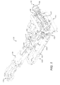
Figure 2 is an external perspective view of the bolter drill rig offigure 1 having a manipulator assembly configured to transport a drill rod between a drilling and a storage position according to a specific implementation of the present invention; -
Figure 3 is a further perspective view of the rig offigure 2 ; -
Figure 4 is a further perspective view of the rig offigure 3 ; -
Figure 5 is a perspective view of the manipulator assembly with parts removed for illustrative purposes; -
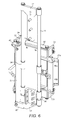
Figure 6 is a further perspective view of the manipulator assembly offigure 5 with parts removed for illustrate purposes; -
Figure 7 is a further perspective view of the manipulator assembly offigure 6 with parts removed for illustrate purposes; -
Figure 8 is a further perspective view of the manipulator assembly offigure 7 with parts removed for illustrate purposes; - The subject invention will be described with reference to a specific implementation mounted upon a bolter miner being an electrically powered, track-mounted continuous mining machine designed to excavate roadways and install roof bolts simultaneously. However, as will be appreciated, the present rig and manipulator arm may be mounted on a variety of mining machines that employ drill and/or bolting rigs including dedicated bolters, roadheaders, platform bolters and the like.
- Referring to
figure 1 , amining machine 100 comprises amain frame 101 that provides support for an undercarriage orchassis 109 that supports a pair of endless driventracks 113 for propelling themachine 100 over the ground and along a tunnel to advance forwardly through a material deposit seam.Main frame 101 comprises a generally forward end 102 and a generallyrearward end 103. Aconveyor 104 extends substantially from forward end 102 torearward end 103 and is adapted to carry material dislodged from the cutting face for subsequent discharge and stock piling at a remote location optionally using additional conveying and mining apparatus. Amovable cutting boom 105 is pivotally mounted at oneend 112 tomain frame 101 via a pivot mounting 110 and comprises asecond end 106 mounting a cuttinghead 115 that in turn mounts a plurality ofrotatable drums 107. Cuttingbits 108 project radially from eachdrum 107 and are specifically adapted to cut into and dislodge the mineral material to be mined from the seam.Boom 105 and inparticular end 106 is capable of being raised or lowered relative tomain frame 101 andendless tracks 113 to enablemachine 100 to cut the seam face over a varying height range above the ground of the mine tunnel.Boom 105 is operated by hydraulic rams and other associated components as will be appreciated by those skilled in the art.Machine 100 further comprises agathering head 117 mounted at forward end 102 ofmain frame 101.Head 117 is configured to collect material removed from the deposit seam by the cutting action ofhead 115. The cut material is then transported rearwardly from gatheringhead 117 viaconveyor 104. - A
canopy 111 comprises a vertically uppermost region having a generally planar configuration and is adapted for being raised vertically upward fromframe 101 in a manner similar to cuttinghead 115 so as to contact the mine roof to provide structural support as necessary during the cutting and roof bolting operations. Additionally, atail section 114 projects rearwardly from therearward end 103 offrame 101 to carryrearwardly conveyor 104 to adischarge end 116 representing a rearwardmost part of thecontinuous machine 100. Cuttinghead 115 is mounted at theforwardmost end 106 of cuttingboom 105 and is positionally supported by a pair of gear carriers 302 that extend fromboom 105 andcouple head 115 tomachine 100. A pair ofbolter drilling rigs 10 is mounted at the frame forwardmost end 102 immediately behind cutting and gathering heads 115, 117 and laterally to either side ofboom 105. Eachrig 10 is configured for operation in two modes including a first drilling mode in which a drill rod is driven into the mine roof or sidewall to create a borehole and a second mode in which a roof or rib bolt is driven by the same drive motor into the as-formed borehole. - Referring to
figures 2 to 8 , thebolter rig 10 comprises an elongate main frame to mount various moving components of the rig and various static components. The main frame comprises, in part, a pair of parallel elongate support struts 11 extending lengthwise along aframe gantry 29. A rotational drive motor indicated generally byreference 15 is mounted via acarriage shuttle 28 togantry 29. Achain drive 41 provides a movable link betweencarriage 28 andgantry 29 to enabledrive motor 15 to move linearly in a longitudinal direction x along themain frame 11, 29. - Each of the support struts 11 mounts internally a respective
linear actuator 12 capable of liner extension and retraction relative to struts 11. Ahead plate 13 is attached to respective endmost regions of each actuator 12 such that by actuation,head plate 13 is capable of lengthwise extension in direction x from struts 11 andgantry 29.Head plate 13 is configured specifically for positioning in contact with a mine roof or wall during drilling and bolting procedures.Plate 13 comprises anaperture 19 through which adrill rod 14 and a roof or rib bolt (not shown) are capable of passing during drilling and bolting operations.Aperture 19 is centred on a longitudinally axis ofdrive unit 15 corresponding to the axis ofrod 14 when installed and positioned at thedrive unit 15 for drilling parallel to x direction. In a typical drilling operation, driveunit 15 is configured to engagedrill rod 14 and then to advance linearly alongframe parts 11, 29 towardshead plate 13 that is maintained in an extended position fromframe 11, 29 in contact with the mine roof or wall. Once a borehole is created,rod 14 is retracted via a reverse linear movement of drive unit 15 (via chain drive 41) alongframe 11, 29. A roof or rib bolt (not shown) is then installed and centred atdrive unit 15 which is advanced a second time towardshead plate 13 to embed the bolt into the as-formed bore at the mine roof or wall. - The present
bolter mining rig 10 is configured specifically for the automated or semi-automated displacement of the drill rod relative to driveunit 15 to enable convenient and rapid interchange of the drill rod and the roof or rib bolt. In particular,rig 10 comprises a drill rod manipulator assembly represented generally byreference 16. The assembly comprises a pair of spaced apart and parallelelongate bars 18 mounted at respective first and second ends via respective attachment braces 17. Eachbrace 17 is rigidly mounted to one side ofmain frame gantry 29 in an orientation such that bars 18 are aligned parallel with struts 11.Braces 17 are mounted at one side of thedrill rig 10 whilst thedrive unit 15 andcarriage 28 are positioned at an adjacent second side of therig 10 to allow unhindered longitudinal travel of thedrive unit 15 in the x direction towards and fromhead plate 13.Bars 18 and braces 17 are substantially rigidly mounted atrig 10 so as to be stationary.Manipulator assembly 16 further comprises a shuttling component that is configured to shuttle linearly alongbars 18 in a parallel direction of travel relative to driveunit 15. In particular, the movable components comprises a manipulator arm having a base part represented generally byreference 26 and an extender part represented generally byreference 21.Base part 26 is movably mounted on eachbar 18 via a first pair and a second pair of spaced apartsleeves 36 capable of sliding linearly along eachbar 18.Base part 26 comprises aflange 43 that mounts one end of alinear actuator 27 mounted at an opposite end to aboss 30 rigidly mounted toactuator frame base 17. Accordingly,actuator 27 via linear extension and retraction is configured to drive sliding movement ofbase part 26 alongbars 18 in the x direction towards and away fromdrive unit 15 andhead plate 13. -
Base part 26 further comprises arear wall 34 and afront wall 35 extending in a lengthwise direction ofbase part 26. A pair ofguide rails 32 extends betweenwalls base part 26 in a direction perpendicular to bars 18. A bridge plate extends lengthwise betweenrails 32 and is mounted for sliding movement alongrails 32 via a pair of respective mountingsleeves 33 provided at each end ofbridge plate 31.Base part 26 further comprises a pair of widthwise extendingwalls 24, each comprising a curvedelongate slot 25 extending in a direction between the front andrear walls - The
extender part 21 of the manipulator arm is movably mounted atbase part 26 via alinear actuator 22.Extender part 21 is connected to bridgeplate 31 such that actuation ofbridge plate 31 for travel along therails 32 imparts a lateral extension ofextender part 21 frombase part 26 in a direction z perpendicular tobars 18 and the x direction of travel ofdrive unit 15.Extender part 21 extends laterally outward frombase part 26 via anaperture 42 formed in thefront wall 35 ofbase part 26. -
Extender part 21 further comprises amount wall 38 extending in the z direction parallel torails 32 and comprising anelongate slot 39 provided at one end. Apivot pin 40 mounts a pair of hingingscissor arms 37 capable of opening and closing aboutpivot 40. Each of thescissor arms 37 mount a respectivefirst jaw 20a and asecond jaw 20b configured to open and close relative to one another to release andgrip drill rod 14 via a claw like engaging action.Jaws linear actuator 23 mounted atextender part 21 that is mounted in turn atsupport mount wall 38. That is,actuator 23 provides displacement ofpivot pin 40 withinslot 39 that acts to pivotscissor arms 37 to open andclose jaws -
Extender part 21 is hingebly mounted atbase part 26 with the hinging facilitated via engagement of a pair of lugs (not shown) configured to travel within the elongatecurved slots 25. When actuated,bridge plate 31 is configured to move along rails 32 to forceextender part 21 laterally outward frombase part 26 in the z direction perpendicular tobars 18 orientated in the x direction. Via the pivot mounting ofextender part 21 atbase part 26, theextender part 21 is configured to pivot downwardly (or upwardly) relative to basepart 26 out of plane with thebase part 26 and bars 18. This pivoting action occurs when theextender part 21 is displaced laterally sideward and is moved to its fully extended position. In the fully extended position,jaws drive unit 15 corresponding to the longitudinal axis ofdrill rod 14 when engaged in position for drilling. -
Manipulator assembly 16 is advantageously mounted at a different and adjacent side ofdrill rig 10 relative to thedrive unit 15 andcarriage 28 to allow unhindered access to the region of the longitudinal axis centred ondrive unit 15 for interchange of thedrill rod 14 with a roof or rib bolt (not shown). Such a configuration necessitates amanipulator arm assembly 16 configured to 'reach' sideways (in the z direction and then to pivot and travel in the y direction) from the region of mounting of themanipulator 16 towards the axial centre ofdrive unit 15. Accordingly,extender part 21 is capable of moving laterally sideways to be brought into position at the appropriate side of therig 10 to either remove or deliver adrill rod 14 to the axially centred position atdrive unit 15. Additionally, in order to provide unhindered roof or rib bolting once the borehole has been created bydrill rod 14, the manipulator arm is configured to shuttle rearwardly away fromhead plate 13 in the x direction towardsdrive unit 15 so as to carryrod 14 to a storage position both at the side of mounting of themanipulator assembly 16 and also a linearly retracted position away fromhead plate 13. Accordingly, the present manipulator arm is configured to reliably transportdrill rod 14 between a drilling position centred atunit 15 and a storage position displaced laterally to one side ofdrive unit 15 and axially rearward fromhead plate 13. - According to the subject invention,
manipulator assembly 16 comprises a compact construction so as to minimise the occupied volume at the mounting side ofmain frame 11, 29. In particular, a distance in the y direction by themanipulator assembly 16 projects laterally from themain frame 11, 29 is less than a distance in the y direction by which driveunit 15 projects laterally from main frame11, 29 (including carriage 28). Additionally, the distance in the y direction by which themanipulator assembly 16 projects laterally frommain frame 11, 29 is approximately equal to or less than a thickness of themain frame 11, 29 in the y direction perpendicular to a length of the main frame in the x direction. Thepresent manipulator 16 may therefore be conveniently mounted at an existingbolter drill rig 10 andmobile mining machine 100 without modification so as to be positioned immediately behind heads 115, 117 andadjacent boom 105.
Claims (15)
- A bolting drill rig (10) mountable at a mining machine (100), the rig (10) comprising:an elongate main frame (11, 29);a drill drive unit (15) to provide rotational drive to a drill rod (14) used to create a bore hole in mine roof or wall to receive a bolt;a head (13) movably mounted at the frame (11, 29) being configured to brace against the roof or wall of the mine during drilling;characterised by:a drill rod manipulator assembly (16) mountable at the frame (11, 29) and having a manipulator arm (21, 26) mounted to move in a first lengthwise direction along the frame (11, 29) between a rod storage position away from the head (13) and a rod drilling position towards the head (13) relative to the lengthwise direction of the frame (11, 29);at least a part of the arm (21, 26) mounted to move in a second lateral direction substantially perpendicular or transverse to the first direction between a retracted state to provide the rod (14) in the storage position laterally to one side of the drive unit (15) and an extended state to provide the rod (14) in the drilling position centred with the drive unit (15); anda releasable rod engager (20a, 20b) provided at the arm (21, 26) to grip the rod (14) for coupled movement with the arm (21, 26).
- The rig as claimed in claim 1 further comprising a manipulator frame (17, 18) upon which the arm (21, 26) is mounted for movement in the first direction along the main frame (11, 29).
- The rig as claimed in claim 1 or 2 wherein a distance by the manipulator assembly (16) projects laterally from the main frame (11, 29) is equal to or less than a distance by which the drive unit (15) projects laterally from the main frame (11, 29).
- The rig as claimed in any preceding claim wherein the drive unit (15) is mounted at a first side of the main frame (11, 29) and the manipulator assembly (16) is mounted at a second side of the main frame (11, 29), wherein the arm (21, 26) is configured to move laterally in the second direction and to pivot between the retracted state and the extended state such that in the retracted state the arm (21, 26) does not obscure an axis centred on the drive unit (15) and in the extended state provides the drill rod (14) in the position centred with the drive unit (15).
- The rig as claimed in any preceding claim wherein the drive unit (15) is mounted at the main frame (11, 29) via a shuttle carriage (28) to enable the drive unit (15) to move lengthwise along the main frame (11, 29) relative to the head (13).
- The rig as claimed in claim 5 wherein the head (13) is mounted at the main frame (11, 29) via at least one linear actuator (12) and configured to be extended from or retracted at the main frame (11, 29) relative to the drive unit (15).
- The rig as claimed in any preceding claim when dependent on claim 2 wherein the manipulator arm (21, 26) comprises:a base part (26) mounted at and configured to slide along the manipulator frame (17, 18); andan extender part (21) capable of extending laterally from the base part (26) in the second direction substantially perpendicular or transverse to the length of the main frame (11,29).
- The rig as claimed in claim 7 further comprising at least one linear actuator (22) connecting the base part (26) and the extender part (21) to drive movement of the extender (21) part in the second direction.
- The rig as claimed in claim 7 or 8 further comprising at least one linear actuator (27) connected between the base part (26) and the manipulator frame (17, 18) to drive linear movement of the base part (26) in the first direction along the manipulator frame (17, 18).
- The rig as claimed in any preceding claim wherein the rod engager (20a, 20b) comprises a single jaw or a pair of opposed jaws to open and close to release and grip the drill rod (14) and at least one actuator (23) to drive a movement of the jaw or jaws to open and close about the drill rod (14).
- The rig as claimed in any one of claims 7 or 8 further comprising at least one pivot mounting connecting the base part (26) to the extender part (21) to enable the extender part to pivot relative to the base part.
- The rig as claimed in claim 11 wherein the extender part (21) is configured to pivot through 20 to 70° relative to the base part (26).
- The rig as claimed in any preceding claim when dependent on claim 2 wherein a length of the manipulator frame (17, 18) is at least half a length of the main frame (11, 29) such that the arm is capable of moving in the first direction over at least half of the length of the main frame (11, 29) to move the rod (14) in a direction away from the head (13).
- A rod manipulator (16) mountable at a mining machine near a drill drive unit (15) and configured for moving a rod (14) used for drilling or bolting operations, the manipulator (16) comprising:a manipulator frame (17,18) mountable at a frame (11,29) of the mining machine;a manipulator arm (21, 26) mounted to move in a first lengthwise direction along the manipulator frame (17, 18) between a rod storage position and a rod drilling position;at least a part of the arm (21, 26) mounted to move in a second lateral direction substantially perpendicular or transverse to the first direction between a retracted state to provide the rod (14) in the storage position laterally to one side of the drive unit (15) and an extended state to provide the rod (14) in the drilling position centred with the drive unit (15); anda releasable rod engager (20a, 20b) provided at the arm (21, 26) to grip the rod (14) for coupled movement with the arm (21, 26).
- A mobile mining machine (100) for roof or wall bolting comprising a rig (10) as claimed in any one of claims 1 to 13.
Priority Applications (9)
| Application Number | Priority Date | Filing Date | Title |
|---|---|---|---|
| PL14162337T PL2924236T3 (en) | 2014-03-28 | 2014-03-28 | Mining drill rig |
| ES14162337.1T ES2597778T3 (en) | 2014-03-28 | 2014-03-28 | Mining Drilling Equipment |
| EP14162337.1A EP2924236B1 (en) | 2014-03-28 | 2014-03-28 | Mining drill rig |
| AU2015238709A AU2015238709A1 (en) | 2014-03-28 | 2015-03-09 | Rod manipulator for a mining drill rig |
| RU2016142187A RU2016142187A (en) | 2014-03-28 | 2015-03-09 | Mining Drilling Rig |
| US15/129,766 US9903160B2 (en) | 2014-03-28 | 2015-03-09 | Rod manipulator for a mining drill rig |
| CN201580015264.7A CN106232938A (en) | 2014-03-28 | 2015-03-09 | Lever operation device for mining rig |
| PCT/EP2015/054797 WO2015144424A1 (en) | 2014-03-28 | 2015-03-09 | Rod manipulator for a mining drill rig |
| CA2940110A CA2940110A1 (en) | 2014-03-28 | 2015-03-09 | Rod manipulator for a mining drill rig |
Applications Claiming Priority (1)
| Application Number | Priority Date | Filing Date | Title |
|---|---|---|---|
| EP14162337.1A EP2924236B1 (en) | 2014-03-28 | 2014-03-28 | Mining drill rig |
Publications (2)
| Publication Number | Publication Date |
|---|---|
| EP2924236A1 true EP2924236A1 (en) | 2015-09-30 |
| EP2924236B1 EP2924236B1 (en) | 2016-07-13 |
Family
ID=50389922
Family Applications (1)
| Application Number | Title | Priority Date | Filing Date |
|---|---|---|---|
| EP14162337.1A Not-in-force EP2924236B1 (en) | 2014-03-28 | 2014-03-28 | Mining drill rig |
Country Status (9)
| Country | Link |
|---|---|
| US (1) | US9903160B2 (en) |
| EP (1) | EP2924236B1 (en) |
| CN (1) | CN106232938A (en) |
| AU (1) | AU2015238709A1 (en) |
| CA (1) | CA2940110A1 (en) |
| ES (1) | ES2597778T3 (en) |
| PL (1) | PL2924236T3 (en) |
| RU (1) | RU2016142187A (en) |
| WO (1) | WO2015144424A1 (en) |
Cited By (3)
| Publication number | Priority date | Publication date | Assignee | Title |
|---|---|---|---|---|
| CN113802981A (en) * | 2021-08-25 | 2021-12-17 | 江西鑫通机械制造有限公司 | Single track hangs hydraulic pressure stock drill carriage |
| US11274506B2 (en) | 2018-06-05 | 2022-03-15 | Joy Global Underground Mining Llc | Drilling and bolting device |
| CN118464526A (en) * | 2024-07-12 | 2024-08-09 | 新乡煜昊机电设备有限公司 | Concrete drilling coring equipment for quality supervision of constructional engineering |
Families Citing this family (12)
| Publication number | Priority date | Publication date | Assignee | Title |
|---|---|---|---|---|
| CN104718346B (en) | 2012-09-14 | 2019-02-22 | 久益环球地下采矿有限责任公司 | cutter head for excavator |
| US11391149B2 (en) | 2016-08-19 | 2022-07-19 | Joy Global Underground Mining Llc | Mining machine with articulating boom and independent material handling system |
| AU2017312142B2 (en) | 2016-08-19 | 2023-03-16 | Joy Global Underground Mining Llc | Cutting device and support for same |
| FI3516153T3 (en) | 2016-09-23 | 2024-02-16 | Joy Global Underground Mining Llc | Rock cutting device |
| PE20210356A1 (en) * | 2018-07-25 | 2021-02-26 | Joy Global Underground Mining Llc | ROCK CUTTING SET |
| EP3947892B1 (en) * | 2019-03-29 | 2024-08-21 | Boart Longyear Company | Underground drill rig and systems and methods of using same |
| CN112727346B (en) * | 2020-12-31 | 2023-01-03 | 中国煤炭科工集团太原研究院有限公司 | Lightweight rack and pinion climbing anchor protects rig |
| CN112963185B (en) * | 2021-03-15 | 2022-12-27 | 中国煤炭科工集团太原研究院有限公司 | Slide rail device and anchor rod drilling machine with same |
| CN113530586B (en) * | 2021-08-13 | 2024-01-30 | 中国煤炭科工集团太原研究院有限公司 | Mechanism for automatically drilling, pushing medicine, delivering anchor cable and tensioning and fixedly connecting and cutting off |
| CN113550770B (en) * | 2021-08-13 | 2024-04-05 | 中国煤炭科工集团太原研究院有限公司 | Automatic drilling, pushing, anchor cable feeding and tensioning, fixedly connecting and cutting mechanism for non-coal mine |
| CN113863855B (en) * | 2021-10-22 | 2024-05-07 | 山东兖煤黑豹矿业装备有限公司 | Gantry type mining hydraulic drill carriage |
| CN114922566B (en) * | 2022-07-20 | 2022-10-04 | 山东济矿鲁能煤电股份有限公司阳城煤矿 | Rock stratum drilling equipment for coal mining |
Citations (4)
| Publication number | Priority date | Publication date | Assignee | Title |
|---|---|---|---|---|
| EP0470061A2 (en) * | 1990-07-10 | 1992-02-05 | Atlas Copco Construction and Mining Technique AB | Device for setting a rock bolt |
| US20030066665A1 (en) * | 2001-04-20 | 2003-04-10 | Coombs Perry L. | Translating turret rock bolter |
| EP1533470A1 (en) * | 2003-11-18 | 2005-05-25 | Sandvik Tamrock Secoma S.A.S. | Drilling and bolting head for a bolting machine |
| DE102007038265B3 (en) * | 2007-08-13 | 2009-02-05 | Gta Maschinensysteme Gmbh | Apparatus for setting rock anchor, has drilling unit and anchor setting unit, which is adjustable arranged and formed between stand-by position and working position in each case |
Family Cites Families (6)
| Publication number | Priority date | Publication date | Assignee | Title |
|---|---|---|---|---|
| US2754087A (en) * | 1953-06-12 | 1956-07-10 | Travel Drill Company Inc | Mobile drilling equipment |
| SE388453B (en) * | 1973-05-08 | 1976-10-04 | Atlas Copco Ab | DEVICE FOR TRANSFER BARS FROM A MAGAZINE DOCTOR TO THE CENTER AXLE FOR A DRILL |
| AUPN571495A0 (en) * | 1995-09-28 | 1995-10-26 | Cram Australia Pty Ltd | Apparatus for the handling rods |
| US5791822A (en) * | 1996-09-27 | 1998-08-11 | Cram Australia Pty Ltd. | Rod handling apparatus and method |
| US6612803B1 (en) * | 2000-02-17 | 2003-09-02 | Strata Products (Usa), Inc. | Positioning cradle for mine roof supports |
| SE537968C2 (en) * | 2012-07-09 | 2015-12-22 | Atlas Copco Rock Drills Ab | Procedure and device for bolt installation in rock |
-
2014
- 2014-03-28 EP EP14162337.1A patent/EP2924236B1/en not_active Not-in-force
- 2014-03-28 ES ES14162337.1T patent/ES2597778T3/en active Active
- 2014-03-28 PL PL14162337T patent/PL2924236T3/en unknown
-
2015
- 2015-03-09 AU AU2015238709A patent/AU2015238709A1/en not_active Abandoned
- 2015-03-09 CA CA2940110A patent/CA2940110A1/en not_active Abandoned
- 2015-03-09 WO PCT/EP2015/054797 patent/WO2015144424A1/en not_active Ceased
- 2015-03-09 RU RU2016142187A patent/RU2016142187A/en not_active Application Discontinuation
- 2015-03-09 CN CN201580015264.7A patent/CN106232938A/en active Pending
- 2015-03-09 US US15/129,766 patent/US9903160B2/en not_active Expired - Fee Related
Patent Citations (4)
| Publication number | Priority date | Publication date | Assignee | Title |
|---|---|---|---|---|
| EP0470061A2 (en) * | 1990-07-10 | 1992-02-05 | Atlas Copco Construction and Mining Technique AB | Device for setting a rock bolt |
| US20030066665A1 (en) * | 2001-04-20 | 2003-04-10 | Coombs Perry L. | Translating turret rock bolter |
| EP1533470A1 (en) * | 2003-11-18 | 2005-05-25 | Sandvik Tamrock Secoma S.A.S. | Drilling and bolting head for a bolting machine |
| DE102007038265B3 (en) * | 2007-08-13 | 2009-02-05 | Gta Maschinensysteme Gmbh | Apparatus for setting rock anchor, has drilling unit and anchor setting unit, which is adjustable arranged and formed between stand-by position and working position in each case |
Cited By (3)
| Publication number | Priority date | Publication date | Assignee | Title |
|---|---|---|---|---|
| US11274506B2 (en) | 2018-06-05 | 2022-03-15 | Joy Global Underground Mining Llc | Drilling and bolting device |
| CN113802981A (en) * | 2021-08-25 | 2021-12-17 | 江西鑫通机械制造有限公司 | Single track hangs hydraulic pressure stock drill carriage |
| CN118464526A (en) * | 2024-07-12 | 2024-08-09 | 新乡煜昊机电设备有限公司 | Concrete drilling coring equipment for quality supervision of constructional engineering |
Also Published As
| Publication number | Publication date |
|---|---|
| ES2597778T3 (en) | 2017-01-23 |
| AU2015238709A1 (en) | 2016-09-01 |
| RU2016142187A (en) | 2018-04-28 |
| PL2924236T3 (en) | 2017-01-31 |
| EP2924236B1 (en) | 2016-07-13 |
| CA2940110A1 (en) | 2015-10-01 |
| CN106232938A (en) | 2016-12-14 |
| RU2016142187A3 (en) | 2018-09-03 |
| US20170204666A1 (en) | 2017-07-20 |
| WO2015144424A1 (en) | 2015-10-01 |
| US9903160B2 (en) | 2018-02-27 |
Similar Documents
| Publication | Publication Date | Title |
|---|---|---|
| EP2924236B1 (en) | Mining drill rig | |
| EP2821591B1 (en) | Mining machine roof bolting rig | |
| US10364675B2 (en) | Cutting apparatus | |
| CN105569701B (en) | Suspension device is tunneled suitable for the step type that hard-rock tunnel is tunneled | |
| CN205578020U (en) | Formula of taking a step tunnelling supporting device suitable for hard rock tunnelling | |
| EP3420190B1 (en) | Mesh handling device for mining or tunnelling equipment | |
| US4149604A (en) | Mining equipment | |
| AU2004216593B2 (en) | Combination panline and utility drilling or bolting unit | |
| US6416134B1 (en) | Underground auger system | |
| BR112020019689A2 (en) | MATERIAL HANDLING APPLIANCE FOR A MINING MACHINE | |
| RU2773833C2 (en) | Screen for cutting frame of mining machine | |
| WO2012126036A1 (en) | A shearer mounted drill rig | |
| CA2615801A1 (en) | Narrow bench mining system |
Legal Events
| Date | Code | Title | Description |
|---|---|---|---|
| PUAI | Public reference made under article 153(3) epc to a published international application that has entered the european phase |
Free format text: ORIGINAL CODE: 0009012 |
|
| 17P | Request for examination filed |
Effective date: 20140328 |
|
| AK | Designated contracting states |
Kind code of ref document: A1 Designated state(s): AL AT BE BG CH CY CZ DE DK EE ES FI FR GB GR HR HU IE IS IT LI LT LU LV MC MK MT NL NO PL PT RO RS SE SI SK SM TR |
|
| AX | Request for extension of the european patent |
Extension state: BA ME |
|
| GRAP | Despatch of communication of intention to grant a patent |
Free format text: ORIGINAL CODE: EPIDOSNIGR1 |
|
| INTG | Intention to grant announced |
Effective date: 20160414 |
|
| RBV | Designated contracting states (corrected) |
Designated state(s): AL AT BE BG CH CY CZ DE DK EE ES FI FR GB GR HR HU IE IS IT LI LT LU LV MC MK MT NL NO PL PT RO RS SE SI SK SM TR |
|
| GRAS | Grant fee paid |
Free format text: ORIGINAL CODE: EPIDOSNIGR3 |
|
| GRAA | (expected) grant |
Free format text: ORIGINAL CODE: 0009210 |
|
| AK | Designated contracting states |
Kind code of ref document: B1 Designated state(s): AL AT BE BG CH CY CZ DE DK EE ES FI FR GB GR HR HU IE IS IT LI LT LU LV MC MK MT NL NO PL PT RO RS SE SI SK SM TR |
|
| REG | Reference to a national code |
Ref country code: GB Ref legal event code: FG4D |
|
| REG | Reference to a national code |
Ref country code: AT Ref legal event code: REF Ref document number: 812508 Country of ref document: AT Kind code of ref document: T Effective date: 20160715 Ref country code: CH Ref legal event code: EP |
|
| REG | Reference to a national code |
Ref country code: IE Ref legal event code: FG4D |
|
| REG | Reference to a national code |
Ref country code: DE Ref legal event code: R096 Ref document number: 602014002612 Country of ref document: DE |
|
| REG | Reference to a national code |
Ref country code: LT Ref legal event code: MG4D |
|
| REG | Reference to a national code |
Ref country code: NL Ref legal event code: MP Effective date: 20160713 |
|
| REG | Reference to a national code |
Ref country code: AT Ref legal event code: MK05 Ref document number: 812508 Country of ref document: AT Kind code of ref document: T Effective date: 20160713 |
|
| REG | Reference to a national code |
Ref country code: ES Ref legal event code: FG2A Ref document number: 2597778 Country of ref document: ES Kind code of ref document: T3 Effective date: 20170123 |
|
| PG25 | Lapsed in a contracting state [announced via postgrant information from national office to epo] |
Ref country code: HR Free format text: LAPSE BECAUSE OF FAILURE TO SUBMIT A TRANSLATION OF THE DESCRIPTION OR TO PAY THE FEE WITHIN THE PRESCRIBED TIME-LIMIT Effective date: 20160713 Ref country code: FI Free format text: LAPSE BECAUSE OF FAILURE TO SUBMIT A TRANSLATION OF THE DESCRIPTION OR TO PAY THE FEE WITHIN THE PRESCRIBED TIME-LIMIT Effective date: 20160713 Ref country code: NO Free format text: LAPSE BECAUSE OF FAILURE TO SUBMIT A TRANSLATION OF THE DESCRIPTION OR TO PAY THE FEE WITHIN THE PRESCRIBED TIME-LIMIT Effective date: 20161013 Ref country code: IS Free format text: LAPSE BECAUSE OF FAILURE TO SUBMIT A TRANSLATION OF THE DESCRIPTION OR TO PAY THE FEE WITHIN THE PRESCRIBED TIME-LIMIT Effective date: 20161113 Ref country code: IT Free format text: LAPSE BECAUSE OF FAILURE TO SUBMIT A TRANSLATION OF THE DESCRIPTION OR TO PAY THE FEE WITHIN THE PRESCRIBED TIME-LIMIT Effective date: 20160713 Ref country code: LT Free format text: LAPSE BECAUSE OF FAILURE TO SUBMIT A TRANSLATION OF THE DESCRIPTION OR TO PAY THE FEE WITHIN THE PRESCRIBED TIME-LIMIT Effective date: 20160713 Ref country code: NL Free format text: LAPSE BECAUSE OF FAILURE TO SUBMIT A TRANSLATION OF THE DESCRIPTION OR TO PAY THE FEE WITHIN THE PRESCRIBED TIME-LIMIT Effective date: 20160713 Ref country code: RS Free format text: LAPSE BECAUSE OF FAILURE TO SUBMIT A TRANSLATION OF THE DESCRIPTION OR TO PAY THE FEE WITHIN THE PRESCRIBED TIME-LIMIT Effective date: 20160713 |
|
| PG25 | Lapsed in a contracting state [announced via postgrant information from national office to epo] |
Ref country code: LV Free format text: LAPSE BECAUSE OF FAILURE TO SUBMIT A TRANSLATION OF THE DESCRIPTION OR TO PAY THE FEE WITHIN THE PRESCRIBED TIME-LIMIT Effective date: 20160713 Ref country code: PT Free format text: LAPSE BECAUSE OF FAILURE TO SUBMIT A TRANSLATION OF THE DESCRIPTION OR TO PAY THE FEE WITHIN THE PRESCRIBED TIME-LIMIT Effective date: 20161114 Ref country code: SE Free format text: LAPSE BECAUSE OF FAILURE TO SUBMIT A TRANSLATION OF THE DESCRIPTION OR TO PAY THE FEE WITHIN THE PRESCRIBED TIME-LIMIT Effective date: 20160713 Ref country code: BE Free format text: LAPSE BECAUSE OF FAILURE TO SUBMIT A TRANSLATION OF THE DESCRIPTION OR TO PAY THE FEE WITHIN THE PRESCRIBED TIME-LIMIT Effective date: 20160713 Ref country code: AT Free format text: LAPSE BECAUSE OF FAILURE TO SUBMIT A TRANSLATION OF THE DESCRIPTION OR TO PAY THE FEE WITHIN THE PRESCRIBED TIME-LIMIT Effective date: 20160713 Ref country code: GR Free format text: LAPSE BECAUSE OF FAILURE TO SUBMIT A TRANSLATION OF THE DESCRIPTION OR TO PAY THE FEE WITHIN THE PRESCRIBED TIME-LIMIT Effective date: 20161014 |
|
| REG | Reference to a national code |
Ref country code: DE Ref legal event code: R097 Ref document number: 602014002612 Country of ref document: DE |
|
| PG25 | Lapsed in a contracting state [announced via postgrant information from national office to epo] |
Ref country code: RO Free format text: LAPSE BECAUSE OF FAILURE TO SUBMIT A TRANSLATION OF THE DESCRIPTION OR TO PAY THE FEE WITHIN THE PRESCRIBED TIME-LIMIT Effective date: 20160713 Ref country code: EE Free format text: LAPSE BECAUSE OF FAILURE TO SUBMIT A TRANSLATION OF THE DESCRIPTION OR TO PAY THE FEE WITHIN THE PRESCRIBED TIME-LIMIT Effective date: 20160713 |
|
| PLBE | No opposition filed within time limit |
Free format text: ORIGINAL CODE: 0009261 |
|
| STAA | Information on the status of an ep patent application or granted ep patent |
Free format text: STATUS: NO OPPOSITION FILED WITHIN TIME LIMIT |
|
| PG25 | Lapsed in a contracting state [announced via postgrant information from national office to epo] |
Ref country code: SK Free format text: LAPSE BECAUSE OF FAILURE TO SUBMIT A TRANSLATION OF THE DESCRIPTION OR TO PAY THE FEE WITHIN THE PRESCRIBED TIME-LIMIT Effective date: 20160713 Ref country code: BG Free format text: LAPSE BECAUSE OF FAILURE TO SUBMIT A TRANSLATION OF THE DESCRIPTION OR TO PAY THE FEE WITHIN THE PRESCRIBED TIME-LIMIT Effective date: 20161013 Ref country code: DK Free format text: LAPSE BECAUSE OF FAILURE TO SUBMIT A TRANSLATION OF THE DESCRIPTION OR TO PAY THE FEE WITHIN THE PRESCRIBED TIME-LIMIT Effective date: 20160713 Ref country code: SM Free format text: LAPSE BECAUSE OF FAILURE TO SUBMIT A TRANSLATION OF THE DESCRIPTION OR TO PAY THE FEE WITHIN THE PRESCRIBED TIME-LIMIT Effective date: 20160713 |
|
| 26N | No opposition filed |
Effective date: 20170418 |
|
| PGFP | Annual fee paid to national office [announced via postgrant information from national office to epo] |
Ref country code: ES Payment date: 20170214 Year of fee payment: 4 |
|
| PG25 | Lapsed in a contracting state [announced via postgrant information from national office to epo] |
Ref country code: SI Free format text: LAPSE BECAUSE OF FAILURE TO SUBMIT A TRANSLATION OF THE DESCRIPTION OR TO PAY THE FEE WITHIN THE PRESCRIBED TIME-LIMIT Effective date: 20160713 |
|
| PG25 | Lapsed in a contracting state [announced via postgrant information from national office to epo] |
Ref country code: CZ Free format text: LAPSE BECAUSE OF NON-PAYMENT OF DUE FEES Effective date: 20170328 |
|
| REG | Reference to a national code |
Ref country code: CH Ref legal event code: PL |
|
| PG25 | Lapsed in a contracting state [announced via postgrant information from national office to epo] |
Ref country code: MC Free format text: LAPSE BECAUSE OF FAILURE TO SUBMIT A TRANSLATION OF THE DESCRIPTION OR TO PAY THE FEE WITHIN THE PRESCRIBED TIME-LIMIT Effective date: 20160713 |
|
| REG | Reference to a national code |
Ref country code: IE Ref legal event code: MM4A |
|
| REG | Reference to a national code |
Ref country code: FR Ref legal event code: ST Effective date: 20171130 |
|
| PG25 | Lapsed in a contracting state [announced via postgrant information from national office to epo] |
Ref country code: FR Free format text: LAPSE BECAUSE OF NON-PAYMENT OF DUE FEES Effective date: 20170331 Ref country code: LU Free format text: LAPSE BECAUSE OF NON-PAYMENT OF DUE FEES Effective date: 20170328 |
|
| PG25 | Lapsed in a contracting state [announced via postgrant information from national office to epo] |
Ref country code: CH Free format text: LAPSE BECAUSE OF NON-PAYMENT OF DUE FEES Effective date: 20170331 Ref country code: IE Free format text: LAPSE BECAUSE OF NON-PAYMENT OF DUE FEES Effective date: 20170328 Ref country code: LI Free format text: LAPSE BECAUSE OF NON-PAYMENT OF DUE FEES Effective date: 20170331 |
|
| PGFP | Annual fee paid to national office [announced via postgrant information from national office to epo] |
Ref country code: DE Payment date: 20180313 Year of fee payment: 5 |
|
| PGFP | Annual fee paid to national office [announced via postgrant information from national office to epo] |
Ref country code: PL Payment date: 20180212 Year of fee payment: 5 |
|
| PG25 | Lapsed in a contracting state [announced via postgrant information from national office to epo] |
Ref country code: MT Free format text: LAPSE BECAUSE OF NON-PAYMENT OF DUE FEES Effective date: 20170328 |
|
| PG25 | Lapsed in a contracting state [announced via postgrant information from national office to epo] |
Ref country code: AL Free format text: LAPSE BECAUSE OF FAILURE TO SUBMIT A TRANSLATION OF THE DESCRIPTION OR TO PAY THE FEE WITHIN THE PRESCRIBED TIME-LIMIT Effective date: 20160713 |
|
| GBPC | Gb: european patent ceased through non-payment of renewal fee |
Effective date: 20180328 |
|
| PG25 | Lapsed in a contracting state [announced via postgrant information from national office to epo] |
Ref country code: GB Free format text: LAPSE BECAUSE OF NON-PAYMENT OF DUE FEES Effective date: 20180328 |
|
| PG25 | Lapsed in a contracting state [announced via postgrant information from national office to epo] |
Ref country code: HU Free format text: LAPSE BECAUSE OF FAILURE TO SUBMIT A TRANSLATION OF THE DESCRIPTION OR TO PAY THE FEE WITHIN THE PRESCRIBED TIME-LIMIT; INVALID AB INITIO Effective date: 20140328 |
|
| REG | Reference to a national code |
Ref country code: ES Ref legal event code: FD2A Effective date: 20190830 |
|
| REG | Reference to a national code |
Ref country code: DE Ref legal event code: R119 Ref document number: 602014002612 Country of ref document: DE |
|
| PG25 | Lapsed in a contracting state [announced via postgrant information from national office to epo] |
Ref country code: CY Free format text: LAPSE BECAUSE OF FAILURE TO SUBMIT A TRANSLATION OF THE DESCRIPTION OR TO PAY THE FEE WITHIN THE PRESCRIBED TIME-LIMIT Effective date: 20160713 Ref country code: ES Free format text: LAPSE BECAUSE OF NON-PAYMENT OF DUE FEES Effective date: 20180329 |
|
| PG25 | Lapsed in a contracting state [announced via postgrant information from national office to epo] |
Ref country code: MK Free format text: LAPSE BECAUSE OF FAILURE TO SUBMIT A TRANSLATION OF THE DESCRIPTION OR TO PAY THE FEE WITHIN THE PRESCRIBED TIME-LIMIT Effective date: 20160713 |
|
| PG25 | Lapsed in a contracting state [announced via postgrant information from national office to epo] |
Ref country code: DE Free format text: LAPSE BECAUSE OF NON-PAYMENT OF DUE FEES Effective date: 20191001 |
|
| PG25 | Lapsed in a contracting state [announced via postgrant information from national office to epo] |
Ref country code: TR Free format text: LAPSE BECAUSE OF FAILURE TO SUBMIT A TRANSLATION OF THE DESCRIPTION OR TO PAY THE FEE WITHIN THE PRESCRIBED TIME-LIMIT Effective date: 20160713 |
|
| PG25 | Lapsed in a contracting state [announced via postgrant information from national office to epo] |
Ref country code: PL Free format text: LAPSE BECAUSE OF NON-PAYMENT OF DUE FEES Effective date: 20190328 |