EP2923827A1 - Method for manufacturing motorcycle tire - Google Patents
Method for manufacturing motorcycle tire Download PDFInfo
- Publication number
- EP2923827A1 EP2923827A1 EP15160015.2A EP15160015A EP2923827A1 EP 2923827 A1 EP2923827 A1 EP 2923827A1 EP 15160015 A EP15160015 A EP 15160015A EP 2923827 A1 EP2923827 A1 EP 2923827A1
- Authority
- EP
- European Patent Office
- Prior art keywords
- belt
- raw tire
- ply
- tire body
- cylindrical
- Prior art date
- Legal status (The legal status is an assumption and is not a legal conclusion. Google has not performed a legal analysis and makes no representation as to the accuracy of the status listed.)
- Granted
Links
Images



Classifications
-
- B—PERFORMING OPERATIONS; TRANSPORTING
- B29—WORKING OF PLASTICS; WORKING OF SUBSTANCES IN A PLASTIC STATE IN GENERAL
- B29D—PRODUCING PARTICULAR ARTICLES FROM PLASTICS OR FROM SUBSTANCES IN A PLASTIC STATE
- B29D30/00—Producing pneumatic or solid tyres or parts thereof
- B29D30/06—Pneumatic tyres or parts thereof (e.g. produced by casting, moulding, compression moulding, injection moulding, centrifugal casting)
- B29D30/08—Building tyres
-
- B—PERFORMING OPERATIONS; TRANSPORTING
- B29—WORKING OF PLASTICS; WORKING OF SUBSTANCES IN A PLASTIC STATE IN GENERAL
- B29D—PRODUCING PARTICULAR ARTICLES FROM PLASTICS OR FROM SUBSTANCES IN A PLASTIC STATE
- B29D30/00—Producing pneumatic or solid tyres or parts thereof
- B29D30/06—Pneumatic tyres or parts thereof (e.g. produced by casting, moulding, compression moulding, injection moulding, centrifugal casting)
- B29D30/08—Building tyres
- B29D30/10—Building tyres on round cores, i.e. the shape of the core is approximately identical with the shape of the completed tyre
- B29D30/16—Applying the layers; Guiding or stretching the layers during application
- B29D30/1628—Applying the layers; Guiding or stretching the layers during application by feeding a continuous band and winding it helically, i.e. the band is fed while being advanced along the core axis, to form an annular element
-
- B—PERFORMING OPERATIONS; TRANSPORTING
- B29—WORKING OF PLASTICS; WORKING OF SUBSTANCES IN A PLASTIC STATE IN GENERAL
- B29D—PRODUCING PARTICULAR ARTICLES FROM PLASTICS OR FROM SUBSTANCES IN A PLASTIC STATE
- B29D30/00—Producing pneumatic or solid tyres or parts thereof
- B29D30/06—Pneumatic tyres or parts thereof (e.g. produced by casting, moulding, compression moulding, injection moulding, centrifugal casting)
- B29D30/08—Building tyres
- B29D30/20—Building tyres by the flat-tyre method, i.e. building on cylindrical drums
- B29D30/24—Drums
- B29D30/242—Drums for manufacturing substantially cylindrical tyre components without cores or beads, e.g. treads or belts
-
- B—PERFORMING OPERATIONS; TRANSPORTING
- B29—WORKING OF PLASTICS; WORKING OF SUBSTANCES IN A PLASTIC STATE IN GENERAL
- B29D—PRODUCING PARTICULAR ARTICLES FROM PLASTICS OR FROM SUBSTANCES IN A PLASTIC STATE
- B29D30/00—Producing pneumatic or solid tyres or parts thereof
- B29D30/06—Pneumatic tyres or parts thereof (e.g. produced by casting, moulding, compression moulding, injection moulding, centrifugal casting)
- B29D30/36—Expansion of tyres in a flat form, i.e. expansion to a toroidal shape independently of their building-up process, e.g. of tyres built by the flat-tyres method or by jointly covering two bead-rings
-
- B—PERFORMING OPERATIONS; TRANSPORTING
- B29—WORKING OF PLASTICS; WORKING OF SUBSTANCES IN A PLASTIC STATE IN GENERAL
- B29D—PRODUCING PARTICULAR ARTICLES FROM PLASTICS OR FROM SUBSTANCES IN A PLASTIC STATE
- B29D30/00—Producing pneumatic or solid tyres or parts thereof
- B29D30/06—Pneumatic tyres or parts thereof (e.g. produced by casting, moulding, compression moulding, injection moulding, centrifugal casting)
- B29D30/70—Annular breakers
-
- B—PERFORMING OPERATIONS; TRANSPORTING
- B32—LAYERED PRODUCTS
- B32B—LAYERED PRODUCTS, i.e. PRODUCTS BUILT-UP OF STRATA OF FLAT OR NON-FLAT, e.g. CELLULAR OR HONEYCOMB, FORM
- B32B1/00—Layered products having a non-planar shape
- B32B1/08—Tubular products
-
- B—PERFORMING OPERATIONS; TRANSPORTING
- B32—LAYERED PRODUCTS
- B32B—LAYERED PRODUCTS, i.e. PRODUCTS BUILT-UP OF STRATA OF FLAT OR NON-FLAT, e.g. CELLULAR OR HONEYCOMB, FORM
- B32B25/00—Layered products comprising a layer of natural or synthetic rubber
- B32B25/02—Layered products comprising a layer of natural or synthetic rubber with fibres or particles being present as additives in the layer
-
- B—PERFORMING OPERATIONS; TRANSPORTING
- B32—LAYERED PRODUCTS
- B32B—LAYERED PRODUCTS, i.e. PRODUCTS BUILT-UP OF STRATA OF FLAT OR NON-FLAT, e.g. CELLULAR OR HONEYCOMB, FORM
- B32B25/00—Layered products comprising a layer of natural or synthetic rubber
- B32B25/04—Layered products comprising a layer of natural or synthetic rubber comprising rubber as the main or only constituent of a layer, which is next to another layer of the same or of a different material
-
- B—PERFORMING OPERATIONS; TRANSPORTING
- B32—LAYERED PRODUCTS
- B32B—LAYERED PRODUCTS, i.e. PRODUCTS BUILT-UP OF STRATA OF FLAT OR NON-FLAT, e.g. CELLULAR OR HONEYCOMB, FORM
- B32B37/00—Methods or apparatus for laminating, e.g. by curing or by ultrasonic bonding
- B32B37/0046—Methods or apparatus for laminating, e.g. by curing or by ultrasonic bonding characterised by constructional aspects of the apparatus
-
- B—PERFORMING OPERATIONS; TRANSPORTING
- B32—LAYERED PRODUCTS
- B32B—LAYERED PRODUCTS, i.e. PRODUCTS BUILT-UP OF STRATA OF FLAT OR NON-FLAT, e.g. CELLULAR OR HONEYCOMB, FORM
- B32B37/00—Methods or apparatus for laminating, e.g. by curing or by ultrasonic bonding
- B32B37/02—Methods or apparatus for laminating, e.g. by curing or by ultrasonic bonding characterised by a sequence of laminating steps, e.g. by adding new layers at consecutive laminating stations
-
- B—PERFORMING OPERATIONS; TRANSPORTING
- B32—LAYERED PRODUCTS
- B32B—LAYERED PRODUCTS, i.e. PRODUCTS BUILT-UP OF STRATA OF FLAT OR NON-FLAT, e.g. CELLULAR OR HONEYCOMB, FORM
- B32B38/00—Ancillary operations in connection with laminating processes
- B32B38/0012—Mechanical treatment, e.g. roughening, deforming, stretching
-
- B—PERFORMING OPERATIONS; TRANSPORTING
- B29—WORKING OF PLASTICS; WORKING OF SUBSTANCES IN A PLASTIC STATE IN GENERAL
- B29D—PRODUCING PARTICULAR ARTICLES FROM PLASTICS OR FROM SUBSTANCES IN A PLASTIC STATE
- B29D30/00—Producing pneumatic or solid tyres or parts thereof
- B29D30/06—Pneumatic tyres or parts thereof (e.g. produced by casting, moulding, compression moulding, injection moulding, centrifugal casting)
- B29D30/08—Building tyres
- B29D2030/082—Optimizing the deposition of the layers on the tyre building support, e.g. by using mathematical methods
-
- B—PERFORMING OPERATIONS; TRANSPORTING
- B29—WORKING OF PLASTICS; WORKING OF SUBSTANCES IN A PLASTIC STATE IN GENERAL
- B29K—INDEXING SCHEME ASSOCIATED WITH SUBCLASSES B29B, B29C OR B29D, RELATING TO MOULDING MATERIALS OR TO MATERIALS FOR MOULDS, REINFORCEMENTS, FILLERS OR PREFORMED PARTS, e.g. INSERTS
- B29K2277/00—Use of PA, i.e. polyamides, e.g. polyesteramides or derivatives thereof, as reinforcement
- B29K2277/10—Aromatic polyamides [Polyaramides] or derivatives thereof
-
- B—PERFORMING OPERATIONS; TRANSPORTING
- B29—WORKING OF PLASTICS; WORKING OF SUBSTANCES IN A PLASTIC STATE IN GENERAL
- B29K—INDEXING SCHEME ASSOCIATED WITH SUBCLASSES B29B, B29C OR B29D, RELATING TO MOULDING MATERIALS OR TO MATERIALS FOR MOULDS, REINFORCEMENTS, FILLERS OR PREFORMED PARTS, e.g. INSERTS
- B29K2305/00—Use of metals, their alloys or their compounds, as reinforcement
- B29K2305/08—Transition metals
- B29K2305/12—Iron
-
- B—PERFORMING OPERATIONS; TRANSPORTING
- B32—LAYERED PRODUCTS
- B32B—LAYERED PRODUCTS, i.e. PRODUCTS BUILT-UP OF STRATA OF FLAT OR NON-FLAT, e.g. CELLULAR OR HONEYCOMB, FORM
- B32B38/00—Ancillary operations in connection with laminating processes
- B32B38/0012—Mechanical treatment, e.g. roughening, deforming, stretching
- B32B2038/0028—Stretching, elongating
-
- B—PERFORMING OPERATIONS; TRANSPORTING
- B32—LAYERED PRODUCTS
- B32B—LAYERED PRODUCTS, i.e. PRODUCTS BUILT-UP OF STRATA OF FLAT OR NON-FLAT, e.g. CELLULAR OR HONEYCOMB, FORM
- B32B2262/00—Composition or structural features of fibres which form a fibrous or filamentary layer or are present as additives
- B32B2262/02—Synthetic macromolecular fibres
- B32B2262/0261—Polyamide fibres
- B32B2262/0269—Aromatic polyamide fibres
-
- B—PERFORMING OPERATIONS; TRANSPORTING
- B32—LAYERED PRODUCTS
- B32B—LAYERED PRODUCTS, i.e. PRODUCTS BUILT-UP OF STRATA OF FLAT OR NON-FLAT, e.g. CELLULAR OR HONEYCOMB, FORM
- B32B2262/00—Composition or structural features of fibres which form a fibrous or filamentary layer or are present as additives
- B32B2262/10—Inorganic fibres
- B32B2262/103—Metal fibres
-
- B—PERFORMING OPERATIONS; TRANSPORTING
- B32—LAYERED PRODUCTS
- B32B—LAYERED PRODUCTS, i.e. PRODUCTS BUILT-UP OF STRATA OF FLAT OR NON-FLAT, e.g. CELLULAR OR HONEYCOMB, FORM
- B32B2305/00—Condition, form or state of the layers or laminate
- B32B2305/08—Reinforcements
-
- B—PERFORMING OPERATIONS; TRANSPORTING
- B32—LAYERED PRODUCTS
- B32B—LAYERED PRODUCTS, i.e. PRODUCTS BUILT-UP OF STRATA OF FLAT OR NON-FLAT, e.g. CELLULAR OR HONEYCOMB, FORM
- B32B2309/00—Parameters for the laminating or treatment process; Apparatus details
- B32B2309/08—Dimensions, e.g. volume
-
- B—PERFORMING OPERATIONS; TRANSPORTING
- B32—LAYERED PRODUCTS
- B32B—LAYERED PRODUCTS, i.e. PRODUCTS BUILT-UP OF STRATA OF FLAT OR NON-FLAT, e.g. CELLULAR OR HONEYCOMB, FORM
- B32B2597/00—Tubular articles, e.g. hoses, pipes
Definitions
- the present invention relates to a method for manufacturing a motorcycle tire with enhanced uniformity obtained by keeping belt cords from meandering.
- the tread section of a motorcycle tire is formed to have a low, arc-shaped profile with a small curvature.
- uniformity may be lowered if the belt cords of a belt ply meander and become disarrayed. Accordingly, various manufacturing methods have been proposed for keeping belt cords from meandering.
- patent publication 1 discloses a manufacturing method as follows: When a cylindrical belt ply is bonded to a raw tire body expanded in a toroidal shape, the cylindrical belt ply and the raw tire body are expanded in a radially outward direction by applying inflation pressure to the raw tire body while reducing the distance between bead cores so that the belt ply abuts the raw tire body from the tire equator all the way to both of the tire outer edges.
- patent publication 2 discloses a manufacturing method as follows: an arc-shaped profile deck divided into multiple segments in a peripheral direction protrudes from the inner circumferential surface of a cylindrical belt ply in the radially outward direction so as to shape a belt ply in a curved profile.
- the resultant raw tire may have a profile different from that of a vulcanizing die.
- the rubber or belt cords in the vulcanizing die may move significantly, causing the belt cords to meander. Accordingly, uniformity may be lowered.
- the profile of a belt ply is curved according to the vulcanizing die.
- the binding force of the belt ply increases when steel cords or aramid fibers are used for belt cords.
- the present invention was carried out in consideration of the above-mentioned problems. Its objective is to provide a method for manufacturing a motorcycle tire capable of keeping belt cords from meandering so as to enhance uniformity.
- One aspect of the present invention is a method for manufacturing a motorcycle tire.
- the motorcycle tire has a carcass extending from the tread section through a sidewall to reach the bead core of a bead section, and a belt layer positioned on the radially outer side of the carcass and on the inner side of the tread section.
- the belt layer is formed with a belt ply made of multiple belt cords.
- Such a manufacturing method is characterized by including a raw-tire-body forming process to form a cylindrical raw tire body that contains a cylindrical carcass body in which a sheet-type carcass ply of the carcass is wound to be cylindrical, and bead cores are provided on both edges of the carcass ply; and a belt-ply forming process to form a cylindrical belt ply that is wound in a cylindrical shape.
- the belt-ply-forming process includes the following steps: a bell-ring closing step to move a pair of cylindrical bell rings, which are supported to be movable for a short distance toward both sides of the tire in axial directions with the tire equatorial plane set as the center of movement and are positioned on the outside of the raw tire body to be concentric with the tire, from a standby position on the axially outer side toward the axially inner side of the tire leaving a gap in between; a first expansion step to expand the raw tire body in a toroidal shape by filling the raw tire body at a first inflation pressure, while reducing the distance between the bead cores to a first distance so that the apex of the raw tire body protrudes toward the radially outer side through the gap left between the paired bell rings; a winding step to wind a sheet-type belt ply by extending it on the pair of bell rings so as to form a cylindrical belt ply with its inner circumferential surface bonded to the apex of the
- the second inflation pressure is preferred to be 150 ⁇ 300 kPa.
- the time for increasing from the first inflation pressure to the second inflation pressure is preferred to be 10 ⁇ 30 seconds.
- the internal diameter (Dc) on the equator of the cylindrical belt ply after the belt bonding step is conducted is preferred to be greater than the external diameter (Db) of the bell rings, and the internal diameter (Ds) at an axially peripheral edge of the cylindrical belt ply after the belt bonding step is conducted is preferred to be smaller than the external diameter (Db) of the bell rings.
- the internal diameter (Dc) on the equator of the cylindrical belt ply, the external diameter (Db) of the bell rings, and the internal diameter (Ds) at an axially peripheral edge of the cylindrical belt ply are preferred to satisfy the following relationship. 0.15 ⁇ Db - Ds / Dc - Ds ⁇ 0.45
- the belt cords are made of aramid fiber or steel.
- the second inflation pressure is preferred to be filled into a bladder provided on the radially inner side of the raw tire body.
- the external diameter (D2) on the equator of the cylindrical belt ply in the second expanded phase and the external diameter (D3) on the equator of the cylindrical belt ply in the third expanded phase are preferred to have a ratio (D2/D3) in a range of 0.90 ⁇ 1.00.
- the method for manufacturing a motorcycle tire related to the present invention includes a raw-tire-body forming process to form a cylindrical raw tire body and a belt-ply forming process to form a cylindrical belt ply.
- the belt-ply forming process includes the following steps: a bell-ring closing step to move a pair of bell rings for a short distance in the tire axially inner direction leaving a gap in between; a first expansion step to make the apex of the raw tire body protrude through the gap left between the bell rings toward the radially outer side by filling the raw tire body at a first inflation pressure; a winding step to form a cylindrical belt ply with its inner circumferential surface bonded to the apex of the raw tire body; a second expansion step to expand the apex of the raw tire body along with the cylindrical belt ply by filling the raw tire body at a second inflation pressure; a third expansion step to further expand the cylindrical belt ply and the raw tire body by enlarging the diameter of the
- the cylindrical belt ply and the raw tire body are expanded in two steps - by filling the raw tire body at a second inflation pressure and by enlarging the diameter of the profile deck.
- the cylindrical belt ply and the raw tire body are expanded in two steps - by filling the raw tire body at a second inflation pressure and by enlarging the diameter of the profile deck.
- uniform tensile force is exerted on the carcass ply.
- the angles of belt cords in the raw tire are uniform in a tire circumferential direction, and the tire uniformity is thereby improved.
- the profile of the raw tire body is corrected to approximate that of the vulcanizing die.
- rubber and belt cords in the vulcanizing die seldom move.
- the belt cords are kept from meandering during the vulcanization process, and a tire with excellent uniformity is achieved.
- motorcycle tire 1 formed by the manufacturing method of the present embodiment is provided with carcass 6 extending from tread section 2 through sidewall 3 to reach bead core 5 in bead section 4, and belt layer 7 positioned on the radially outer side of carcass 6 and on the inner side of tread section 2.
- Tread (2S) that is the outer surface of tread section 2 extends from tire equatorial plane (C) toward tread edges (Te) in a convex arc shape.
- the tread width measured between tread edges (Te, Te) is the tire maximum width in an axial direction, thus allowing the motorcycle to bank significantly when turning in a manner characteristic of motorcycles.
- Carcass 6 is made of one or more carcass plies (6A) formed by arranging carcass cords in an angle range of 65 ⁇ 90 degrees with respect to a tire circumferential direction.
- carcass 6 is provided with one carcass ply (6A).
- carcass cords are preferred to be organic fiber cords such as nylon, polyester and rayon.
- ply turn-up portion (6b) is formed continuously from the main body to turn up around bead core 5 from the tire axially inner side toward the outer side and to be locked therein.
- bead apex rubber 8 for reinforcing the bead is provided, tapering from bead core 5 in the tire radially outer direction.
- Belt layer 7 is made up of 2 ⁇ 3 belt plies (7A) formed by arranging belt cords in an angle range of 10 ⁇ 40 degrees with respect to a tire circumferential direction.
- belt layer 7 is provided with two belt plies (7A). Inclination directions of belt cords in belt plies (7A) are set opposite so that belt cords intersect each other when belt plies (7A) are laminated in a radial direction.
- Organic fiber cords such as aramid, nylon and rayon, especially aramid fiber cords, are preferred for belt cords, but steel cords may also be used. When steel cords or aramid fibers are used, belt ply (7A) exhibits significant binding force, and thereby further suppresses deformation in tread section 2.
- a band layer (not shown) is formed on the tire radially outer side of belt layer 7.
- a band layer is made up of one or more band plies formed by winding band cords helically in a tire circumferential direction, for example.
- Such a band layer suppresses tread section 2 from lifting during high-speed rotations, while enhancing the rigidity of tread section 2 in a circumferential direction. As a result, durability and steering stability are enhanced during high-speed running.
- the manufacturing method of the present embodiment includes a raw-tire-body forming process and a vulcanization process to vulcanize the raw tire formed in the raw-tire-body forming process so that motorcycle tire 1 is obtained.
- the vulcanization may be conducted by any conventional vulcanization process. Thus, a description of such a process is omitted in the present application.
- a raw-tire-body forming process includes a raw-tire-body forming process (S1), a belt-ply forming process (S2), and a tread forming process (S3).
- FIG. 2 shows raw-tire-body forming process (S1). Any conventional method may be employed for raw-tire-body forming process (S1).
- a sheet-type carcass ply (6A) is wound in a circumferential direction of a raw tire on a cylindrical molding drum 10, and bead core 5 is provided for each of both end portions.
- cylindrical raw tire body 12 which includes cylindrical carcass body 11 is formed.
- the present embodiment shows an example where cylindrical carcass body 11 is formed to have each end portion (11a) turned up around bead core 5 and locked therein.
- Width (W0) of molding drum 10 is set based on the profile of vulcanized motorcycle tire 1.
- known members such as an inner-liner rubber, sidewall rubber, clinch rubber and the like are laminated on cylindrical carcass body 11 where applicable.
- Raw tire body 12 is removed from molding drum 10 by decreasing the diameter of molding drum 10. Then, raw tire body 12 is transferred to a pair of shaping drums (13, 13) (so-called second formers) as shown in FIGs. 3 to 5 . Next, first belt-ply forming process (S2-1), second belt-ply forming process (S2-2), and third belt-ply forming process (S2-3) are conducted in that order. Paired shaping drums (13, 13) each support the bead of raw tire body 12, and are movable for a short distance toward both sides of the tire in axial directions with the tire equatorial plane set as the center of movement.
- FIG. 3 shows first belt-ply forming process (S2-1) and raw-tire-body forming process (S1a).
- first belt-ply forming process (S2-1) a cylindrical belt ply 17 is obtained by winding a sheet-type belt ply (7A) in a cylindrical shape to be concentric with raw tire body 12 as shown in FIG. 3 .
- first belt-ply forming process (S2-1) includes bell-ring closing step (S2-1a), first expansion step (S2-1b) and winding step (S2-1c).
- the distance between shaping drums (13, 13), namely, the distance between a pair of bead cores (5, 5), is set to be equal to width (W0) of molding drum 10, for example.
- a pair of cylindrical bell rings 14 concentric with shaping drums 13 are used.
- Paired bell rings 14 are supported to be movable for a short distance toward both sides of the tire in axial directions with the tire equatorial plane set as the center of movement.
- Paired bell rings (14, 14) are positioned in standby positions (P1) on the axially outer side of the tire.
- paired bell rings 14 move from standby positions (P1) on the axially outer side toward close-in positions (P2) on the axially inner side of the tire.
- the width of gap (G) between paired bell rings (14, 14) in close-in positions (P2), namely, distance (Wg) between paired bell rings (14, 14) is preferred to be in a range of 50 ⁇ 100 mm, for example.
- first expansion step (S2-1b) the distance between bead cores (5, 5) is reduced to first distance (W1) that is smaller than above width (W0), while raw tire body 12 is filled at a first inflation pressure. Accordingly, raw tire body 12 expands in the radially outward direction, causing the external peripheral surface of raw tire body 12 to abut the inner circumferential surface of bell rings (14, 14). Moreover, raw tire body 12 keeps expanding until its apex (12p) protrudes in a radially outward direction through gap (G) between bell rings (14, 14) to have height (H) in a toroidal shape. At that time, the state of raw tire body 12 and cylindrical belt ply 17 is referred to as first expanded phase (J1). In first expanded phase (J1), height (H) of apex (12p) of raw tire body 12 is preferred to protrude by 5 ⁇ 30 mm, for example, from the outer peripheral surface of bell rings (14, 14).
- First distance (W1) between bead cores (5, 5) and first inflation pressure in raw tire body 12 in first expansion step (S2-1b) are maintained until first expansion step (S2-2b) starts in second belt-ply forming process (S2-2) shown in FIG. 4 .
- sheet-type belt ply (7A) is wound by being extended on bell rings (14, 14). Accordingly, cylindrical belt ply 17 is formed with its inner circumferential surface bonded to apex (12p) of raw tire body 12.
- first belt-ply forming process (S2-1) first expansion step (S2-1b) is preferred to be conducted first, followed by winding step (S2-1c).
- second belt-ply forming process (S2-2) includes bell-ring opening step (S2-2a), second expansion step (S2-2b) and third expansion step (S2-2c).
- paired bell rings 14 move to standby positions (P1) (see FIG. 3 ). Accordingly, raw tire body 12 and paired bell rings 14 are released from abutting, allowing raw tire body 12 to further expand in a radially outward direction.
- second expansion step (S2-2b) the distance between bead cores (5, 5) is reduced to second distance (W2) that is smaller than first distance (W1), while raw tire body 12 is filled at a second inflation pressure that is higher than the first inflation pressure. Accordingly, raw tire body 12 expands in a radially outward direction.
- the state of raw tire body 12 and cylindrical belt ply 17 at that time is referred to as second expanded phase (J2). Since uniform tensile force is exerted on the carcass ply when the raw tire body is filled at the second inflation pressure in second expansion step (S2-2b), angles of belt cords in the raw tire are maintained uniformly in a tire circumferential direction.
- the second inflation pressure is preferred to be 150 ⁇ 300 kPa.
- the second inflation pressure is lower than 150 kPa, raw tire body 12 and cylindrical belt ply 17 may not expand sufficiently in second expanded phase (J2).
- the second inflation pressure exceeds 300 kPa, raw tire body 12 and cylindrical belt ply 17 may expand excessively in second expanded phase (J2).
- the duration required for second expansion step (S2-2b), namely, the time needed to increase pressure from the first inflation pressure to the second inflation pressure, is preferred to be 10 ⁇ 30 seconds. If the pressure boosting time is shorter than 10 seconds, raw tire body 12 and cylindrical belt ply 17 may not expand sufficiently in second expanded phase (J2). On the other hand, if the pressure boosting time exceeds 30 seconds, productivity of raw tires may decrease.
- raw tire body 12 it is an option for raw tire body 12 to be filled at a second inflation pressure by simply filling the tire with air, or by filling air using a bladder provided on the radially inner side of the tire.
- a second inflation pressure may be applied at a level necessary to maintain second expanded phase (J2) of raw tire body 12 and cylindrical belt ply 17.
- J2 second expanded phase
- expandable profile deck 15 is used in third expansion step (S2-2c) following second expansion step (S2-2b).
- Profile deck 15 is positioned to be concentric with shaping drums 13, and they are formed to be rotatable to synchronize at the same rotation speed.
- Profile deck 15 is formed to have the same structure as that disclosed in patent publication 2 above, and has an external shape similar to the outline of the tire cavity of motorcycle tire 1. More specifically, profile deck 15 is formed to include multiple elements (15a) divided in a circumferential direction. When each element (15a) moves in a radially inner or outer direction by using a known expandable mechanism (not shown) such as a link mechanism or a cylinder, profile deck 15 enlarges or reduces its diameter.
- third expansion step (S2-2c) the distance between bead cores (5, 5) is reduced to third distance (W3) that is smaller than second distance (W2), while profile deck 15 enlarges its diameter from standby position (P3) on the radially inner side of raw tire body 12 toward radially outer expanded position (P4). Accordingly, the apex of raw tire body 12 along with cylindrical belt ply 17 expands in the radially outward direction.
- the state of raw tire body 12 and cylindrical belt ply 17 is referred to as third expanded phase (J3).
- third expansion step (S2-2c) the inflation pressure of raw tire body 12 is reduced to its surrounding ambient pressure, for example, after profile deck 15 has enlarged its diameter to radially outer expanded position (P4).
- raw tire body 12 and cylindrical belt ply 17 are expanded in two steps, that is, filling the raw tire body at a second inflation pressure in second expansion step (S2-2b) followed by enlarging the diameter of profile deck 15 in third expansion step (S2-2c). Accordingly, even when steel or aramid fibers with strong binding force are used for belt cords, it is not necessary to exert strong drive force to enlarge the diameter of profile deck 15.
- Third belt-ply forming process (S2-3) includes belt bonding step (S2-3a).
- belt bonding step (S2-3a) while the inner circumferential surface of raw tire body 12 is supported by profile deck 15, both edges of cylindrical belt ply 17 are wound down to be bonded to the raw tire body 12 expanded in a toroidal shape. Both edges are wound down when stitch rollers 19 are pressed continuously along the outer peripheral surface of cylindrical belt ply 17 from the equator toward the axially outer side, while shaping drums 13 and profile deck 15 set to be concentric are rotated at the same rotation speed. Accordingly, cylindrical belt ply 17 is completely bonded to raw tire body 12 from the equator all the way to both edges.
- a band ply is formed on the radially outer side of cylindrical belt ply 17.
- tread rubber member 20 which is extruded and molded to have a wide belt shape with a trapezoidal cross section, is laminated on the radially outer side of cylindrical belt ply 17 to form a tread rubber.
- Tread rubber 20 is formed in a cylindrical shape by being wound once in a circumferential direction onto the outer circumferential surface of cylindrical belt ply 17, and is curved along cylindrical belt ply 17 by stitching downward using stitch rollers 19 or the like. Accordingly, a tread rubber is obtained.
- a so-called strip wind method (STW method) may also be employed.
- STW method a tread rubber is formed by helically winding narrow tape-shaped rubber strips (not shown) continuously on cylindrical belt ply 17.
- Internal diameter (Dc) on equatorial plane (C) of cylindrical belt ply 17 after belt bonding step (S2-3a) shown in FIG. 5 is conducted is greater than external diameter (Db) of the bell rings shown in FIG. 3 .
- internal diameter (Ds) at the axial edge of cylindrical belt ply 17 after belt bonding step (S2-3a) shown in FIG. 5 is conducted is preferred to be smaller than external diameter (Db) of the bell rings.
- internal diameter (Dc), external diameter (Db) and internal diameter (Ds) above are preferred to satisfy the following relationship. 0.15 ⁇ Db - Ds / Dc - Ds ⁇ 0.45
- external diameter (D2) on equator (C) of cylindrical belt ply 17 in second expanded phase (J2) and external diameter (D3) on equator (C) of cylindrical belt ply 17 in third expanded phase (J3) are preferred to have a ratio (D2/D3) in a range of 0.90 ⁇ 1.00.
- Test motorcycle tires in size 120/70ZR17 with a basic structure as shown in FIG. 1 are each manufactured to have specifications in Table 1, and uniformity in each tire was measured.
- test motorcycle tires having the same structure as above were prepared according to the manufacturing method shown in patent publication 1 (comparative example 1), the manufacturing method shown in patent publication 2 (comparative example 2), and a manufacturing method of the embodiment above from which a second expansion step is omitted (comparative example 3) respectively, and uniformity in each tire was also measured.
- a belt layer is formed with two belt plies each prepared by arranging a 3x3 steel cord (line diameter of 0.17 mm) with a cord count of 55/50 mm at an angle of 27 degrees.
- the apex of the raw tire body 12 along with the cylindrical belt ply 17 is expanded to a third expanded phase (J3) by increasing the diameter of a profile deck 15 from a standby position (P3) on the radially inner side toward a radially outer expanded position (P4) of the raw tire body 12, while the distance between bead cores (5, 5) is reduced to a third distance (W3).
- a cylindrical belt ply 17 is formed on the apex of a raw tire body 12, while the distance between bead cores (5, 5) is reduced to a second distance (W2), the apex of the raw tire body 12 along with the cylindrical belt ply 17 is expanded to a second expanded phase (J2) by filling the raw tire body 12 at a second inflation pressure.
- the apex of the raw tire body 12 along with the cylindrical belt ply 17 is expanded to a third expanded phase (J3) by increasing the diameter of a profile deck 15 from a standby position (P3) on the radially inner side toward a radially outer expanded position (P4) of the raw tire body 12, while the distance between bead cores (5, 5) is reduced to a third distance (W3).
Landscapes
- Engineering & Computer Science (AREA)
- Mechanical Engineering (AREA)
- Manufacturing & Machinery (AREA)
- Tyre Moulding (AREA)
- Tires In General (AREA)
Abstract
Description
- The present invention relates to a method for manufacturing a motorcycle tire with enhanced uniformity obtained by keeping belt cords from meandering.
- Since a motorcycle banks significantly at the time of cornering, the tread section of a motorcycle tire is formed to have a low, arc-shaped profile with a small curvature. When the profile of a tire tread section has a small curvature, uniformity may be lowered if the belt cords of a belt ply meander and become disarrayed. Accordingly, various manufacturing methods have been proposed for keeping belt cords from meandering.
- For example, patent publication 1 discloses a manufacturing method as follows: When a cylindrical belt ply is bonded to a raw tire body expanded in a toroidal shape, the cylindrical belt ply and the raw tire body are expanded in a radially outward direction by applying inflation pressure to the raw tire body while reducing the distance between bead cores so that the belt ply abuts the raw tire body from the tire equator all the way to both of the tire outer edges.
- In addition,
patent publication 2 discloses a manufacturing method as follows: an arc-shaped profile deck divided into multiple segments in a peripheral direction protrudes from the inner circumferential surface of a cylindrical belt ply in the radially outward direction so as to shape a belt ply in a curved profile. -
- Patent publication 1:
JP2007-76182A - Patent publication 2:
JP2005-212278A - However, using the manufacturing method in patent publication 1 above, because of the method for expanding a raw tire by applying inflation pressure, the resultant raw tire may have a profile different from that of a vulcanizing die. In such a raw tire, the rubber or belt cords in the vulcanizing die may move significantly, causing the belt cords to meander. Accordingly, uniformity may be lowered.
- Also, in the manufacturing method described in
patent publication 2 above, the profile of a belt ply is curved according to the vulcanizing die. However, the binding force of the belt ply increases when steel cords or aramid fibers are used for belt cords. Thus, it is difficult to enlarge the diameter of the profile deck to a desired degree. Even when the driving force of the profile deck is enhanced, due to the expandable mechanism of the profile deck, angles of belt cords vary unevenly in a tire circumferential direction. As a result, uniformity may be lowered the same as above. - The present invention was carried out in consideration of the above-mentioned problems. Its objective is to provide a method for manufacturing a motorcycle tire capable of keeping belt cords from meandering so as to enhance uniformity.
- One aspect of the present invention is a method for manufacturing a motorcycle tire. The motorcycle tire has a carcass extending from the tread section through a sidewall to reach the bead core of a bead section, and a belt layer positioned on the radially outer side of the carcass and on the inner side of the tread section. The belt layer is formed with a belt ply made of multiple belt cords. Such a manufacturing method is characterized by including a raw-tire-body forming process to form a cylindrical raw tire body that contains a cylindrical carcass body in which a sheet-type carcass ply of the carcass is wound to be cylindrical, and bead cores are provided on both edges of the carcass ply; and a belt-ply forming process to form a cylindrical belt ply that is wound in a cylindrical shape.
- The belt-ply-forming process includes the following steps: a bell-ring closing step to move a pair of cylindrical bell rings, which are supported to be movable for a short distance toward both sides of the tire in axial directions with the tire equatorial plane set as the center of movement and are positioned on the outside of the raw tire body to be concentric with the tire, from a standby position on the axially outer side toward the axially inner side of the tire leaving a gap in between; a first expansion step to expand the raw tire body in a toroidal shape by filling the raw tire body at a first inflation pressure, while reducing the distance between the bead cores to a first distance so that the apex of the raw tire body protrudes toward the radially outer side through the gap left between the paired bell rings; a winding step to wind a sheet-type belt ply by extending it on the pair of bell rings so as to form a cylindrical belt ply with its inner circumferential surface bonded to the apex of the raw tire body; after the paired bell rings are returned to the standby position, a second expansion step to expand the apex of the raw tire body along with the cylindrical belt ply from the first expanded phase to a second expanded phase by filling the raw tire body at a second inflation pressure that is higher than the first inflation pressure, while reducing the distance between the bead cores to a second distance that is smaller than the first distance; a third expansion step to expand the apex of the raw tire body along with the cylindrical belt ply from the second expanded phase to a third expanded phase by increasing the diameter of an expandable profile deck from a standby position on the radially inner side to a radially outer expanded position of the raw tire body, while reducing the distance between the bead cores to a third distance that is smaller than the second distance; and a belt bonding step to bond the belt ply to the raw tire body by winding down both edges of the cylindrical belt ply.
- In the manufacturing method related to the present invention, the second inflation pressure is preferred to be 150∼300 kPa.
- In the manufacturing method related to the present invention, the time for increasing from the first inflation pressure to the second inflation pressure is preferred to be 10∼30 seconds.
- In the manufacturing method related to the present invention, the internal diameter (Dc) on the equator of the cylindrical belt ply after the belt bonding step is conducted is preferred to be greater than the external diameter (Db) of the bell rings, and the internal diameter (Ds) at an axially peripheral edge of the cylindrical belt ply after the belt bonding step is conducted is preferred to be smaller than the external diameter (Db) of the bell rings.
- In the manufacturing method related to the present invention, the internal diameter (Dc) on the equator of the cylindrical belt ply, the external diameter (Db) of the bell rings, and the internal diameter (Ds) at an axially peripheral edge of the cylindrical belt ply are preferred to satisfy the following relationship.

- In the manufacturing method related to the present invention, the belt cords are made of aramid fiber or steel.
- In the manufacturing method related to the present invention, the second inflation pressure is preferred to be filled into a bladder provided on the radially inner side of the raw tire body.
- In the manufacturing method related to the present invention, the external diameter (D2) on the equator of the cylindrical belt ply in the second expanded phase and the external diameter (D3) on the equator of the cylindrical belt ply in the third expanded phase are preferred to have a ratio (D2/D3) in a range of 0.90∼1.00.
- The method for manufacturing a motorcycle tire related to the present invention includes a raw-tire-body forming process to form a cylindrical raw tire body and a belt-ply forming process to form a cylindrical belt ply. The belt-ply forming process includes the following steps: a bell-ring closing step to move a pair of bell rings for a short distance in the tire axially inner direction leaving a gap in between; a first expansion step to make the apex of the raw tire body protrude through the gap left between the bell rings toward the radially outer side by filling the raw tire body at a first inflation pressure; a winding step to form a cylindrical belt ply with its inner circumferential surface bonded to the apex of the raw tire body; a second expansion step to expand the apex of the raw tire body along with the cylindrical belt ply by filling the raw tire body at a second inflation pressure; a third expansion step to further expand the cylindrical belt ply and the raw tire body by enlarging the diameter of the profile deck; and a belt bonding step to bond both edges of the cylindrical belt ply to the raw tire body.
- In the above manufacturing method, after the cylindrical belt ply is bonded to the apex of the raw tire body in the winding step, the cylindrical belt ply and the raw tire body are expanded in two steps - by filling the raw tire body at a second inflation pressure and by enlarging the diameter of the profile deck. Namely, by filling the raw tire body at the second inflation pressure in the second expansion step, uniform tensile force is exerted on the carcass ply. Accordingly, the angles of belt cords in the raw tire are uniform in a tire circumferential direction, and the tire uniformity is thereby improved. Then, by enlarging the diameter of the profile deck in the third expansion step, the profile of the raw tire body is corrected to approximate that of the vulcanizing die. Thus, rubber and belt cords in the vulcanizing die seldom move. As a result, the belt cords are kept from meandering during the vulcanization process, and a tire with excellent uniformity is achieved.
-
-
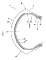
FIG. 1 is a cross-sectional view showing a motorcycle tire formed according to an embodiment of the present invention; -
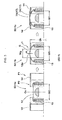
FIG. 2 shows views schematically illustrating a raw-tire-body forming process; -
FIG. 3 shows views schematically illustrating a belt-ply forming process; -
FIG. 4 shows views schematically illustrating a belt-ply forming process subsequent to the process shown inFIG. 3 ; and -
FIG. 5 shows views schematically illustrating a belt-ply forming process and a tread forming process subsequent to the process shown inFIG. 4 . - In the following, an embodiment of the present invention is described in detail.
- As shown in
FIG. 1 , motorcycle tire 1 formed by the manufacturing method of the present embodiment is provided withcarcass 6 extending fromtread section 2 throughsidewall 3 to reachbead core 5 inbead section 4, andbelt layer 7 positioned on the radially outer side ofcarcass 6 and on the inner side oftread section 2. - Tread (2S) that is the outer surface of
tread section 2 extends from tire equatorial plane (C) toward tread edges (Te) in a convex arc shape. In addition, the tread width measured between tread edges (Te, Te) is the tire maximum width in an axial direction, thus allowing the motorcycle to bank significantly when turning in a manner characteristic of motorcycles. -
Carcass 6 is made of one or more carcass plies (6A) formed by arranging carcass cords in an angle range of 65∼90 degrees with respect to a tire circumferential direction. In the present embodiment,carcass 6 is provided with one carcass ply (6A). Examples of carcass cords are preferred to be organic fiber cords such as nylon, polyester and rayon. In carcass ply (6A), on both ends of ply main body (6a) extended between bead cores (5, 5), ply turn-up portion (6b) is formed continuously from the main body to turn up aroundbead core 5 from the tire axially inner side toward the outer side and to be locked therein. Between ply main body (6a) and ply turn-up portion (6b), beadapex rubber 8 for reinforcing the bead is provided, tapering frombead core 5 in the tire radially outer direction. -
Belt layer 7 is made up of 2∼3 belt plies (7A) formed by arranging belt cords in an angle range of 10∼40 degrees with respect to a tire circumferential direction. In the present embodiment,belt layer 7 is provided with two belt plies (7A). Inclination directions of belt cords in belt plies (7A) are set opposite so that belt cords intersect each other when belt plies (7A) are laminated in a radial direction. Organic fiber cords such as aramid, nylon and rayon, especially aramid fiber cords, are preferred for belt cords, but steel cords may also be used. When steel cords or aramid fibers are used, belt ply (7A) exhibits significant binding force, and thereby further suppresses deformation intread section 2. - If applicable, a band layer (not shown) is formed on the tire radially outer side of
belt layer 7. A band layer is made up of one or more band plies formed by winding band cords helically in a tire circumferential direction, for example. Such a band layer suppressestread section 2 from lifting during high-speed rotations, while enhancing the rigidity oftread section 2 in a circumferential direction. As a result, durability and steering stability are enhanced during high-speed running. - In the following, a method for manufacturing a motorcycle tire is described according to an embodiment of the present invention. The manufacturing method of the present embodiment includes a raw-tire-body forming process and a vulcanization process to vulcanize the raw tire formed in the raw-tire-body forming process so that motorcycle tire 1 is obtained. The vulcanization may be conducted by any conventional vulcanization process. Thus, a description of such a process is omitted in the present application.
- As shown schematically in
FIGs. 2∼5 , a raw-tire-body forming process includes a raw-tire-body forming process (S1), a belt-ply forming process (S2), and a tread forming process (S3). -
FIG. 2 shows raw-tire-body forming process (S1). Any conventional method may be employed for raw-tire-body forming process (S1). A sheet-type carcass ply (6A) is wound in a circumferential direction of a raw tire on acylindrical molding drum 10, andbead core 5 is provided for each of both end portions. Accordingly, cylindricalraw tire body 12 which includescylindrical carcass body 11 is formed. The present embodiment shows an example wherecylindrical carcass body 11 is formed to have each end portion (11a) turned up aroundbead core 5 and locked therein. - Width (W0) of
molding drum 10 is set based on the profile of vulcanized motorcycle tire 1. Inraw tire body 12, known members such as an inner-liner rubber, sidewall rubber, clinch rubber and the like are laminated oncylindrical carcass body 11 where applicable. -
Raw tire body 12 is removed frommolding drum 10 by decreasing the diameter ofmolding drum 10. Then,raw tire body 12 is transferred to a pair of shaping drums (13, 13) (so-called second formers) as shown inFIGs. 3 to 5 . Next, first belt-ply forming process (S2-1), second belt-ply forming process (S2-2), and third belt-ply forming process (S2-3) are conducted in that order. Paired shaping drums (13, 13) each support the bead ofraw tire body 12, and are movable for a short distance toward both sides of the tire in axial directions with the tire equatorial plane set as the center of movement. -
FIG. 3 shows first belt-ply forming process (S2-1) and raw-tire-body forming process (S1a). In first belt-ply forming process (S2-1), a cylindrical belt ply 17 is obtained by winding a sheet-type belt ply (7A) in a cylindrical shape to be concentric withraw tire body 12 as shown inFIG. 3 . More specifically, first belt-ply forming process (S2-1) includes bell-ring closing step (S2-1a), first expansion step (S2-1b) and winding step (S2-1c). - In bell-ring closing step (S2-1a), the distance between shaping drums (13, 13), namely, the distance between a pair of bead cores (5, 5), is set to be equal to width (W0) of
molding drum 10, for example. - Next, in bell-ring closing step (S2-1a), a pair of cylindrical bell rings 14 concentric with shaping
drums 13 are used. Paired bell rings 14 are supported to be movable for a short distance toward both sides of the tire in axial directions with the tire equatorial plane set as the center of movement. - Paired bell rings (14, 14) are positioned in standby positions (P1) on the axially outer side of the tire. When bell-ring closing step (S2-1a) is initiated, paired bell rings 14 move from standby positions (P1) on the axially outer side toward close-in positions (P2) on the axially inner side of the tire. The width of gap (G) between paired bell rings (14, 14) in close-in positions (P2), namely, distance (Wg) between paired bell rings (14, 14), is preferred to be in a range of 50∼100 mm, for example.
- When above distance (Wg) is less than 50 mm, height (H) of apex (12p) of
raw tire body 12 protruding through gap (G) is insufficient in first expansion step (S2-1b). As a result, belt ply (7A) will not bond well withraw tire body 12 in winding step (S2-1c). - On the other hand, when above distance (Wg) exceeds 100 mm, height (H) of apex (12p) of
raw tire body 12 protruding through gap (G) is too great in first expansion step (S2-1b). Accordingly, belt ply (7A) does not abut bell rings (14, 14) sufficiently in winding step (S2-1c), and accuracy in the winding process of belt ply (7A) may decrease. - In first expansion step (S2-1b), the distance between bead cores (5, 5) is reduced to first distance (W1) that is smaller than above width (W0), while
raw tire body 12 is filled at a first inflation pressure. Accordingly,raw tire body 12 expands in the radially outward direction, causing the external peripheral surface ofraw tire body 12 to abut the inner circumferential surface of bell rings (14, 14). Moreover,raw tire body 12 keeps expanding until its apex (12p) protrudes in a radially outward direction through gap (G) between bell rings (14, 14) to have height (H) in a toroidal shape. At that time, the state ofraw tire body 12 and cylindrical belt ply 17 is referred to as first expanded phase (J1). In first expanded phase (J1), height (H) of apex (12p) ofraw tire body 12 is preferred to protrude by 5∼30 mm, for example, from the outer peripheral surface of bell rings (14, 14). - When the protrusion of height (H) of apex (12p) of
raw tire body 12 is less than 5 mm, belt ply (7A) andraw tire body 12 will bond sufficiently in the winding step (S2-1c). On the other hand, when the above protrusion of height (H) exceeds 30 mm, belt ply (7A) does not sufficiently abut bell rings (14, 14) in winding step (S2-1c). Thus, accuracy in winding belt ply (7A) may be lowered. - First distance (W1) between bead cores (5, 5) and first inflation pressure in
raw tire body 12 in first expansion step (S2-1b) are maintained until first expansion step (S2-2b) starts in second belt-ply forming process (S2-2) shown inFIG. 4 . - In winding step (S2-1c) subsequent to first expansion step (S2-1b), sheet-type belt ply (7A) is wound by being extended on bell rings (14, 14). Accordingly, cylindrical belt ply 17 is formed with its inner circumferential surface bonded to apex (12p) of
raw tire body 12. - If cylindrical belt ply 17 is first formed by being extended between bell rings (14, 14), and then
raw tire body 12 is expanded outward by inflation pressure,raw tire body 12 makes contact with cylindrical belt ply 17 during an unstable phase of the expansion process. Thus, the positional accuracy of cylindrical belt ply 17 with respect toraw tire body 12 may be reduced. Therefore, in first belt-ply forming process (S2-1), first expansion step (S2-1b) is preferred to be conducted first, followed by winding step (S2-1c). - As shown in
FIG. 4 , in second belt-ply forming process (S2-2),raw tire body 12 is further expanded in the radially outward direction so that cylindrical belt ply 17 andraw tire body 12 will be bonded in a wider range. More specifically, second belt-ply forming process (S2-2) includes bell-ring opening step (S2-2a), second expansion step (S2-2b) and third expansion step (S2-2c). - In bell-ring opening step (S2-2a), paired bell rings 14 move to standby positions (P1) (see
FIG. 3 ). Accordingly,raw tire body 12 and paired bell rings 14 are released from abutting, allowingraw tire body 12 to further expand in a radially outward direction. - In second expansion step (S2-2b), the distance between bead cores (5, 5) is reduced to second distance (W2) that is smaller than first distance (W1), while
raw tire body 12 is filled at a second inflation pressure that is higher than the first inflation pressure. Accordingly,raw tire body 12 expands in a radially outward direction. The state ofraw tire body 12 and cylindrical belt ply 17 at that time is referred to as second expanded phase (J2). Since uniform tensile force is exerted on the carcass ply when the raw tire body is filled at the second inflation pressure in second expansion step (S2-2b), angles of belt cords in the raw tire are maintained uniformly in a tire circumferential direction. - The second inflation pressure is preferred to be 150∼300 kPa. When the second inflation pressure is lower than 150 kPa,
raw tire body 12 and cylindrical belt ply 17 may not expand sufficiently in second expanded phase (J2). When the second inflation pressure exceeds 300 kPa,raw tire body 12 and cylindrical belt ply 17 may expand excessively in second expanded phase (J2). - The duration required for second expansion step (S2-2b), namely, the time needed to increase pressure from the first inflation pressure to the second inflation pressure, is preferred to be 10∼30 seconds. If the pressure boosting time is shorter than 10 seconds,
raw tire body 12 and cylindrical belt ply 17 may not expand sufficiently in second expanded phase (J2). On the other hand, if the pressure boosting time exceeds 30 seconds, productivity of raw tires may decrease. - It is an option for
raw tire body 12 to be filled at a second inflation pressure by simply filling the tire with air, or by filling air using a bladder provided on the radially inner side of the tire. Using the latter method, even when the rubber thickness, for example, the thickness of the inner-liner rubber, on the inner circumferential side of carcass ply (6A) is reduced, a second inflation pressure may be applied at a level necessary to maintain second expanded phase (J2) ofraw tire body 12 and cylindrical belt ply 17. As a result, both light weight and uniformity are achieved in the tire. - In third expansion step (S2-2c) following second expansion step (S2-2b),
expandable profile deck 15 is used.Profile deck 15 is positioned to be concentric with shapingdrums 13, and they are formed to be rotatable to synchronize at the same rotation speed. -
Profile deck 15 is formed to have the same structure as that disclosed inpatent publication 2 above, and has an external shape similar to the outline of the tire cavity of motorcycle tire 1. More specifically,profile deck 15 is formed to include multiple elements (15a) divided in a circumferential direction. When each element (15a) moves in a radially inner or outer direction by using a known expandable mechanism (not shown) such as a link mechanism or a cylinder,profile deck 15 enlarges or reduces its diameter. - In third expansion step (S2-2c), the distance between bead cores (5, 5) is reduced to third distance (W3) that is smaller than second distance (W2), while
profile deck 15 enlarges its diameter from standby position (P3) on the radially inner side ofraw tire body 12 toward radially outer expanded position (P4). Accordingly, the apex ofraw tire body 12 along with cylindrical belt ply 17 expands in the radially outward direction. The state ofraw tire body 12 and cylindrical belt ply 17 is referred to as third expanded phase (J3). - In third expansion step (S2-2c), the inflation pressure of
raw tire body 12 is reduced to its surrounding ambient pressure, for example, afterprofile deck 15 has enlarged its diameter to radially outer expanded position (P4). - In the present embodiment,
raw tire body 12 and cylindrical belt ply 17 are expanded in two steps, that is, filling the raw tire body at a second inflation pressure in second expansion step (S2-2b) followed by enlarging the diameter ofprofile deck 15 in third expansion step (S2-2c). Accordingly, even when steel or aramid fibers with strong binding force are used for belt cords, it is not necessary to exert strong drive force to enlarge the diameter ofprofile deck 15. - The same as the manufacturing method disclosed in patent publication 1 above, since
raw tire body 12 is expanded by filling it at the second inflation pressure in second expansion step (S2-2b), the profile of a raw tire in second expanded phase (J2) tends to be different from the profile of a vulcanization die. However, in the present embodiment, the profile of a raw tire is corrected to a shape approximating that of the vulcanization die whenprofile deck 15 enlarges its diameter in third expansion step (S2-2c). Accordingly, the rubber or belt cords are unlikely to move in the vulcanization die, thereby resulting in improved uniformity. - Meanwhile, the same as the manufacturing method disclosed in
patent publication 2 above, because of the diameter enlarging mechanism ofprofile deck 15 used for expandingraw tire 12, angles of belt cords tend to vary unevenly in a tire circumferential direction in third expansion step (S2-2c). However, in the present embodiment, becauseraw tire body 12 and cylindrical belt ply 17 have been expanded in second expansion step (S2-2b), the degree of expansion during third expansion step (S2-2c) is lower. Moreover, since circumferentially uniform expansion has been already achieved in second expansion step (S2-2b) as a result of the raw tire body being filled at the second inflation pressure, the angle variations of belt cords are limited in third expansion step (S2-2c). Therefore, uneven angles of belt cords in a tire circumferential direction are suppressed whenprofile deck 15 enlarges its diameter. Accordingly, uniformity is improved. - As shown in
FIG. 5 , in third belt-ply forming process (S2-3),raw tire body 12 and cylindrical belt ply 17 are completely bonded. Furthermore, in tread forming process (S3), a tread rubber is formed on the radially outer side of cylindrical belt ply 17. - Third belt-ply forming process (S2-3) includes belt bonding step (S2-3a). In belt bonding step (S2-3a), while the inner circumferential surface of
raw tire body 12 is supported byprofile deck 15, both edges of cylindrical belt ply 17 are wound down to be bonded to theraw tire body 12 expanded in a toroidal shape. Both edges are wound down whenstitch rollers 19 are pressed continuously along the outer peripheral surface of cylindrical belt ply 17 from the equator toward the axially outer side, while shapingdrums 13 andprofile deck 15 set to be concentric are rotated at the same rotation speed. Accordingly, cylindrical belt ply 17 is completely bonded toraw tire body 12 from the equator all the way to both edges. - After the above, a band ply is formed on the radially outer side of cylindrical belt ply 17.
- In tread forming process (S3), tread
rubber member 20, which is extruded and molded to have a wide belt shape with a trapezoidal cross section, is laminated on the radially outer side of cylindrical belt ply 17 to form a tread rubber. Treadrubber 20 is formed in a cylindrical shape by being wound once in a circumferential direction onto the outer circumferential surface of cylindrical belt ply 17, and is curved along cylindrical belt ply 17 by stitching downward usingstitch rollers 19 or the like. Accordingly, a tread rubber is obtained. - In tread forming process (S3), a so-called strip wind method (STW method) may also be employed. In such an STW method, a tread rubber is formed by helically winding narrow tape-shaped rubber strips (not shown) continuously on cylindrical belt ply 17.
- Internal diameter (Dc) on equatorial plane (C) of cylindrical belt ply 17 after belt bonding step (S2-3a) shown in
FIG. 5 is conducted is greater than external diameter (Db) of the bell rings shown inFIG. 3 . On the other hand, internal diameter (Ds) at the axial edge of cylindrical belt ply 17 after belt bonding step (S2-3a) shown inFIG. 5 is conducted is preferred to be smaller than external diameter (Db) of the bell rings. By so setting, even when its diameter changes, angular variations in cylindrical belt ply 17 are suppressed, and tire uniformity is enhanced. - Moreover, internal diameter (Dc), external diameter (Db) and internal diameter (Ds) above are preferred to satisfy the following relationship.

- When the above ratio (Db-Ds) / (Dc-Ds) is less than 0.15, that would cause a greater angular change in belt cords near equator (C) of a raw tire, and it is difficult to expand cylindrical belt ply 17. On the other hand, when the above ratio (Db-Ds) / (Dc-Ds) exceeds 0.45, that would cause a greater angular change in belt cords near both edges of cylindrical belt ply 17 of a raw tire. Accordingly, wrinkles may occur near both edges of cylindrical belt ply 17 and uniformity may decrease.
- As shown in
FIG. 4 , external diameter (D2) on equator (C) of cylindrical belt ply 17 in second expanded phase (J2) and external diameter (D3) on equator (C) of cylindrical belt ply 17 in third expanded phase (J3) are preferred to have a ratio (D2/D3) in a range of 0.90∼1.00. - When the above ratio (D2/D3) is smaller than 0.90, the diameter change of cylindrical belt ply 17 in third expansion step (S2-2c) increases, and that would make it harder to expand cylindrical belt ply 17. Also, since the degree of expanding cylindrical belt ply 17 by using
profile deck 15 increases, angles of belt cords tend to vary unevenly in a tire circumferential direction, and uniformity may be reduced accordingly. - On the other hand, when the above ratio (D2/D3) exceeds 1.00, the effect achieved when
profile deck 15 corrects the profile of a raw tire will be limited. Thus, the effort to enhance uniformity may fail. - So far, an especially preferred embodiment of the present invention has been described in detail. However, the present invention is not limited to the above, and various modifications of the embodiment are possible.
- Test motorcycle tires in size 120/70ZR17 with a basic structure as shown in
FIG. 1 are each manufactured to have specifications in Table 1, and uniformity in each tire was measured. - To make a comparison, test motorcycle tires having the same structure as above were prepared according to the manufacturing method shown in patent publication 1 (comparative example 1), the manufacturing method shown in patent publication 2 (comparative example 2), and a manufacturing method of the embodiment above from which a second expansion step is omitted (comparative example 3) respectively, and uniformity in each tire was also measured.
- In all the test tires, a belt layer is formed with two belt plies each prepared by arranging a 3x3 steel cord (line diameter of 0.17 mm) with a cord count of 55/50 mm at an angle of 27 degrees.
- Twenty tires are each picked at random from the tires manufactured by their respective methods and mounted on a rim MT3.50×17 under conditions of an inflation pressure of 200 kPa and a load of 1.45 kN. Then, radial force variation (RFV), lateral force variation (LFV), radial run-out (RRO) and lateral run-out (LRO) of each tire are measured respectively. In the LRO, "LRO T" indicates the LRO in the shoulder molded in the upper die of a vertically divided die, and "LRO B" indicates the LRO in the shoulder molded in the bottom die of a vertically divided die. Measurements are conducted according to the uniformity testing method specified in "JASOC 607:2000" and the values indicate average values. The smaller the value is, the more excellent is the uniformity.


- As is clear in Table 1, it was confirmed that motorcycle tires in the examples manufactured by the method according to the embodiment showed significantly enhanced uniformity, compared with those in the comparative examples.
After a cylindrical belt ply 17 is formed on the apex of araw tire body 12, while the distance between bead cores (5, 5) is reduced to a second distance (W2), the apex of theraw tire body 12 along with the cylindrical belt ply 17 is expanded to a second expanded phase (J2) by filling theraw tire body 12 at a second inflation pressure. Moreover, the apex of theraw tire body 12 along with the cylindrical belt ply 17 is expanded to a third expanded phase (J3) by increasing the diameter of aprofile deck 15 from a standby position (P3) on the radially inner side toward a radially outer expanded position (P4) of theraw tire body 12, while the distance between bead cores (5, 5) is reduced to a third distance (W3). - To provide a method for manufacturing a motorcycle tire capable of keeping belt cords from meandering so as to enhance uniformity.
- After a cylindrical belt ply 17 is formed on the apex of a
raw tire body 12, while the distance between bead cores (5, 5) is reduced to a second distance (W2), the apex of theraw tire body 12 along with the cylindrical belt ply 17 is expanded to a second expanded phase (J2) by filling theraw tire body 12 at a second inflation pressure. Moreover, the apex of theraw tire body 12 along with the cylindrical belt ply 17 is expanded to a third expanded phase (J3) by increasing the diameter of aprofile deck 15 from a standby position (P3) on the radially inner side toward a radially outer expanded position (P4) of theraw tire body 12, while the distance between bead cores (5, 5) is reduced to a third distance (W3). -
- 1
- motorcycle tire
- 2
- tread section
- 3
- sidewall
- 4
- bead section
- 5
- bead core
- 6
- carcass
- 7
- belt layer
- 7A
- belt ply
- 11
- cylindrical carcass body
- 12
- raw tire body
- 12p
- apex
- 14
- bell ring
- 15
- profile deck
- 17
- cylindrical belt ply
- C
- tire equatorial plane
- G
- gap
- J1
- first expanded phase
- J2
- second expanded phase
- J3
- third expanded phase
Claims (15)
- A method for manufacturing a motorcycle tire, the motorcycle tire being configured to have a carcass extending from the tread section through a sidewall to reach the bead core of a bead section, and a belt layer positioned on the radially outer side of the carcass and on the inner side of the tread section, where the belt layer is formed with a belt ply made of a plurality of belt cords, comprising:a raw-tire-body forming process to form a cylindrical raw tire body that contains a cylindrical carcass body in which a sheet-type carcass ply of the carcass is wound to be cylindrical, and bead cores are provided on both edges of the carcass ply; anda belt-ply forming process to form a cylindrical belt ply that is wound in a cylindrical shape,wherein the belt-ply forming process includes a bell-ring closing step to move a pair of cylindrical bell rings, which are supported to be movable for a short distance toward both sides of the tire in axial directions with the tire equatorial plane set as the center of movement and are positioned on the outside of the raw tire body to be concentric with the tire, from a standby position on the axially outer side toward the axially inner side of the tire leaving a gap in between;a first expansion step to expand the raw tire body in a toroidal shape by filling the raw tire body at a first inflation pressure, while reducing the distance between the bead cores to a first distance so that the apex of the raw tire body protrudes in the radially outward direction through the gap left between the paired bell rings;a winding step to wind a sheet-type belt ply by extending it on the pair of bell rings so as to form a cylindrical belt ply with its inner circumferential surface bonded to the apex of the raw tire body;after the paired bell rings are returned to the standby positions, a second expansion step to expand the apex of the raw tire body along with the cylindrical belt ply from the first expanded phase to a second expanded phase by filling the raw tire body at a second inflation pressure that is higher than the first inflation pressure, while reducing the distance between the bead cores to a second distance that is smaller than the first distance;a third expansion step to expand the apex of the raw tire body along with the cylindrical belt ply from the second expanded phase to a third expanded phase by increasing the diameter of an expandable profile deck from a standby position on the radially inner side to the radially outer expanded position of the raw tire body, while reducing the distance between the bead cores to a third distance that is smaller than the second distance; anda belt bonding step to bond the belt ply to the raw tire body by winding down both edges of the cylindrical belt ply.
- The manufacturing method according to Claim 1, wherein the second inflation pressure is set at 150 to 300 kPa.
- The manufacturing method according to Claim 1 or 2, wherein the time for increasing from the first inflation pressure to the second inflation pressure is set for 10 to 30 seconds.
- The manufacturing method according to any of Claims 1 to 3, wherein the internal diameter (Dc) on the equator of the cylindrical belt ply after the belt bonding step is conducted is set greater than the external diameter (Db) of the bell rings, and the internal diameter (Ds) at an axially peripheral edge of the cylindrical belt ply after the belt bonding step is conducted is set smaller than the external diameter (Db) of the bell rings.
- The manufacturing method according to Claim 4, wherein the internal diameter (Dc) on the equator of the cylindrical belt ply, the external diameter (Db) of the bell rings, and the internal diameter (Ds) at an axially peripheral edge of the cylindrical belt ply satisfy the following relationship.

- The manufacturing method according to any of Claims 1 to 5, wherein the belt cords are made of aramid fiber or steel.
- The manufacturing method according to any of Claims 1 to 6, wherein the second inflation pressure is filled into a bladder provided on the radially inner side of the raw tire body.
- The manufacturing method according to any of Claims 1 to 7, wherein the external diameter (D2) on the equator of the cylindrical belt ply in the second expanded phase and the external diameter (D3) on the equator of the cylindrical belt ply in the third expanded phase are set to have a ratio (D2/D3) in a range of 0.90 to 1.00.
- A method for manufacturing a motorcycle tire, the motorcycle tire being configured to have a carcass extending from the tread section through a sidewall to reach the bead core of a bead section, and a belt layer positioned on the radially outer side of the carcass and on the inner side of the tread section, where the belt layer is formed with a belt ply made of a plurality of belt cords, comprising:forming (S2-1, S2-2) a cylindrical belt ply (17) on the apex of a raw tire body (12), while the distance between bead cores (5, 5) is reduced to a second distance (W2),expanding the apex of the raw tire body (12) along with the cylindrical belt ply (17) to a second expanded phase (J2) by filling the raw tire body (12) at a second inflation pressure, andexpanding the apex of the raw tire body (12) along with the cylindrical belt ply (17) to a third expanded phase (J3) by increasing the diameter of a profile deck (15) from a standby position (P3) on the radially inner side toward a radially outer expanded position (P4) of the raw tire body (12), while the distance between bead cores (5, 5) is reduced to a third distance (W3).
- The manufacturing method according to claim 9, wherein the step of forming (S2-1, S2-2) the belt ply includes a first belt-ply forming process (S2-1) which includes bell-ring closing step (S2-1a) in which two bell-rings (14, 14) are moved toward each other in the axial direction of the tire, a first expansion step (S2-1b) and a winding step (S2-1c).
- The manufacturing method according to any of Claims 1 to 10, wherein a width (Wg) of a gap (G) between paired bell rings (14, 14) in close-in positions (P2) is in a range of 50 to 100 mm.
- The manufacturing method according to any of Claims 1 to 11, wherein, in first expansion step (S2-1b), the first inflation pressure is selected such that the raw tire body (12) expands until its apex (12p) protrudes in a radially outward direction through gap (G) between bell rings (14, 14) to have height (H) in a toroidal shape, wherein the height (H) is preferably 5 to 30 mm from the outer peripheral surface of bell rings (14, 14).
- The manufacturing method according to claims 9 to 12, wherein the step of forming (S2-1, S2-2) the belt ply includes further includes a second belt-ply forming process (S2-2) which includes a bell-ring opening step (S2-2a), a second expansion step (S2-2b) and a third expansion step (S2-2c).
- The manufacturing method according to claim 13, wherein, in the bell-ring opening step (S2-2a), paired bell rings 14 move to standby positions (P1) so as to be released from abutting, allowing raw tire body (12) to further expand in a radially outward direction, and,
in second expansion step (S2-2b), the distance between bead cores (5, 5) is reduced to second distance (W2) that is smaller than first distance (W1), while raw tire body (12) is filled at a second inflation pressure that is higher than the first inflation pressure. - The manufacturing method according to any of Claims 1 to 14, wherein the carcass cords are organic fiber cords such as preferably nylon, polyester and rayon.
Applications Claiming Priority (1)
| Application Number | Priority Date | Filing Date | Title |
|---|---|---|---|
| JP2014062422A JP6200360B2 (en) | 2014-03-25 | 2014-03-25 | Method for manufacturing motorcycle tire |
Publications (2)
| Publication Number | Publication Date |
|---|---|
| EP2923827A1 true EP2923827A1 (en) | 2015-09-30 |
| EP2923827B1 EP2923827B1 (en) | 2016-11-02 |
Family
ID=53008266
Family Applications (1)
| Application Number | Title | Priority Date | Filing Date |
|---|---|---|---|
| EP15160015.2A Not-in-force EP2923827B1 (en) | 2014-03-25 | 2015-03-20 | Method for manufacturing a motorcycle tire |
Country Status (3)
| Country | Link |
|---|---|
| US (1) | US9937678B2 (en) |
| EP (1) | EP2923827B1 (en) |
| JP (1) | JP6200360B2 (en) |
Cited By (2)
| Publication number | Priority date | Publication date | Assignee | Title |
|---|---|---|---|---|
| CN109278477A (en) * | 2018-08-02 | 2019-01-29 | 中策橡胶集团有限公司 | The determination method of heavy-duty pneumatic tire belt structure and the belt drum shape |
| WO2025032417A1 (en) * | 2023-08-08 | 2025-02-13 | Pirelli Tyre S.P.A. | Method and station for building a multilayer component for building a green tyre |
Families Citing this family (5)
| Publication number | Priority date | Publication date | Assignee | Title |
|---|---|---|---|---|
| EP3074216B1 (en) | 2013-11-26 | 2019-05-15 | Pirelli Tyre S.p.A. | Method and plant for building tyres |
| JP6510309B2 (en) * | 2015-05-11 | 2019-05-08 | Toyo Tire株式会社 | Method of manufacturing pneumatic tire, and shaping apparatus |
| JP6510308B2 (en) * | 2015-05-11 | 2019-05-08 | Toyo Tire株式会社 | Method of manufacturing pneumatic tire, and shaping apparatus |
| JP6533692B2 (en) * | 2015-05-11 | 2019-06-19 | Toyo Tire株式会社 | Method of manufacturing pneumatic tire, and shaping apparatus |
| MX2018007498A (en) * | 2015-12-28 | 2018-09-18 | Pirelli | Process and plant for building tyres. |
Citations (9)
| Publication number | Priority date | Publication date | Assignee | Title |
|---|---|---|---|---|
| US3966536A (en) * | 1973-05-15 | 1976-06-29 | Dunlop Limited | Tire building machinery |
| GB2118111A (en) * | 1982-02-17 | 1983-10-26 | Toyo Tire & Rubber Co | Process for making a radial tyre |
| JPH08174710A (en) * | 1994-12-20 | 1996-07-09 | Bridgestone Corp | Forming method of belt and tread assembly for radial tire |
| JP2002067184A (en) * | 2000-09-01 | 2002-03-05 | Sumitomo Rubber Ind Ltd | Tire manufacturing method |
| JP2003118011A (en) * | 2001-10-10 | 2003-04-23 | Sumitomo Rubber Ind Ltd | Manufacturing method and device for pneumatic tire |
| JP2004249496A (en) * | 2003-02-18 | 2004-09-09 | Sumitomo Rubber Ind Ltd | Manufacturing method and device for pneumatic tire |
| JP2005212278A (en) | 2004-01-29 | 2005-08-11 | Sumitomo Rubber Ind Ltd | Tire manufacturing method |
| EP1724099A1 (en) * | 2004-03-05 | 2006-11-22 | Bridgestone Corporation | Tire molding drum, and molding system, process designing method, and manufacturing method for tire molded by the tire molding drum |
| JP2007076182A (en) | 2005-09-14 | 2007-03-29 | Sumitomo Rubber Ind Ltd | Manufacturing method of radial tire for motorcycle |
Family Cites Families (9)
| Publication number | Priority date | Publication date | Assignee | Title |
|---|---|---|---|---|
| US2045545A (en) * | 1933-10-30 | 1936-06-23 | Nat Standard Co | Process and apparatus for making drum built tires |
| US2814331A (en) * | 1956-04-20 | 1957-11-26 | Vanzo Marcello | Process for building pneumatic tires |
| JPS533479A (en) * | 1976-07-01 | 1978-01-13 | Yokohama Rubber Co Ltd | Method of molding radial tire and air bladder for the molding |
| JPS595047A (en) * | 1982-07-01 | 1984-01-11 | Toyo Tire & Rubber Co Ltd | Forming machine for tire |
| EP0463875B1 (en) * | 1990-06-27 | 1995-04-12 | Sumitomo Rubber Industries, Co. Ltd | Motorcycle radial tyre |
| JP4305607B2 (en) * | 2002-02-13 | 2009-07-29 | 横浜ゴム株式会社 | Secondary molding method of radial tire |
| DE60323547D1 (en) * | 2003-11-28 | 2008-10-23 | Pirelli | METHOD FOR PRODUCING AIR TIRES AND TORUM CORE FOR IMPLEMENTING THE PROCESS. |
| EP1728609A4 (en) * | 2004-03-22 | 2008-12-17 | Bridgestone Corp | Method of vulcanization molding of rubber material |
| US20120067476A1 (en) * | 2010-09-20 | 2012-03-22 | Serge Julien Auguste Imhoff | Pneumatic tire and method for making a pneumatic tire |
-
2014
- 2014-03-25 JP JP2014062422A patent/JP6200360B2/en not_active Expired - Fee Related
-
2015
- 2015-03-20 EP EP15160015.2A patent/EP2923827B1/en not_active Not-in-force
- 2015-03-25 US US14/667,822 patent/US9937678B2/en not_active Expired - Fee Related
Patent Citations (9)
| Publication number | Priority date | Publication date | Assignee | Title |
|---|---|---|---|---|
| US3966536A (en) * | 1973-05-15 | 1976-06-29 | Dunlop Limited | Tire building machinery |
| GB2118111A (en) * | 1982-02-17 | 1983-10-26 | Toyo Tire & Rubber Co | Process for making a radial tyre |
| JPH08174710A (en) * | 1994-12-20 | 1996-07-09 | Bridgestone Corp | Forming method of belt and tread assembly for radial tire |
| JP2002067184A (en) * | 2000-09-01 | 2002-03-05 | Sumitomo Rubber Ind Ltd | Tire manufacturing method |
| JP2003118011A (en) * | 2001-10-10 | 2003-04-23 | Sumitomo Rubber Ind Ltd | Manufacturing method and device for pneumatic tire |
| JP2004249496A (en) * | 2003-02-18 | 2004-09-09 | Sumitomo Rubber Ind Ltd | Manufacturing method and device for pneumatic tire |
| JP2005212278A (en) | 2004-01-29 | 2005-08-11 | Sumitomo Rubber Ind Ltd | Tire manufacturing method |
| EP1724099A1 (en) * | 2004-03-05 | 2006-11-22 | Bridgestone Corporation | Tire molding drum, and molding system, process designing method, and manufacturing method for tire molded by the tire molding drum |
| JP2007076182A (en) | 2005-09-14 | 2007-03-29 | Sumitomo Rubber Ind Ltd | Manufacturing method of radial tire for motorcycle |
Cited By (2)
| Publication number | Priority date | Publication date | Assignee | Title |
|---|---|---|---|---|
| CN109278477A (en) * | 2018-08-02 | 2019-01-29 | 中策橡胶集团有限公司 | The determination method of heavy-duty pneumatic tire belt structure and the belt drum shape |
| WO2025032417A1 (en) * | 2023-08-08 | 2025-02-13 | Pirelli Tyre S.P.A. | Method and station for building a multilayer component for building a green tyre |
Also Published As
| Publication number | Publication date |
|---|---|
| US9937678B2 (en) | 2018-04-10 |
| US20150273777A1 (en) | 2015-10-01 |
| EP2923827B1 (en) | 2016-11-02 |
| JP2015182382A (en) | 2015-10-22 |
| JP6200360B2 (en) | 2017-09-20 |
Similar Documents
| Publication | Publication Date | Title |
|---|---|---|
| EP2923827B1 (en) | Method for manufacturing a motorcycle tire | |
| JP4695429B2 (en) | Pneumatic tire and manufacturing method thereof | |
| JP4630096B2 (en) | Motorcycle tires | |
| JP5080871B2 (en) | Pneumatic tire and manufacturing method thereof | |
| JP4294803B2 (en) | Manufacturing method of carcass structure of automobile tire and carcass structure of automobile wheel tire | |
| US10259181B2 (en) | Sleeveless tire building drum | |
| JPH04232035A (en) | Manufacture of tire for vehicle wheel and said tire | |
| US20050028920A1 (en) | High crown first stage tire building drum | |
| US11001022B2 (en) | Method for manufacturing motorcycle tire | |
| US20140048213A1 (en) | Sleeveless tire building drum with interchangeable width elements | |
| EP1488914B1 (en) | Method for manufacturing pneumatic tire | |
| JP4914508B2 (en) | Manufacturing method of raw tire for motorcycle | |
| EP2181838A1 (en) | A bladder, an apparatus and a method for shaping and curing a tire | |
| US20100269976A1 (en) | Process and plant for building tyres for vehicle wheels | |
| CN109421302B (en) | Method of building a tyre | |
| US7850808B2 (en) | Pneumatic tire and producing method of pneumatic tire | |
| US11548250B2 (en) | Method and device for forming pneumatic tire | |
| JP2007276268A (en) | Pneumatic tire manufacturing method | |
| US10328651B2 (en) | Rigid core mold and method for manufacturing pneumatic tire using the same | |
| US7896996B2 (en) | Pneumatic tire and producing method of pneumatic tire | |
| JP4261937B2 (en) | Pneumatic tire manufacturing method and apparatus | |
| JP2005212278A (en) | Tire manufacturing method | |
| JP3124931B2 (en) | Manufacturing method of radial tire | |
| JP2007076182A (en) | Manufacturing method of radial tire for motorcycle | |
| CN106142609B (en) | Method for manufacturing pneumatic tire, molding device, and pneumatic tire |
Legal Events
| Date | Code | Title | Description |
|---|---|---|---|
| PUAI | Public reference made under article 153(3) epc to a published international application that has entered the european phase |
Free format text: ORIGINAL CODE: 0009012 |
|
| AK | Designated contracting states |
Kind code of ref document: A1 Designated state(s): AL AT BE BG CH CY CZ DE DK EE ES FI FR GB GR HR HU IE IS IT LI LT LU LV MC MK MT NL NO PL PT RO RS SE SI SK SM TR |
|
| AX | Request for extension of the european patent |
Extension state: BA ME |
|
| 17P | Request for examination filed |
Effective date: 20150903 |
|
| GRAP | Despatch of communication of intention to grant a patent |
Free format text: ORIGINAL CODE: EPIDOSNIGR1 |
|
| INTG | Intention to grant announced |
Effective date: 20160817 |
|
| GRAS | Grant fee paid |
Free format text: ORIGINAL CODE: EPIDOSNIGR3 |
|
| GRAA | (expected) grant |
Free format text: ORIGINAL CODE: 0009210 |
|
| AK | Designated contracting states |
Kind code of ref document: B1 Designated state(s): AL AT BE BG CH CY CZ DE DK EE ES FI FR GB GR HR HU IE IS IT LI LT LU LV MC MK MT NL NO PL PT RO RS SE SI SK SM TR |
|
| REG | Reference to a national code |
Ref country code: GB Ref legal event code: FG4D |
|
| REG | Reference to a national code |
Ref country code: AT Ref legal event code: REF Ref document number: 841395 Country of ref document: AT Kind code of ref document: T Effective date: 20161115 Ref country code: CH Ref legal event code: EP |
|
| REG | Reference to a national code |
Ref country code: IE Ref legal event code: FG4D |
|
| REG | Reference to a national code |
Ref country code: DE Ref legal event code: R096 Ref document number: 602015000579 Country of ref document: DE |
|
| PG25 | Lapsed in a contracting state [announced via postgrant information from national office to epo] |
Ref country code: LV Free format text: LAPSE BECAUSE OF FAILURE TO SUBMIT A TRANSLATION OF THE DESCRIPTION OR TO PAY THE FEE WITHIN THE PRESCRIBED TIME-LIMIT Effective date: 20161102 |
|
| REG | Reference to a national code |
Ref country code: NL Ref legal event code: MP Effective date: 20161102 |
|
| REG | Reference to a national code |
Ref country code: LT Ref legal event code: MG4D |
|
| REG | Reference to a national code |
Ref country code: AT Ref legal event code: MK05 Ref document number: 841395 Country of ref document: AT Kind code of ref document: T Effective date: 20161102 |
|
| REG | Reference to a national code |
Ref country code: FR Ref legal event code: PLFP Year of fee payment: 3 |
|
| PG25 | Lapsed in a contracting state [announced via postgrant information from national office to epo] |
Ref country code: NO Free format text: LAPSE BECAUSE OF FAILURE TO SUBMIT A TRANSLATION OF THE DESCRIPTION OR TO PAY THE FEE WITHIN THE PRESCRIBED TIME-LIMIT Effective date: 20170202 Ref country code: NL Free format text: LAPSE BECAUSE OF FAILURE TO SUBMIT A TRANSLATION OF THE DESCRIPTION OR TO PAY THE FEE WITHIN THE PRESCRIBED TIME-LIMIT Effective date: 20161102 Ref country code: GR Free format text: LAPSE BECAUSE OF FAILURE TO SUBMIT A TRANSLATION OF THE DESCRIPTION OR TO PAY THE FEE WITHIN THE PRESCRIBED TIME-LIMIT Effective date: 20170203 Ref country code: LT Free format text: LAPSE BECAUSE OF FAILURE TO SUBMIT A TRANSLATION OF THE DESCRIPTION OR TO PAY THE FEE WITHIN THE PRESCRIBED TIME-LIMIT Effective date: 20161102 Ref country code: SE Free format text: LAPSE BECAUSE OF FAILURE TO SUBMIT A TRANSLATION OF THE DESCRIPTION OR TO PAY THE FEE WITHIN THE PRESCRIBED TIME-LIMIT Effective date: 20161102 |
|
| PG25 | Lapsed in a contracting state [announced via postgrant information from national office to epo] |
Ref country code: ES Free format text: LAPSE BECAUSE OF FAILURE TO SUBMIT A TRANSLATION OF THE DESCRIPTION OR TO PAY THE FEE WITHIN THE PRESCRIBED TIME-LIMIT Effective date: 20161102 Ref country code: AT Free format text: LAPSE BECAUSE OF FAILURE TO SUBMIT A TRANSLATION OF THE DESCRIPTION OR TO PAY THE FEE WITHIN THE PRESCRIBED TIME-LIMIT Effective date: 20161102 Ref country code: RS Free format text: LAPSE BECAUSE OF FAILURE TO SUBMIT A TRANSLATION OF THE DESCRIPTION OR TO PAY THE FEE WITHIN THE PRESCRIBED TIME-LIMIT Effective date: 20161102 Ref country code: HR Free format text: LAPSE BECAUSE OF FAILURE TO SUBMIT A TRANSLATION OF THE DESCRIPTION OR TO PAY THE FEE WITHIN THE PRESCRIBED TIME-LIMIT Effective date: 20161102 Ref country code: IS Free format text: LAPSE BECAUSE OF FAILURE TO SUBMIT A TRANSLATION OF THE DESCRIPTION OR TO PAY THE FEE WITHIN THE PRESCRIBED TIME-LIMIT Effective date: 20170302 Ref country code: PT Free format text: LAPSE BECAUSE OF FAILURE TO SUBMIT A TRANSLATION OF THE DESCRIPTION OR TO PAY THE FEE WITHIN THE PRESCRIBED TIME-LIMIT Effective date: 20170302 Ref country code: FI Free format text: LAPSE BECAUSE OF FAILURE TO SUBMIT A TRANSLATION OF THE DESCRIPTION OR TO PAY THE FEE WITHIN THE PRESCRIBED TIME-LIMIT Effective date: 20161102 Ref country code: PL Free format text: LAPSE BECAUSE OF FAILURE TO SUBMIT A TRANSLATION OF THE DESCRIPTION OR TO PAY THE FEE WITHIN THE PRESCRIBED TIME-LIMIT Effective date: 20161102 |
|
| PG25 | Lapsed in a contracting state [announced via postgrant information from national office to epo] |
Ref country code: DK Free format text: LAPSE BECAUSE OF FAILURE TO SUBMIT A TRANSLATION OF THE DESCRIPTION OR TO PAY THE FEE WITHIN THE PRESCRIBED TIME-LIMIT Effective date: 20161102 Ref country code: RO Free format text: LAPSE BECAUSE OF FAILURE TO SUBMIT A TRANSLATION OF THE DESCRIPTION OR TO PAY THE FEE WITHIN THE PRESCRIBED TIME-LIMIT Effective date: 20161102 Ref country code: SK Free format text: LAPSE BECAUSE OF FAILURE TO SUBMIT A TRANSLATION OF THE DESCRIPTION OR TO PAY THE FEE WITHIN THE PRESCRIBED TIME-LIMIT Effective date: 20161102 Ref country code: EE Free format text: LAPSE BECAUSE OF FAILURE TO SUBMIT A TRANSLATION OF THE DESCRIPTION OR TO PAY THE FEE WITHIN THE PRESCRIBED TIME-LIMIT Effective date: 20161102 Ref country code: CZ Free format text: LAPSE BECAUSE OF FAILURE TO SUBMIT A TRANSLATION OF THE DESCRIPTION OR TO PAY THE FEE WITHIN THE PRESCRIBED TIME-LIMIT Effective date: 20161102 |
|
| REG | Reference to a national code |
Ref country code: DE Ref legal event code: R097 Ref document number: 602015000579 Country of ref document: DE |
|
| PG25 | Lapsed in a contracting state [announced via postgrant information from national office to epo] |
Ref country code: SM Free format text: LAPSE BECAUSE OF FAILURE TO SUBMIT A TRANSLATION OF THE DESCRIPTION OR TO PAY THE FEE WITHIN THE PRESCRIBED TIME-LIMIT Effective date: 20161102 Ref country code: BE Free format text: LAPSE BECAUSE OF FAILURE TO SUBMIT A TRANSLATION OF THE DESCRIPTION OR TO PAY THE FEE WITHIN THE PRESCRIBED TIME-LIMIT Effective date: 20161102 Ref country code: IT Free format text: LAPSE BECAUSE OF FAILURE TO SUBMIT A TRANSLATION OF THE DESCRIPTION OR TO PAY THE FEE WITHIN THE PRESCRIBED TIME-LIMIT Effective date: 20161102 Ref country code: BG Free format text: LAPSE BECAUSE OF FAILURE TO SUBMIT A TRANSLATION OF THE DESCRIPTION OR TO PAY THE FEE WITHIN THE PRESCRIBED TIME-LIMIT Effective date: 20170202 |
|
| PLBE | No opposition filed within time limit |
Free format text: ORIGINAL CODE: 0009261 |
|
| STAA | Information on the status of an ep patent application or granted ep patent |
Free format text: STATUS: NO OPPOSITION FILED WITHIN TIME LIMIT |
|
| 26N | No opposition filed |
Effective date: 20170803 |
|
| PG25 | Lapsed in a contracting state [announced via postgrant information from national office to epo] |
Ref country code: MC Free format text: LAPSE BECAUSE OF FAILURE TO SUBMIT A TRANSLATION OF THE DESCRIPTION OR TO PAY THE FEE WITHIN THE PRESCRIBED TIME-LIMIT Effective date: 20161102 Ref country code: SI Free format text: LAPSE BECAUSE OF FAILURE TO SUBMIT A TRANSLATION OF THE DESCRIPTION OR TO PAY THE FEE WITHIN THE PRESCRIBED TIME-LIMIT Effective date: 20161102 |
|
| REG | Reference to a national code |
Ref country code: IE Ref legal event code: MM4A |
|
| PG25 | Lapsed in a contracting state [announced via postgrant information from national office to epo] |
Ref country code: LU Free format text: LAPSE BECAUSE OF NON-PAYMENT OF DUE FEES Effective date: 20170320 |
|
| REG | Reference to a national code |
Ref country code: FR Ref legal event code: PLFP Year of fee payment: 4 |
|
| PG25 | Lapsed in a contracting state [announced via postgrant information from national office to epo] |
Ref country code: IE Free format text: LAPSE BECAUSE OF NON-PAYMENT OF DUE FEES Effective date: 20170320 |
|
| PG25 | Lapsed in a contracting state [announced via postgrant information from national office to epo] |
Ref country code: MT Free format text: LAPSE BECAUSE OF NON-PAYMENT OF DUE FEES Effective date: 20170320 |
|
| REG | Reference to a national code |
Ref country code: CH Ref legal event code: PL |
|
| PG25 | Lapsed in a contracting state [announced via postgrant information from national office to epo] |
Ref country code: CH Free format text: LAPSE BECAUSE OF NON-PAYMENT OF DUE FEES Effective date: 20180331 Ref country code: LI Free format text: LAPSE BECAUSE OF NON-PAYMENT OF DUE FEES Effective date: 20180331 |
|
| PG25 | Lapsed in a contracting state [announced via postgrant information from national office to epo] |
Ref country code: HU Free format text: LAPSE BECAUSE OF FAILURE TO SUBMIT A TRANSLATION OF THE DESCRIPTION OR TO PAY THE FEE WITHIN THE PRESCRIBED TIME-LIMIT; INVALID AB INITIO Effective date: 20150320 |
|
| PG25 | Lapsed in a contracting state [announced via postgrant information from national office to epo] |
Ref country code: CY Free format text: LAPSE BECAUSE OF FAILURE TO SUBMIT A TRANSLATION OF THE DESCRIPTION OR TO PAY THE FEE WITHIN THE PRESCRIBED TIME-LIMIT Effective date: 20161102 |
|
| GBPC | Gb: european patent ceased through non-payment of renewal fee |
Effective date: 20190320 |
|
| PG25 | Lapsed in a contracting state [announced via postgrant information from national office to epo] |
Ref country code: MK Free format text: LAPSE BECAUSE OF FAILURE TO SUBMIT A TRANSLATION OF THE DESCRIPTION OR TO PAY THE FEE WITHIN THE PRESCRIBED TIME-LIMIT Effective date: 20161102 |
|
| PG25 | Lapsed in a contracting state [announced via postgrant information from national office to epo] |
Ref country code: GB Free format text: LAPSE BECAUSE OF NON-PAYMENT OF DUE FEES Effective date: 20190320 |
|
| PG25 | Lapsed in a contracting state [announced via postgrant information from national office to epo] |
Ref country code: TR Free format text: LAPSE BECAUSE OF FAILURE TO SUBMIT A TRANSLATION OF THE DESCRIPTION OR TO PAY THE FEE WITHIN THE PRESCRIBED TIME-LIMIT Effective date: 20161102 |
|
| PG25 | Lapsed in a contracting state [announced via postgrant information from national office to epo] |
Ref country code: AL Free format text: LAPSE BECAUSE OF FAILURE TO SUBMIT A TRANSLATION OF THE DESCRIPTION OR TO PAY THE FEE WITHIN THE PRESCRIBED TIME-LIMIT Effective date: 20161102 |
|
| P01 | Opt-out of the competence of the unified patent court (upc) registered |
Effective date: 20230510 |
|
| PGFP | Annual fee paid to national office [announced via postgrant information from national office to epo] |
Ref country code: DE Payment date: 20240130 Year of fee payment: 10 |
|
| PGFP | Annual fee paid to national office [announced via postgrant information from national office to epo] |
Ref country code: FR Payment date: 20240213 Year of fee payment: 10 |
|
| REG | Reference to a national code |
Ref country code: DE Ref legal event code: R119 Ref document number: 602015000579 Country of ref document: DE |
|
| PG25 | Lapsed in a contracting state [announced via postgrant information from national office to epo] |
Ref country code: DE Free format text: LAPSE BECAUSE OF NON-PAYMENT OF DUE FEES Effective date: 20251001 |
|
| PG25 | Lapsed in a contracting state [announced via postgrant information from national office to epo] |
Ref country code: FR Free format text: LAPSE BECAUSE OF NON-PAYMENT OF DUE FEES Effective date: 20250331 |