EP2923552B1 - Blade mounting structure of lawn mower - Google Patents
Blade mounting structure of lawn mower Download PDFInfo
- Publication number
- EP2923552B1 EP2923552B1 EP15161352.8A EP15161352A EP2923552B1 EP 2923552 B1 EP2923552 B1 EP 2923552B1 EP 15161352 A EP15161352 A EP 15161352A EP 2923552 B1 EP2923552 B1 EP 2923552B1
- Authority
- EP
- European Patent Office
- Prior art keywords
- energy absorbing
- absorbing member
- blade
- output shaft
- mounting structure
- Prior art date
- Legal status (The legal status is an assumption and is not a legal conclusion. Google has not performed a legal analysis and makes no representation as to the accuracy of the status listed.)
- Active
Links
Images


Classifications
-
- A—HUMAN NECESSITIES
- A01—AGRICULTURE; FORESTRY; ANIMAL HUSBANDRY; HUNTING; TRAPPING; FISHING
- A01D—HARVESTING; MOWING
- A01D34/00—Mowers; Mowing apparatus of harvesters
- A01D34/01—Mowers; Mowing apparatus of harvesters characterised by features relating to the type of cutting apparatus
- A01D34/412—Mowers; Mowing apparatus of harvesters characterised by features relating to the type of cutting apparatus having rotating cutters
- A01D34/63—Mowers; Mowing apparatus of harvesters characterised by features relating to the type of cutting apparatus having rotating cutters having cutters rotating about a vertical axis
- A01D34/73—Cutting apparatus
- A01D34/733—Cutting-blade mounting means
-
- A—HUMAN NECESSITIES
- A01—AGRICULTURE; FORESTRY; ANIMAL HUSBANDRY; HUNTING; TRAPPING; FISHING
- A01D—HARVESTING; MOWING
- A01D34/00—Mowers; Mowing apparatus of harvesters
- A01D34/01—Mowers; Mowing apparatus of harvesters characterised by features relating to the type of cutting apparatus
- A01D34/412—Mowers; Mowing apparatus of harvesters characterised by features relating to the type of cutting apparatus having rotating cutters
- A01D34/63—Mowers; Mowing apparatus of harvesters characterised by features relating to the type of cutting apparatus having rotating cutters having cutters rotating about a vertical axis
- A01D34/82—Other details
- A01D34/828—Safety devices
Definitions
- the present invention relates to a blade mounting structure of a lawn mower where a grass cutting blade is mounted on an output shaft of a power source via a blade holder.
- a blade mounting structure of a lawn mower according to the preamble of claim 1 is known from JP H06-17839 A (hereinafter referred to as "the relevant patent literature").
- the relevant patent literature an output shaft extends downwardly of a power source and a grass cutting blade is mounted on the output shaft via a drive hub, a friction member, etc.
- the drive hub is provided on the output shaft extends downward from the power source
- the friction member has a frictional surface adapted to be pressed against a frictional surface of the drive hub
- a blade holder is connected to the friction member.
- the frictional surface of the drive hub is formed in a convex truncated cone shape, while the frictional surface of the friction member is formed in a concave truncated cone shape.
- the friction member By the friction member being pressed via a coned disk spring, the frictional surface of the friction member is brought into contact with the frictional surface of the drive hub, so that driving force of the power source is transmitted to the grass cutting blade via the output shaft, the drive hub, the friction member and the blade holder.
- the grass cutting blade can be rotated to cut grass.
- the frictional surface of the friction member can slide relative to the frictional surface of the drive hub and thereby absorb an impact load input to the grass cutting blade.
- the frictional surface of the friction member can slide relative to the frictional surface of the drive hub and thereby absorb an impact load input to the grass cutting blade.
- the friction member may be constructed so as to be able to slide relative to the drive hub in the vertical direction.
- an object of the present invention to provide an improved blade mounting structure of a lawn mower which can effectively absorb an impact load by permitting movement of the friction member in horizontal and vertical directions but also allows the grass cutting blade to be centered relative to the output shaft with ease.
- the present invention provides an improved blade mounting structure of a lawn mower, which comprises: a drive hub mounted on an output shaft of a power source and protruding radially outward beyond the outer periphery of the output shaft; a friction member disposed around the drive hub and configured to transmit driving force from the drive hub to a blade holder when the friction member is in abutting engagement with the drive hub, the drive hub and the friction member having respective curved surfaces slidable on each other when the drive hub and the friction member are in abutting engagement with each other; a grass cutting blade attached to the blade holder; and an energy absorbing member disposed in a space defined by the blade holder and members peripheral to the blade holder, the energy absorbing member being constructed to maintain its shape during normal operating condition but deform when a load exceeding a predetermined value acts on the energy absorbing member.
- the drive hub and the friction member have the respective curved surfaces that are of complementary curved shapes and that are slidable on each other when the drive hub and the friction member are in abutting engagement with each other.
- the friction member can be rotated relative to the drive hub in a horizontal direction but also moved relative to the drive hub in a vertical (up-down) direction.
- the energy absorbing member is disposed in the space defined by the blade holder and the members (in this case, the output shaft and the drive shaft) peripheral to the blade holder, and the energy absorbing member is constructed to deform when a load exceeding a predetermined value acts on the energy absorbing member in a vertical direction.
- the present invention can absorb the impact load by deforming the energy absorbing member to cause the friction member to move in the vertical direction.
- the present invention can absorb the impact load by causing the friction member to move relative to the drive in the horizontal direction.
- the energy absorbing member disposed in the space defined by the blade holder and the members peripheral to the blade holder, is constructed to maintain its shape against deformation during the normal operating condition.
- the present invention can position the blade holder at an accurate position relative to the peripheral member by means of the energy absorbing member.
- the present invention can position the blade holder (grass cutting blade) at the accurate position and thereby readily center the grass cutting blade relative to the output shaft.
- the space is defined in an annular shape, about the output shaft, with the blade holder, the drive hub and the output shaft, and the energy absorbing member has an annular shape and disposed in the annular space.
- the energy absorbing member can be readily assembled into the space.
- the energy absorbing member can be positioned around the output shaft.
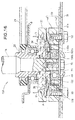
- Fig. 1 is a side view of the walk-behind lawn mower 10 equipped with a first embodiment of the blade mounting structure 20.
- a first embodiment of the walk-behind lawn mower 10 includes: a downwardly-opening housing 11; front and rear wheels 12 and 13 provided on the housing 11; an operating handle 14 provided on a rear portion of the housing 11; an engine (power source) 15 provided over the housing 11; an output shaft 16 extending downward from the engine 15; and the blade mounting structure 20 mounted on the output shaft 16.
- a pulley 22 is press-fitted on the output shaft 16 and connected to the output shaft 16 by a key (not shown), and a drive belt 24 is mounted or wound on the pulley 22 and a reduction gear mechanism 23.
- rotation of the output shaft 16 is transmitted to the reduction gear mechanism 23 via the pulley 22 and the drive belt 24.
- the walk-behind lawn mower 10 is self-propelled to travel (i.e., self-travel).
- the rotation of the output shaft 16 is transmitted to the blade mounting structure 20, so that a grass cutting blade 31 rotates. In this manner, the walk-behind lawn mower 10 can cut or clip grass by means of the grass cutting blade 31 while self-traveling.
- the first embodiment of the blade mounting structure 20 includes: a drive hub 26 mounted on the output shaft 16; a friction member 27 disposed around the drive hub 26; a blade holder 28 disposed beneath the friction member 27; a coned disk spring 29 disposed between the blade holder 28 and the friction member 27; the grass cutting blade 31 attached to the blade holder 28; and an energy absorbing member 32 disposed between the blade holder 28 and the drive hub 26.
- the drive hub 26 is disposed beneath the pulley 22 and press-fitted on the output shaft 16 from below, and the drive hub 26 is connected to the output shaft 16 via a key (not shown). Thus, the rotation of the output shaft 16 is transmitted to the drive hub 26 so that the hub 26 rotates together with the output shaft 16.
- the drive hub 26 press-fitted on the output shaft 26 protrudes radially outward beyond the output shaft 16, and thus, the drive hub 26 lies in a disk shape around the output shaft 16.
- the drive hub 26 has a protruding section (hereinafter “hub's protruding section”) 35 protruding downward from the bottom surface 26a, and a curved surface (hub's curved surface) 36 along its outer periphery.
- the hub's curved surface 36 is a frictional surface defined by a part of a convex spherical surface; more specifically, the hub's curved surface 36 is formed as a convexly arcuately curved surface that gradually gets away from the output shaft 16 in a direction from its lower end 36a to its upper end 36b.
- the friction member 27 is disposed around the drive hub 26 (see also Fig. 2 ) and has a frictional curved surface 38 along its inner periphery.
- the frictional curved surface 38 is a frictional defined by a part of a concave spherical surface; more specifically, the frictional curved surface 38 is formed as a concave curved surface that is complementary in shape to the hub's curved surface 36 and that confronts and extends along the hub's curved surface 36.
- the hub's curved surface 36 of the drive hub 26 and the frictional curved surface 38 of the friction member 27 are formed to be capable of abuttingly engage with (contact) each other over their entire regions.
- frictional force is produced between the hub's curved surface 36 and the frictional curved surface 38, so that driving force of the drive hub 26 can be transmitted to the friction member 27.
- the friction member 27 can be rotated together with the drive hub 26.
- the frictional curved surface 38 and the hub's curved surface 36 are slidable on each other in given directions in the mutually-abutting state.
- the friction member 27 can be not only rotated relative to the drive hub 26 in a horizontal direction (i.e., direction of arrow A) but also moved relative to the drive hub 26 in a vertical (up-down) direction (i.e., direction of arrow B).
- the blade holder 28 is disposed beneath the friction member 27 and fitted over a lower portion 16a of the output shaft 16 with an interval D1 left therebetween.
- the blade holder 28 includes a holder body 41 connected to the friction member 27, and a holder plate 47 disposed on the lower surface 41a of the holder body 41.
- the holder body 41 includes: a connection section 42 connecting to the friction member 27 so that it can rotate together with the friction member 27; a central fitting section 43 provided coaxially with the output shaft 16; a protruding section (holder's protruding section) 44 protruding inward from the upper end of the central fitting section 43; and a plurality of screw holes 45 provided around the central fitting section 43.
- the central fitting section 43 opens in a circular shape, and the holder's protruding section 44 is formed in a flange shape on the upper end of the fitting section 43.
- the holder plate 47 has a central opening 48 formed coaxially with the fitting section 43, an opening peripheral edge portion 49 defining the peripheral edge of the central opening 48, and a plurality of through-holes 51 formed around the opening peripheral edge portion 49.
- a coned disk spring 29 is disposed between the blade holder 28 and the friction member 27.
- the coned disk spring 29, which has an annular shape, has an inner peripheral portion 29a abutted against an upper stepped portion 41b of the holder body 41, and an outer peripheral portion 29b abutted against the underside 27a of the friction member 27.
- the friction member 27 is normally urged upward by biasing force of the coned disk spring 29 so that the frictional curved surface 38 is held abutted against the hub's curved surface 36.
- driving force of the engine 15 ( Fig. 1 ) is transmitted to the blade holder 28 via the drive hub 26 and the friction member 27.
- the conventionally-known lawn mowers are ones equipped with a blade brake clutch mechanism.
- a blade brake clutch mechanism With such a blade brake clutch mechanism, the above-mentioned frictional curved surface 38 can be spaced downward from the above-mentioned hub's curved surface 36 against the biasing force of the coned disk spring 29. Thus, the rotation of the grass cutting blade 31 can be stopped by the brake while the output shaft 16 is rotating.
- the walk-behind lawn mower 10 equipped with the first embodiment of the blade mounting structure 20 of the invention does not include such a blade brake clutch mechanism.
- the frictional curved surface 38 is normally held in abutting engagement with the hub's curved surface 36 by the biasing force of the coned disk spring 29.
- the grass cutting blade 31 is normally held rotatable together with the output shaft 16.
- the grass cutting blade 31 is attached to the blade holder 28 by means of a plurality of bolts 53.
- the grass cutting blade 31 has a central opening portion (blade's opening portion) 54 formed therethrough coaxially with the opening portion 48 of the holder plate 47, and a plurality of mounting holes 55 formed therethrough around the blade's opening portion 54.
- a plurality of bolts 53 are each inserted through a respective one of the mounting holes 55 of the grass cutting blade 31 and a respective one of the through-holes 51 of the holder plate 47 and screwed into a respective one of the screw holes 45 of the holder body 41.
- the grass cutting blade 31 is attached to a lower end portion of the holder body 41 by means of the plurality of bolts 53 via the holder plate 47.
- the opening peripheral edge portion 49 of the holder plate 47 protrudes inward of the central fitting section 43 of the holder body 41.
- annular space 57 is formed between the opening peripheral edge portion 49 of the holder plate 47 and the hub's protruding section 35 and between the lower portion 16a of the output shaft 16 and the fitting section 43 of the holder body 41.
- the hub's protruding section 35 and lower portion 16a of the output shaft 16 constitute members 52 peripheral to the blade holder 28.
- an inner collar 61 is press-fitted on the lower portion 16a of the output shaft 16, and an outer collar 63 is press-fitted in the fitting section 43.
- the inner collar 61 which has a cylindrical shape, includes a flange (inner flange) 62 projecting outward from its lower end portion, and the inner flange 62 is held in abutting engagement with a washer 73 and the opening peripheral edge portion 49.
- the washer 73 is disposed inward of and coaxially with the opening peripheral edge portion 49.
- the outer collar 63 which also has a cylindrical shape, includes a flange (outer flange) 64 projecting inward from its upper end portion, and the outer flange 64 is held in abutting engagement with the protruding section 44 of the holder body 41.
- the annular energy absorbing member 32 is disposed between the inner flange 62 and the outer flange 64. In other words, the annular energy absorbing member 32 is disposed between the opening peripheral edge portion 49 of the holder plate 47 and the protruding section 35 of the drive hub 26.
- the energy absorbing member 32 is a rubber member that is formed in an annular shape with the inner peripheral surface 66, outer peripheral surface 67, upper surface 68 and lower surface 69, and that has a substantially rectangular sectional shape.
- the energy absorbing member 32 thus formed in an annular shape can be suitably disposed in the annular space 57 (see Fig. 3 ).
- the energy absorbing member 32 can be readily assembled between the inner collar 61 and the outer collar 63 in the space 57.
- the energy absorbing member 32 is formed of rubber such that it maintains its shape, against deformation, during normal grass cutting operation (normal operating condition) by the cutting blade 31 ( Fig. 2 ) but deforms when a load (impact load) exceeding a predetermined value has acted on the energy absorbing member 32.
- the outer collar 63 is press-fitted from below in the fitting section 43 of the holder body 41, so that the outer flange 64 is abutted against the holder's protruding section 44.
- the outer flange 64 is held positioned vertically relative to the holder body 41.
- the inner collar 61 is, on the other hand, press-fitted from below on the lower portion 16a of the output shaft 16, and a bolt 72 is screwed into a screw hole 71 of the output shaft 16.
- the inner flange 62 is pressed from below by the washer 73 so that it is held positioned vertically relative to the output shaft 16.
- the upper surface 68 of the energy absorbing member 32 is abutted against the outer flange 64, while the lower surface 69 of the energy absorbing member 32 is abutted against the inner flange 62. Further, the opening peripheral edge portion 49 of the holder plate 47 is abutted against the inner flange 62. Because the energy absorbing member 32 is constructed to maintain its shape, against deformation, during normal operating condition, the holder body 41 is held positioned vertically by means of the outer flange 64, the energy absorbing member 32, the inner flange 62 and the opening peripheral edge portion 49.
- the grass cutting blade 31 By being attached to the lower surface 41a by the plurality of bolts 53 via the holder plate 47, the grass cutting blade 31 is held positioned vertically and centered accurately relative to the output shaft 16.
- operation for centering the grass cutting blade 31 can be performed with ease without taking much time and labor.
- the energy absorbing member 32 deforms, so that the impact load can be absorbed by the frictional curved surface 38 being slid relative to the hub's curved surface 36 in the direction of arrow A and in the direction of arrow B.
- the energy absorbing member 32 is positioned around the entire periphery of the lower portion 16a of the output shaft 16.
- the energy absorbing member 32 can be deformed suitably by the input impact load.
- the impact load input from the certain position along the periphery of the output shaft 16 can be absorbed suitably by the friction member 27 being moved vertically (in the direction of arrow B of Fig. 2 ) relative to the drive hub 26.
- the driving force of the engine 15 ( Fig. 1 ) is transmitted via the output shaft 16 to the drive hub 26. Then, the driving force is transmitted from the drive hub 26 to the friction member 27 by friction force produced between the hub's curved surface 36 and the frictional curved surface 38 of the friction member 27. Thus, the driving force is transmitted via the friction member 27 to the blade holder 28, so that the grass cutting blade 31 is rotated in a direction of arrow C together with the blade holder 28.
- the energy absorbing member 32 maintains its shape against deformation, and the energy absorbing member 32 rotates together with the blade holder 28 and the output shaft 16.
- the walk-behind lawn mower 10 cuts or clips grass while being propelled to travel (self-traveling).
- the grass cutting blade 31 can hit an obstacle, such as a sprinkler (not shown). Once the grass cutting blade 31 hits an obstacle, an impact load is input which would rotate the frictional curved surface 38 in a horizontal direction (direction of arrow D) relative to the hub's curved surface 36.
- an obstacle such as a sprinkler (not shown).
- the impact load produced by the grass cutting blade 31 hitting the obstacle is transmitted to the grass cutting blade 31 and the blade holder 28, and a load exceeding a predetermined value acts on the energy absorbing member 32. If such a load exceeding the predetermined value has acted on the energy absorbing member 32, the energy absorbing member 32 can deform. By the deformation of the energy absorbing member 32, the frictional curved surface 38 is slid relative to the hub's curved surface 36 as indicated by arrow D. By the sliding movement as indicated by arrow D, the impact load is converted into heat energy and absorbed, so that the output shaft 16 can be protected from the impact load.
- an impact load is also input which would move the friction member 27 relative to the drive hub 26 in a vertical direction (direction of arrow E), as shown in Fig. 6 .
- the input impact load is transmitted to the grass cutting blade 31 and the blade holder 28, so that a load exceeding a predetermined value acts on the energy absorbing member 32.
- the load exceeding the predetermined value acting on the energy absorbing member 32 can deform the energy absorbing member 32.
- the frictional curved surface 38 is slid relative to the hub's curved surface 36 as indicated by arrow E.
- the impact load is converted into heat energy and absorbed, so that the output shaft 16 can be protected from the impact load.
- the second embodiment of the blade mounting structure 80 will be described with reference to Figs. 7 and 8 .
- the second embodiment of the blade mounting structure 80 is characterized in that the energy absorbing member 32 in the first embodiment of the blade mounting structure 20 is replaced with an energy absorbing member 82 and that the outer collar 63 in the first embodiment is omitted; the other structural features of the second embodiment are substantially similar to those of the first embodiment of the blade mounting structure 20.
- the energy absorbing member 82 is a member formed of soft steel or resin and has a substantially bellows-like (Z) sectional shape defined with an upper portion 83, a lower portion 84 and a slanting portion 85.
- the upper portion 83 and the lower portion 84 are formed to extend horizontally.
- the energy absorbing member 82 in the second embodiment has an annular shape like the energy absorbing member 32 in the first embodiment, so that the energy absorbing member 82 is disposed suitably in the annular space 57.
- the energy absorbing member 82 can be readily assembled into the space 57.
- the energy absorbing member 82 is formed of soft steel or resin such that it maintains its shape, against deformation, during the normal grass cutting operation by the cutting blade 31 ( Fig. 7 ) but deforms when a load (impact load) exceeding a predetermined value has acted on the energy absorbing member 82.
- a load impact load
- the energy absorbing member 82 is formed of soft steel or resin such that it maintains its shape, against deformation, during the normal grass cutting operation by the cutting blade 31 ( Fig. 7 ) but deforms when a load (impact load) exceeding a predetermined value has acted on the energy absorbing member 82.
- the upper portion 83 of the energy absorbing member 82 is abutted from below against the holder's protruding section 44. Further, the inner flange 62 of the inner collar 61 is held positioned vertically (in the up-down direction) relative to the output shaft 16.
- the holder body 41 is held positioned vertically by means of the energy absorbing member 82, the inner flange 62 and the opening peripheral edge portion 49.
- the grass cutting blade 31 By being attached to the lower surface 41a of the holder body 41 via the holder plate 47, the grass cutting blade 31 is held positioned vertically and centered accurately relative to the output shaft 16. Thus, in assembling the grass cutting blade 31, the operation for centering the grass cutting blade 31 can be performed with ease without taking much time and labor.
- the energy absorbing member 82 maintains its shape against deformation, and the energy absorbing member 82 rotates together with the blade holder 28 and the output shaft 16, so that the grass cutting blade 31 can cut grass in an appropriate manner.
- the energy absorbing member 32 deforms, so that the load can be absorbed by the frictional curved surface 38 being slid relative to the hub's curved surface 36 in the direction of arrow A and in the direction of arrow B.
- the energy absorbing member 82 is positioned around the entire periphery of the lower portion 16a of the output shaft 16.
- the energy absorbing member 82 can be deformed suitably by the input impact load.
- the impact load input from the certain position along the periphery of the output shaft 16 can be absorbed suitably by the friction member 27 being moved vertically (in the direction of arrow B of Fig. 2 ) relative to the drive hub 26.
- the second embodiment of the blade mounting structure 80 constructed in the aforementioned manner can achieve the same advantageous benefits as the first embodiment of the blade mounting structure 20.
- the second embodiment of the blade mounting structure 80 can omit or dispense with the outer collar 63 by abutting the upper portion 83 of the energy absorbing member 82 against the holder's protruding section 44. In this way, it is possible to reduce the number of component parts of the blade mounting structure 80 and facilitate the operation for assembling the blade mounting structure 80.
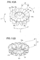
- the third embodiment of the blade mounting structure 90 is characterized in that the energy absorbing member 32 in the first embodiment of the blade mounting structure 20 is replaced with an energy absorbing member 92 and that the outer collar 63 in the first embodiment is omitted; the other structural features of the third embodiment are substantially similar to those of the first embodiment of the blade mounting structure 20.
- the energy absorbing member 92 is an annular member formed of soft steel or resin and has a peripheral side wall section 93 of an annular shape, and an annular upper plate 95 provided on an upper end portion 93a of the peripheral side wall section 93.
- the third embodiment of the blade mounting structure 90 will be described in relation to a case where the energy absorbing member 92 is formed of resin.
- the peripheral side wall section 93 is bent at a plurality of positions thereof in such a manner that it projects from an imaginary circle of a small diameter D1 to an imaginary circle of a large diameter D2 with respect to a circumferential direction to thereby form a convex-concave shape (bellows-like shape).
- the annular upper plate 95 is formed in such an annular shape as to be capable of being provided on the upper end portion 93a of the peripheral side wall section 93 and in a convex-concave shape (bellows-like shape) with respect to the vertical (up-down) direction. More specifically, the upper plate 95 has a plurality of upwardly bent portions (upward projecting portions) 95a each slanting downward from an outer peripheral edge portion 95b to an inner peripheral edge portion 95c.
- the energy absorbing member 92 is formed in an annular shape with the peripheral side wall section 93 and the upper plate 95.
- the energy absorbing member 92 thus formed in an annular shape can be suitably disposed in the annular space 57 (see Fig. 9 ).
- the energy absorbing member 92 can be readily assembled into the space 57.
- the energy absorbing member 92 is formed of soft steel or resin such that it maintains its shape, against deformation, during the normal grass cutting operation by the cutting blade 31 ( Fig. 9 ) but deforms when a load (impact load) exceeding a predetermined value has acted on the energy absorbing member 92.
- the peripheral side wall section 93 of the energy absorbing member 92 is formed in a convex-concave shape (bellows-like shape) with respect to the circumferential direction
- the upper plate 95 is formed in a convex-concave shape (bellows-like shape) with respect to the vertical direction.
- the plurality of the outer peripheral edge portions 95b (see Fig. 10 ) of the upper plate 95 of the energy absorbing member 92 are abutted from below against the holder's protruding section 44. Further, the inner flange 62 of the inner collar 61 is held positioned vertically (in the up-down direction) relative to the output shaft 16.
- the energy absorbing member 92 maintains its shape, against deformation, during the normal operating condition, and thus, the holder body 41 is held positioned vertically by means of the energy absorbing member 92, the inner flange 62 and the opening peripheral edge portion 49.
- the grass cutting blade 31 By being attached to the lower surface 41a of the holder body 41 via the holder plate 47, the grass cutting blade 31 is held positioned vertically and centered accurately relative to the output shaft 16. Thus, in assembling the grass cutting blade 31, the operation for centering the grass cutting blade 31 can be performed with ease without taking much time and labor.
- the energy absorbing member 92 maintains its shape against deformation, the energy absorbing member 92 rotates together with the blade holder 28 and the output shaft 16, so that the grass cutting blade 31 can cut grass in an appropriate manner.
- the energy absorbing member 92 deforms, so that the load can be absorbed by the frictional curved surface 38 being slid relative to the hub's curved surface 36 in the direction of arrow A and in the direction of arrow B.
- the energy absorbing member 92 is positioned around the entire periphery of the lower portion 16a of the output shaft 16.
- the energy absorbing member 92 can be deformed suitably by the input impact load.
- the impact load input from the certain position along the periphery of the output shaft 16 can be absorbed suitably by the friction member 27 being moved vertically (in the direction of arrow B in Fig. 9 ) relative to the drive hub 26.
- the third embodiment of the blade mounting structure 90 constructed in the aforementioned manner can achieve the same advantageous benefits as the first embodiment of the blade mounting structure 20. Further, the third embodiment of the blade mounting structure 90 can omit or dispense with the outer collar 63 by abutting the outer peripheral edge portions 95b of the energy absorbing member 92 (upper plate) against the holder's protruding section 44. In this way, it is possible to reduce the number of component parts of the blade mounting structure 90 and facilitate the operation for assembling the blade mounting structure 90.
- each of the upward bent potions 95a of the upper plate 95 is formed to slant downward from the outer peripheral edge portion 95b to the inner peripheral edge portion 95c
- the present invention is not so limited, and each of the upward bent potions 95a of the upper plate 95 may be formed to extend horizontally from the outer peripheral edge portion 95b to the inner peripheral edge portion 95c. Even with the upward bent potions 95a extending horizontally like this, the same advantageous benefits as the above-described third embodiment can be achieved.
- the fourth embodiment of the blade mounting structure 100 is characterized in that the energy absorbing member 32 in the first embodiment of the blade mounting structure 20 is replaced with an energy absorbing member 102 and that a bearing 103 is provided between the energy absorbing member 102 and the output shaft 16; the other structural features of the fourth embodiment are substantially similar to those of the first embodiment of the blade mounting structure 20.
- the bearing 103 is a ball bearing whose inner ring 105 is press-fitted from below on the lower portion 16a of the output shaft 16. In this condition, the upper surface 105a of the inner ring 105 is abutted against the hub's protruding section 35, while the lower surface 105b of the inner ring 105 is abutted against the washer 73. Thus, the bearing 103 is held positioned in the space 57.
- the bearing 103 provided on the lower portion 16a of the output shaft 16, allows the rotation of the grass cutting blade 31 to be stopped with the rotation of the output shaft 16 still maintained.
- the walk-behind lawn mower equipped with the fourth embodiment of the blade mounting structure 100 is constructed to include a blade brake clutch mechanism.
- a blade brake clutch mechanism With such a blade brake clutch mechanism, the frictional curved surface 38 can be spaced downward from the hub's curved surface 36 against the biasing force of the coned disk spring 29.
- the rotation of the grass cutting blade 31 can be stopped by the brake with the rotation of the output shaft 16 still maintained.
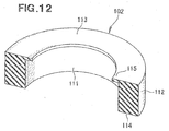
- the energy absorbing member 102 is a rubber member that is formed in an annular shape and in a substantially rectangular sectional shape defined with the inner peripheral surface 111, outer peripheral surface 112, upper surface 113 and lower surface 114.
- the energy absorbing member 102 also has an upper flange 115 projecting inward from an intersection between the inner peripheral surface 111 and the upper surface 113.
- the energy absorbing member 102 thus formed in an annular shape can be suitably disposed in the annular space 57.
- the energy absorbing member 102 can be readily assembled to between the outer ring 106 and the fitting section 43. Further, by forming the energy absorbing member 102 in an annular shape and in a simple substantially rectangular sectional shape as noted above, it is possible to reduce manufacturing cost of the energy absorbing member 102.
- the energy absorbing member 102 is formed of rubber such that it maintains its shape, against deformation, during the normal grass cutting operation by the cutting blade 31 (see Fig. 11 ) but deforms when a load exceeding a predetermined value has acted on the energy absorbing member 102.
- the upper surface 113 and the upper flange 115 of the energy absorbing member 102 are abutted from below against the holder's protruding section 44, and the upper flange 115 is abutted from above against the upper surface 106a of the outer ring 106.
- the upper flange 115 is disposed between the holder's protruding section 44 and the upper surface 106a of the outer ring 106, and the holder's protruding section 44 is spaced upward from the upper surface 106a of the outer ring 106.
- the opening peripheral edge portion 49 of the holder plate 47 is abutted from below against the lower surface 114 of the energy absorbing member 102 but also abutted from below against the lower surface 106b of the outer ring 106.
- the holder body 41 is held positioned in the vertical direction by the bearing 103, the energy absorbing member 102 and the opening peripheral edge portion 49.
- the grass cutting blade 31 is held positioned vertically and centered accurately relative to the output shaft 16.
- the operation for centering the grass cutting blade 31 can be performed with ease without taking much time and labor.
- the energy absorbing member 102 maintains its shape against deformation during the normal grass cutting operation by the cutting blade 31, the energy absorbing member 102 rotates together with the blade holder 28 and the output shaft 16, so that the grass cutting blade 31 can cut grass in an appropriate manner.
- the lawn mower 10 cuts grass by rotating the grass cutting blade 31 as indicated by arrow H in Fig. 13A .
- the grass cutting blade 31 can hit an obstacle, such as a sprinkler.
- an impact load is input which would rotate the frictional curved surface 38 in a horizontal direction (direction of arrow I in Fig. 13A ) relative to the hub's curved surface 36.
- Such an input impact load is transmitted to the grass cutting blade 31 and the blade holder 28, so that a load exceeding a predetermined value acts on the energy absorbing member 102.
- the load exceeding the predetermined value acting on the energy absorbing member 102 can deform the energy absorbing member 102.
- the frictional curved surface 38 is slid relative to the hub's curved surface 36 as indicated by arrow 1.
- the impact load is converted into heat energy and absorbed, so that the output shaft 16 can be protected from the impact load.
- the frictional curved surface 38 can be slid relative to the hub's curved surface 36 as indicated by arrow J in Fig. 13B .
- the impact load is converted into heat energy and absorbed, so that the output shaft 16 can be protected from the impact load.
- the energy absorbing member 102 is positioned around the entire periphery of the lower portion 16a of the output shaft 16.
- the energy absorbing member 102 can be deformed suitably by the input impact load.
- the fourth embodiment of the blade mounting structure 100 can suitably absorb the impact load input from the certain position along the periphery of the lower portion 16a of the output shaft 16, by moving the friction member 27 relative to the drive hub 26 in the vertical direction (direction of arrow B in Fig. 11 ).
- the fourth embodiment of the blade mounting structure 100 constructed in the aforementioned manner can achieve the same advantageous benefits as the first embodiment of the blade mounting structure 20.
- the fifth embodiment of the blade mounting structure 120 is characterized in that the energy absorbing member 102 in the fourth embodiment of the blade mounting structure 100 is replaced with an energy absorbing member 122; the other structural features of the fifth embodiment are substantially similar to those of the fourth embodiment of the blade mounting structure 100.
- the energy absorbing member 122 which is an annular member formed of soft steel or resin, has a substantially bellows-like sectional shape defined with a slanting upper section 123, a slanting lower section 124 and a plurality of connecting sections 125 formed by an intermediate portion, located between the upper and lower sections 123 and 124, being bent a plurality of times.
- the energy absorbing member 122 further has a flat upper flange 126 projecting flat inward from the inner peripheral edge 123a of the upper section 123, and an outer peripheral portion 127 of the lower section 124 extends flat.
- the energy absorbing member 122 can be suitably disposed in the annular space 57 (see Fig. 14 ). Also, by being formed in an annular shape in accordance with the annular shape of the space 57 as noted above, the energy absorbing member 122 can be readily assembled into the space 57.
- the energy absorbing member 122 is formed of soft steel or resin such that it maintains its shape, against deformation, during the normal grass cutting operation by the cutting blade 31 (see Fig. 14 ) but deforms when a load (impact load) exceeding a predetermined value has acted on the energy absorbing member 122.
- a load impact load
- the energy absorbing member 122 is formed of soft steel or resin such that it maintains its shape, against deformation, during the normal grass cutting operation by the cutting blade 31 (see Fig. 14 ) but deforms when a load (impact load) exceeding a predetermined value has acted on the energy absorbing member 122.
- the upper flange 126 of the energy absorbing member 122 is abutted from below against the holder's protruding section 44. Further, the upper flange 126 is abutted from above against the upper surface 106a of the outer ring 106. Namely, the upper flange 126 is disposed between the holder's protruding section 44 and the upper surface 106a of the outer ring 106 so that the holder's protruding section 44 is spaced upward from the upper surface 106a of the outer ring 106.
- the opening peripheral edge portion 49 of the holder plate 47 is abutted from below against the outer peripheral portion 127 of the energy absorbing member 122 but also abutted from below against the lower surface 106b of the outer ring 106.
- the holder body 41 is held positioned in the vertical direction by the bearing 103, the energy absorbing member 122 and the opening peripheral edge portion 49.
- the grass cutting blade 31 is held positioned vertically and centered accurately relative to the output shaft 16.
- the operation for centering the grass cutting blade 31 can be performed with ease without taking much time and labor.
- the energy absorbing member 122 maintains its shape, against deformation, during the normal grass cutting operation by the cutting blade 31, the energy absorbing member 122 rotates together with the blade holder 28 and the output shaft 16, so that the grass cutting blade 31 can cut grass in an appropriate manner.
- the energy absorbing member 122 deforms, so that the load can be absorbed by the frictional curved surface 38 being slid relative to the hub's curved surface 36 in the direction of arrow A and in the direction of arrow B.
- the frictional curved surface 38 can be slid relative to the hub's curved surface 36 in the direction of arrow B in Fig. 14 .
- the energy absorbing member 122 is positioned around the entire periphery of the lower portion 16a of the output shaft 16.
- the energy absorbing member 122 can be deformed suitably by the input impact load.
- the fifth embodiment of the blade mounting structure 120 can suitably absorb the impact load input from the certain position along the periphery of the lower portion 16a of the output shaft 16, by moving the friction member 27 relative to the drive hub 26 in the vertical direction (direction of arrow B in Fig. 14 ).
- the fifth embodiment of the blade mounting structure 120 constructed in the aforementioned manner can achieve the same advantageous benefits as the fourth embodiment of the blade mounting structure 100.
- the sixth embodiment of the blade mounting structure 130 is characterized in that the energy absorbing member 102 in the fourth embodiment of the blade mounting structure 100 is replaced with an energy absorbing member 132; the other structural features of the sixth embodiment are substantially similar to those of the fourth embodiment of the blade mounting structure 100.
- the energy absorbing member 132 which is an annular member formed of soft steel or resin, has an annular peripheral side wall section 133, and an annular upper plate 135 provided on an upper end portion 133a of the peripheral side wall section 133.
- the sixth embodiment of the blade mounting structure 130 will be described in relation to a case where the energy absorbing member 132 is formed of resin.
- the peripheral side wall section 133 is bent at a plurality of positions thereof in such a manner that it projects from an imaginary circle of a small diameter D3 to an imaginary circle of a large diameter D4 to thereby form a convex-concave shape (bellows-like shape) with respect to a circumferential direction of the peripheral side wall section 133.
- the annular upper plate 135 is formed in such an annular shape as to be capable of being provided on the upper end portion 133a of the peripheral side wall section 133 and in a convex-concave shape (bellows-like shape) with respect to the vertical (up-down) direction, and the upper plate 135 has an upper flange 136 formed in an annular shape on and along the inner periphery thereof. More specifically, the upper plate 135 has a plurality of upwardly bent portions 135a each slanting downward from an outer peripheral edge portion 135b to an inner peripheral edge portion 135c. The outer peripheral edge portion 135b is located at generally the same height as the upper surface of the upper flange 136.
- the energy absorbing member 132 is formed in an annular shape with the peripheral side wall section 133 and the upper plate 95.
- the energy absorbing member 132 thus formed in an annular shape can be suitably disposed in the annular space 57.
- the energy absorbing member 132 can be readily assembled into the space 57.
- the energy absorbing member 132 maintains its shape, against deformation, during the normal grass cutting operation by the cutting blade 31 (see Fig. 16 ) but deforms when a load (impact load) exceeding a predetermined value has acted on the energy absorbing member 132.
- the peripheral side wall section 133 of the energy absorbing member 132 is formed in a convex-concave shape (bellows-like shape) with respect to the circumferential direction
- the upper plate 135 is formed in a convex-concave shape (bellows-like shape) with respect to the vertical direction.
- the outer peripheral edge portion 135b of the upper plate 135 of the energy absorbing member 102 is abutted from below against the holder's protruding section 44, and the upper flange 136 of the upper plate 135 is abutted from above the upper surface 106a of the outer ring 106.
- the upper flange 136 is disposed between the holder's protruding section 44 and the upper surface 106a of the outer ring 106, and the holder's protruding section 44 is spaced upward from the upper surface 106a of the outer ring 106.
- the opening peripheral edge portion 49 of the holder plate 47 is abutted from below against a lower end portion 133b of the energy absorbing member 132 (peripheral side wall section 133) but also abutted from below against the lower surface 106b of the outer ring 106.
- the energy absorbing member 132 maintains its shape, against deformation, during the normal condition, so that the holder body 41 is held positioned in the vertical direction by the bearing 103, the energy absorbing member 132 and the opening peripheral edge portion 49.
- the grass cutting blade 31 is held positioned vertically and centered accurately relative to the output shaft 16.
- the operation for centering the grass cutting blade 31 can be performed with ease without taking much time and labor.
- the energy absorbing member 132 maintains its shape against deformation, and the energy absorbing member 132 rotates together with the blade holder 28 and the output shaft 16, so that the grass cutting blade 31 can cut grass in an appropriate manner.
- the energy absorbing member 132 deforms, so that the load can be absorbed by the frictional curved surface 38 being slid relative to the hub's curved surface 36 in the direction of arrow A and in the direction of arrow B.
- the frictional curved surface 38 can be suitably slid relative to the hub's curved surface 36 in the direction of arrow B in Fig. 14 .
- the energy absorbing member 132 is positioned around the entire periphery of the lower portion 16a of the output shaft 16.
- the energy absorbing member 132 can be deformed suitably by the input impact load.
- the sixth embodiment of the blade mounting structure 130 can suitably absorb the impact load input from the certain position along the periphery of the lower portion 16a of the output shaft 16, by moving the friction member 27 relative to the drive hub 26 in the vertical direction (direction of arrow B in Fig. 16 ).
- the sixth embodiment of the blade mounting structure 130 constructed in the aforementioned manner can achieve the same advantageous benefits as the fourth embodiment of the blade mounting structure 100.
- each of the upward bent potions 135a of the upper plate 135 is formed to slant downward from the outer peripheral edge portion 135b to the inner peripheral edge portion 135c
- the present invention is not so limited, and each of the upward bent potions 135a of the upper plate 135 may be formed to extend horizontally from the outer peripheral edge portion 135b to the inner peripheral edge portion 135c. Even with the upward bent potions 135a extending horizontally like this, the same advantageous benefits as the above-described sixth embodiment can be achieved.
- the blade mounting structure of the lawn mower of the present invention is not limited to the above-described embodiments and may be modified variously.
- the first to sixth embodiments have been described above as applied to the walk-behind lawn mower 10, they may be applied to other types of lawn mowers, such as a riding type lawn mower which a human operator rides on.
- the present invention is not so limited, and any other type of power source, such as an electrically-driven device, may be employed as the power source.
- the shapes and constructions of the walk-behind lawn mower, engine, output shaft, blade mounting structure, drive hub, friction member, blade holder, grass cutting blade, energy absorbing member, hub's curved surface, frictional curved surface, peripheral members, etc. are not limited to those shown and described above and may be modified as necessary.
- the basic principles of the present invention are well suited for application to lawn mowers equipped with a blade mounting structure where a blade holder is mounted on an output shaft of a power source and a grass cutting blade is attached to the blade holder.
Landscapes
- Life Sciences & Earth Sciences (AREA)
- Environmental Sciences (AREA)
- Harvester Elements (AREA)
Description
- The present invention relates to a blade mounting structure of a lawn mower where a grass cutting blade is mounted on an output shaft of a power source via a blade holder.
- A blade mounting structure of a lawn mower according to the preamble of claim 1 is known from
JP H06-17839 A - By the friction member being pressed via a coned disk spring, the frictional surface of the friction member is brought into contact with the frictional surface of the drive hub, so that driving force of the power source is transmitted to the grass cutting blade via the output shaft, the drive hub, the friction member and the blade holder. Thus, the grass cutting blade can be rotated to cut grass.
- If the grass cutting blade hits an obstacle, such as a sprinkler or stone, during grass cutting operation, the frictional surface of the friction member can slide relative to the frictional surface of the drive hub and thereby absorb an impact load input to the grass cutting blade. Thus, it is possible to suppress the input impact load from being transmitted to the output shaft and thereby protect the output shaft.
- However, in the lawn mower disclosed in the relevant patent literature, where the frictional surface of the drive hub is formed in a convex truncated cone shape while the frictional surface of the friction member is formed in a concave truncated cone shape, the frictional surface of the friction member cannot be slid relative to the frictional surface of the drive hub in a vertical (up-down) direction. Thus, when the grass cutting blade hits an obstacle, such as a sprinkler or stone, so that an impact load that acts on the friction member is input in such a manner as to move the friction member in the vertical direction, a bending load acts on the output shaft.
- As a measure to let go the bending load acting on the output shaft, the friction member may be constructed so as to be able to slide relative to the drive hub in the vertical direction. However, if such a measure is employed, it would become difficult to position the friction member and the blade holder, and thus, it would take much time and labor to center the grass cutting blade relative to the output shaft.
- In view of the foregoing prior art problems, it is an object of the present invention to provide an improved blade mounting structure of a lawn mower which can effectively absorb an impact load by permitting movement of the friction member in horizontal and vertical directions but also allows the grass cutting blade to be centered relative to the output shaft with ease.
- In order to accomplish the above-mentioned object, the present invention provides an improved blade mounting structure of a lawn mower, which comprises: a drive hub mounted on an output shaft of a power source and protruding radially outward beyond the outer periphery of the output shaft; a friction member disposed around the drive hub and configured to transmit driving force from the drive hub to a blade holder when the friction member is in abutting engagement with the drive hub, the drive hub and the friction member having respective curved surfaces slidable on each other when the drive hub and the friction member are in abutting engagement with each other; a grass cutting blade attached to the blade holder; and an energy absorbing member disposed in a space defined by the blade holder and members peripheral to the blade holder, the energy absorbing member being constructed to maintain its shape during normal operating condition but deform when a load exceeding a predetermined value acts on the energy absorbing member.
- In the present invention, the drive hub and the friction member have the respective curved surfaces that are of complementary curved shapes and that are slidable on each other when the drive hub and the friction member are in abutting engagement with each other. Thus, when the drive hub and the friction member are in abutting engagement with each other, the friction member can be rotated relative to the drive hub in a horizontal direction but also moved relative to the drive hub in a vertical (up-down) direction.
- Further, in the present invention, the energy absorbing member is disposed in the space defined by the blade holder and the members (in this case, the output shaft and the drive shaft) peripheral to the blade holder, and the energy absorbing member is constructed to deform when a load exceeding a predetermined value acts on the energy absorbing member in a vertical direction. Thus, when an impact load has been input which would move the friction member relative to the drive hub in the vertical direction, the present invention can absorb the impact load by deforming the energy absorbing member to cause the friction member to move in the vertical direction. Further, when an impact load has been input which would move the friction member relative to the drive hub in the horizontal direction, the present invention can absorb the impact load by causing the friction member to move relative to the drive in the horizontal direction.
- Furthermore, in the present invention, the energy absorbing member, disposed in the space defined by the blade holder and the members peripheral to the blade holder, is constructed to maintain its shape against deformation during the normal operating condition. Thus, the present invention can position the blade holder at an accurate position relative to the peripheral member by means of the energy absorbing member. Further, by the shape of the energy absorbing member being maintained against deformation, the present invention can position the blade holder (grass cutting blade) at the accurate position and thereby readily center the grass cutting blade relative to the output shaft.
- Preferably, the space is defined in an annular shape, about the output shaft, with the blade holder, the drive hub and the output shaft, and the energy absorbing member has an annular shape and disposed in the annular space. By being formed in the annular shape in accordance with the annular shape of the space, the energy absorbing member can be readily assembled into the space. Further, by being disposed in the annular space, the energy absorbing member can be positioned around the output shaft. Thus, when an impact load has been input from a certain position along the periphery of the output shaft, the energy absorbing member can be deformed suitably by the input impact load. In this way, the impact load input from the certain position along the periphery of the output shaft can be absorbed suitably by the friction member being moved vertically relative to the drive hub.
- The following will describe embodiments of the present invention, but it should be appreciated that the present invention is not limited to the described embodiments and various modifications of the invention are possible without departing from the basic principles. The scope of the present invention is therefore to be determined solely by the appended claims.
- Certain preferred embodiments of the present invention will hereinafter be described in detail, by way of example only, with reference to the accompanying drawings, in which:
-
Fig. 1 is a side view of a walk-behind lawn mower equipped with a first embodiment of a blade mounting structure of the present invention; -
Fig. 2 is a sectional view of the first embodiment of the blade mounting structure ofFig. 1 ; -
Fig. 3 is an enlarged sectional view of a section surrounded at 3 ofFig. 2 ; -
Fig. 4 is an exploded perspective view showing relationship among an energy absorbing member, an inner color and an outer collar ofFig. 3 ; -
Figs. 5A and 5B are views explanatory of an example manner in which a horizontal impact load is absorbed by the first embodiment of the blade mounting structure; -
Fig. 6 is a view explanatory of an example manner in which a vertical impact load is absorbed by the first embodiment of the blade mounting structure; -
Fig. 7 is a sectional view of a second embodiment of the blade mounting structure of the present invention; -
Fig. 8 is a perspective view of an energy absorbing member ofFig. 7 ; -
Fig. 9 is a sectional view of a third embodiment of the blade mounting structure of the present invention; -
Fig. 10A is an upper perspective view of an energy absorbing member shown inFig. 9 , andFig. 10B is a lower perspective view of the energy absorbing member shown inFig. 9 ; -
Fig. 11 is a sectional view of a fourth embodiment of the blade mounting structure of the present invention; -
Fig. 12 is a perspective view of an energy absorbing member shown inFig. 11 ; -
Figs. 13A and 13B are views explanatory of an example manner in which an impact load is absorbed by the fourth embodiment of the blade mounting structure; -
Fig. 14 is a sectional view of a fifth embodiment of the blade mounting structure of the present invention; -
Fig. 15 is a perspective view of an energy absorbing member shown inFig. 14 ; -
Fig. 16 is a sectional view of a sixth embodiment of the blade mounting structure of the present invention; and -
Fig. 17 is a perspective view of an energy absorbing member shown inFig. 16 . - Now, a description will be given about and preferred embodiments of a blade mounting structure of a lawn mower in relation to a case where the lawn mower is constructed as a walk-behind
lawn mower 10. -
Fig. 1 is a side view of the walk-behindlawn mower 10 equipped with a first embodiment of theblade mounting structure 20. As shown inFig. 1 , a first embodiment of the walk-behindlawn mower 10 includes: a downwardly-opening housing 11; front andrear wheels housing 11; anoperating handle 14 provided on a rear portion of thehousing 11; an engine (power source) 15 provided over thehousing 11; anoutput shaft 16 extending downward from theengine 15; and theblade mounting structure 20 mounted on theoutput shaft 16. - In the walk-behind
lawn mower 10, apulley 22 is press-fitted on theoutput shaft 16 and connected to theoutput shaft 16 by a key (not shown), and adrive belt 24 is mounted or wound on thepulley 22 and areduction gear mechanism 23. Thus, as theengine 15 is driven, rotation of theoutput shaft 16 is transmitted to thereduction gear mechanism 23 via thepulley 22 and thedrive belt 24. Then, by therear wheel 13 being rotated by thereduction gear mechanism 23, the walk-behindlawn mower 10 is self-propelled to travel (i.e., self-travel). Meanwhile, the rotation of theoutput shaft 16 is transmitted to theblade mounting structure 20, so that agrass cutting blade 31 rotates. In this manner, the walk-behindlawn mower 10 can cut or clip grass by means of thegrass cutting blade 31 while self-traveling. - As shown in
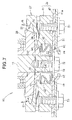
Fig. 2 , the first embodiment of theblade mounting structure 20 includes: adrive hub 26 mounted on theoutput shaft 16; afriction member 27 disposed around thedrive hub 26; ablade holder 28 disposed beneath thefriction member 27; a coneddisk spring 29 disposed between theblade holder 28 and thefriction member 27; thegrass cutting blade 31 attached to theblade holder 28; and anenergy absorbing member 32 disposed between theblade holder 28 and thedrive hub 26. - The
drive hub 26 is disposed beneath thepulley 22 and press-fitted on theoutput shaft 16 from below, and thedrive hub 26 is connected to theoutput shaft 16 via a key (not shown). Thus, the rotation of theoutput shaft 16 is transmitted to thedrive hub 26 so that thehub 26 rotates together with theoutput shaft 16. Thedrive hub 26 press-fitted on theoutput shaft 26 protrudes radially outward beyond theoutput shaft 16, and thus, thedrive hub 26 lies in a disk shape around theoutput shaft 16. - As shown in
Fig. 3 , thedrive hub 26 has a protruding section (hereinafter "hub's protruding section") 35 protruding downward from thebottom surface 26a, and a curved surface (hub's curved surface) 36 along its outer periphery. The hub'scurved surface 36 is a frictional surface defined by a part of a convex spherical surface; more specifically, the hub'scurved surface 36 is formed as a convexly arcuately curved surface that gradually gets away from theoutput shaft 16 in a direction from itslower end 36a to itsupper end 36b. - The
friction member 27 is disposed around the drive hub 26 (see alsoFig. 2 ) and has a frictionalcurved surface 38 along its inner periphery. The frictionalcurved surface 38 is a frictional defined by a part of a concave spherical surface; more specifically, the frictionalcurved surface 38 is formed as a concave curved surface that is complementary in shape to the hub'scurved surface 36 and that confronts and extends along the hub'scurved surface 36. - The hub's
curved surface 36 of thedrive hub 26 and the frictionalcurved surface 38 of thefriction member 27 are formed to be capable of abuttingly engage with (contact) each other over their entire regions. When the hub'scurved surface 36 and the frictionalcurved surface 38 are in abutting engagement with each other (i.e., in a mutually-abutting state), frictional force is produced between the hub'scurved surface 36 and the frictionalcurved surface 38, so that driving force of thedrive hub 26 can be transmitted to thefriction member 27. In other words, by the frictional force produced between the hub'scurved surface 36 and the frictionalcurved surface 38, thefriction member 27 can be rotated together with thedrive hub 26. - Referring back to
Fig. 2 , the frictionalcurved surface 38 and the hub'scurved surface 36 are slidable on each other in given directions in the mutually-abutting state. Thus, in the mutually-abutting state of the frictionalcurved surface 38 and the hub'scurved surface 36, thefriction member 27 can be not only rotated relative to thedrive hub 26 in a horizontal direction (i.e., direction of arrow A) but also moved relative to thedrive hub 26 in a vertical (up-down) direction (i.e., direction of arrow B). - The
blade holder 28 is disposed beneath thefriction member 27 and fitted over alower portion 16a of theoutput shaft 16 with an interval D1 left therebetween. Theblade holder 28 includes aholder body 41 connected to thefriction member 27, and aholder plate 47 disposed on thelower surface 41a of theholder body 41. - The
holder body 41 includes: aconnection section 42 connecting to thefriction member 27 so that it can rotate together with thefriction member 27; a centralfitting section 43 provided coaxially with theoutput shaft 16; a protruding section (holder's protruding section) 44 protruding inward from the upper end of the centralfitting section 43; and a plurality of screw holes 45 provided around the centralfitting section 43. The centralfitting section 43 opens in a circular shape, and the holder's protrudingsection 44 is formed in a flange shape on the upper end of thefitting section 43. - The
holder plate 47 has acentral opening 48 formed coaxially with thefitting section 43, an openingperipheral edge portion 49 defining the peripheral edge of thecentral opening 48, and a plurality of through-holes 51 formed around the openingperipheral edge portion 49. - A
coned disk spring 29 is disposed between theblade holder 28 and thefriction member 27. Theconed disk spring 29, which has an annular shape, has an innerperipheral portion 29a abutted against an upper steppedportion 41b of theholder body 41, and an outerperipheral portion 29b abutted against theunderside 27a of thefriction member 27. Thus, thefriction member 27 is normally urged upward by biasing force of theconed disk spring 29 so that the frictionalcurved surface 38 is held abutted against the hub'scurved surface 36. In this condition, driving force of the engine 15 (Fig. 1 ) is transmitted to theblade holder 28 via thedrive hub 26 and thefriction member 27. - Among the conventionally-known lawn mowers are ones equipped with a blade brake clutch mechanism. With such a blade brake clutch mechanism, the above-mentioned frictional
curved surface 38 can be spaced downward from the above-mentioned hub'scurved surface 36 against the biasing force of theconed disk spring 29. Thus, the rotation of thegrass cutting blade 31 can be stopped by the brake while theoutput shaft 16 is rotating. - The walk-behind
lawn mower 10 equipped with the first embodiment of theblade mounting structure 20 of the invention, however, does not include such a blade brake clutch mechanism. Thus, the frictionalcurved surface 38 is normally held in abutting engagement with the hub'scurved surface 36 by the biasing force of theconed disk spring 29. Namely, thegrass cutting blade 31 is normally held rotatable together with theoutput shaft 16. - The
grass cutting blade 31 is attached to theblade holder 28 by means of a plurality ofbolts 53. Thegrass cutting blade 31 has a central opening portion (blade's opening portion) 54 formed therethrough coaxially with the openingportion 48 of theholder plate 47, and a plurality of mountingholes 55 formed therethrough around the blade'sopening portion 54. - A plurality of
bolts 53 are each inserted through a respective one of the mountingholes 55 of thegrass cutting blade 31 and a respective one of the through-holes 51 of theholder plate 47 and screwed into a respective one of the screw holes 45 of theholder body 41. Thus, thegrass cutting blade 31 is attached to a lower end portion of theholder body 41 by means of the plurality ofbolts 53 via theholder plate 47. In this condition, the openingperipheral edge portion 49 of theholder plate 47 protrudes inward of the centralfitting section 43 of theholder body 41. - As shown in
Fig. 3 , anannular space 57 is formed between the openingperipheral edge portion 49 of theholder plate 47 and the hub's protrudingsection 35 and between thelower portion 16a of theoutput shaft 16 and thefitting section 43 of theholder body 41. The hub's protrudingsection 35 andlower portion 16a of theoutput shaft 16 constitutemembers 52 peripheral to theblade holder 28. - In the
annular space 57, aninner collar 61 is press-fitted on thelower portion 16a of theoutput shaft 16, and anouter collar 63 is press-fitted in thefitting section 43. Theinner collar 61, which has a cylindrical shape, includes a flange (inner flange) 62 projecting outward from its lower end portion, and theinner flange 62 is held in abutting engagement with awasher 73 and the openingperipheral edge portion 49. Thewasher 73 is disposed inward of and coaxially with the openingperipheral edge portion 49. Theouter collar 63, which also has a cylindrical shape, includes a flange (outer flange) 64 projecting inward from its upper end portion, and theouter flange 64 is held in abutting engagement with the protrudingsection 44 of theholder body 41. - Further, in the
annular space 57, the annularenergy absorbing member 32 is disposed between theinner flange 62 and theouter flange 64. In other words, the annularenergy absorbing member 32 is disposed between the openingperipheral edge portion 49 of theholder plate 47 and the protrudingsection 35 of thedrive hub 26. - Further, as shown in
Fig. 4 , theenergy absorbing member 32 is a rubber member that is formed in an annular shape with the innerperipheral surface 66, outerperipheral surface 67,upper surface 68 andlower surface 69, and that has a substantially rectangular sectional shape. Theenergy absorbing member 32 thus formed in an annular shape can be suitably disposed in the annular space 57 (seeFig. 3 ). - By being formed in an annular shape in accordance with the annular shape of the
space 57 as noted above, theenergy absorbing member 32 can be readily assembled between theinner collar 61 and theouter collar 63 in thespace 57. - Further, by forming the
energy absorbing member 32 in an annular shape and in a simple substantially rectangular sectional shape as noted above, it is possible to reduce manufacturing cost of theenergy absorbing member 32. Theenergy absorbing member 32 is formed of rubber such that it maintains its shape, against deformation, during normal grass cutting operation (normal operating condition) by the cutting blade 31 (Fig. 2 ) but deforms when a load (impact load) exceeding a predetermined value has acted on theenergy absorbing member 32. - Referring back to
Fig. 3 , theouter collar 63 is press-fitted from below in thefitting section 43 of theholder body 41, so that theouter flange 64 is abutted against the holder's protrudingsection 44. Thus, theouter flange 64 is held positioned vertically relative to theholder body 41. Theinner collar 61 is, on the other hand, press-fitted from below on thelower portion 16a of theoutput shaft 16, and abolt 72 is screwed into ascrew hole 71 of theoutput shaft 16. Theinner flange 62 is pressed from below by thewasher 73 so that it is held positioned vertically relative to theoutput shaft 16. - In this condition, the
upper surface 68 of theenergy absorbing member 32 is abutted against theouter flange 64, while thelower surface 69 of theenergy absorbing member 32 is abutted against theinner flange 62. Further, the openingperipheral edge portion 49 of theholder plate 47 is abutted against theinner flange 62. Because theenergy absorbing member 32 is constructed to maintain its shape, against deformation, during normal operating condition, theholder body 41 is held positioned vertically by means of theouter flange 64, theenergy absorbing member 32, theinner flange 62 and the openingperipheral edge portion 49. - By being attached to the
lower surface 41a by the plurality ofbolts 53 via theholder plate 47, thegrass cutting blade 31 is held positioned vertically and centered accurately relative to theoutput shaft 16. Thus, in assembling thegrass cutting blade 31 to the lawn mower, operation for centering thegrass cutting blade 31 can be performed with ease without taking much time and labor. - If an impact load exceeding a predetermined value has acted on the
energy absorbing member 32, theenergy absorbing member 32 deforms, so that the impact load can be absorbed by the frictionalcurved surface 38 being slid relative to the hub'scurved surface 36 in the direction of arrow A and in the direction of arrow B. - As further shown in
Fig. 3 , by being disposed in theannular space 57, theenergy absorbing member 32 is positioned around the entire periphery of thelower portion 16a of theoutput shaft 16. Thus, when an impact load has been input from a certain position along the periphery of theoutput shaft 16, theenergy absorbing member 32 can be deformed suitably by the input impact load. In this way, the impact load input from the certain position along the periphery of theoutput shaft 16 can be absorbed suitably by thefriction member 27 being moved vertically (in the direction of arrow B ofFig. 2 ) relative to thedrive hub 26. - The following describe, with reference to
Figs. 5 and6 , an example manner in which an impact load is absorbed by the first embodiment of theblade mounting structure 20. - As shown in
Fig. 5A , the driving force of the engine 15 (Fig. 1 ) is transmitted via theoutput shaft 16 to thedrive hub 26. Then, the driving force is transmitted from thedrive hub 26 to thefriction member 27 by friction force produced between the hub'scurved surface 36 and the frictionalcurved surface 38 of thefriction member 27. Thus, the driving force is transmitted via thefriction member 27 to theblade holder 28, so that thegrass cutting blade 31 is rotated in a direction of arrow C together with theblade holder 28. - During the normal grass cutting operation by the
cutting blade 31, theenergy absorbing member 32 maintains its shape against deformation, and theenergy absorbing member 32 rotates together with theblade holder 28 and theoutput shaft 16. By the rotation of thegrass cutting blade 31, the walk-behindlawn mower 10 cuts or clips grass while being propelled to travel (self-traveling). - As shown in
Fig. 5B , during the grass cutting operation by thegrass cutting blade 31, thegrass cutting blade 31 can hit an obstacle, such as a sprinkler (not shown). Once thegrass cutting blade 31 hits an obstacle, an impact load is input which would rotate the frictionalcurved surface 38 in a horizontal direction (direction of arrow D) relative to the hub'scurved surface 36. - The impact load produced by the
grass cutting blade 31 hitting the obstacle is transmitted to thegrass cutting blade 31 and theblade holder 28, and a load exceeding a predetermined value acts on theenergy absorbing member 32. If such a load exceeding the predetermined value has acted on theenergy absorbing member 32, theenergy absorbing member 32 can deform. By the deformation of theenergy absorbing member 32, the frictionalcurved surface 38 is slid relative to the hub'scurved surface 36 as indicated by arrow D. By the sliding movement as indicated by arrow D, the impact load is converted into heat energy and absorbed, so that theoutput shaft 16 can be protected from the impact load. - When the
grass cutting blade 31 has hit the obstacle during the grass cutting operation by thegrass cutting blade 31, an impact load is also input which would move thefriction member 27 relative to thedrive hub 26 in a vertical direction (direction of arrow E), as shown inFig. 6 . The input impact load is transmitted to thegrass cutting blade 31 and theblade holder 28, so that a load exceeding a predetermined value acts on theenergy absorbing member 32. The load exceeding the predetermined value acting on theenergy absorbing member 32 can deform theenergy absorbing member 32. By the deformation of theenergy absorbing member 32, the frictionalcurved surface 38 is slid relative to the hub'scurved surface 36 as indicated by arrow E. By the sliding movement as indicated by arrow E, the impact load is converted into heat energy and absorbed, so that theoutput shaft 16 can be protected from the impact load. - Next, with reference to
Figs. 7 to 17 , a description will be given about second to sixth embodiments of the blade mounting structure of the present invention, where elements identical or similar to the elements in the first embodiment are represented by the same reference numerals as in the first embodiment and will not be described here to avoid unnecessary duplication. - First, the second embodiment of the
blade mounting structure 80 will be described with reference toFigs. 7 and8 . As shown inFig. 7 , the second embodiment of theblade mounting structure 80 is characterized in that theenergy absorbing member 32 in the first embodiment of theblade mounting structure 20 is replaced with anenergy absorbing member 82 and that theouter collar 63 in the first embodiment is omitted; the other structural features of the second embodiment are substantially similar to those of the first embodiment of theblade mounting structure 20. - As shown in
Fig. 8 , theenergy absorbing member 82 is a member formed of soft steel or resin and has a substantially bellows-like (Z) sectional shape defined with anupper portion 83, alower portion 84 and a slantingportion 85. Theupper portion 83 and thelower portion 84 are formed to extend horizontally. - The
energy absorbing member 82 in the second embodiment has an annular shape like theenergy absorbing member 32 in the first embodiment, so that theenergy absorbing member 82 is disposed suitably in theannular space 57. By being formed in an annular shape in accordance with the annular shape of the space 57 (seeFig. 7 ), theenergy absorbing member 82 can be readily assembled into thespace 57. - The
energy absorbing member 82 is formed of soft steel or resin such that it maintains its shape, against deformation, during the normal grass cutting operation by the cutting blade 31 (Fig. 7 ) but deforms when a load (impact load) exceeding a predetermined value has acted on theenergy absorbing member 82. By being formed in the bellows-like (Z) sectional shape, setting of predetermined values with respect to vertical compression force and horizontal twisting force can be facilitated. - Referring back to
Fig. 7 , theupper portion 83 of theenergy absorbing member 82 is abutted from below against the holder's protrudingsection 44. Further, theinner flange 62 of theinner collar 61 is held positioned vertically (in the up-down direction) relative to theoutput shaft 16. - In this condition, the
lower portion 84 of theenergy absorbing member 82 is abutted against theinner flange 62, and the openingperipheral edge portion 49 of theholder plate 47 is abutted against theinner flange 62. - Because the
energy absorbing member 82 maintains its shape, against deformation, during the operating condition, theholder body 41 is held positioned vertically by means of theenergy absorbing member 82, theinner flange 62 and the openingperipheral edge portion 49. - By being attached to the
lower surface 41a of theholder body 41 via theholder plate 47, thegrass cutting blade 31 is held positioned vertically and centered accurately relative to theoutput shaft 16. Thus, in assembling thegrass cutting blade 31, the operation for centering thegrass cutting blade 31 can be performed with ease without taking much time and labor. - During the normal grass cutting operation by the
cutting blade 31, theenergy absorbing member 82 maintains its shape against deformation, and theenergy absorbing member 82 rotates together with theblade holder 28 and theoutput shaft 16, so that thegrass cutting blade 31 can cut grass in an appropriate manner. - If a load exceeding a predetermined value has acted on the
energy absorbing member 32, theenergy absorbing member 32 deforms, so that the load can be absorbed by the frictionalcurved surface 38 being slid relative to the hub'scurved surface 36 in the direction of arrow A and in the direction of arrow B. - Further, by being disposed in the
annular space 57, theenergy absorbing member 82 is positioned around the entire periphery of thelower portion 16a of theoutput shaft 16. Thus, when an impact load has been input from a certain position along the periphery of thelower portion 16a of theoutput shaft 16, theenergy absorbing member 82 can be deformed suitably by the input impact load. In this way, the impact load input from the certain position along the periphery of theoutput shaft 16 can be absorbed suitably by thefriction member 27 being moved vertically (in the direction of arrow B ofFig. 2 ) relative to thedrive hub 26. - The second embodiment of the
blade mounting structure 80 constructed in the aforementioned manner can achieve the same advantageous benefits as the first embodiment of theblade mounting structure 20. In addition, the second embodiment of theblade mounting structure 80 can omit or dispense with theouter collar 63 by abutting theupper portion 83 of theenergy absorbing member 82 against the holder's protrudingsection 44. In this way, it is possible to reduce the number of component parts of theblade mounting structure 80 and facilitate the operation for assembling theblade mounting structure 80. - Next, with reference to
Figs. 9 and10 , a description will be given about the third embodiment of thepresent invention 90. As shown inFig. 9 , the third embodiment of theblade mounting structure 90 is characterized in that theenergy absorbing member 32 in the first embodiment of theblade mounting structure 20 is replaced with anenergy absorbing member 92 and that theouter collar 63 in the first embodiment is omitted; the other structural features of the third embodiment are substantially similar to those of the first embodiment of theblade mounting structure 20. - As shown in
Fig. 10 , theenergy absorbing member 92 is an annular member formed of soft steel or resin and has a peripheralside wall section 93 of an annular shape, and an annularupper plate 95 provided on anupper end portion 93a of the peripheralside wall section 93. The third embodiment of theblade mounting structure 90 will be described in relation to a case where theenergy absorbing member 92 is formed of resin. - The peripheral
side wall section 93 is bent at a plurality of positions thereof in such a manner that it projects from an imaginary circle of a small diameter D1 to an imaginary circle of a large diameter D2 with respect to a circumferential direction to thereby form a convex-concave shape (bellows-like shape). - The annular
upper plate 95 is formed in such an annular shape as to be capable of being provided on theupper end portion 93a of the peripheralside wall section 93 and in a convex-concave shape (bellows-like shape) with respect to the vertical (up-down) direction. More specifically, theupper plate 95 has a plurality of upwardly bent portions (upward projecting portions) 95a each slanting downward from an outerperipheral edge portion 95b to an innerperipheral edge portion 95c. - Thus, the
energy absorbing member 92 is formed in an annular shape with the peripheralside wall section 93 and theupper plate 95. Theenergy absorbing member 92 thus formed in an annular shape can be suitably disposed in the annular space 57 (seeFig. 9 ). By being formed in an annular shape in accordance with the annular shape of thespace 57 as noted above, theenergy absorbing member 92 can be readily assembled into thespace 57. - Further, the
energy absorbing member 92 is formed of soft steel or resin such that it maintains its shape, against deformation, during the normal grass cutting operation by the cutting blade 31 (Fig. 9 ) but deforms when a load (impact load) exceeding a predetermined value has acted on theenergy absorbing member 92. - Furthermore, in the third embodiment, the peripheral
side wall section 93 of theenergy absorbing member 92 is formed in a convex-concave shape (bellows-like shape) with respect to the circumferential direction, and theupper plate 95 is formed in a convex-concave shape (bellows-like shape) with respect to the vertical direction. Thus, setting of predetermined values with respect to compression force in the vertical direction (direction of arrow F inFig. 10A ) and twisting force in a horizontal direction of arrow G can be facilitated. - Referring back to
Fig. 9 , the plurality of the outerperipheral edge portions 95b (seeFig. 10 ) of theupper plate 95 of theenergy absorbing member 92 are abutted from below against the holder's protrudingsection 44. Further, theinner flange 62 of theinner collar 61 is held positioned vertically (in the up-down direction) relative to theoutput shaft 16. - In this condition, a
lower end portion 93b of the peripheralside wall section 93 of theenergy absorbing member 92 is abutted against theinner flange 62, and further, the openingperipheral edge portion 49 of theholder body 41 is abutted against theinner flange 62. - In the third embodiment too, the
energy absorbing member 92 maintains its shape, against deformation, during the normal operating condition, and thus, theholder body 41 is held positioned vertically by means of theenergy absorbing member 92, theinner flange 62 and the openingperipheral edge portion 49. - By being attached to the
lower surface 41a of theholder body 41 via theholder plate 47, thegrass cutting blade 31 is held positioned vertically and centered accurately relative to theoutput shaft 16. Thus, in assembling thegrass cutting blade 31, the operation for centering thegrass cutting blade 31 can be performed with ease without taking much time and labor. - Further, because, during the normal grass cutting operation by the
cutting blade 31, theenergy absorbing member 92 maintains its shape against deformation, theenergy absorbing member 92 rotates together with theblade holder 28 and theoutput shaft 16, so that thegrass cutting blade 31 can cut grass in an appropriate manner. - If a load exceeding a predetermined value has acted on the
energy absorbing member 92, theenergy absorbing member 92 deforms, so that the load can be absorbed by the frictionalcurved surface 38 being slid relative to the hub'scurved surface 36 in the direction of arrow A and in the direction of arrow B. - Further, by being disposed in the
annular space 57, theenergy absorbing member 92 is positioned around the entire periphery of thelower portion 16a of theoutput shaft 16. Thus, when an impact load has been input from a certain position along the periphery of thelower portion 16a of theoutput shaft 16, theenergy absorbing member 92 can be deformed suitably by the input impact load. In this way, the impact load input from the certain position along the periphery of theoutput shaft 16 can be absorbed suitably by thefriction member 27 being moved vertically (in the direction of arrow B inFig. 9 ) relative to thedrive hub 26. - The third embodiment of the
blade mounting structure 90 constructed in the aforementioned manner can achieve the same advantageous benefits as the first embodiment of theblade mounting structure 20. Further, the third embodiment of theblade mounting structure 90 can omit or dispense with theouter collar 63 by abutting the outerperipheral edge portions 95b of the energy absorbing member 92 (upper plate) against the holder's protrudingsection 44. In this way, it is possible to reduce the number of component parts of theblade mounting structure 90 and facilitate the operation for assembling theblade mounting structure 90. - Note that, whereas the third embodiment has been described above in relation to the case where each of the upward
bent potions 95a of theupper plate 95 is formed to slant downward from the outerperipheral edge portion 95b to the innerperipheral edge portion 95c, the present invention is not so limited, and each of the upwardbent potions 95a of theupper plate 95 may be formed to extend horizontally from the outerperipheral edge portion 95b to the innerperipheral edge portion 95c. Even with the upwardbent potions 95a extending horizontally like this, the same advantageous benefits as the above-described third embodiment can be achieved. - Next, with reference to
Figs. 11 to 13 , a description will be given about the fourth embodiment of theblade mounting structure 100 of the present invention. As shown inFig. 11 , the fourth embodiment of theblade mounting structure 100 is characterized in that theenergy absorbing member 32 in the first embodiment of theblade mounting structure 20 is replaced with anenergy absorbing member 102 and that abearing 103 is provided between theenergy absorbing member 102 and theoutput shaft 16; the other structural features of the fourth embodiment are substantially similar to those of the first embodiment of theblade mounting structure 20. - The
bearing 103 is a ball bearing whoseinner ring 105 is press-fitted from below on thelower portion 16a of theoutput shaft 16. In this condition, theupper surface 105a of theinner ring 105 is abutted against the hub's protrudingsection 35, while thelower surface 105b of theinner ring 105 is abutted against thewasher 73. Thus, thebearing 103 is held positioned in thespace 57. - The
bearing 103, provided on thelower portion 16a of theoutput shaft 16, allows the rotation of thegrass cutting blade 31 to be stopped with the rotation of theoutput shaft 16 still maintained. - The walk-behind lawn mower equipped with the fourth embodiment of the
blade mounting structure 100 is constructed to include a blade brake clutch mechanism. With such a blade brake clutch mechanism, the frictionalcurved surface 38 can be spaced downward from the hub'scurved surface 36 against the biasing force of theconed disk spring 29. Thus, the rotation of thegrass cutting blade 31 can be stopped by the brake with the rotation of theoutput shaft 16 still maintained. - Further, as shown in
Fig. 12 , theenergy absorbing member 102 is a rubber member that is formed in an annular shape and in a substantially rectangular sectional shape defined with the innerperipheral surface 111, outerperipheral surface 112,upper surface 113 andlower surface 114. Theenergy absorbing member 102 also has anupper flange 115 projecting inward from an intersection between the innerperipheral surface 111 and theupper surface 113. Theenergy absorbing member 102 thus formed in an annular shape can be suitably disposed in theannular space 57. - By being formed in an annular shape in accordance with the annular shape of the
space 57 as noted above, theenergy absorbing member 102 can be readily assembled to between theouter ring 106 and thefitting section 43. Further, by forming theenergy absorbing member 102 in an annular shape and in a simple substantially rectangular sectional shape as noted above, it is possible to reduce manufacturing cost of theenergy absorbing member 102. - In the fourth embodiment too, the
energy absorbing member 102 is formed of rubber such that it maintains its shape, against deformation, during the normal grass cutting operation by the cutting blade 31 (seeFig. 11 ) but deforms when a load exceeding a predetermined value has acted on theenergy absorbing member 102. - Further, as shown in
Fig. 11 , theupper surface 113 and theupper flange 115 of theenergy absorbing member 102 are abutted from below against the holder's protrudingsection 44, and theupper flange 115 is abutted from above against theupper surface 106a of theouter ring 106. Namely, theupper flange 115 is disposed between the holder's protrudingsection 44 and theupper surface 106a of theouter ring 106, and the holder's protrudingsection 44 is spaced upward from theupper surface 106a of theouter ring 106. - Furthermore, the opening
peripheral edge portion 49 of theholder plate 47 is abutted from below against thelower surface 114 of theenergy absorbing member 102 but also abutted from below against thelower surface 106b of theouter ring 106. - Because the
energy absorbing member 102 maintains its shape, against deformation, during the normal condition, theholder body 41 is held positioned in the vertical direction by thebearing 103, theenergy absorbing member 102 and the openingperipheral edge portion 49. - Further, by being attached to the
lower surface 41a of theholder body 41 via theholder plate 47, thegrass cutting blade 31 is held positioned vertically and centered accurately relative to theoutput shaft 16. Thus, in assembling thegrass cutting blade 31, the operation for centering thegrass cutting blade 31 can be performed with ease without taking much time and labor. - Further, because the
energy absorbing member 102 maintains its shape against deformation during the normal grass cutting operation by thecutting blade 31, theenergy absorbing member 102 rotates together with theblade holder 28 and theoutput shaft 16, so that thegrass cutting blade 31 can cut grass in an appropriate manner. - The following describe, with reference to
Figs. 13A and 13B , an example manner in which an impact load is absorbed by the fourth embodiment of theblade mounting structure 100. Thelawn mower 10 cuts grass by rotating thegrass cutting blade 31 as indicated by arrow H inFig. 13A . During the grass cutting operation, thegrass cutting blade 31 can hit an obstacle, such as a sprinkler. Once thegrass cutting blade 31 hits an obstacle, an impact load is input which would rotate the frictionalcurved surface 38 in a horizontal direction (direction of arrow I inFig. 13A ) relative to the hub'scurved surface 36. - Such an input impact load is transmitted to the
grass cutting blade 31 and theblade holder 28, so that a load exceeding a predetermined value acts on theenergy absorbing member 102. The load exceeding the predetermined value acting on theenergy absorbing member 102 can deform theenergy absorbing member 102. Thus, by the deformation of theenergy absorbing member 102, the frictionalcurved surface 38 is slid relative to the hub'scurved surface 36 as indicated by arrow 1. By the sliding movement as indicated by arrow I, the impact load is converted into heat energy and absorbed, so that theoutput shaft 16 can be protected from the impact load. - When the
grass cutting blade 31 hits an obstacle during the grass cutting operation by thegrass cutting blade 31, an impact load is input which would move thefriction member 27 relative to thedrive hub 26 in the vertical direction (direction of arrow J inFig. 13B ). The input impact load is transmitted to thegrass cutting blade 31 and theblade holder 28, so that a load exceeding a predetermined value acts on theenergy absorbing member 102. Because theupper flange 115 is disposed between the holder's protrudingsection 44 and theupper surface 106a of theouter ring 106, and the holder's protrudingsection 44 is spaced upward from theupper surface 106a of theouter ring 106. - Thus, by the deformation of the he
energy absorbing member 102, the frictionalcurved surface 38 can be slid relative to the hub'scurved surface 36 as indicated by arrow J inFig. 13B . By the sliding movement as indicated by arrow J, the impact load is converted into heat energy and absorbed, so that theoutput shaft 16 can be protected from the impact load. - Referring back to
Fig. 11 , by being disposed in theannular space 57, theenergy absorbing member 102 is positioned around the entire periphery of thelower portion 16a of theoutput shaft 16. Thus, when an impact load has been input from a certain position along the periphery of thelower portion 16a of theoutput shaft 16, theenergy absorbing member 102 can be deformed suitably by the input impact load. - Thus, the fourth embodiment of the
blade mounting structure 100 can suitably absorb the impact load input from the certain position along the periphery of thelower portion 16a of theoutput shaft 16, by moving thefriction member 27 relative to thedrive hub 26 in the vertical direction (direction of arrow B inFig. 11 ). In this way, the fourth embodiment of theblade mounting structure 100 constructed in the aforementioned manner can achieve the same advantageous benefits as the first embodiment of theblade mounting structure 20. - Next, with reference to
Figs. 14 and15 , a description will be given about the fifth fourth embodiment of theblade mounting structure 120 of the invention. As shown inFig. 14 , the fifth embodiment of theblade mounting structure 120 is characterized in that theenergy absorbing member 102 in the fourth embodiment of theblade mounting structure 100 is replaced with anenergy absorbing member 122; the other structural features of the fifth embodiment are substantially similar to those of the fourth embodiment of theblade mounting structure 100. - As shown in
Fig. 15 , theenergy absorbing member 122, which is an annular member formed of soft steel or resin, has a substantially bellows-like sectional shape defined with a slantingupper section 123, a slantinglower section 124 and a plurality of connectingsections 125 formed by an intermediate portion, located between the upper andlower sections energy absorbing member 122 further has a flatupper flange 126 projecting flat inward from the innerperipheral edge 123a of theupper section 123, and an outerperipheral portion 127 of thelower section 124 extends flat. - By being formed in an annular shape, the
energy absorbing member 122 can be suitably disposed in the annular space 57 (seeFig. 14 ). Also, by being formed in an annular shape in accordance with the annular shape of thespace 57 as noted above, theenergy absorbing member 122 can be readily assembled into thespace 57. - In the
fifth embodiment 120 too, theenergy absorbing member 122 is formed of soft steel or resin such that it maintains its shape, against deformation, during the normal grass cutting operation by the cutting blade 31 (seeFig. 14 ) but deforms when a load (impact load) exceeding a predetermined value has acted on theenergy absorbing member 122. By being formed in the bellows-like sectional shape, setting of predetermined values with respect to vertical compression force and horizontal twisting force can be facilitated. - Referring back to
Fig. 14 , theupper flange 126 of theenergy absorbing member 122 is abutted from below against the holder's protrudingsection 44. Further, theupper flange 126 is abutted from above against theupper surface 106a of theouter ring 106. Namely, theupper flange 126 is disposed between the holder's protrudingsection 44 and theupper surface 106a of theouter ring 106 so that the holder's protrudingsection 44 is spaced upward from theupper surface 106a of theouter ring 106. - Further, the opening
peripheral edge portion 49 of theholder plate 47 is abutted from below against the outerperipheral portion 127 of theenergy absorbing member 122 but also abutted from below against thelower surface 106b of theouter ring 106. - Because the
energy absorbing member 122 maintains its shape, against deformation, during the normal condition, theholder body 41 is held positioned in the vertical direction by thebearing 103, theenergy absorbing member 122 and the openingperipheral edge portion 49. - Further, by being attached to the
lower surface 41a of theholder body 41 via theholder plate 47, thegrass cutting blade 31 is held positioned vertically and centered accurately relative to theoutput shaft 16. Thus, in assembling thegrass cutting blade 31, the operation for centering thegrass cutting blade 31 can be performed with ease without taking much time and labor. - Further, because the
energy absorbing member 122 maintains its shape, against deformation, during the normal grass cutting operation by thecutting blade 31, theenergy absorbing member 122 rotates together with theblade holder 28 and theoutput shaft 16, so that thegrass cutting blade 31 can cut grass in an appropriate manner. - If a load exceeding the predetermined value has acted on the
energy absorbing member 122, theenergy absorbing member 122 deforms, so that the load can be absorbed by the frictionalcurved surface 38 being slid relative to the hub'scurved surface 36 in the direction of arrow A and in the direction of arrow B. - Particularly, because the
upper flange 126 is disposed between the holder's protrudingsection 44 and theupper surface 106a of theouter ring 106 so that the holder's protrudingsection 44 is spaced upward from theupper surface 106a of theouter ring 106, the frictionalcurved surface 38 can be slid relative to the hub'scurved surface 36 in the direction of arrow B inFig. 14 . - Further, by being disposed in the
annular space 57, theenergy absorbing member 122 is positioned around the entire periphery of thelower portion 16a of theoutput shaft 16. Thus, when an impact load has been input from a certain position along the periphery of thelower portion 16a of theoutput shaft 16, theenergy absorbing member 122 can be deformed suitably by the input impact load. - Thus, the fifth embodiment of the
blade mounting structure 120 can suitably absorb the impact load input from the certain position along the periphery of thelower portion 16a of theoutput shaft 16, by moving thefriction member 27 relative to thedrive hub 26 in the vertical direction (direction of arrow B inFig. 14 ). In this way, the fifth embodiment of theblade mounting structure 120 constructed in the aforementioned manner can achieve the same advantageous benefits as the fourth embodiment of theblade mounting structure 100. - Next, with reference to
Figs. 16 and17 , a description will be given about the sixth embodiment of theblade mounting structure 130 of the present invention. As shown inFig. 16 , the sixth embodiment of theblade mounting structure 130 is characterized in that theenergy absorbing member 102 in the fourth embodiment of theblade mounting structure 100 is replaced with anenergy absorbing member 132; the other structural features of the sixth embodiment are substantially similar to those of the fourth embodiment of theblade mounting structure 100. - As shown in
Fig. 17 , theenergy absorbing member 132, which is an annular member formed of soft steel or resin, has an annular peripheralside wall section 133, and an annularupper plate 135 provided on anupper end portion 133a of the peripheralside wall section 133. The sixth embodiment of theblade mounting structure 130 will be described in relation to a case where theenergy absorbing member 132 is formed of resin. - Like the peripheral
side wall section 93 in the third embodiment, the peripheralside wall section 133 is bent at a plurality of positions thereof in such a manner that it projects from an imaginary circle of a small diameter D3 to an imaginary circle of a large diameter D4 to thereby form a convex-concave shape (bellows-like shape) with respect to a circumferential direction of the peripheralside wall section 133. - The annular
upper plate 135 is formed in such an annular shape as to be capable of being provided on theupper end portion 133a of the peripheralside wall section 133 and in a convex-concave shape (bellows-like shape) with respect to the vertical (up-down) direction, and theupper plate 135 has anupper flange 136 formed in an annular shape on and along the inner periphery thereof. More specifically, theupper plate 135 has a plurality of upwardlybent portions 135a each slanting downward from an outerperipheral edge portion 135b to an innerperipheral edge portion 135c. The outerperipheral edge portion 135b is located at generally the same height as the upper surface of theupper flange 136. - Thus, the
energy absorbing member 132 is formed in an annular shape with the peripheralside wall section 133 and theupper plate 95. Theenergy absorbing member 132 thus formed in an annular shape can be suitably disposed in theannular space 57. By being formed in an annular shape as noted above, theenergy absorbing member 132 can be readily assembled into thespace 57. - In the sixth embodiment too, the
energy absorbing member 132 maintains its shape, against deformation, during the normal grass cutting operation by the cutting blade 31 (seeFig. 16 ) but deforms when a load (impact load) exceeding a predetermined value has acted on theenergy absorbing member 132. - Furthermore, in the sixth embodiment, the peripheral
side wall section 133 of theenergy absorbing member 132 is formed in a convex-concave shape (bellows-like shape) with respect to the circumferential direction, and theupper plate 135 is formed in a convex-concave shape (bellows-like shape) with respect to the vertical direction. Thus, setting of predetermined values with respect to compression force in the vertical direction (direction of arrow K inFig. 17 ) and twisting force in a direction of arrow L can be facilitated. - Referring back to
Fig. 16 , the outerperipheral edge portion 135b of theupper plate 135 of theenergy absorbing member 102 is abutted from below against the holder's protrudingsection 44, and theupper flange 136 of theupper plate 135 is abutted from above theupper surface 106a of theouter ring 106. Namely, theupper flange 136 is disposed between the holder's protrudingsection 44 and theupper surface 106a of theouter ring 106, and the holder's protrudingsection 44 is spaced upward from theupper surface 106a of theouter ring 106. - Furthermore, the opening
peripheral edge portion 49 of theholder plate 47 is abutted from below against alower end portion 133b of the energy absorbing member 132 (peripheral side wall section 133) but also abutted from below against thelower surface 106b of theouter ring 106. - In this embodiment too, the
energy absorbing member 132 maintains its shape, against deformation, during the normal condition, so that theholder body 41 is held positioned in the vertical direction by thebearing 103, theenergy absorbing member 132 and the openingperipheral edge portion 49. - Further, by being attached to the
lower surface 41a of theholder body 41 via theholder plate 47, thegrass cutting blade 31 is held positioned vertically and centered accurately relative to theoutput shaft 16. Thus, in assembling thegrass cutting blade 31, the operation for centering thegrass cutting blade 31 can be performed with ease without taking much time and labor. - Further, during the normal grass cutting operation by the
cutting blade 31, theenergy absorbing member 132 maintains its shape against deformation, and theenergy absorbing member 132 rotates together with theblade holder 28 and theoutput shaft 16, so that thegrass cutting blade 31 can cut grass in an appropriate manner. - If a load exceeding the predetermined value has acted on the
energy absorbing member 132, theenergy absorbing member 132 deforms, so that the load can be absorbed by the frictionalcurved surface 38 being slid relative to the hub'scurved surface 36 in the direction of arrow A and in the direction of arrow B. - Particularly, because the
upper flange 136 is disposed between the holder's protrudingsection 44 and theupper surface 106a of theouter ring 106 so that the holder's protrudingsection 44 is spaced upward from theupper surface 106a of theouter ring 106, the frictionalcurved surface 38 can be suitably slid relative to the hub'scurved surface 36 in the direction of arrow B inFig. 14 . - Further, by being disposed in the
annular space 57, theenergy absorbing member 132 is positioned around the entire periphery of thelower portion 16a of theoutput shaft 16. Thus, when an impact load has been input from a certain position along the periphery of thelower portion 16a of theoutput shaft 16, theenergy absorbing member 132 can be deformed suitably by the input impact load. - Thus, the sixth embodiment of the
blade mounting structure 130 can suitably absorb the impact load input from the certain position along the periphery of thelower portion 16a of theoutput shaft 16, by moving thefriction member 27 relative to thedrive hub 26 in the vertical direction (direction of arrow B inFig. 16 ). In this way, the sixth embodiment of theblade mounting structure 130 constructed in the aforementioned manner can achieve the same advantageous benefits as the fourth embodiment of theblade mounting structure 100. - Also note that, whereas the sixth embodiment of the invention has been described above in relation to the case where each of the upward
bent potions 135a of theupper plate 135 is formed to slant downward from the outerperipheral edge portion 135b to the innerperipheral edge portion 135c, the present invention is not so limited, and each of the upwardbent potions 135a of theupper plate 135 may be formed to extend horizontally from the outerperipheral edge portion 135b to the innerperipheral edge portion 135c. Even with the upwardbent potions 135a extending horizontally like this, the same advantageous benefits as the above-described sixth embodiment can be achieved. - It should be appreciated that the blade mounting structure of the lawn mower of the present invention is not limited to the above-described embodiments and may be modified variously. For example, whereas the first to sixth embodiments have been described above as applied to the walk-behind
lawn mower 10, they may be applied to other types of lawn mowers, such as a riding type lawn mower which a human operator rides on. - Further, whereas the first to sixth embodiments have been described above in relation to the case where the
engine 15 is employed as the power source, the present invention is not so limited, and any other type of power source, such as an electrically-driven device, may be employed as the power source. - Furthermore, the shapes and constructions of the walk-behind lawn mower, engine, output shaft, blade mounting structure, drive hub, friction member, blade holder, grass cutting blade, energy absorbing member, hub's curved surface, frictional curved surface, peripheral members, etc. are not limited to those shown and described above and may be modified as necessary.
- The basic principles of the present invention are well suited for application to lawn mowers equipped with a blade mounting structure where a blade holder is mounted on an output shaft of a power source and a grass cutting blade is attached to the blade holder.
Claims (2)
- A blade mounting structure (20; 80; 90; 100; 120; 130) of a lawn mower (10), which comprises:a drive hub (26) mounted on an output shaft (16) of a power source (15) and protruding radially outward beyond an outer periphery of the output shaft (16);a friction member (27) disposed around the drive hub (26) and configured to transmit driving force from the drive hub (26) to a blade holder (28) when the friction member (27) is in abutting engagement with the drive hub (26), the drive hub (26) and the friction member (27) having respective curved surfaces (36, 38) slidable on each other when the drive hub and the friction member are in abutting engagement with each other; anda grass cutting blade (31) attached to the blade holder (28),characterized in that
the blade mounting structure (20; 80; 90; 100; 120; 130) further comprises an energy absorbing member (32; 82; 92; 102; 122; 132) disposed in a space (57) defined by the blade holder (28) and members (52) peripheral to the blade holder (28), the energy absorbing member (32; 82; 92; 102; 122; 132) being constructed to maintain its shape during normal grass cutting condition but deform when a load exceeding a predetermined value acts on the energy absorbing member in a vertical direction. - The blade mounting structure according to claim 1, wherein the space (57) is defined in an annular shape, about the output shaft (16), with the blade holder (28), the drive hub (26) and the output shaft (16), and the energy absorbing member (32; 82; 92; 102; 122; 132) has an annular shape and disposed in the annular space.
Applications Claiming Priority (1)
| Application Number | Priority Date | Filing Date | Title |
|---|---|---|---|
| JP2014065977A JP6165091B2 (en) | 2014-03-27 | 2014-03-27 | Lawn mower blade mounting structure |
Publications (2)
| Publication Number | Publication Date |
|---|---|
| EP2923552A1 EP2923552A1 (en) | 2015-09-30 |
| EP2923552B1 true EP2923552B1 (en) | 2016-11-30 |
Family
ID=52828969
Family Applications (1)
| Application Number | Title | Priority Date | Filing Date |
|---|---|---|---|
| EP15161352.8A Active EP2923552B1 (en) | 2014-03-27 | 2015-03-27 | Blade mounting structure of lawn mower |
Country Status (3)
| Country | Link |
|---|---|
| US (1) | US9763383B2 (en) |
| EP (1) | EP2923552B1 (en) |
| JP (1) | JP6165091B2 (en) |
Families Citing this family (3)
| Publication number | Priority date | Publication date | Assignee | Title |
|---|---|---|---|---|
| CN110720300A (en) | 2019-11-07 | 2020-01-24 | 常州格力博有限公司 | lawnmower |
| CN115529922B (en) * | 2021-06-29 | 2026-02-03 | 株式会社牧田 | Grounding body and mower with same |
| WO2025030079A1 (en) * | 2023-08-03 | 2025-02-06 | The Toro Company | Mower blade coupling assembly |
Family Cites Families (30)
| Publication number | Priority date | Publication date | Assignee | Title |
|---|---|---|---|---|
| US2891642A (en) * | 1954-09-23 | 1959-06-23 | Harry W Moore | Clutch and brake mechanism |
| US3026665A (en) * | 1959-08-17 | 1962-03-27 | Hoffco Inc | Lawn mower blade mounting and control |
| US3116649A (en) * | 1960-05-03 | 1964-01-07 | Axel C Wickman | Epicyclic power transmission mechanisms |
| US3253391A (en) * | 1963-12-30 | 1966-05-31 | Robert D Meldahl | Lawn mower control mechanism |
| US3802170A (en) * | 1972-09-15 | 1974-04-09 | L Seifert | Self-propelled rotary lawn mower |
| US3788050A (en) * | 1973-04-09 | 1974-01-29 | Gen Electric | Impact absorber for rotary mower blade |
| US3994376A (en) * | 1973-04-25 | 1976-11-30 | International Harvester Company | Self actuating mechanism for braking a driven member upon discontinuating of drive thereto |
| US4041679A (en) * | 1974-02-01 | 1977-08-16 | Lester H. Seifert | Self-propelled rotary lawn mower |
| US4035994A (en) * | 1975-05-27 | 1977-07-19 | Hoffco, Inc. | Lawn mower blade control apparatus |
| US4226313A (en) * | 1977-06-20 | 1980-10-07 | J. A. Masterson & Co. | Clutch-brake system for rotary mower |
| US4320822A (en) * | 1977-06-20 | 1982-03-23 | J. A. Masterson & Company | Clutch-brake system for rotary mower |
| US4372433A (en) * | 1980-04-14 | 1983-02-08 | Briggs & Stratton Corporation | Combination clutch/brake mechanism |
| US4351424A (en) * | 1980-05-14 | 1982-09-28 | The Murray Ohio Manufacturing Co. | Combined clutch and brake |
| USRE32202E (en) * | 1980-10-27 | 1986-07-15 | Centrifugal clutch and brake for lawn mower | |
| US4369616A (en) * | 1980-10-27 | 1983-01-25 | Cody John M | Centrifugal clutch and brake for lawnmower |
| US4362004A (en) * | 1980-11-24 | 1982-12-07 | Mtd Products Inc. | Brake and clutch mechanism |
| US4513848A (en) * | 1981-06-15 | 1985-04-30 | Amerosa Enterprises, Inc. | Clutch brake assembly for rotary lawnmower |
| US4433764A (en) * | 1981-09-04 | 1984-02-28 | Eaton Corporation | Clutch-brake assembly |
| US4466233A (en) * | 1982-09-30 | 1984-08-21 | Thesman Industries, Inc. | Mower drive assembly |
| JP2604386B2 (en) | 1987-09-09 | 1997-04-30 | カシオ計算機株式会社 | Thin film transistor panel |
| JPH0623226Y2 (en) * | 1987-10-29 | 1994-06-22 | 株式会社クボタ | Moor |
| US4989398A (en) * | 1989-10-06 | 1991-02-05 | Deere & Company | Hubless sheave and spindle |
| JPH03157520A (en) * | 1989-11-14 | 1991-07-05 | Tsubakimoto Emason:Kk | Slip clutch having spherical friction surface |
| JP3140132B2 (en) | 1992-01-08 | 2001-03-05 | 本田技研工業株式会社 | Power work machine clutch device |
| GB9205611D0 (en) * | 1992-03-14 | 1992-04-29 | Black & Decker Inc | Braking system |
| JP3400152B2 (en) * | 1994-12-14 | 2003-04-28 | 本田技研工業株式会社 | Lawn mower drive |
| JP3494290B2 (en) * | 2000-05-25 | 2004-02-09 | 株式会社アテックス | Cutting blade drive mechanism of self-propelled mower |
| US6464055B1 (en) * | 2000-07-28 | 2002-10-15 | Honda Giken Kogyo Kabushiki Kaisha | Blade brake and clutch |
| US6615964B2 (en) * | 2000-07-28 | 2003-09-09 | Honda Giken Kogyo Kabushiki Kaisha | Friction member for a brake and clutch |
| JP4202984B2 (en) * | 2004-09-02 | 2008-12-24 | 本田技研工業株式会社 | Lawn mower |
-
2014
- 2014-03-27 JP JP2014065977A patent/JP6165091B2/en not_active Expired - Fee Related
-
2015
- 2015-03-27 EP EP15161352.8A patent/EP2923552B1/en active Active
- 2015-03-27 US US14/670,625 patent/US9763383B2/en active Active
Non-Patent Citations (1)
| Title |
|---|
| None * |
Also Published As
| Publication number | Publication date |
|---|---|
| US9763383B2 (en) | 2017-09-19 |
| EP2923552A1 (en) | 2015-09-30 |
| JP6165091B2 (en) | 2017-07-19 |
| US20150271996A1 (en) | 2015-10-01 |
| JP2015188327A (en) | 2015-11-02 |
Similar Documents
| Publication | Publication Date | Title |
|---|---|---|
| JP6890150B2 (en) | Power transmission device | |
| EP2923552B1 (en) | Blade mounting structure of lawn mower | |
| EP3075221B1 (en) | Lawn mower with blade disc | |
| EP2969330B1 (en) | Quick-coupling for mower blades | |
| EP3075222A1 (en) | Lawn mower with blade disc | |
| JP2020162506A (en) | Working part structure of lawnmower | |
| US5549186A (en) | Clutch/brake assembly | |
| CN105432218A (en) | Work tool | |
| US9752647B2 (en) | Additional weight for a wheel | |
| JP2013545467A (en) | Protective cover for mower and bearing unit applied to it | |
| KR20210115714A (en) | Lawn mower robot | |
| US4365462A (en) | Mower having separately replaceable bearing subassembly | |
| JP2018204655A (en) | Clutch device | |
| JP5972783B2 (en) | Multi-plate clutch device | |
| JPH09507904A (en) | Torsion dampers, especially clutch friction assemblies for automobiles | |
| US4438836A (en) | Freewheel hub assembly | |
| EP1304913B1 (en) | Blade brake and clutch | |
| US4730710A (en) | Clutch-brake assembly | |
| US6827188B2 (en) | Multiple disk clutch/brake assembly | |
| JP2020059347A (en) | Bicycle and power transmission device for bicycle | |
| JP4533272B2 (en) | Power transmission device | |
| US2862721A (en) | Wheel adjustment means for lawn mowers | |
| WO2014123915A1 (en) | Lawn care maintenance apparatus | |
| JP2005160443A (en) | Mowing machine | |
| JP5824562B1 (en) | Weeding cutter |
Legal Events
| Date | Code | Title | Description |
|---|---|---|---|
| PUAI | Public reference made under article 153(3) epc to a published international application that has entered the european phase |
Free format text: ORIGINAL CODE: 0009012 |
|
| 17P | Request for examination filed |
Effective date: 20150327 |
|
| AK | Designated contracting states |
Kind code of ref document: A1 Designated state(s): AL AT BE BG CH CY CZ DE DK EE ES FI FR GB GR HR HU IE IS IT LI LT LU LV MC MK MT NL NO PL PT RO RS SE SI SK SM TR |
|
| AX | Request for extension of the european patent |
Extension state: BA ME |
|
| GRAP | Despatch of communication of intention to grant a patent |
Free format text: ORIGINAL CODE: EPIDOSNIGR1 |
|
| RIC1 | Information provided on ipc code assigned before grant |
Ipc: A01D 34/82 20060101ALI20160609BHEP Ipc: A01D 34/73 20060101AFI20160609BHEP |
|
| INTG | Intention to grant announced |
Effective date: 20160629 |
|
| GRAS | Grant fee paid |
Free format text: ORIGINAL CODE: EPIDOSNIGR3 |
|
| GRAA | (expected) grant |
Free format text: ORIGINAL CODE: 0009210 |
|
| AK | Designated contracting states |
Kind code of ref document: B1 Designated state(s): AL AT BE BG CH CY CZ DE DK EE ES FI FR GB GR HR HU IE IS IT LI LT LU LV MC MK MT NL NO PL PT RO RS SE SI SK SM TR |
|
| REG | Reference to a national code |
Ref country code: CH Ref legal event code: EP Ref country code: GB Ref legal event code: FG4D |
|
| REG | Reference to a national code |
Ref country code: AT Ref legal event code: REF Ref document number: 848899 Country of ref document: AT Kind code of ref document: T Effective date: 20161215 |
|
| REG | Reference to a national code |
Ref country code: IE Ref legal event code: FG4D |
|
| REG | Reference to a national code |
Ref country code: DE Ref legal event code: R096 Ref document number: 602015000838 Country of ref document: DE |
|
| PG25 | Lapsed in a contracting state [announced via postgrant information from national office to epo] |
Ref country code: LV Free format text: LAPSE BECAUSE OF FAILURE TO SUBMIT A TRANSLATION OF THE DESCRIPTION OR TO PAY THE FEE WITHIN THE PRESCRIBED TIME-LIMIT Effective date: 20161130 |
|
| REG | Reference to a national code |
Ref country code: FR Ref legal event code: PLFP Year of fee payment: 3 |
|
| REG | Reference to a national code |
Ref country code: LT Ref legal event code: MG4D |
|
| REG | Reference to a national code |
Ref country code: NL Ref legal event code: MP Effective date: 20161130 |
|
| REG | Reference to a national code |
Ref country code: AT Ref legal event code: MK05 Ref document number: 848899 Country of ref document: AT Kind code of ref document: T Effective date: 20161130 |
|
| PG25 | Lapsed in a contracting state [announced via postgrant information from national office to epo] |
Ref country code: GR Free format text: LAPSE BECAUSE OF FAILURE TO SUBMIT A TRANSLATION OF THE DESCRIPTION OR TO PAY THE FEE WITHIN THE PRESCRIBED TIME-LIMIT Effective date: 20170301 Ref country code: SE Free format text: LAPSE BECAUSE OF FAILURE TO SUBMIT A TRANSLATION OF THE DESCRIPTION OR TO PAY THE FEE WITHIN THE PRESCRIBED TIME-LIMIT Effective date: 20161130 Ref country code: NO Free format text: LAPSE BECAUSE OF FAILURE TO SUBMIT A TRANSLATION OF THE DESCRIPTION OR TO PAY THE FEE WITHIN THE PRESCRIBED TIME-LIMIT Effective date: 20170228 Ref country code: LT Free format text: LAPSE BECAUSE OF FAILURE TO SUBMIT A TRANSLATION OF THE DESCRIPTION OR TO PAY THE FEE WITHIN THE PRESCRIBED TIME-LIMIT Effective date: 20161130 |
|
| PG25 | Lapsed in a contracting state [announced via postgrant information from national office to epo] |
Ref country code: RS Free format text: LAPSE BECAUSE OF FAILURE TO SUBMIT A TRANSLATION OF THE DESCRIPTION OR TO PAY THE FEE WITHIN THE PRESCRIBED TIME-LIMIT Effective date: 20161130 Ref country code: ES Free format text: LAPSE BECAUSE OF FAILURE TO SUBMIT A TRANSLATION OF THE DESCRIPTION OR TO PAY THE FEE WITHIN THE PRESCRIBED TIME-LIMIT Effective date: 20161130 Ref country code: PL Free format text: LAPSE BECAUSE OF FAILURE TO SUBMIT A TRANSLATION OF THE DESCRIPTION OR TO PAY THE FEE WITHIN THE PRESCRIBED TIME-LIMIT Effective date: 20161130 Ref country code: FI Free format text: LAPSE BECAUSE OF FAILURE TO SUBMIT A TRANSLATION OF THE DESCRIPTION OR TO PAY THE FEE WITHIN THE PRESCRIBED TIME-LIMIT Effective date: 20161130 Ref country code: PT Free format text: LAPSE BECAUSE OF FAILURE TO SUBMIT A TRANSLATION OF THE DESCRIPTION OR TO PAY THE FEE WITHIN THE PRESCRIBED TIME-LIMIT Effective date: 20170330 Ref country code: AT Free format text: LAPSE BECAUSE OF FAILURE TO SUBMIT A TRANSLATION OF THE DESCRIPTION OR TO PAY THE FEE WITHIN THE PRESCRIBED TIME-LIMIT Effective date: 20161130 Ref country code: HR Free format text: LAPSE BECAUSE OF FAILURE TO SUBMIT A TRANSLATION OF THE DESCRIPTION OR TO PAY THE FEE WITHIN THE PRESCRIBED TIME-LIMIT Effective date: 20161130 |
|
| PG25 | Lapsed in a contracting state [announced via postgrant information from national office to epo] |
Ref country code: NL Free format text: LAPSE BECAUSE OF FAILURE TO SUBMIT A TRANSLATION OF THE DESCRIPTION OR TO PAY THE FEE WITHIN THE PRESCRIBED TIME-LIMIT Effective date: 20161130 |
|
| PG25 | Lapsed in a contracting state [announced via postgrant information from national office to epo] |
Ref country code: DK Free format text: LAPSE BECAUSE OF FAILURE TO SUBMIT A TRANSLATION OF THE DESCRIPTION OR TO PAY THE FEE WITHIN THE PRESCRIBED TIME-LIMIT Effective date: 20161130 Ref country code: CZ Free format text: LAPSE BECAUSE OF FAILURE TO SUBMIT A TRANSLATION OF THE DESCRIPTION OR TO PAY THE FEE WITHIN THE PRESCRIBED TIME-LIMIT Effective date: 20161130 Ref country code: RO Free format text: LAPSE BECAUSE OF FAILURE TO SUBMIT A TRANSLATION OF THE DESCRIPTION OR TO PAY THE FEE WITHIN THE PRESCRIBED TIME-LIMIT Effective date: 20161130 Ref country code: EE Free format text: LAPSE BECAUSE OF FAILURE TO SUBMIT A TRANSLATION OF THE DESCRIPTION OR TO PAY THE FEE WITHIN THE PRESCRIBED TIME-LIMIT Effective date: 20161130 Ref country code: SK Free format text: LAPSE BECAUSE OF FAILURE TO SUBMIT A TRANSLATION OF THE DESCRIPTION OR TO PAY THE FEE WITHIN THE PRESCRIBED TIME-LIMIT Effective date: 20161130 |
|
| PG25 | Lapsed in a contracting state [announced via postgrant information from national office to epo] |
Ref country code: BG Free format text: LAPSE BECAUSE OF FAILURE TO SUBMIT A TRANSLATION OF THE DESCRIPTION OR TO PAY THE FEE WITHIN THE PRESCRIBED TIME-LIMIT Effective date: 20170228 Ref country code: SM Free format text: LAPSE BECAUSE OF FAILURE TO SUBMIT A TRANSLATION OF THE DESCRIPTION OR TO PAY THE FEE WITHIN THE PRESCRIBED TIME-LIMIT Effective date: 20161130 Ref country code: BE Free format text: LAPSE BECAUSE OF FAILURE TO SUBMIT A TRANSLATION OF THE DESCRIPTION OR TO PAY THE FEE WITHIN THE PRESCRIBED TIME-LIMIT Effective date: 20161130 |
|
| REG | Reference to a national code |
Ref country code: DE Ref legal event code: R097 Ref document number: 602015000838 Country of ref document: DE |
|
| PLBE | No opposition filed within time limit |
Free format text: ORIGINAL CODE: 0009261 |
|
| STAA | Information on the status of an ep patent application or granted ep patent |
Free format text: STATUS: NO OPPOSITION FILED WITHIN TIME LIMIT |
|
| 26N | No opposition filed |
Effective date: 20170831 |
|
| PG25 | Lapsed in a contracting state [announced via postgrant information from national office to epo] |
Ref country code: SI Free format text: LAPSE BECAUSE OF FAILURE TO SUBMIT A TRANSLATION OF THE DESCRIPTION OR TO PAY THE FEE WITHIN THE PRESCRIBED TIME-LIMIT Effective date: 20161130 Ref country code: MC Free format text: LAPSE BECAUSE OF FAILURE TO SUBMIT A TRANSLATION OF THE DESCRIPTION OR TO PAY THE FEE WITHIN THE PRESCRIBED TIME-LIMIT Effective date: 20161130 |
|
| REG | Reference to a national code |
Ref country code: IE Ref legal event code: MM4A |
|
| PG25 | Lapsed in a contracting state [announced via postgrant information from national office to epo] |
Ref country code: LU Free format text: LAPSE BECAUSE OF NON-PAYMENT OF DUE FEES Effective date: 20170327 |
|
| PG25 | Lapsed in a contracting state [announced via postgrant information from national office to epo] |
Ref country code: IE Free format text: LAPSE BECAUSE OF NON-PAYMENT OF DUE FEES Effective date: 20170327 |
|
| REG | Reference to a national code |
Ref country code: FR Ref legal event code: PLFP Year of fee payment: 4 |
|
| PG25 | Lapsed in a contracting state [announced via postgrant information from national office to epo] |
Ref country code: MT Free format text: LAPSE BECAUSE OF NON-PAYMENT OF DUE FEES Effective date: 20170327 |
|
| REG | Reference to a national code |
Ref country code: CH Ref legal event code: PL |
|
| PG25 | Lapsed in a contracting state [announced via postgrant information from national office to epo] |
Ref country code: LI Free format text: LAPSE BECAUSE OF NON-PAYMENT OF DUE FEES Effective date: 20180331 Ref country code: CH Free format text: LAPSE BECAUSE OF NON-PAYMENT OF DUE FEES Effective date: 20180331 |
|
| PG25 | Lapsed in a contracting state [announced via postgrant information from national office to epo] |
Ref country code: HU Free format text: LAPSE BECAUSE OF FAILURE TO SUBMIT A TRANSLATION OF THE DESCRIPTION OR TO PAY THE FEE WITHIN THE PRESCRIBED TIME-LIMIT; INVALID AB INITIO Effective date: 20150327 |
|
| PG25 | Lapsed in a contracting state [announced via postgrant information from national office to epo] |
Ref country code: CY Free format text: LAPSE BECAUSE OF FAILURE TO SUBMIT A TRANSLATION OF THE DESCRIPTION OR TO PAY THE FEE WITHIN THE PRESCRIBED TIME-LIMIT Effective date: 20161130 |
|
| GBPC | Gb: european patent ceased through non-payment of renewal fee |
Effective date: 20190327 |
|
| PG25 | Lapsed in a contracting state [announced via postgrant information from national office to epo] |
Ref country code: MK Free format text: LAPSE BECAUSE OF FAILURE TO SUBMIT A TRANSLATION OF THE DESCRIPTION OR TO PAY THE FEE WITHIN THE PRESCRIBED TIME-LIMIT Effective date: 20161130 |
|
| REG | Reference to a national code |
Ref country code: DE Ref legal event code: R084 Ref document number: 602015000838 Country of ref document: DE |
|
| PG25 | Lapsed in a contracting state [announced via postgrant information from national office to epo] |
Ref country code: GB Free format text: LAPSE BECAUSE OF NON-PAYMENT OF DUE FEES Effective date: 20190327 |
|
| PG25 | Lapsed in a contracting state [announced via postgrant information from national office to epo] |
Ref country code: TR Free format text: LAPSE BECAUSE OF FAILURE TO SUBMIT A TRANSLATION OF THE DESCRIPTION OR TO PAY THE FEE WITHIN THE PRESCRIBED TIME-LIMIT Effective date: 20161130 |
|
| PGFP | Annual fee paid to national office [announced via postgrant information from national office to epo] |
Ref country code: IT Payment date: 20200221 Year of fee payment: 6 |
|
| PG25 | Lapsed in a contracting state [announced via postgrant information from national office to epo] |
Ref country code: AL Free format text: LAPSE BECAUSE OF FAILURE TO SUBMIT A TRANSLATION OF THE DESCRIPTION OR TO PAY THE FEE WITHIN THE PRESCRIBED TIME-LIMIT Effective date: 20161130 Ref country code: IS Free format text: LAPSE BECAUSE OF FAILURE TO SUBMIT A TRANSLATION OF THE DESCRIPTION OR TO PAY THE FEE WITHIN THE PRESCRIBED TIME-LIMIT Effective date: 20170330 |
|
| PG25 | Lapsed in a contracting state [announced via postgrant information from national office to epo] |
Ref country code: IT Free format text: LAPSE BECAUSE OF NON-PAYMENT OF DUE FEES Effective date: 20210327 |
|
| PGFP | Annual fee paid to national office [announced via postgrant information from national office to epo] |
Ref country code: FR Payment date: 20220210 Year of fee payment: 8 |
|
| PG25 | Lapsed in a contracting state [announced via postgrant information from national office to epo] |
Ref country code: FR Free format text: LAPSE BECAUSE OF NON-PAYMENT OF DUE FEES Effective date: 20230331 |
|
| PGFP | Annual fee paid to national office [announced via postgrant information from national office to epo] |
Ref country code: DE Payment date: 20260219 Year of fee payment: 12 |