EP2923545A1 - Device for conveying granular material - Google Patents
Device for conveying granular material Download PDFInfo
- Publication number
- EP2923545A1 EP2923545A1 EP15401019.3A EP15401019A EP2923545A1 EP 2923545 A1 EP2923545 A1 EP 2923545A1 EP 15401019 A EP15401019 A EP 15401019A EP 2923545 A1 EP2923545 A1 EP 2923545A1
- Authority
- EP
- European Patent Office
- Prior art keywords
- lock
- conveyor
- air pressure
- granular material
- conveyor lock
- Prior art date
- Legal status (The legal status is an assumption and is not a legal conclusion. Google has not performed a legal analysis and makes no representation as to the accuracy of the status listed.)
- Granted
Links
- 239000008187 granular material Substances 0.000 title claims abstract description 59
- 230000003068 static effect Effects 0.000 claims description 22
- 238000011144 upstream manufacturing Methods 0.000 claims description 22
- 238000000926 separation method Methods 0.000 description 5
- 238000009423 ventilation Methods 0.000 description 3
- 239000003337 fertilizer Substances 0.000 description 2
- 239000000463 material Substances 0.000 description 2
- 238000000034 method Methods 0.000 description 2
- 239000000575 pesticide Substances 0.000 description 2
- 238000013022 venting Methods 0.000 description 2
- 230000002411 adverse Effects 0.000 description 1
- 230000001105 regulatory effect Effects 0.000 description 1
Images


Classifications
-
- A—HUMAN NECESSITIES
- A01—AGRICULTURE; FORESTRY; ANIMAL HUSBANDRY; HUNTING; TRAPPING; FISHING
- A01C—PLANTING; SOWING; FERTILISING
- A01C7/00—Sowing
- A01C7/08—Broadcast seeders; Seeders depositing seeds in rows
- A01C7/081—Seeders depositing seeds in rows using pneumatic means
- A01C7/082—Ducts, distribution pipes or details thereof for pneumatic seeders
-
- A—HUMAN NECESSITIES
- A01—AGRICULTURE; FORESTRY; ANIMAL HUSBANDRY; HUNTING; TRAPPING; FISHING
- A01C—PLANTING; SOWING; FERTILISING
- A01C7/00—Sowing
- A01C7/04—Single-grain seeders with or without suction devices
- A01C7/042—Single-grain seeders with or without suction devices using pneumatic means
- A01C7/044—Pneumatic seed wheels
- A01C7/046—Pneumatic seed wheels with perforated seeding discs
Definitions
- the present invention relates to a device for conveying granular material to be applied on an agricultural surface.
- Such devices are used, for example, in precision seed drills to transport seed, which is arranged in a central seed hopper, to the individual separating housings.
- Such a device is for example from the EP 2 298 056 B1 known.
- seed is continuously fed into the separation housing, which initially collects there in separate storage areas before it is separated by the acted upon with a pressure difference singulating drum and forwarded for application in the field to corresponding coulters.
- the storage area in the separation housing takes up space, which increases the space required for the separation housing.
- the seeds arranged in the separating housing can negatively influence the pressure and flow conditions in the separating housing.
- the amount of granular material, which is located in each case in the separation be set or controlled accordingly.
- too much granular material can be prevented from being present in the singling housing at the same time and thus adversely affecting the pressure conditions.
- the area of the separating housing, in which the granular material is arranged prior to singulation can be dimensioned smaller in space.
- the storage container may in particular be a central storage container, from which granular material can be conveyed to the separating device.
- There can also be several Separating devices may be provided.
- the reservoir can be connected to each of the separating devices via a separate pneumatic conveying channel for the pneumatic conveying of granular material to the respective separating device.
- a corresponding adjustable conveyor lock can be arranged in each of the conveyor channels.
- the granular material may in particular be seed, alternatively or additionally, however, also fertilizer or pesticide.
- the singling device can comprise a singling housing which is acted upon in particular by an overpressure.
- the separating housing may have a storage area for granular material.
- the delivery channel can open into the delivery housing, in particular into the storage area.
- the separating device may comprise at least one separating drum which can be acted upon by a pressure difference.
- the singling drum may in particular have perforations arranged in rows of perforations. At these perforations, the granular material can accumulate during the perforations through the storage area, resulting in a separation.
- the apparatus may also include a fan connected to the pneumatic conveying channel. With the help of the fan, a corresponding conveying air flow can be generated in the pneumatic conveying channel, with which the granular material can be conveyed pneumatically. In particular, an overpressure relative to the atmospheric pressure can be generated by the blower in the pneumatic conveying channel.
- the conveyor lock may in particular be a rotary valve.
- the flow rate can be adjusted in a particularly effective and easy way.
- the conveyor lock comprises a pivotable and / or sliding flap, which depends on their arrangement in the Delivery channel controls the flow rate or regulates.
- a mechanically particularly simple conveyor lock can be realized.
- the amount of granular material which can be conveyed through the conveying sluice per unit of time from the reservoir side of the conveying sluice to the separating device side of the conveying sluice can be understood as the delivery rate.
- the amount of granular material may correspond in particular to the mass of the granular material conveyed.
- the conveyor lock can be brought into a closed state, in which no granular material can be conveyed from the reservoir side of the conveyor lock to the separating device side of the conveyor lock.
- the supply of granular material to the separating device can be interrupted at least temporarily.
- the conveyor lock can be brought accordingly into an open state, in which the granular material can be conveyed freely or substantially unhindered from the reservoir side of the conveyor lock to the separating device side of the conveyor lock.
- the conveyor lock can in particular be selectively brought into the closed or in the open position.
- the reservoir side of the conveyor lock is arranged in particular upstream of the conveyor lock while the singulator side of the conveyor lock is arranged downstream of the conveyor lock.
- the conveyor lock can be arranged in the conveyor channel, that upstream and downstream portions of the conveyor channel, in particular immediately adjacent.
- the conveyor lock could, however, also be located directly downstream of the singling housing of the singling device downstream.
- the delivery rate can be adjustable in particular depending on the air pressure in the pneumatic delivery channel. This can be turned off in a simple manner to the flow conditions in the delivery channel.
- the delivery rate of the delivery lock can therefore be controlled or regulated, in particular based on the air pressure in the pneumatic delivery channel.
- the delivery rate can be adjustable in particular depending on the air pressure in the section of the pneumatic delivery channel which is arranged upstream of the delivery lock.
- the air pressure used can correspond to the dynamic air pressure or the static air pressure.
- the pneumatic conveying channel may have one or more ventilation holes upstream of the conveyor lock. Through these ventilation holes, the conveying air can escape from the pneumatic conveying channel when the conveyor lock is in a closed state. Only when the vent holes are increasingly blocked by the granular material, the air can not escape, resulting in an increase of the static air pressure in the delivery channel. Based on this pressure increase can then be found, for example, that again a certain amount to be conveyed granular material has arranged in front of the pressure lock.
- the one or more vent holes or openings may in particular be arranged immediately upstream of the conveyor lock.
- the section provided with the vent holes may also have a predetermined distance from the conveyor lock.
- the one or more vent holes may in particular have a smaller diameter than the average diameter of the granular material to be delivered. This can lead to an at least partial blockage of the vent holes for the above purpose.
- the one or more ventilation bores may in particular have a diameter of 1 mm to 5 mm, preferably of 3 mm.
- the pneumatic conveying channel can be connected via a continuous pipe with the conveyor lock, wherein the continuous pipe upstream of the conveyor lock opens into the pneumatic conveying channel and wherein the static air pressure in the continuous pipe directly or indirectly determines the flow rate of the conveyor lock.
- the static air pressure in the pneumatic delivery channel can be determined in a simple manner.
- the static air pressure transmitted to the continuous pipeline can be used directly or directly to influence a mechanical element of the conveyor lock and thus to determine the flow rate.
- the conveyor lock can be switched by the air pressure in the continuous pipe.
- a flap of the conveyor lock can pivot, so that the passage through the conveyor lock is released.
- the flap can fall back to its original position, in which the pneumatic conveying channel is closed, so that the flow rate becomes zero.
- the continuous pipeline can in particular open vertically into the delivery channel.
- the air pressure prevailing at the mouth of the pipeline into the conveying channel remains unchanged or essentially unchanged at the connection of the pipeline to the conveying lock.
- the device may also comprise a pressure sensor, which is arranged upstream of the conveyor lock, wherein the air pressure in the pneumatic conveying channel can be determined with the pressure sensor.
- the pressure sensor can determine the dynamic and / or the static air pressure in the pneumatic delivery channel.
- the pressure sensor may also be an electronic air pressure sensor.
- the delivery rate of the delivery lock can be adjustable as a function of the value determined by the pressure sensor, in particular electronically.
- a drive of the conveyor lock for example a rotary valve, be adjustable depending on the specific pressure value.
- the pressure sensor it is also possible to provide a sensor for determining the flow velocity of the conveying air in the conveying channel, which is arranged in particular upstream of the conveying lock. Due to the relationship between the flow velocity and the dynamic air pressure in the delivery channel, the device can be designed such that the dynamic air pressure can be determined based on the determined flow velocity.
- the device may also be designed so that the delivery rate of the delivery lock can be set based on the determined flow rate. Due to the relationship between air pressure and flow velocity, the delivery rate in the above sense is adjustable based on the air pressure in the delivery channel.
- a sensor for determining the amount of granular material, which is conveyed from the reservoir to the conveyor lock may be provided. This size is also related to the flow velocity and thus to the dynamic air pressure.
- the device may be configured such that the dynamic air pressure can be determined based on the determined amount of granular material conveyed.
- the device may also be designed so that the delivery rate of the conveyor lock can be set based on the specific amount of granular material conveyed. Due to the relationship between the air pressure and the amount of granular material conveyed, the delivery rate in the above sense can also be adjusted based on the air pressure in the delivery channel.
- the device may be configured such that the delivery rate is zero when the static air pressure is below a first predetermined value or the dynamic air pressure is above a second predetermined value, while greater than zero when the static air pressure is above the first predetermined value or the dynamic air pressure is below the second predetermined value. It can thereby be achieved that the singulation device is supplied in a pulse-like or intermittent manner to a certain, predetermined amount of granular material.
- the apparatus may be configured such that the delivery rate is zero when the flow rate is above a third predetermined value while greater than zero when the flow rate is below the third predetermined value.
- the apparatus may be configured such that the delivery rate is zero when the amount of granular material is above a fourth predetermined value while being greater than zero, when the amount of granular material is below the fourth predetermined value.
- the conveyor lock can also act as a pressure lock, which, especially in the closed state, pneumatically separates the area of the conveyor channel upstream of the conveyor lock from the area downstream of the conveyor lock.
- a pressure lock which, especially in the closed state, pneumatically separates the area of the conveyor channel upstream of the conveyor lock from the area downstream of the conveyor lock.
- the above device may be part of an agricultural implement for applying granular material to an agricultural surface.
- the agricultural implement may in particular be a precision seed drill.
- the invention also provides a precision seed drill already comprising one of the above-mentioned devices.
- the device which is part of the agricultural implement, in particular part of the precision seed drill, may have one or more of the above-mentioned features.
- the invention also provides a method for conveying granular material in an agricultural implement for spreading granular material on an agricultural surface, comprising the steps of:
- the method may also include, in particular, continuously feeding granular material to the pneumatic conveying channel from the reservoir.
- the adjustment of the delivery rate may include, in particular, an opening and closing of the delivery lock.
- the flow rate of the conveying air upstream of the conveying lock and / or the amount of granular material conveyed from the reservoir to the conveying lock can also be determined and the delivery rate of the conveying lock can be adjusted based thereon.
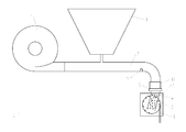
- FIG. 1 shows schematically an example of a device for conveying granular material to be applied on an agricultural surface.
- the device comprises a reservoir 1 for the puzzle-like material.
- These may in particular be seeds, but alternatively may also be granular fertilizers or granular pesticides.
- a separating device 2 which comprises an actuatable with a pressure difference separating drum 2 or disc 3, which has perforations arranged in rows of perforations. Grains of the granular material may attach to these perforations as the respective perforations move through the granular material storage area 4.
- the separating drum 3 rotates, so that the adhering to the perforations grains are sequentially passed to a dispenser 5, where they detach from the singling drum 3 and forwarded to corresponding discharge elements.
- These delivery elements may be, for example, seed coulters of a precision seed drill.
- FIG. 1 also shows a fan 6, which as well as the reservoir 1 is connected to a pneumatic conveying channel 7.
- a conveying air flow can be formed in the pneumatic conveying channel 7, which conveys the granular material from the reservoir 1 to the separating device 2.
- the conveying channel opens into the storage area 4 of the separating device 2.
- a conveyor lock 8 is arranged in the pneumatic conveying channel 7.
- the delivery rate of this delivery lock 8 is adjustable, in particular depending on the air pressure in the pneumatic delivery channel 7.
- a pressure sensor 9 can be provided upstream of the lock 8, which can determine the static and / or dynamic air pressure in the delivery channel 7.
- vent holes or openings 10 are provided in the pneumatic conveying channel 7. These vent holes 10 are arranged immediately in front of the conveyor lock 8. Air can escape from the pneumatic conveying channel 7 via these venting bores 10, unless the venting bores 10 are blocked by granular material. This can happen when the conveyor lock 8 is closed and thus the delivery rate of the conveyor lock is set to zero.
- FIGS. 2 to 4 For example, portions of the example apparatus are shown in various operating conditions.
- granular material is first conveyed from the reservoir 1 to the conveyor lock 8.
- the conveyor lock 8 is in this example in a closed state.
- the flow velocity of the air in the pneumatic conveying channel 7 is high.
- the dynamic air pressure in the pneumatic conveying channel is correspondingly high.
- the associated static air pressure is low.
- the conveyor lock 8 acts in this case as a pressure lock.
- the air pressure downstream of the conveyor lock 8 may be different from the air pressure upstream of the conveyor lock 8.
- This static air pressure is caused by a in the FIG. 3 indicated continuous pipeline 11 is passed to a connection of the conveyor lock 8.
- the high static air pressure can be used directly or indirectly to bring the conveyor lock 8 in an open state in which the flow rate is greater than zero.
- the conveyor lock 8 can be designed such that, in the opened state, it allows the granular material to pass through substantially unhindered.
- the opening of the conveyor lock 8 can in particular take place when the static air pressure in the delivery channel 7 upstream of the conveyor lock 8 exceeds a first predetermined value. This corresponds to the case that the dynamic air pressure falls below a second predetermined value.
- the conveyor lock 8 can also be opened via a drive, for example via an electric motor, when the static air pressure rises above the first predetermined value or the dynamic air pressure falls below the second predetermined value.
- the device may include a control unit, not shown here, for example in the form of an on-board computer, which controls the flow rate, here the opening state of the conveyor lock 8, depending on the specific air pressure.
- the closing can in turn be done via a drive, if a pressure sensor 9 is provided as an alternative to the continuous pipe 11. This may in particular take place when the static air pressure in the delivery channel 7 upstream of the conveyor lock 8 falls below the first predetermined value. This corresponds to the case that the dynamic air pressure rises above the second predetermined value.
- the device described above thus allows pulse-like supply of a predetermined amount of granular material of the singulator 2.
- the space requirement of the storage area 4 can be optimized.
- disturbing influences on the pressure conditions in the singulator 2 can be reduced.
- the device shown may in particular be part of a precision seed drill. This can have, in addition to the elements shown here, other elements in order to deploy the granular material on an agricultural area can.
Landscapes
- Life Sciences & Earth Sciences (AREA)
- Soil Sciences (AREA)
- Environmental Sciences (AREA)
- Sowing (AREA)
- Air Transport Of Granular Materials (AREA)
Abstract
Die Erfindung umfasst eine Vorrichtung zum Fördern von auf einer landwirtschaftlichen Fläche auszubringendem granularem Material, umfassend einen Vorratsbehälter (1) für das granulare Material, eine Vereinzelungseinrichtung (2) und einen pneumatischen Förderkanal (7) zum pneumatischen Fördern von granularem Material vom Vorratsbehälter (1) zur Vereinzelungseinrichtung (2), wobei im pneumatischen Förderkanal (7) eine Förderschleuse (8) angeordnet ist, deren Fördermenge einstellbar ist.The invention comprises a device for conveying granular material to be applied on an agricultural surface, comprising a reservoir (1) for the granular material, a separating device (2) and a pneumatic conveying channel (7) for the pneumatic conveying of granular material from the reservoir (1). to the separating device (2), wherein in the pneumatic conveying channel (7) a conveyor lock (8) is arranged, whose flow rate is adjustable.
Description
Die vorliegende Erfindung betrifft eine Vorrichtung zum Fördern von auf einer landwirtschaftlichen Fläche auszubringendem granularem Material.The present invention relates to a device for conveying granular material to be applied on an agricultural surface.
Derartige Vorrichtungen finden beispielsweise in Einzelkornsämaschinen Anwendung, um Saatgut, welches in einem zentralen Saatgutvorratsbehälter angeordnet ist, zu den einzelnen Vereinzelungsgehäusen zu transportieren. Eine solche Vorrichtung ist beispielsweise aus der
Bei den bekannten Systemen wird kontinuierlich Saatgut in die Vereinzelungsgehäuse geleitet, das sich dort zunächst in separaten Vorratsbereichen sammelt, bevor es durch die mit einer Druckdifferenz beaufschlagte Vereinzelungstrommel vereinzelt und zum Ausbringen auf dem Feld an entsprechende Säschare weitergeleitet wird.In the known systems seed is continuously fed into the separation housing, which initially collects there in separate storage areas before it is separated by the acted upon with a pressure difference singulating drum and forwarded for application in the field to corresponding coulters.
Der Vorratsbereich im Vereinzelungsgehäuse beansprucht Platz, wodurch der Raumbedarf für die Vereinzelungsgehäuse erhöht ist. Außerdem kann das im Vereinzelungsgehäuse angeordnete Saatgut die Druck- und Strömungsverhältnisse im Vereinzelungsgehäuse negativ beeinflussen.The storage area in the separation housing takes up space, which increases the space required for the separation housing. In addition, the seeds arranged in the separating housing can negatively influence the pressure and flow conditions in the separating housing.
Daher ist es Aufgabe der vorliegenden Erfindung, eine verbesserte Vorrichtung zum Fördern von auf einer landwirtschaftlichen Fläche auszubringendem granularem Material bereitzustellen. Diese Aufgabe wird durch eine Vorrichtung gemäß Patentanspruch 1 gelöst.Therefore, it is an object of the present invention to provide an improved apparatus for conveying granular material to be applied on an agricultural surface. This object is achieved by a device according to claim 1.
Durch die im Förderkanal vorgesehene Förderschleuse kann die Menge an granularem Material, die sich jeweils im Vereinzelungsgehäuse befindet, entsprechend eingestellt oder gesteuert werden. Dadurch kann verhindert werden, dass sich zu viel granulares Material gleichzeitig im Vereinzelungsgehäuse befindet und damit die Druckverhältnisse negativ beeinflusst. Gleichzeitig kann der Bereich des Vereinzelungsgehäuses, in dem das granulare Material vor der Vereinzelung angeordnet wird, räumlich kleiner dimensioniert werden.By provided in the conveyor channel conveyor lock, the amount of granular material, which is located in each case in the separation, be set or controlled accordingly. As a result, too much granular material can be prevented from being present in the singling housing at the same time and thus adversely affecting the pressure conditions. At the same time, the area of the separating housing, in which the granular material is arranged prior to singulation, can be dimensioned smaller in space.
Bei dem Vorratsbehälter kann es sich insbesondere um einen zentralen Vorratsbehälter handeln, von dem aus granulares Material an die Vereinzelungseinrichtung förderbar ist. Es können auch mehrere Vereinzelungseinrichtungen vorgesehen sein. In diesem Fall kann der Vorratsbehälter mit jeder der Vereinzelungsvorrichtungen über einen separaten pneumatischen Förderkanal zum pneumatischen Fördern von granularem Material an die jeweilige Vereinzelungseinrichtung verbunden sein. In diesem Fall kann in jedem der Förderkanäle eine entsprechende einstellbare Förderschleuse angeordnet sein.The storage container may in particular be a central storage container, from which granular material can be conveyed to the separating device. There can also be several Separating devices may be provided. In this case, the reservoir can be connected to each of the separating devices via a separate pneumatic conveying channel for the pneumatic conveying of granular material to the respective separating device. In this case, a corresponding adjustable conveyor lock can be arranged in each of the conveyor channels.
Bei dem granularen Material kann es sich insbesondere um Saatgut handeln, alternativ oder zusätzlich jedoch auch um Düngemittel oder Pestizid.The granular material may in particular be seed, alternatively or additionally, however, also fertilizer or pesticide.
Die Vereinzelungseinrichtung kann ein insbesondere mit einem Überdruck beaufschlagtes Vereinzelungsgehäuse umfassen. Das Vereinzelungsgehäuse kann einen Vorratsbereich für granulares Material aufweisen. Der Förderkanal kann dabei in das Fördergehäuse, insbesondere in den Vorratsbereich, münden.The singling device can comprise a singling housing which is acted upon in particular by an overpressure. The separating housing may have a storage area for granular material. The delivery channel can open into the delivery housing, in particular into the storage area.
Die Vereinzelungseinrichtung kann zumindest eine mit einer Druckdifferenz beaufschlagbare Vereinzelungstrommel umfassen. Die Vereinzelungstrommel kann insbesondere in Perforationsreihen angeordnete Perforationen aufweisen. An diesen Perforationen kann sich das granulare Material bei der Durchführung der Perforationen durch den Vorratsbereich anlagern, wodurch es zu einer Vereinzelung kommt.The separating device may comprise at least one separating drum which can be acted upon by a pressure difference. The singling drum may in particular have perforations arranged in rows of perforations. At these perforations, the granular material can accumulate during the perforations through the storage area, resulting in a separation.
Die Vorrichtung kann außerdem ein Gebläse umfassen, das mit dem pneumatischen Förderkanal verbunden ist. Mit Hilfe des Gebläses kann im pneumatischen Förderkanal ein entsprechender Förderluftstrom erzeugt werden, mit dem das granulare Material pneumatisch gefördert werden kann. Durch das Gebläse kann im pneumatischen Förderkanal insbesondere ein Überdruck gegenüber dem Atmosphärendruck erzeugt werden.The apparatus may also include a fan connected to the pneumatic conveying channel. With the help of the fan, a corresponding conveying air flow can be generated in the pneumatic conveying channel, with which the granular material can be conveyed pneumatically. In particular, an overpressure relative to the atmospheric pressure can be generated by the blower in the pneumatic conveying channel.
Bei der Förderschleuse kann es sich insbesondere um eine Zellenradschleuse handeln. Damit kann die Fördermenge auf besonders effektive und einfache Weise eingestellt werden.The conveyor lock may in particular be a rotary valve. Thus, the flow rate can be adjusted in a particularly effective and easy way.
Es ist jedoch auch denkbar, dass die Förderschleuse eine verschwenkbare und/oder verschiebbare Klappe umfasst, welche abhängig von ihrer Anordnung im Förderkanal die Fördermenge steuert oder regelt. Dadurch kann eine mechanisch besonders einfache Förderschleuse realisiert werden.However, it is also conceivable that the conveyor lock comprises a pivotable and / or sliding flap, which depends on their arrangement in the Delivery channel controls the flow rate or regulates. As a result, a mechanically particularly simple conveyor lock can be realized.
Als Fördermenge kann in diesem Zusammenhang insbesondere die Menge an granularem Material verstanden werden, welche durch die Förderschleuse pro Zeiteinheit von der Vorratsbehälterseite der Förderschleuse zur Vereinzelungseinrichtungsseite der Förderschleuse gefördert wird. Die Menge an granularem Material kann insbesondere der Masse des geförderten granularen Materials entsprechen.In this context, the amount of granular material which can be conveyed through the conveying sluice per unit of time from the reservoir side of the conveying sluice to the separating device side of the conveying sluice can be understood as the delivery rate. The amount of granular material may correspond in particular to the mass of the granular material conveyed.
Die Förderschleuse kann insbesondere in einen geschlossenen Zustand bringbar sein, in dem kein granulares Material von der Vorratsbehälterseite der Förderschleuse zur Vereinzelungseinrichtungsseite der Förderschleuse förderbar ist. Dadurch kann die Zufuhr von granularem Material an die Vereinzelungseinrichtung wenigstens temporär unterbrochen werden.In particular, the conveyor lock can be brought into a closed state, in which no granular material can be conveyed from the reservoir side of the conveyor lock to the separating device side of the conveyor lock. As a result, the supply of granular material to the separating device can be interrupted at least temporarily.
Die Förderschleuse kann entsprechend in einen geöffneten Zustand bringbar sein, in dem das granulare Material ungehindert oder im Wesentlichen ungehindert von der Vorratsbehälterseite der Förderschleuse zur Vereinzelungseinrichtungsseite der Förderschleuse förderbar ist.The conveyor lock can be brought accordingly into an open state, in which the granular material can be conveyed freely or substantially unhindered from the reservoir side of the conveyor lock to the separating device side of the conveyor lock.
Die Förderschleuse kann insbesondere wahlweise in die geschlossene oder in die geöffnete Position bringbar sein.The conveyor lock can in particular be selectively brought into the closed or in the open position.
Die Vorratsbehälterseite der Förderschleuse ist insbesondere stromaufwärts der Förderschleuse angeordnet während die Vereinzelungseinrichtungsseite der Förderschleuse stromabwärts der Förderschleuse angeordnet ist.The reservoir side of the conveyor lock is arranged in particular upstream of the conveyor lock while the singulator side of the conveyor lock is arranged downstream of the conveyor lock.
Die Förderschleuse kann so im Förderkanal angeordnet sein, dass stromaufwärts und stromabwärts Abschnitte des Förderkanals, insbesondere unmittelbar, angrenzen. Die Förderschleuse könnte stromabwärts jedoch auch direkt an das Vereinzelungsgehäuse der Vereinzelungseinrichtung angrenzen.The conveyor lock can be arranged in the conveyor channel, that upstream and downstream portions of the conveyor channel, in particular immediately adjacent. The conveyor lock could, however, also be located directly downstream of the singling housing of the singling device downstream.
Die Fördermenge kann insbesondere abhängig vom Luftdruck im pneumatischen Förderkanal einstellbar sein. Dadurch kann auf einfache Weise auf die Strömungsverhältnisse im Förderkanal abgestellt werden.The delivery rate can be adjustable in particular depending on the air pressure in the pneumatic delivery channel. This can be turned off in a simple manner to the flow conditions in the delivery channel.
Die Fördermenge der Förderschleuse kann also, insbesondere basierend auf dem Luftdruck im pneumatischen Förderkanal, steuerbar oder regelbar sein.The delivery rate of the delivery lock can therefore be controlled or regulated, in particular based on the air pressure in the pneumatic delivery channel.
Die Fördermenge kann insbesondere abhängig vom Luftdruck im Abschnitt des pneumatischen Förderkanals, der stromaufwärts der Förderschleuse angeordnet ist, einstellbar sein.The delivery rate can be adjustable in particular depending on the air pressure in the section of the pneumatic delivery channel which is arranged upstream of the delivery lock.
Der verwendete Luftdruck kann dabei dem dynamischen Luftdruck oder dem statischen Luftdruck entsprechen.The air pressure used can correspond to the dynamic air pressure or the static air pressure.
Der pneumatische Förderkanals kann stromaufwärts der Förderschleuse eine oder mehrere Entlüftungsbohrungen aufweisen. Durch diese Entlüftungsbohrungen kann die Förderluft aus dem pneumatischen Förderkanal entweichen, wenn sich die Förderschleuse in einem geschlossenen Zustand befindet. Erst wenn die Entlüftungsbohrungen durch das granulare Material zunehmend blockiert werden, kann die Luft nicht mehr entweichen, was zu einer Erhöhung des statischen Luftdrucks im Förderkanal führt. Basierend auf dieser Druckerhöhung kann dann beispielsweise festgestellt werden, dass sich wieder eine bestimmte Menge zu förderndes granulares Material vor der Druckschleuse angeordnet hat.The pneumatic conveying channel may have one or more ventilation holes upstream of the conveyor lock. Through these ventilation holes, the conveying air can escape from the pneumatic conveying channel when the conveyor lock is in a closed state. Only when the vent holes are increasingly blocked by the granular material, the air can not escape, resulting in an increase of the static air pressure in the delivery channel. Based on this pressure increase can then be found, for example, that again a certain amount to be conveyed granular material has arranged in front of the pressure lock.
Die eine oder mehreren Entlüftungsbohrungen oder -öffnungen können insbesondere unmittelbar stromaufwärts von der Förderschleuse angeordnet sein. Mit anderen Worten kann der Abschnitt des pneumatischen Förderkanals, der die Entlüftungsbohrungen aufweist, unmittelbar an die Förderschleuse angrenzen. Alternativ kann der mit den Entlüftungsbohrungen versehene Abschnitt auch einen vorherbestimmten Abstand von der Förderschleuse aufweisen.The one or more vent holes or openings may in particular be arranged immediately upstream of the conveyor lock. In other words, the portion of the pneumatic conveying channel, which has the vent holes, directly adjacent to the conveyor lock. Alternatively, the section provided with the vent holes may also have a predetermined distance from the conveyor lock.
Die eine oder mehreren Entlüftungsbohrungen können insbesondere einen kleineren Durchmesser aufweisen als der mittlere Durchmesser des zu fördernden granularen Materials. Dadurch kann es zu einer wenigstens teilweisen Blockierung der Entlüftungsbohrungen zum oben genannten Zweck kommen. Die eine oder mehreren Entlüftungsbohrungen können insbesondere einen Durchmesser von 1 mm bis 5 mm, bevorzugt von 3 mm, aufweisen.The one or more vent holes may in particular have a smaller diameter than the average diameter of the granular material to be delivered. This can lead to an at least partial blockage of the vent holes for the above purpose. The one or more ventilation bores may in particular have a diameter of 1 mm to 5 mm, preferably of 3 mm.
Der pneumatische Förderkanal kann über eine durchgängige Rohrleitung mit der Förderschleuse verbunden sein, wobei die durchgängige Rohrleitung stromaufwärts der Förderschleuse in den pneumatischen Förderkanal mündet und wobei der statische Luftdruck in der durchgängigen Rohrleitung direkt oder indirekt die Fördermenge der Förderschleuse bestimmt. Mit Hilfe der durchgängigen Rohrleitung kann auf einfache Weise der statische Luftdruck im pneumatischen Förderkanal bestimmt werden. Der sich auf die durchgängige Rohrleitung übertragende statische Luftdruck kann direkt oder unmittelbar verwendet werden, um ein mechanisches Element der Förderschleuse zu beeinflussen und damit die Fördermenge zu bestimmen. Mit anderen Worten kann die Förderschleuse durch den Luftdruck in der durchgängigen Rohrleitung geschaltet werden.The pneumatic conveying channel can be connected via a continuous pipe with the conveyor lock, wherein the continuous pipe upstream of the conveyor lock opens into the pneumatic conveying channel and wherein the static air pressure in the continuous pipe directly or indirectly determines the flow rate of the conveyor lock. With the help of the continuous pipeline, the static air pressure in the pneumatic delivery channel can be determined in a simple manner. The static air pressure transmitted to the continuous pipeline can be used directly or directly to influence a mechanical element of the conveyor lock and thus to determine the flow rate. In other words, the conveyor lock can be switched by the air pressure in the continuous pipe.
Beispielsweise kann bei einem hohen statischen Luftdruck eine Klappe der Förderschleuse verschwenken, so dass der Durchgang durch die Förderschleuse freigegeben wird. Andererseits, wenn der statische Luftdruck wieder abfällt, kann die Klappe wieder in ihre Ausgangsposition zurückfallen, in der der pneumatische Förderkanal verschlossen wird, so dass die Fördermenge gleich null wird.For example, at a high static air pressure, a flap of the conveyor lock can pivot, so that the passage through the conveyor lock is released. On the other hand, when the static air pressure drops again, the flap can fall back to its original position, in which the pneumatic conveying channel is closed, so that the flow rate becomes zero.
Die durchgängige Rohrleitung kann insbesondere senkrecht in den Förderkanal münden.The continuous pipeline can in particular open vertically into the delivery channel.
Durchgängig kann in diesem Fall insbesondere bedeuten, dass der an der Mündung der Rohrleitung in den Förderkanal vorherrschende Luftdruck unverändert oder im Wesentlichen unverändert am Anschluss der Rohrleitung an die Förderschleuse anliegt.Throughout this case, it may in particular mean that the air pressure prevailing at the mouth of the pipeline into the conveying channel remains unchanged or essentially unchanged at the connection of the pipeline to the conveying lock.
Alternativ oder zusätzlich kann die Vorrichtung auch einen Drucksensor umfassen, der stromaufwärts der Förderschleuse angeordnet ist, wobei mit dem Drucksensor der Luftdruck im pneumatischen Förderkanal bestimmbar ist. Der Drucksensor kann den dynamischen und/oder den statischen Luftdruck im pneumatischen Förderkanal bestimmen. Der Drucksensor kann auch ein elektronischer Luftdrucksensor sein.Alternatively or additionally, the device may also comprise a pressure sensor, which is arranged upstream of the conveyor lock, wherein the air pressure in the pneumatic conveying channel can be determined with the pressure sensor. The pressure sensor can determine the dynamic and / or the static air pressure in the pneumatic delivery channel. The pressure sensor may also be an electronic air pressure sensor.
Die Fördermenge der Förderschleuse kann in Abhängigkeit von dem vom Drucksensor bestimmten Wert einstellbar sein, insbesondere elektronisch. Beispielsweise kann ein Antrieb der Förderschleuse, beispielsweise einer Zellenradschleuse, in Abhängigkeit von dem bestimmten Druckwert einstellbar sein.The delivery rate of the delivery lock can be adjustable as a function of the value determined by the pressure sensor, in particular electronically. For example, a drive of the conveyor lock, for example a rotary valve, be adjustable depending on the specific pressure value.
Alternativ oder zusätzlich zum Drucksensor kann auch ein Sensor zur Bestimmung der Strömungsgeschwindigkeit der Förderluft im Förderkanal vorgesehen sein, welcher insbesondere stromaufwärts der Förderschleuse angeordnet ist. Aufgrund des Zusammenhangs der Strömungsgeschwindigkeit mit dem dynamischen Luftdruck im Förderkanal kann die Vorrichtung so ausgebildet sein, dass der dynamische Luftdruck basierend auf der bestimmten Strömungsgeschwindigkeit bestimmbar ist.As an alternative or in addition to the pressure sensor, it is also possible to provide a sensor for determining the flow velocity of the conveying air in the conveying channel, which is arranged in particular upstream of the conveying lock. Due to the relationship between the flow velocity and the dynamic air pressure in the delivery channel, the device can be designed such that the dynamic air pressure can be determined based on the determined flow velocity.
Alternativ kann die Vorrichtung auch so ausgebildet sein, dass die Fördermenge der Förderschleuse basierend auf der bestimmten Strömungsgeschwindigkeit einstellbar ist. Aufgrund des Zusammenhangs von Luftdruck und Strömungsgeschwindigkeit ist auch dann die Fördermenge im obigen Sinne basierend auf dem Luftdruck im Förderkanal einstellbar.Alternatively, the device may also be designed so that the delivery rate of the delivery lock can be set based on the determined flow rate. Due to the relationship between air pressure and flow velocity, the delivery rate in the above sense is adjustable based on the air pressure in the delivery channel.
Alternativ oder zusätzlich kann auch ein Sensor zur Bestimmung der Menge an granularem Material, das vom Vorratsbehälter zur Förderschleuse gefördert wird, vorgesehen sein. Auch diese Größe steht mit der Strömungsgeschwindigkeit und damit mit dem dynamischen Luftdruck in Zusammenhang. Somit kann die Vorrichtung so ausgebildet sein, dass der dynamische Luftdruck basierend auf der bestimmten Menge an gefördertem granularem Material bestimmbar ist.Alternatively or additionally, a sensor for determining the amount of granular material, which is conveyed from the reservoir to the conveyor lock, may be provided. This size is also related to the flow velocity and thus to the dynamic air pressure. Thus, the device may be configured such that the dynamic air pressure can be determined based on the determined amount of granular material conveyed.
Alternativ kann die Vorrichtung auch so ausgebildet sein, dass die Fördermenge der Förderschleuse basierend auf der bestimmten Menge an gefördertem granularem Material einstellbar ist. Aufgrund des Zusammenhangs von Luftdruck und Menge an gefördertem granularem Material ist auch dann die Fördermenge im obigen Sinne basierend auf dem Luftdruck im Förderkanal einstellbar.Alternatively, the device may also be designed so that the delivery rate of the conveyor lock can be set based on the specific amount of granular material conveyed. Due to the relationship between the air pressure and the amount of granular material conveyed, the delivery rate in the above sense can also be adjusted based on the air pressure in the delivery channel.
Die Vorrichtung kann insbesondere derart ausgebildet sein, dass die Fördermenge null ist, wenn der statische Luftdruck unter einem ersten vorherbestimmten Wert oder der dynamische Luftdruck über einem zweiten vorherbestimmten Wert liegt, während sie größer null ist, wenn der statische Luftdruck über dem ersten vorherbestimmten Wert oder der dynamische Luftdruck unter dem zweiten vorherbestimmten Wert liegt. Dadurch kann erreicht werden, dass der Vereinzelungseinrichtung pulsartig oder intermittierend eine gewisse, vorherbestimmte Menge an granularem Material zugeführt wird.In particular, the device may be configured such that the delivery rate is zero when the static air pressure is below a first predetermined value or the dynamic air pressure is above a second predetermined value, while greater than zero when the static air pressure is above the first predetermined value or the dynamic air pressure is below the second predetermined value. It can thereby be achieved that the singulation device is supplied in a pulse-like or intermittent manner to a certain, predetermined amount of granular material.
Wird die Strömungsgeschwindigkeit als Steuergröße verwendet, kann die Vorrichtung derart ausgebildet sein, dass die Fördermenge null ist, wenn die Strömungsgeschwindigkeit über einem dritten vorherbestimmten Wert liegt, während sie größer null ist, wenn die Strömungsgeschwindigkeit unter dem dritten vorherbestimmten Wert liegt.When the flow rate is used as a control variable, the apparatus may be configured such that the delivery rate is zero when the flow rate is above a third predetermined value while greater than zero when the flow rate is below the third predetermined value.
Wird die Menge an granularem Material, die vom Vorratsbehälter zur Förderschleuse gefördert wird als Steuergröße verwendet, kann die Vorrichtung derart ausgebildet sein, dass die Fördermenge null ist, wenn die Menge an granularem Material über einem vierten vorherbestimmten Wert liegt, während sie größer null ist, wenn die Menge an granularem Material unter dem vierten vorherbestimmten Wert liegt.When the amount of granular material conveyed from the reservoir to the delivery lock is used as the control variable, the apparatus may be configured such that the delivery rate is zero when the amount of granular material is above a fourth predetermined value while being greater than zero, when the amount of granular material is below the fourth predetermined value.
Die Förderschleuse kann auch als Druckschleuse wirken, welche insbesondere im geschlossenen Zustand den Bereich des Förderkanals stromaufwärts der Förderschleuse vom Bereich stromabwärts der Förderschleuse pneumatisch trennt. Dadurch kann die Beeinflussung des Luftdrucks in der Vereinzelungseinrichtung durch den Luftdruck im pneumatischen Förderkanal weiter verringert werden.The conveyor lock can also act as a pressure lock, which, especially in the closed state, pneumatically separates the area of the conveyor channel upstream of the conveyor lock from the area downstream of the conveyor lock. As a result, the influence of the air pressure in the separating device can be further reduced by the air pressure in the pneumatic conveying channel.
Die oben genannte Vorrichtung kann insbesondere Teil eines landwirtschaftlichen Geräts zum Ausbringen von granularem Material auf einer landwirtschaftlichen Fläche sein. Bei dem landwirtschaftlichen Gerät kann es sich insbesondere um eine Einzelkornsämaschine handeln.In particular, the above device may be part of an agricultural implement for applying granular material to an agricultural surface. The agricultural implement may in particular be a precision seed drill.
Mit anderen Worten stellt die Erfindung außerdem eine Einzelkornsämaschine bereits, welche eine der oben genannten Vorrichtungen umfasst.In other words, the invention also provides a precision seed drill already comprising one of the above-mentioned devices.
Die Erfindung stellt also insbesondere eine Einzelkornsämaschine bereit umfassend:
- einen Vorratsbehälter für das granulare Material,
- eine Vereinzelungseinrichtung und
- einen pneumatischen Förderkanal zum pneumatischen Fördern von granularem Material vom Vorratsbehälter zur Vereinzelungseinrichtung,
- wobei im pneumatischen Förderkanal eine Förderschleuse angeordnet ist, deren Fördermenge einstellbar ist.
- a reservoir for the granular material,
- a separating device and
- a pneumatic conveying channel for the pneumatic conveying of granular material from the reservoir to the separating device,
- wherein in the pneumatic conveying channel a conveyor lock is arranged, the flow rate is adjustable.
Die Vorrichtung, welche Teil des landwirtschaftlichen Geräts, insbesondere Teil der Einzelkornsämaschine ist, kann eines oder mehrere der oben genannten Merkmale aufweisen.The device, which is part of the agricultural implement, in particular part of the precision seed drill, may have one or more of the above-mentioned features.
Die Erfindung stellt außerdem ein Verfahrens zum Fördern von granularem Material in einem landwirtschaftlichen Gerät zum Ausbringen von granularem Material auf einer landwirtschaftlichen Fläche bereit, umfassend die Schritte:The invention also provides a method for conveying granular material in an agricultural implement for spreading granular material on an agricultural surface, comprising the steps of:
Bereitstellen einer oben genannten Vorrichtung oder eines oben genannten landwirtschaftlichen Geräts,Providing an above-mentioned device or agricultural device,
Bestimmen des Luftdrucks im pneumatischen Förderkanal stromaufwärts der Förderschleuse undDetermining the air pressure in the pneumatic conveying channel upstream of the conveyor lock and
Einstellen der Fördermenge der Förderschleuse basierend auf dem bestimmten Luftdruck.Adjusting the delivery rate of the conveyor lock based on the determined air pressure.
Das Verfahren kann außerdem ein, insbesondere kontinuierliches, Zuführen von granularem Material an den pneumatischen Förderkanal aus dem Vorratsbehälter umfassen.The method may also include, in particular, continuously feeding granular material to the pneumatic conveying channel from the reservoir.
Das Einstellen der Fördermenge kann insbesondere ein Öffnen und Schließen der Förderschleuse umfassen.The adjustment of the delivery rate may include, in particular, an opening and closing of the delivery lock.
Alternativ zum Luftdruck kann auch die Strömungsgeschwindigkeit der Förderluft stromaufwärts der Förderschleuse und/oder die Menge an granularem Material, das vom Vorratsbehälter zur Förderschleuse gefördert wird, bestimmt werden und die Fördermenge der Förderschleuse basierend darauf eingestellt werden.As an alternative to the air pressure, the flow rate of the conveying air upstream of the conveying lock and / or the amount of granular material conveyed from the reservoir to the conveying lock can also be determined and the delivery rate of the conveying lock can be adjusted based thereon.
Weitere Merkmale und Vorteile der Erfindung werden nachfolgend anhand der beispielhaften Figuren erläutert. Dabei zeigt
- Fig. 1
- eine schematische Darstellung einer erfindungsgemäßen Vorrichtung;
- Fig. 2
- Teile der erfindungsgemäßen Vorrichtung in einem ersten Betriebszustand;
- Fig. 3
- Teile der erfindungsgemäßen Vorrichtung in einem zweiten Betriebszustand; und
- Fig. 4
- Teile der erfindungsgemäßen Vorrichtung in einem dritten Betriebszustand.
- Fig. 1
- a schematic representation of a device according to the invention;
- Fig. 2
- Parts of the device according to the invention in a first operating state;
- Fig. 3
- Parts of the device according to the invention in a second operating state; and
- Fig. 4
- Parts of the device according to the invention in a third operating state.
Außerdem ist eine Vereinzelungseinrichtung 2 vorgesehen, welche eine mit einer Druckdifferenz beaufschlagbare Vereinzelungstrommel 2 oder -scheibe 3 umfasst, welche in Perforationsreihen angeordnete Perforationen aufweist. An diesen Perforationen können sich Körner des granularen Materials anlagern, wenn sich die entsprechenden Perforationen durch den Vorratsbereich 4 für das granulare Material bewegen.In addition, a
Die Vereinzelungstrommel 3 dreht sich, so dass die an den Perforationen anhaftenden Körner sequenziell an einer Abgabeeinrichtung 5 vorbeigeführt werden, wo sie sich von der Vereinzelungstrommel 3 lösen und an entsprechende Abgabeelemente weitergeleitet werden. Bei diesen Abgabeelementen, hier nicht dargestellt, kann es sich beispielsweise um Säschare einer Einzelkornsämaschine handeln.The separating drum 3 rotates, so that the adhering to the perforations grains are sequentially passed to a dispenser 5, where they detach from the singling drum 3 and forwarded to corresponding discharge elements. These delivery elements, not shown here, may be, for example, seed coulters of a precision seed drill.
Durch das Gebläse 6 wird im pneumatischen Förderkanal 7 ein Luftüberdruck gegenüber dem Atmosphärendruck erzeugt.By the fan 6, an air pressure over the atmospheric pressure is generated in the pneumatic conveying
Im pneumatischen Förderkanal 7 ist eine Förderschleuse 8 angeordnet. Die Fördermenge dieser Förderschleuse 8 ist einstellbar, insbesondere abhängig vom Luftdruck im pneumatischen Förderkanal 7.In the pneumatic conveying
Zur Bestimmung dieses Luftdrucks kann stromaufwärts der Schleuse 8 ein Drucksensor 9 vorgesehen sein, welcher den statischen und/oder dynamischen Luftdruck im Förderkanal 7 bestimmen kann.To determine this air pressure, a pressure sensor 9 can be provided upstream of the
Ebenfalls stromaufwärts von der Förderschleuse 8 sind Entlüftungsbohrungen oder -öffnungen 10 im pneumatischen Förderkanal 7 vorgesehen. Diese Entlüftungsbohrungen 10 sind unmittelbar vor der Förderschleuse 8 angeordnet. Über diese Entlüftungsbohrungen 10 kann Luft aus dem pneumatischen Förderkanal 7 entweichen, es sei denn, die Entlüftungsbohrungen 10 werden durch granulares Material blockiert. Dazu kann es kommen, wenn die Förderschleuse 8 verschlossen ist und somit die Fördermenge der Förderschleuse auf null eingestellt ist.Also upstream of the
In den
Im Betriebszustand der
Da die Entlüftungsbohrungen 10 freiliegen, ist die Strömungsgeschwindigkeit der Luft im pneumatischen Förderkanal 7 hoch. Damit ist auch der dynamische Luftdruck im pneumatischen Förderkanal entsprechend hoch. Der zugehörige statische Luftdruck ist dagegen gering.Since the vent holes 10 are exposed, the flow velocity of the air in the pneumatic conveying
Die Förderschleuse 8 wirkt in diesem Fall auch als Druckschleuse. Mit anderen Worten kann der Luftdruck stromabwärts der Förderschleuse 8 unterschiedlich sein zu dem Luftdruck stromaufwärts der Förderschleuse 8.The
In dem Betriebszustand der
Dieser statische Luftdruck wird durch eine in der
Das Öffnen der Förderschleuse 8 kann insbesondere stattfinden, wenn der statische Luftdruck im Förderkanal 7 stromaufwärts der Förderschleuse 8 einen ersten vorherbestimmten Wert übersteigt. Dies entspricht dem Fall, dass der dynamische Luftdruck unter einen zweiten vorherbestimmten Wert fällt.The opening of the
Wenn anstelle der durchgängigen Rohrleitung 11 ein Drucksensor 9 wie in
Durch das Öffnen der Förderschleuse 8 wird die stromaufwärts der Förderschleuse 8 angesammelte Menge an granularem Material an die Vereinzelungseinrichtung 2 weitergeleitet. Dadurch werden die Entlüftungsbohrungen 10 wieder freigegeben, wie in
Damit kann Luft wieder durch die Entlüftungsbohrungen 10 entweichen, wodurch der statische Luftdruck fällt und der dynamische Luftdruck im pneumatischen Förderkanal 7 steigt. Durch das Steigen des dynamischen Luftdrucks steigt auch wieder die Strömungsgeschwindigkeit der Luft im pneumatischen Förderkanal, wodurch wieder granulares Material vom Vorratsbehälter 1 zur Förderschleuse 8 gefördert wird, die daraufhin wieder in einen geschlossenen Zustand gebracht wird, in dem kein granulares Material von der Förderschleuse 8 zur Vereinzelungseinrichtung 2 gefördert wird.This allows air to escape again through the vent holes 10, whereby the static air pressure drops and the dynamic air pressure in the pneumatic conveying
Das Verschließen kann wiederum über einen Antrieb geschehen, wenn alternativ zur durchgängigen Rohrleitung 11 ein Drucksensor 9 vorgesehen ist. Dies kann insbesondere stattfinden, wenn der statische Luftdruck im Förderkanal 7 stromaufwärts der Förderschleuse 8 unter den ersten vorherbestimmten Wert fällt. Dies entspricht dem Fall, dass der dynamische Luftdruck über den zweiten vorherbestimmten Wert steigt.The closing can in turn be done via a drive, if a pressure sensor 9 is provided as an alternative to the
Die oben beschriebene Vorrichtung erlaubt es also, pulsartig eine vorherbestimmte Menge von granularem Material der Vereinzelungseinrichtung 2 zuzuführen. Dadurch ist die Menge an granularem Material, die sich jeweils gleichzeitig in der Vereinzelungseinrichtung 2 befindet, einstellbar. Dadurch kann wiederum der Raumbedarf des Vorratsbereichs 4 optimiert werden. Außerdem können störende Beeinflussungen der Druckverhältnisse in der Vereinzelungseinrichtung 2 reduziert werden.The device described above thus allows pulse-like supply of a predetermined amount of granular material of the
Die gezeigte Vorrichtung kann insbesondere Teil einer Einzelkornsämaschine sein. Diese kann neben den hier gezeigten Elementen noch weitere Elemente aufweisen, um das granulare Material auf einer landwirtschaftlichen Fläche ausbringen zu können.The device shown may in particular be part of a precision seed drill. This can have, in addition to the elements shown here, other elements in order to deploy the granular material on an agricultural area can.
Es versteht sich, dass in den zuvor beschriebenen Ausführungsbeispielen genannte Merkmale nicht auf diese speziellen Kombinationen beschränkt sind und auch in beliebigen anderen Kombinationen möglich sind.It is understood that in the embodiments described above mentioned features are not limited to these specific combinations and are also possible in any other combinations.
Claims (10)
Applications Claiming Priority (1)
| Application Number | Priority Date | Filing Date | Title |
|---|---|---|---|
| DE102014103971.8A DE102014103971A1 (en) | 2014-03-24 | 2014-03-24 | Device for conveying granular material |
Publications (2)
| Publication Number | Publication Date |
|---|---|
| EP2923545A1 true EP2923545A1 (en) | 2015-09-30 |
| EP2923545B1 EP2923545B1 (en) | 2017-06-07 |
Family
ID=52875087
Family Applications (1)
| Application Number | Title | Priority Date | Filing Date |
|---|---|---|---|
| EP15401019.3A Active EP2923545B1 (en) | 2014-03-24 | 2015-03-17 | Device for conveying granular material |
Country Status (2)
| Country | Link |
|---|---|
| EP (1) | EP2923545B1 (en) |
| DE (1) | DE102014103971A1 (en) |
Cited By (4)
| Publication number | Priority date | Publication date | Assignee | Title |
|---|---|---|---|---|
| EP3235361A1 (en) * | 2016-04-21 | 2017-10-25 | Amazonen-Werke H. Dreyer GmbH & Co. KG | Dosing device for granular material with regulated central doser |
| EP3718388A1 (en) * | 2019-04-05 | 2020-10-07 | Horsch Maschinen GmbH | Agricultural device with metering devices comprising three compressed air feeds |
| US10820484B2 (en) | 2018-09-07 | 2020-11-03 | Cnh Industrial Canada, Ltd. | Air cart product flow condition monitoring |
| CN112056053A (en) * | 2020-09-14 | 2020-12-11 | 孙照 | Even seeder of hickory chick |
Citations (3)
| Publication number | Priority date | Publication date | Assignee | Title |
|---|---|---|---|---|
| US20070022928A1 (en) * | 2005-08-01 | 2007-02-01 | Cnh Canada, Ltd. | Vacuum control for seed planter |
| FR2973790A1 (en) * | 2011-04-11 | 2012-10-12 | Kuhn Sa | DEVICE FOR REMOTELY SUPPLYING AUXILIARY TANKS AND SEEDER USING SUCH A FEEDING DEVICE |
| EP2298056B1 (en) | 2009-09-10 | 2012-11-28 | Amazonen-Werke H. Dreyer GmbH & Co. KG | Refilling system |
-
2014
- 2014-03-24 DE DE102014103971.8A patent/DE102014103971A1/en active Pending
-
2015
- 2015-03-17 EP EP15401019.3A patent/EP2923545B1/en active Active
Patent Citations (3)
| Publication number | Priority date | Publication date | Assignee | Title |
|---|---|---|---|---|
| US20070022928A1 (en) * | 2005-08-01 | 2007-02-01 | Cnh Canada, Ltd. | Vacuum control for seed planter |
| EP2298056B1 (en) | 2009-09-10 | 2012-11-28 | Amazonen-Werke H. Dreyer GmbH & Co. KG | Refilling system |
| FR2973790A1 (en) * | 2011-04-11 | 2012-10-12 | Kuhn Sa | DEVICE FOR REMOTELY SUPPLYING AUXILIARY TANKS AND SEEDER USING SUCH A FEEDING DEVICE |
Cited By (4)
| Publication number | Priority date | Publication date | Assignee | Title |
|---|---|---|---|---|
| EP3235361A1 (en) * | 2016-04-21 | 2017-10-25 | Amazonen-Werke H. Dreyer GmbH & Co. KG | Dosing device for granular material with regulated central doser |
| US10820484B2 (en) | 2018-09-07 | 2020-11-03 | Cnh Industrial Canada, Ltd. | Air cart product flow condition monitoring |
| EP3718388A1 (en) * | 2019-04-05 | 2020-10-07 | Horsch Maschinen GmbH | Agricultural device with metering devices comprising three compressed air feeds |
| CN112056053A (en) * | 2020-09-14 | 2020-12-11 | 孙照 | Even seeder of hickory chick |
Also Published As
| Publication number | Publication date |
|---|---|
| EP2923545B1 (en) | 2017-06-07 |
| DE102014103971A1 (en) | 2015-09-24 |
Similar Documents
| Publication | Publication Date | Title |
|---|---|---|
| EP3335535B1 (en) | Device for conveying granular material to be applied to an agricultural area, with even singulating pressure | |
| EP3777500B1 (en) | Method for applying granular material | |
| EP1329149B1 (en) | Sowing maschine | |
| DE202018006221U1 (en) | Separation device for pressure difference-based singulation of grains and agricultural row unit | |
| EP2591656B1 (en) | Refilling system | |
| DE102017103640A1 (en) | Method and control system for an agricultural distribution machine for dosing and discharging granular material | |
| EP2923545B1 (en) | Device for conveying granular material | |
| EP3050418A1 (en) | Dosing system of an agricultural machine | |
| DE102015101256A1 (en) | Dosing system of an agricultural machine | |
| DE102015121600A1 (en) | Method and device for discharging granular material | |
| EP3127415A1 (en) | Method for dosing granular goods, and control system for a dosing unit of a distributing and/or sowing device | |
| WO2021069607A1 (en) | Agricultural distributing machine having simultaneously hybridly operable singulating devices | |
| WO2020200672A1 (en) | Supply assembly for a pneumatic grain separator device | |
| DE102019127469A1 (en) | Agricultural distributing machine with speed and / or seed type-dependent variable compressed air flow speed | |
| EP2368415B1 (en) | Pneumatic single grain seeder | |
| EP3108732B1 (en) | Device for conveying granular material onto an agricultural surface with reduced discharge pressure | |
| EP3662733B1 (en) | Agricultural distribution machine and dosing device for agricultural distributor | |
| EP3225093A1 (en) | Pneumatic distributor and closure element for the same | |
| EP3292747B1 (en) | Seed drill with singulating device | |
| DE202019107077U1 (en) | Agricultural device with metering devices comprising three compressed air feeds | |
| EP3704923B1 (en) | Assembly for an agricultural seeding machine, method for separating seed grains in an arrangement for an agricultural seeding machine and seeding machine | |
| DE202004004381U1 (en) | Pneumatically operated distribution machine for distributing granular material, especially seed or fertilizer, comprises a dosing chamber sealed in an extensively pressure-tight manner | |
| EP3718388B1 (en) | Agricultural device with metering devices comprising three compressed air feeds | |
| EP3108734B1 (en) | Device for conveying granular material to be applied to an agricultural area, with improved pneumatic conveyance | |
| DE102015110009A1 (en) | Device for conveying granular material with improved air flow to be applied on an agricultural surface |
Legal Events
| Date | Code | Title | Description |
|---|---|---|---|
| PUAI | Public reference made under article 153(3) epc to a published international application that has entered the european phase |
Free format text: ORIGINAL CODE: 0009012 |
|
| AK | Designated contracting states |
Kind code of ref document: A1 Designated state(s): AL AT BE BG CH CY CZ DE DK EE ES FI FR GB GR HR HU IE IS IT LI LT LU LV MC MK MT NL NO PL PT RO RS SE SI SK SM TR |
|
| AX | Request for extension of the european patent |
Extension state: BA ME |
|
| RIN1 | Information on inventor provided before grant (corrected) |
Inventor name: WIEN, THOMAS Inventor name: BRUEGGEMANN, KLAUS |
|
| 17P | Request for examination filed |
Effective date: 20160223 |
|
| RBV | Designated contracting states (corrected) |
Designated state(s): AL AT BE BG CH CY CZ DE DK EE ES FI FR GB GR HR HU IE IS IT LI LT LU LV MC MK MT NL NO PL PT RO RS SE SI SK SM TR |
|
| GRAP | Despatch of communication of intention to grant a patent |
Free format text: ORIGINAL CODE: EPIDOSNIGR1 |
|
| INTG | Intention to grant announced |
Effective date: 20170210 |
|
| GRAJ | Information related to disapproval of communication of intention to grant by the applicant or resumption of examination proceedings by the epo deleted |
Free format text: ORIGINAL CODE: EPIDOSDIGR1 |
|
| GRAP | Despatch of communication of intention to grant a patent |
Free format text: ORIGINAL CODE: EPIDOSNIGR1 |
|
| GRAS | Grant fee paid |
Free format text: ORIGINAL CODE: EPIDOSNIGR3 |
|
| INTC | Intention to grant announced (deleted) | ||
| INTG | Intention to grant announced |
Effective date: 20170412 |
|
| AK | Designated contracting states |
Kind code of ref document: B1 Designated state(s): AL AT BE BG CH CY CZ DE DK EE ES FI FR GB GR HR HU IE IS IT LI LT LU LV MC MK MT NL NO PL PT RO RS SE SI SK SM TR |
|
| REG | Reference to a national code |
Ref country code: GB Ref legal event code: FG4D Free format text: NOT ENGLISH |
|
| GRAA | (expected) grant |
Free format text: ORIGINAL CODE: 0009210 |
|
| REG | Reference to a national code |
Ref country code: CH Ref legal event code: EP Ref country code: AT Ref legal event code: REF Ref document number: 898491 Country of ref document: AT Kind code of ref document: T Effective date: 20170615 |
|
| REG | Reference to a national code |
Ref country code: IE Ref legal event code: FG4D Free format text: LANGUAGE OF EP DOCUMENT: GERMAN |
|
| REG | Reference to a national code |
Ref country code: DE Ref legal event code: R096 Ref document number: 502015001174 Country of ref document: DE |
|
| REG | Reference to a national code |
Ref country code: NL Ref legal event code: MP Effective date: 20170607 |
|
| REG | Reference to a national code |
Ref country code: LT Ref legal event code: MG4D |
|
| PG25 | Lapsed in a contracting state [announced via postgrant information from national office to epo] |
Ref country code: GR Free format text: LAPSE BECAUSE OF FAILURE TO SUBMIT A TRANSLATION OF THE DESCRIPTION OR TO PAY THE FEE WITHIN THE PRESCRIBED TIME-LIMIT Effective date: 20170908 Ref country code: HR Free format text: LAPSE BECAUSE OF FAILURE TO SUBMIT A TRANSLATION OF THE DESCRIPTION OR TO PAY THE FEE WITHIN THE PRESCRIBED TIME-LIMIT Effective date: 20170607 Ref country code: LT Free format text: LAPSE BECAUSE OF FAILURE TO SUBMIT A TRANSLATION OF THE DESCRIPTION OR TO PAY THE FEE WITHIN THE PRESCRIBED TIME-LIMIT Effective date: 20170607 Ref country code: ES Free format text: LAPSE BECAUSE OF FAILURE TO SUBMIT A TRANSLATION OF THE DESCRIPTION OR TO PAY THE FEE WITHIN THE PRESCRIBED TIME-LIMIT Effective date: 20170607 Ref country code: NO Free format text: LAPSE BECAUSE OF FAILURE TO SUBMIT A TRANSLATION OF THE DESCRIPTION OR TO PAY THE FEE WITHIN THE PRESCRIBED TIME-LIMIT Effective date: 20170907 Ref country code: FI Free format text: LAPSE BECAUSE OF FAILURE TO SUBMIT A TRANSLATION OF THE DESCRIPTION OR TO PAY THE FEE WITHIN THE PRESCRIBED TIME-LIMIT Effective date: 20170607 |
|
| PG25 | Lapsed in a contracting state [announced via postgrant information from national office to epo] |
Ref country code: LV Free format text: LAPSE BECAUSE OF FAILURE TO SUBMIT A TRANSLATION OF THE DESCRIPTION OR TO PAY THE FEE WITHIN THE PRESCRIBED TIME-LIMIT Effective date: 20170607 Ref country code: SE Free format text: LAPSE BECAUSE OF FAILURE TO SUBMIT A TRANSLATION OF THE DESCRIPTION OR TO PAY THE FEE WITHIN THE PRESCRIBED TIME-LIMIT Effective date: 20170607 Ref country code: RS Free format text: LAPSE BECAUSE OF FAILURE TO SUBMIT A TRANSLATION OF THE DESCRIPTION OR TO PAY THE FEE WITHIN THE PRESCRIBED TIME-LIMIT Effective date: 20170607 Ref country code: BG Free format text: LAPSE BECAUSE OF FAILURE TO SUBMIT A TRANSLATION OF THE DESCRIPTION OR TO PAY THE FEE WITHIN THE PRESCRIBED TIME-LIMIT Effective date: 20170907 Ref country code: NL Free format text: LAPSE BECAUSE OF FAILURE TO SUBMIT A TRANSLATION OF THE DESCRIPTION OR TO PAY THE FEE WITHIN THE PRESCRIBED TIME-LIMIT Effective date: 20170607 |
|
| PG25 | Lapsed in a contracting state [announced via postgrant information from national office to epo] |
Ref country code: CZ Free format text: LAPSE BECAUSE OF FAILURE TO SUBMIT A TRANSLATION OF THE DESCRIPTION OR TO PAY THE FEE WITHIN THE PRESCRIBED TIME-LIMIT Effective date: 20170607 Ref country code: EE Free format text: LAPSE BECAUSE OF FAILURE TO SUBMIT A TRANSLATION OF THE DESCRIPTION OR TO PAY THE FEE WITHIN THE PRESCRIBED TIME-LIMIT Effective date: 20170607 Ref country code: RO Free format text: LAPSE BECAUSE OF FAILURE TO SUBMIT A TRANSLATION OF THE DESCRIPTION OR TO PAY THE FEE WITHIN THE PRESCRIBED TIME-LIMIT Effective date: 20170607 Ref country code: SK Free format text: LAPSE BECAUSE OF FAILURE TO SUBMIT A TRANSLATION OF THE DESCRIPTION OR TO PAY THE FEE WITHIN THE PRESCRIBED TIME-LIMIT Effective date: 20170607 |
|
| REG | Reference to a national code |
Ref country code: FR Ref legal event code: PLFP Year of fee payment: 4 |
|
| PG25 | Lapsed in a contracting state [announced via postgrant information from national office to epo] |
Ref country code: IS Free format text: LAPSE BECAUSE OF FAILURE TO SUBMIT A TRANSLATION OF THE DESCRIPTION OR TO PAY THE FEE WITHIN THE PRESCRIBED TIME-LIMIT Effective date: 20171007 Ref country code: SM Free format text: LAPSE BECAUSE OF FAILURE TO SUBMIT A TRANSLATION OF THE DESCRIPTION OR TO PAY THE FEE WITHIN THE PRESCRIBED TIME-LIMIT Effective date: 20170607 Ref country code: PL Free format text: LAPSE BECAUSE OF FAILURE TO SUBMIT A TRANSLATION OF THE DESCRIPTION OR TO PAY THE FEE WITHIN THE PRESCRIBED TIME-LIMIT Effective date: 20170607 Ref country code: IT Free format text: LAPSE BECAUSE OF FAILURE TO SUBMIT A TRANSLATION OF THE DESCRIPTION OR TO PAY THE FEE WITHIN THE PRESCRIBED TIME-LIMIT Effective date: 20170607 |
|
| REG | Reference to a national code |
Ref country code: DE Ref legal event code: R097 Ref document number: 502015001174 Country of ref document: DE |
|
| PLBE | No opposition filed within time limit |
Free format text: ORIGINAL CODE: 0009261 |
|
| STAA | Information on the status of an ep patent application or granted ep patent |
Free format text: STATUS: NO OPPOSITION FILED WITHIN TIME LIMIT |
|
| PG25 | Lapsed in a contracting state [announced via postgrant information from national office to epo] |
Ref country code: DK Free format text: LAPSE BECAUSE OF FAILURE TO SUBMIT A TRANSLATION OF THE DESCRIPTION OR TO PAY THE FEE WITHIN THE PRESCRIBED TIME-LIMIT Effective date: 20170607 |
|
| 26N | No opposition filed |
Effective date: 20180308 |
|
| PG25 | Lapsed in a contracting state [announced via postgrant information from national office to epo] |
Ref country code: SI Free format text: LAPSE BECAUSE OF FAILURE TO SUBMIT A TRANSLATION OF THE DESCRIPTION OR TO PAY THE FEE WITHIN THE PRESCRIBED TIME-LIMIT Effective date: 20170607 |
|
| PG25 | Lapsed in a contracting state [announced via postgrant information from national office to epo] |
Ref country code: MT Free format text: LAPSE BECAUSE OF FAILURE TO SUBMIT A TRANSLATION OF THE DESCRIPTION OR TO PAY THE FEE WITHIN THE PRESCRIBED TIME-LIMIT Effective date: 20170607 |
|
| REG | Reference to a national code |
Ref country code: CH Ref legal event code: PL |
|
| PG25 | Lapsed in a contracting state [announced via postgrant information from national office to epo] |
Ref country code: MC Free format text: LAPSE BECAUSE OF FAILURE TO SUBMIT A TRANSLATION OF THE DESCRIPTION OR TO PAY THE FEE WITHIN THE PRESCRIBED TIME-LIMIT Effective date: 20170607 |
|
| REG | Reference to a national code |
Ref country code: BE Ref legal event code: MM Effective date: 20180331 |
|
| REG | Reference to a national code |
Ref country code: IE Ref legal event code: MM4A |
|
| PG25 | Lapsed in a contracting state [announced via postgrant information from national office to epo] |
Ref country code: LU Free format text: LAPSE BECAUSE OF NON-PAYMENT OF DUE FEES Effective date: 20180317 |
|
| PG25 | Lapsed in a contracting state [announced via postgrant information from national office to epo] |
Ref country code: IE Free format text: LAPSE BECAUSE OF NON-PAYMENT OF DUE FEES Effective date: 20180317 |
|
| PG25 | Lapsed in a contracting state [announced via postgrant information from national office to epo] |
Ref country code: BE Free format text: LAPSE BECAUSE OF NON-PAYMENT OF DUE FEES Effective date: 20180331 Ref country code: LI Free format text: LAPSE BECAUSE OF NON-PAYMENT OF DUE FEES Effective date: 20180331 Ref country code: CH Free format text: LAPSE BECAUSE OF NON-PAYMENT OF DUE FEES Effective date: 20180331 |
|
| GBPC | Gb: european patent ceased through non-payment of renewal fee |
Effective date: 20190317 |
|
| PG25 | Lapsed in a contracting state [announced via postgrant information from national office to epo] |
Ref country code: GB Free format text: LAPSE BECAUSE OF NON-PAYMENT OF DUE FEES Effective date: 20190317 |
|
| PG25 | Lapsed in a contracting state [announced via postgrant information from national office to epo] |
Ref country code: TR Free format text: LAPSE BECAUSE OF FAILURE TO SUBMIT A TRANSLATION OF THE DESCRIPTION OR TO PAY THE FEE WITHIN THE PRESCRIBED TIME-LIMIT Effective date: 20170607 |
|
| PG25 | Lapsed in a contracting state [announced via postgrant information from national office to epo] |
Ref country code: PT Free format text: LAPSE BECAUSE OF FAILURE TO SUBMIT A TRANSLATION OF THE DESCRIPTION OR TO PAY THE FEE WITHIN THE PRESCRIBED TIME-LIMIT Effective date: 20170607 |
|
| PG25 | Lapsed in a contracting state [announced via postgrant information from national office to epo] |
Ref country code: CY Free format text: LAPSE BECAUSE OF FAILURE TO SUBMIT A TRANSLATION OF THE DESCRIPTION OR TO PAY THE FEE WITHIN THE PRESCRIBED TIME-LIMIT Effective date: 20170607 Ref country code: HU Free format text: LAPSE BECAUSE OF FAILURE TO SUBMIT A TRANSLATION OF THE DESCRIPTION OR TO PAY THE FEE WITHIN THE PRESCRIBED TIME-LIMIT; INVALID AB INITIO Effective date: 20150317 Ref country code: MK Free format text: LAPSE BECAUSE OF NON-PAYMENT OF DUE FEES Effective date: 20170607 |
|
| PG25 | Lapsed in a contracting state [announced via postgrant information from national office to epo] |
Ref country code: AL Free format text: LAPSE BECAUSE OF FAILURE TO SUBMIT A TRANSLATION OF THE DESCRIPTION OR TO PAY THE FEE WITHIN THE PRESCRIBED TIME-LIMIT Effective date: 20170607 |
|
| REG | Reference to a national code |
Ref country code: DE Ref legal event code: R081 Ref document number: 502015001174 Country of ref document: DE Owner name: AMAZONEN-WERKE H. DREYER SE & CO. KG, DE Free format text: FORMER OWNER: AMAZONEN-WERKE H. DREYER GMBH & CO. KG, 49205 HASBERGEN, DE |
|
| REG | Reference to a national code |
Ref country code: AT Ref legal event code: MM01 Ref document number: 898491 Country of ref document: AT Kind code of ref document: T Effective date: 20200317 |
|
| PG25 | Lapsed in a contracting state [announced via postgrant information from national office to epo] |
Ref country code: AT Free format text: LAPSE BECAUSE OF NON-PAYMENT OF DUE FEES Effective date: 20200317 |
|
| P01 | Opt-out of the competence of the unified patent court (upc) registered |
Effective date: 20230523 |
|
| PGFP | Annual fee paid to national office [announced via postgrant information from national office to epo] |
Ref country code: DE Payment date: 20231229 Year of fee payment: 10 |
|
| PGFP | Annual fee paid to national office [announced via postgrant information from national office to epo] |
Ref country code: FR Payment date: 20240103 Year of fee payment: 10 |