EP2923126B1 - Apparatus and method for reducing actuator thrust requirements in a control valve - Google Patents
Apparatus and method for reducing actuator thrust requirements in a control valve Download PDFInfo
- Publication number
- EP2923126B1 EP2923126B1 EP13795673.6A EP13795673A EP2923126B1 EP 2923126 B1 EP2923126 B1 EP 2923126B1 EP 13795673 A EP13795673 A EP 13795673A EP 2923126 B1 EP2923126 B1 EP 2923126B1
- Authority
- EP
- European Patent Office
- Prior art keywords
- pressure
- plug
- balancing
- seal
- cage
- Prior art date
- Legal status (The legal status is an assumption and is not a legal conclusion. Google has not performed a legal analysis and makes no representation as to the accuracy of the status listed.)
- Active
Links
- 238000000034 method Methods 0.000 title claims description 10
- 239000012530 fluid Substances 0.000 claims description 36
- 238000011144 upstream manufacturing Methods 0.000 claims description 25
- 238000007789 sealing Methods 0.000 claims description 15
- 238000004891 communication Methods 0.000 claims description 11
- 239000002184 metal Substances 0.000 description 3
- OKTJSMMVPCPJKN-UHFFFAOYSA-N Carbon Chemical compound [C] OKTJSMMVPCPJKN-UHFFFAOYSA-N 0.000 description 2
- 239000004809 Teflon Substances 0.000 description 2
- 229920006362 Teflon® Polymers 0.000 description 2
- 210000004907 gland Anatomy 0.000 description 2
- 229910002804 graphite Inorganic materials 0.000 description 2
- 239000010439 graphite Substances 0.000 description 2
- 239000000463 material Substances 0.000 description 2
- XLYOFNOQVPJJNP-UHFFFAOYSA-N water Substances O XLYOFNOQVPJJNP-UHFFFAOYSA-N 0.000 description 2
- 230000008878 coupling Effects 0.000 description 1
- 238000010168 coupling process Methods 0.000 description 1
- 238000005859 coupling reaction Methods 0.000 description 1
- 239000000806 elastomer Substances 0.000 description 1
- 229920001971 elastomer Polymers 0.000 description 1
- 238000010248 power generation Methods 0.000 description 1
- 238000012545 processing Methods 0.000 description 1
- 238000007670 refining Methods 0.000 description 1
- 229920001169 thermoplastic Polymers 0.000 description 1
- 239000012815 thermoplastic material Substances 0.000 description 1
- 239000004416 thermosoftening plastic Substances 0.000 description 1
Images


Classifications
-
- F—MECHANICAL ENGINEERING; LIGHTING; HEATING; WEAPONS; BLASTING
- F16—ENGINEERING ELEMENTS AND UNITS; GENERAL MEASURES FOR PRODUCING AND MAINTAINING EFFECTIVE FUNCTIONING OF MACHINES OR INSTALLATIONS; THERMAL INSULATION IN GENERAL
- F16K—VALVES; TAPS; COCKS; ACTUATING-FLOATS; DEVICES FOR VENTING OR AERATING
- F16K39/00—Devices for relieving the pressure on the sealing faces
- F16K39/02—Devices for relieving the pressure on the sealing faces for lift valves
- F16K39/022—Devices for relieving the pressure on the sealing faces for lift valves using balancing surfaces
-
- F—MECHANICAL ENGINEERING; LIGHTING; HEATING; WEAPONS; BLASTING
- F16—ENGINEERING ELEMENTS AND UNITS; GENERAL MEASURES FOR PRODUCING AND MAINTAINING EFFECTIVE FUNCTIONING OF MACHINES OR INSTALLATIONS; THERMAL INSULATION IN GENERAL
- F16K—VALVES; TAPS; COCKS; ACTUATING-FLOATS; DEVICES FOR VENTING OR AERATING
- F16K39/00—Devices for relieving the pressure on the sealing faces
- F16K39/02—Devices for relieving the pressure on the sealing faces for lift valves
- F16K39/024—Devices for relieving the pressure on the sealing faces for lift valves using an auxiliary valve on the main valve
-
- G—PHYSICS
- G05—CONTROLLING; REGULATING
- G05D—SYSTEMS FOR CONTROLLING OR REGULATING NON-ELECTRIC VARIABLES
- G05D16/00—Control of fluid pressure
-
- Y—GENERAL TAGGING OF NEW TECHNOLOGICAL DEVELOPMENTS; GENERAL TAGGING OF CROSS-SECTIONAL TECHNOLOGIES SPANNING OVER SEVERAL SECTIONS OF THE IPC; TECHNICAL SUBJECTS COVERED BY FORMER USPC CROSS-REFERENCE ART COLLECTIONS [XRACs] AND DIGESTS
- Y10—TECHNICAL SUBJECTS COVERED BY FORMER USPC
- Y10T—TECHNICAL SUBJECTS COVERED BY FORMER US CLASSIFICATION
- Y10T137/00—Fluid handling
- Y10T137/0318—Processes
- Y10T137/0324—With control of flow by a condition or characteristic of a fluid
- Y10T137/0379—By fluid pressure
-
- Y—GENERAL TAGGING OF NEW TECHNOLOGICAL DEVELOPMENTS; GENERAL TAGGING OF CROSS-SECTIONAL TECHNOLOGIES SPANNING OVER SEVERAL SECTIONS OF THE IPC; TECHNICAL SUBJECTS COVERED BY FORMER USPC CROSS-REFERENCE ART COLLECTIONS [XRACs] AND DIGESTS
- Y10—TECHNICAL SUBJECTS COVERED BY FORMER USPC
- Y10T—TECHNICAL SUBJECTS COVERED BY FORMER US CLASSIFICATION
- Y10T137/00—Fluid handling
- Y10T137/2496—Self-proportioning or correlating systems
- Y10T137/2514—Self-proportioning flow systems
- Y10T137/2521—Flow comparison or differential response
Definitions
- the subject matter disclosed herein generally relates to control valves and more particularly to control valves with reduced actuator requirements.
- US 5 564 674 A discloses a valve with an actuating device which is actuated in dependence on electrical control signals.
- Control valves are used to control the flow of fluids in systems used in the oil and gas processing, power generation, refining, petrochemical, and water control industries.
- Conventional control valves typically include a valve body with an inlet and an outlet.
- a cage and a seat ring are disposed between the inlet and outlet.
- the cage has at least one port allowing fluid communication between inlet and outlet of the control valve.
- the term "fluid communication” means allowing fluid to pass between or through as in fluid passing from one volume to another volume through a conduit.
- a plug is concentrically disposed in the cage and allowed to axially translate exposing the cage port(s) and modulating the fluid flow.
- the plug is connected to an actuator by means of a stem.
- the actuator is a device that supplies force and motion to open or close a valve, and may be powered by mechanical, pneumatic, hydraulic or electrical means.
- Balanced control valves are designed to balance the pressure across the valve plug to reduce the amount of force necessary to open and close the valve with the actuators.
- Balanced control valves typically include a cage, a plug, a stem, a seat ring, and a balance seal.
- the plug has at least one conduit or orifice allowing fluid communication between the top and bottom which will balance the pressure across it.
- a seal ring may be provided between the plug and the cage to minimize fluid leakage.
- Balanced control valves typically will have two main possible fluid leakage paths when closed. The first leakage path is between the plug and seat ring, where sufficient actuator force will provide hard metal-to-metal contact to impede flow. This leakage may occur even when the plug is in contact with the valve seat. A second possible leakage path is the seal ring disposed between the plug and cage.
- ANSI American National Standards Institute
- ANSI/FCI 70-2 The American National Standards Institute
- the standard categorizes seat leakage into six classes (Class I to Class VI).
- the leakage criteria become more stringent as the class number increases.
- Class V represents what is commonly referred to as an "effectively zero-leakage" control valve.
- the standard for Class V valves requires that the maximum leakage allowed through a valve is 0.0005 ml of water per minute, per inch of port diameter, per PSI differential pressure as measured from an inlet port of the valve to an outlet port of the valve.
- Piston ring seals may be manufactured from a variety of materials - such as Teflon, metal, and graphite - depending on the valve application (i.e., type of fluid, temperature, pressure). Teflon piston ring seals, for instance, may allow for a reasonably tight shutoff but be limited in usage by fluid temperature. Graphite and metal piston ring seals may allow for the valve to be used in higher temperature applications, but such materials may not allow for tight shut-off.
- a typical piston ring seal may generate considerable friction while in contact with its sealing surface. This friction may be acceptable for applications that allow for leakage higher than the leakage requirements of FCI 70-2 Class V. For example, Class II, Class III or even Class IV, require less contact pressure to meet their respective leakage requirements, but Class V is several orders of magnitude tighter in comparison.
- Class V shutoff with a piston ring type sealing member at temperatures above the usable range of elastomers or thermoplastics will typically result in high friction resulting in a high actuation requirement (i.e. a high force is required to open and close the valve) making it difficult to operate the valve.
- the disclosure provides a solution to the problem of maintaining a Class V seal without requiring a high actuator thrust. Additionally the disclosure provides a solution to the problem of maintaining a tight seal with lower actuation thrust requirements at temperatures above the upper usable limits of elastomeric or thermoplastic materials.
- the invention as defined in claim 1 relates to a trim assembly having a cage with an internal surface and a cage port.
- a plug having an external surface is disposed in the cage and is operable between a closed position, a pressure balancing position and an open position.
- the trim assembly also includes a low friction flow restrictor disposed between the cage and the plug and a pressure energized seal disposed between the cage and the plug.
- a seal balancing volume defined by the internal surface of the cage, the external surface of the plug, the low friction flow restrictor and the pressure energized seal is provided.
- the seal balancing volume is in fluid communication with the cage port through the low friction flow restrictor and is maintained at a seal balancing volume pressure.
- the trim assembly further includes a pressure control assembly configured to pressurize the seal balancing volume and a conduit in fluid communication with a volume at an upstream pressure when the plug is in the pressure balancing position, and wherein the pressure control assembly is configured to allow fluid at an upstream pressure to flow into the seal balancing volume at a rate in which leakage of a fluid through the low friction flow restrictor is less than flow of the fluid into the seal balancing volume.
- the trim assembly of the disclosure is provided with a cage, a plug disposed in the cage, a low friction flow restrictor, and a high friction pressure energized seal.
- the interior of the cage, the exterior of the plug the low friction flow restrictor, and the high friction pressure energized seal define a seal balancing volume.
- Pressure balancing of the high friction pressure energized seal is accomplished by allowing fluid at an upstream pressure to flow through a balancing port into the seal balancing volume between the high friction pressure energized seal and the low friction flow restrictor. Leakage of the fluid through low friction flow restrictor is less than the inflow to the seal balancing volume so that, after an interval of time, the pressure in the seal balancing volume is increased to the upstream pressure thereby reducing or eliminating the pressure differential acting on the pressure energized seal. The result is that the pressure exerted against the cage by the pressure energized seal is significantly reduced or the contact between the pressure energized seal and the cage is eliminated before main plug travel occurs.
- Balancing of the pressure in the seal balancing volume with the upstream pressure reduces the pressure differential acting on the high friction pressure energized seal thereby reducing or eliminating contact between the seal and the cage resulting in reduced friction. Reduction of the friction reduces the actuator thrust required to move the trim assembly to the open position and during throttling.
- the trim assembly 11 includes a cage 13 having a cage port 15, and a plug 17 disposed within the cage 13.
- the plug 17 is configured to slide within the cage 13.
- the plug 17 is provided with a seating surface 19 that engages a seat ring 21 disposed below the cage 13.
- the plug 17 includes a balancing conduit 23 having an opening 24 and a longitudinal conduit 25.
- the plug 17 may also be provided with a plug platform 27 at the bottom of the plug 17.
- the trim assembly 11 is provided with a high friction, pressure energized seal 29 disposed in a sealing gland 31 formed in the plug 17 or the cage 13. As increasing pressure is applied to the high friction pressure energized seal 29, it deforms and continues to seal against the seal surfaces with higher internal stress and contact pressure thereby increasing friction.
- the trim assembly 11 is also provided with a low friction flow restrictor 33 disposed in a restrictor gland 35 formed in the plug 17 or the cage 13. In an embodiment the low friction flow restrictor 33 may be a piston seal.
- the interior of the cage 13, the exterior of the plug 17 together with the high friction, pressure energized seal 29 and the low friction flow restrictor 33 define a seal balancing volume 37 (corresponding to the dashed line 37 in Figure 1 ).
- an upstream volume 39 (corresponding to the dashed line 39 in Figure 1 ) which is maintained at an upstream pressure.
- a pressurizing volume 41 (corresponding to the dashed line 41 in Figure 1 ) that is also maintained at an upstream pressure due to fluid communication with the upstream volume 39 via conduit 25.
- the trim assembly 11 also includes a stem assembly 43 having a stem 45, a sealing flange 47, and a nut 49.
- the stem assembly 43 may be biased with a spring 51 that engages the sealing flange 47.
- the stem assembly 43 may be coupled to an actuator 53 that drives the stem assembly 43 and causes the stem assembly 43 to slide within the cage 13.
- FIG. 1 illustrates an embodiment of the trim assembly 11 with the plug 17 in the closed position.
- upstream volume 39 is maintained at the upstream pressure PI
- the cage port 15 is maintained at a downstream pressure (P2).
- the pressure in upstream volume 39 (P1) will be higher than the pressure at the cage port 15 (P2).
- the seating surface 19 of the plug 17 is seated against the seat ring 21 forming a tight seal.
- the plug 17 is forced against the seat ring 21 by the actuator 53.
- the sealing flange 47 seals the balancing conduit 23.
- the high friction pressure energized seal 29 and the low friction flow restrictor 33 seals off the seal balancing volume 37.
- the low friction flow restrictor 33 permits a limited flow of fluid so that the pressure of the seal balancing volume 37 is substantially the same as the downstream pressure of the fluid at the cage port 15 (P2).
- Pressurizing volume 41 is in fluid communication with the upstream volume 39 through longitudinal conduit 25, thereby maintaining the pressure in the pressurizing volume 41 at the upstream pressure P1.
- the pressure differential between the pressure in the seal balancing volume 37 (P2) and the pressure in pressurizing volume 41 (P1) keeps the high friction pressure energized seal 29 fully pressurized and in a tight sealing relationship with the cage 13.
- FIG. 2 shows the trim assembly 11 with the plug 17 in a pressure balancing position.
- the stem assembly 43 has been displaced and the attached sealing flange 47 is also displaced thereby uncovering the balancing conduit 23.
- the seal balancing volume 37 is then fluidly coupled with the pressurizing volume 41 that is at upstream pressure P1.
- the low friction flow restrictor 33 restricts the fluid flow from seal balancing volume 37 to the cage port 15 to a rate sufficiently lower than the rate at which fluid flows from the upstream volume 39 through conduit 23 thereby pressurizing the seal balancing volume 37.
- the net result is that the pressure of the fluid at the seal balancing volume 37 is balanced with the pressure of the fluid at the pressurizing volume 41 thereby reducing the differential pressure acting on the high friction pressurized seal 29.
- balanced means that the difference between the seal pressure and the upstream pressure is reduced.
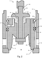
- Illustrated in Figure 3 is the trim assembly 11 with the plug 17 in an open throttling position.
- the stem assembly 43 is displaced upwardly and the nut 49 engages the bottom of the plug 17.
- the seal pressure acting on the high friction pressure energized seal 29 has been balanced thereby reducing or eliminating the contact of the high friction pressure energized seal 29 with the cage 13.
- the friction between the high friction pressurized seal 29 and the cage 13 is consequently reduced.
- the reduction in friction reduces the thrust required by the actuator 53 to displace the plug 17.
- the thrust provided by the actuator may be provided by mechanical, pneumatic, hydraulic or electrical means.
- Illustrated in Figure 4 is a method 101 of operating a trim assembly 11 in accordance with one embodiment.
- the method 101 is implemented by the trim assembly 11.
- step 103 the trim assembly 11 maintains a downstream pressure at a cage port 15 formed on a cage 13.
- step 105 the trim assembly 11 maintains an upstream pressure about a balanced plug 17 disposed in the cage 13, the balanced plug 17 being movable between a closed position, a pressure balancing position and an open position.
- step 107 the trim assembly 11 balances a seal pressure differential acting on a high friction pressure energized seal 29 disposed in a seal balancing volume 37 so that when the plug 17 is closed the pressure differential acting on the balance seal 29 is equal to the full pressure differential P1 - P2, and the pressure differential is minimized or removed when the plug 17 is in the pressure balancing or open position.
- This may be accomplished by pressurizing the seal balancing volume 37 to the upstream pressure.
- the plug 17 may be provided with an opening 24 at the top of the plug 17 and in fluid communication with the pressurizing volume 41. The opening 24 may be sealed by sealing flange 47 when the plug 17 is in the closed position.
- the opening 24 may be uncovered when the plug 17 is in the pressure balancing position.
- a sealing flange 47 is described as a means for sealing the opening 24, it would be apparent to one of ordinary skill in the art to provide other sealing members - for example a plug - without departing from the scope of the present invention.
Landscapes
- Engineering & Computer Science (AREA)
- General Engineering & Computer Science (AREA)
- Mechanical Engineering (AREA)
- Physics & Mathematics (AREA)
- Fluid Mechanics (AREA)
- General Physics & Mathematics (AREA)
- Automation & Control Theory (AREA)
- Sliding Valves (AREA)
- Multiple-Way Valves (AREA)
- Lift Valve (AREA)
- Fluid-Driven Valves (AREA)
Applications Claiming Priority (2)
| Application Number | Priority Date | Filing Date | Title |
|---|---|---|---|
| US13/681,795 US9218005B2 (en) | 2012-11-20 | 2012-11-20 | Apparatus and method for reducing actuator thrust requirements in a control valve |
| PCT/US2013/069789 WO2014081593A1 (en) | 2012-11-20 | 2013-11-13 | Apparatus and method for reducing actuator thrust requirements in a control valve |
Publications (2)
| Publication Number | Publication Date |
|---|---|
| EP2923126A1 EP2923126A1 (en) | 2015-09-30 |
| EP2923126B1 true EP2923126B1 (en) | 2021-01-20 |
Family
ID=49641894
Family Applications (1)
| Application Number | Title | Priority Date | Filing Date |
|---|---|---|---|
| EP13795673.6A Active EP2923126B1 (en) | 2012-11-20 | 2013-11-13 | Apparatus and method for reducing actuator thrust requirements in a control valve |
Country Status (7)
| Country | Link |
|---|---|
| US (1) | US9218005B2 (ja) |
| EP (1) | EP2923126B1 (ja) |
| JP (1) | JP6294892B2 (ja) |
| CN (1) | CN104956132B (ja) |
| CA (1) | CA2891590C (ja) |
| ES (1) | ES2864126T3 (ja) |
| WO (1) | WO2014081593A1 (ja) |
Families Citing this family (9)
| Publication number | Priority date | Publication date | Assignee | Title |
|---|---|---|---|---|
| US9218005B2 (en) * | 2012-11-20 | 2015-12-22 | Dresser, Inc. | Apparatus and method for reducing actuator thrust requirements in a control valve |
| US9395019B2 (en) | 2013-06-27 | 2016-07-19 | Dresser, Inc. | Device for sealing a valve |
| US9910447B2 (en) * | 2015-03-10 | 2018-03-06 | Fratelli Pettinaroli S.P.A. | Automatic balancing valve |
| KR101856545B1 (ko) * | 2016-06-08 | 2018-05-10 | 주식회사 오토마 | 이중 씰링 구조를 갖는 글로브 밸브 |
| US10400899B2 (en) * | 2017-07-24 | 2019-09-03 | Fisher Controls International, Llc | Fluid flow control apparatus for use with fluid valves |
| US10393283B2 (en) | 2017-09-25 | 2019-08-27 | Dresser, Llc | Regulating overtravel in bi-furcated plugs for use in valve assemblies |
| US10253887B1 (en) * | 2018-01-05 | 2019-04-09 | Circor International, Inc. | Stem assembly for a valve |
| US11713828B2 (en) * | 2019-04-30 | 2023-08-01 | Dresser, Llc | Pilot-operated pressure regulator |
| KR20220041916A (ko) * | 2019-08-05 | 2022-04-01 | 아이커 시스템즈, 인크. | 유량 제한기용 밀봉부 |
Family Cites Families (16)
| Publication number | Priority date | Publication date | Assignee | Title |
|---|---|---|---|---|
| US3114532A (en) * | 1960-08-12 | 1963-12-17 | Bendix Corp | Pilot type solenoid valve |
| US3318577A (en) * | 1965-05-24 | 1967-05-09 | George W Banks | High pressure valve having soft seating and balanced seal |
| US3624753A (en) | 1970-04-27 | 1971-11-30 | Grove Valve & Regulator Co | Two-stage opening valve |
| DE2915783C2 (de) | 1979-04-19 | 1986-07-03 | Vickers Systems GmbH, 6380 Bad Homburg | Aus Sicherheitsgründen arbeitsüberwachte Ventilanordnung |
| US4779837A (en) * | 1986-02-10 | 1988-10-25 | Tokyo Keiki Co., Ltd. | Remote control poppet valve |
| JPS62156686U (ja) * | 1986-03-26 | 1987-10-05 | ||
| US5339857A (en) * | 1992-11-06 | 1994-08-23 | Dresser Industries Inc. | Media assisted valves |
| US5263679A (en) * | 1993-03-10 | 1993-11-23 | Bushnell Engineering, Inc. | Valve with actuator |
| DE4330073A1 (de) * | 1993-09-06 | 1995-03-09 | Frutigen Hydrotechnik Ag | Vorgesteuertes Hydraulikventil |
| ES2125580T3 (es) | 1995-02-13 | 1999-03-01 | Cci Ag | Valvula accionada por el fluido controlado. |
| US5878647A (en) | 1997-08-11 | 1999-03-09 | Husco International Inc. | Pilot solenoid control valve and hydraulic control system using same |
| US6283152B1 (en) * | 1999-03-01 | 2001-09-04 | Cor-Val, Inc. | Multiple sleeve valve assembly |
| JP2003031455A (ja) * | 2001-07-19 | 2003-01-31 | Hitachi Kokusai Electric Inc | 基板処理装置 |
| EP1627170B1 (en) * | 2003-05-26 | 2006-11-08 | Danfoss A/S | A servo valve for a vacuum system |
| US7341236B2 (en) | 2006-03-07 | 2008-03-11 | Husco International, Inc. | Pilot operated valve with a pressure balanced poppet |
| US9218005B2 (en) * | 2012-11-20 | 2015-12-22 | Dresser, Inc. | Apparatus and method for reducing actuator thrust requirements in a control valve |
-
2012
- 2012-11-20 US US13/681,795 patent/US9218005B2/en active Active
-
2013
- 2013-11-13 WO PCT/US2013/069789 patent/WO2014081593A1/en active Application Filing
- 2013-11-13 JP JP2015542735A patent/JP6294892B2/ja active Active
- 2013-11-13 CA CA2891590A patent/CA2891590C/en active Active
- 2013-11-13 ES ES13795673T patent/ES2864126T3/es active Active
- 2013-11-13 EP EP13795673.6A patent/EP2923126B1/en active Active
- 2013-11-13 CN CN201380060624.6A patent/CN104956132B/zh active Active
Non-Patent Citations (1)
| Title |
|---|
| None * |
Also Published As
| Publication number | Publication date |
|---|---|
| JP2015535066A (ja) | 2015-12-07 |
| WO2014081593A1 (en) | 2014-05-30 |
| EP2923126A1 (en) | 2015-09-30 |
| CA2891590C (en) | 2021-01-12 |
| ES2864126T3 (es) | 2021-10-13 |
| US20140137947A1 (en) | 2014-05-22 |
| US9218005B2 (en) | 2015-12-22 |
| CA2891590A1 (en) | 2014-05-30 |
| JP6294892B2 (ja) | 2018-03-14 |
| CN104956132A (zh) | 2015-09-30 |
| CN104956132B (zh) | 2017-06-27 |
Similar Documents
| Publication | Publication Date | Title |
|---|---|---|
| EP2923126B1 (en) | Apparatus and method for reducing actuator thrust requirements in a control valve | |
| US9194501B2 (en) | Pressure balanced spring loaded overtravel sealing apparatus | |
| EP3569921A1 (en) | Poppet type pneumatic valve for inflation system | |
| US10054243B1 (en) | Dual spring flow control valve | |
| US20130037146A1 (en) | Fluid valves having multiple fluid flow control members | |
| CN111094818A (zh) | 阀门 | |
| WO2014209572A1 (en) | Device for sealing a valve | |
| US9989165B1 (en) | Dual mode flow control valve | |
| AU2010210501B2 (en) | Pressure-balanced control valves | |
| US9371936B2 (en) | Balanced globe valve assembly | |
| US20170370497A1 (en) | Valve assembly having a manual override unit | |
| JP6411738B2 (ja) | 圧力平衡ばね荷重オーバートラベル密閉装置 | |
| AU2017302032B2 (en) | Shutoff seal for high temperature pressure balance valve and related methods | |
| KR20200014812A (ko) | 액추에이터, 밸브, 유체 공급 시스템 및 반도체 제조 장치 | |
| RU2744981C1 (ru) | Двухседельный разгруженный клапан |
Legal Events
| Date | Code | Title | Description |
|---|---|---|---|
| PUAI | Public reference made under article 153(3) epc to a published international application that has entered the european phase |
Free format text: ORIGINAL CODE: 0009012 |
|
| 17P | Request for examination filed |
Effective date: 20150622 |
|
| AK | Designated contracting states |
Kind code of ref document: A1 Designated state(s): AL AT BE BG CH CY CZ DE DK EE ES FI FR GB GR HR HU IE IS IT LI LT LU LV MC MK MT NL NO PL PT RO RS SE SI SK SM TR |
|
| AX | Request for extension of the european patent |
Extension state: BA ME |
|
| DAX | Request for extension of the european patent (deleted) | ||
| STAA | Information on the status of an ep patent application or granted ep patent |
Free format text: STATUS: EXAMINATION IS IN PROGRESS |
|
| 17Q | First examination report despatched |
Effective date: 20170602 |
|
| GRAP | Despatch of communication of intention to grant a patent |
Free format text: ORIGINAL CODE: EPIDOSNIGR1 |
|
| STAA | Information on the status of an ep patent application or granted ep patent |
Free format text: STATUS: GRANT OF PATENT IS INTENDED |
|
| INTG | Intention to grant announced |
Effective date: 20200615 |
|
| GRAS | Grant fee paid |
Free format text: ORIGINAL CODE: EPIDOSNIGR3 |
|
| GRAA | (expected) grant |
Free format text: ORIGINAL CODE: 0009210 |
|
| STAA | Information on the status of an ep patent application or granted ep patent |
Free format text: STATUS: THE PATENT HAS BEEN GRANTED |
|
| RAP1 | Party data changed (applicant data changed or rights of an application transferred) |
Owner name: DRESSER, LLC |
|
| AK | Designated contracting states |
Kind code of ref document: B1 Designated state(s): AL AT BE BG CH CY CZ DE DK EE ES FI FR GB GR HR HU IE IS IT LI LT LU LV MC MK MT NL NO PL PT RO RS SE SI SK SM TR |
|
| REG | Reference to a national code |
Ref country code: GB Ref legal event code: FG4D |
|
| REG | Reference to a national code |
Ref country code: CH Ref legal event code: EP |
|
| REG | Reference to a national code |
Ref country code: AT Ref legal event code: REF Ref document number: 1356706 Country of ref document: AT Kind code of ref document: T Effective date: 20210215 |
|
| REG | Reference to a national code |
Ref country code: IE Ref legal event code: FG4D |
|
| REG | Reference to a national code |
Ref country code: DE Ref legal event code: R096 Ref document number: 602013075401 Country of ref document: DE |
|
| REG | Reference to a national code |
Ref country code: NL Ref legal event code: MP Effective date: 20210120 |
|
| REG | Reference to a national code |
Ref country code: LT Ref legal event code: MG9D |
|
| REG | Reference to a national code |
Ref country code: AT Ref legal event code: MK05 Ref document number: 1356706 Country of ref document: AT Kind code of ref document: T Effective date: 20210120 |
|
| PG25 | Lapsed in a contracting state [announced via postgrant information from national office to epo] |
Ref country code: BG Free format text: LAPSE BECAUSE OF FAILURE TO SUBMIT A TRANSLATION OF THE DESCRIPTION OR TO PAY THE FEE WITHIN THE PRESCRIBED TIME-LIMIT Effective date: 20210420 Ref country code: NL Free format text: LAPSE BECAUSE OF FAILURE TO SUBMIT A TRANSLATION OF THE DESCRIPTION OR TO PAY THE FEE WITHIN THE PRESCRIBED TIME-LIMIT Effective date: 20210120 Ref country code: NO Free format text: LAPSE BECAUSE OF FAILURE TO SUBMIT A TRANSLATION OF THE DESCRIPTION OR TO PAY THE FEE WITHIN THE PRESCRIBED TIME-LIMIT Effective date: 20210420 Ref country code: FI Free format text: LAPSE BECAUSE OF FAILURE TO SUBMIT A TRANSLATION OF THE DESCRIPTION OR TO PAY THE FEE WITHIN THE PRESCRIBED TIME-LIMIT Effective date: 20210120 Ref country code: GR Free format text: LAPSE BECAUSE OF FAILURE TO SUBMIT A TRANSLATION OF THE DESCRIPTION OR TO PAY THE FEE WITHIN THE PRESCRIBED TIME-LIMIT Effective date: 20210421 Ref country code: HR Free format text: LAPSE BECAUSE OF FAILURE TO SUBMIT A TRANSLATION OF THE DESCRIPTION OR TO PAY THE FEE WITHIN THE PRESCRIBED TIME-LIMIT Effective date: 20210120 Ref country code: PT Free format text: LAPSE BECAUSE OF FAILURE TO SUBMIT A TRANSLATION OF THE DESCRIPTION OR TO PAY THE FEE WITHIN THE PRESCRIBED TIME-LIMIT Effective date: 20210520 Ref country code: LT Free format text: LAPSE BECAUSE OF FAILURE TO SUBMIT A TRANSLATION OF THE DESCRIPTION OR TO PAY THE FEE WITHIN THE PRESCRIBED TIME-LIMIT Effective date: 20210120 |
|
| PG25 | Lapsed in a contracting state [announced via postgrant information from national office to epo] |
Ref country code: SE Free format text: LAPSE BECAUSE OF FAILURE TO SUBMIT A TRANSLATION OF THE DESCRIPTION OR TO PAY THE FEE WITHIN THE PRESCRIBED TIME-LIMIT Effective date: 20210120 Ref country code: RS Free format text: LAPSE BECAUSE OF FAILURE TO SUBMIT A TRANSLATION OF THE DESCRIPTION OR TO PAY THE FEE WITHIN THE PRESCRIBED TIME-LIMIT Effective date: 20210120 Ref country code: LV Free format text: LAPSE BECAUSE OF FAILURE TO SUBMIT A TRANSLATION OF THE DESCRIPTION OR TO PAY THE FEE WITHIN THE PRESCRIBED TIME-LIMIT Effective date: 20210120 Ref country code: PL Free format text: LAPSE BECAUSE OF FAILURE TO SUBMIT A TRANSLATION OF THE DESCRIPTION OR TO PAY THE FEE WITHIN THE PRESCRIBED TIME-LIMIT Effective date: 20210120 Ref country code: AT Free format text: LAPSE BECAUSE OF FAILURE TO SUBMIT A TRANSLATION OF THE DESCRIPTION OR TO PAY THE FEE WITHIN THE PRESCRIBED TIME-LIMIT Effective date: 20210120 |
|
| PG25 | Lapsed in a contracting state [announced via postgrant information from national office to epo] |
Ref country code: IS Free format text: LAPSE BECAUSE OF FAILURE TO SUBMIT A TRANSLATION OF THE DESCRIPTION OR TO PAY THE FEE WITHIN THE PRESCRIBED TIME-LIMIT Effective date: 20210520 |
|
| REG | Reference to a national code |
Ref country code: ES Ref legal event code: FG2A Ref document number: 2864126 Country of ref document: ES Kind code of ref document: T3 Effective date: 20211013 |
|
| REG | Reference to a national code |
Ref country code: DE Ref legal event code: R097 Ref document number: 602013075401 Country of ref document: DE |
|
| PG25 | Lapsed in a contracting state [announced via postgrant information from national office to epo] |
Ref country code: CZ Free format text: LAPSE BECAUSE OF FAILURE TO SUBMIT A TRANSLATION OF THE DESCRIPTION OR TO PAY THE FEE WITHIN THE PRESCRIBED TIME-LIMIT Effective date: 20210120 Ref country code: EE Free format text: LAPSE BECAUSE OF FAILURE TO SUBMIT A TRANSLATION OF THE DESCRIPTION OR TO PAY THE FEE WITHIN THE PRESCRIBED TIME-LIMIT Effective date: 20210120 Ref country code: SM Free format text: LAPSE BECAUSE OF FAILURE TO SUBMIT A TRANSLATION OF THE DESCRIPTION OR TO PAY THE FEE WITHIN THE PRESCRIBED TIME-LIMIT Effective date: 20210120 |
|
| PLBE | No opposition filed within time limit |
Free format text: ORIGINAL CODE: 0009261 |
|
| STAA | Information on the status of an ep patent application or granted ep patent |
Free format text: STATUS: NO OPPOSITION FILED WITHIN TIME LIMIT |
|
| PG25 | Lapsed in a contracting state [announced via postgrant information from national office to epo] |
Ref country code: RO Free format text: LAPSE BECAUSE OF FAILURE TO SUBMIT A TRANSLATION OF THE DESCRIPTION OR TO PAY THE FEE WITHIN THE PRESCRIBED TIME-LIMIT Effective date: 20210120 Ref country code: SK Free format text: LAPSE BECAUSE OF FAILURE TO SUBMIT A TRANSLATION OF THE DESCRIPTION OR TO PAY THE FEE WITHIN THE PRESCRIBED TIME-LIMIT Effective date: 20210120 Ref country code: DK Free format text: LAPSE BECAUSE OF FAILURE TO SUBMIT A TRANSLATION OF THE DESCRIPTION OR TO PAY THE FEE WITHIN THE PRESCRIBED TIME-LIMIT Effective date: 20210120 |
|
| 26N | No opposition filed |
Effective date: 20211021 |
|
| PG25 | Lapsed in a contracting state [announced via postgrant information from national office to epo] |
Ref country code: AL Free format text: LAPSE BECAUSE OF FAILURE TO SUBMIT A TRANSLATION OF THE DESCRIPTION OR TO PAY THE FEE WITHIN THE PRESCRIBED TIME-LIMIT Effective date: 20210120 |
|
| PG25 | Lapsed in a contracting state [announced via postgrant information from national office to epo] |
Ref country code: SI Free format text: LAPSE BECAUSE OF FAILURE TO SUBMIT A TRANSLATION OF THE DESCRIPTION OR TO PAY THE FEE WITHIN THE PRESCRIBED TIME-LIMIT Effective date: 20210120 |
|
| PG25 | Lapsed in a contracting state [announced via postgrant information from national office to epo] |
Ref country code: IS Free format text: LAPSE BECAUSE OF FAILURE TO SUBMIT A TRANSLATION OF THE DESCRIPTION OR TO PAY THE FEE WITHIN THE PRESCRIBED TIME-LIMIT Effective date: 20210520 |
|
| PG25 | Lapsed in a contracting state [announced via postgrant information from national office to epo] |
Ref country code: MC Free format text: LAPSE BECAUSE OF FAILURE TO SUBMIT A TRANSLATION OF THE DESCRIPTION OR TO PAY THE FEE WITHIN THE PRESCRIBED TIME-LIMIT Effective date: 20210120 |
|
| REG | Reference to a national code |
Ref country code: CH Ref legal event code: PL |
|
| PG25 | Lapsed in a contracting state [announced via postgrant information from national office to epo] |
Ref country code: LU Free format text: LAPSE BECAUSE OF NON-PAYMENT OF DUE FEES Effective date: 20211113 Ref country code: BE Free format text: LAPSE BECAUSE OF NON-PAYMENT OF DUE FEES Effective date: 20211130 |
|
| REG | Reference to a national code |
Ref country code: BE Ref legal event code: MM Effective date: 20211130 |
|
| PG25 | Lapsed in a contracting state [announced via postgrant information from national office to epo] |
Ref country code: IE Free format text: LAPSE BECAUSE OF NON-PAYMENT OF DUE FEES Effective date: 20211113 |
|
| PG25 | Lapsed in a contracting state [announced via postgrant information from national office to epo] |
Ref country code: HU Free format text: LAPSE BECAUSE OF FAILURE TO SUBMIT A TRANSLATION OF THE DESCRIPTION OR TO PAY THE FEE WITHIN THE PRESCRIBED TIME-LIMIT; INVALID AB INITIO Effective date: 20131113 |
|
| PG25 | Lapsed in a contracting state [announced via postgrant information from national office to epo] |
Ref country code: CY Free format text: LAPSE BECAUSE OF FAILURE TO SUBMIT A TRANSLATION OF THE DESCRIPTION OR TO PAY THE FEE WITHIN THE PRESCRIBED TIME-LIMIT Effective date: 20210120 |
|
| P01 | Opt-out of the competence of the unified patent court (upc) registered |
Effective date: 20230526 |
|
| PG25 | Lapsed in a contracting state [announced via postgrant information from national office to epo] |
Ref country code: LI Free format text: LAPSE BECAUSE OF NON-PAYMENT OF DUE FEES Effective date: 20220701 Ref country code: CH Free format text: LAPSE BECAUSE OF NON-PAYMENT OF DUE FEES Effective date: 20220701 |
|
| PGFP | Annual fee paid to national office [announced via postgrant information from national office to epo] |
Ref country code: GB Payment date: 20231019 Year of fee payment: 11 |
|
| PGFP | Annual fee paid to national office [announced via postgrant information from national office to epo] |
Ref country code: ES Payment date: 20231201 Year of fee payment: 11 |
|
| PGFP | Annual fee paid to national office [announced via postgrant information from national office to epo] |
Ref country code: IT Payment date: 20231019 Year of fee payment: 11 Ref country code: FR Payment date: 20231019 Year of fee payment: 11 Ref country code: DE Payment date: 20231019 Year of fee payment: 11 |
|
| PG25 | Lapsed in a contracting state [announced via postgrant information from national office to epo] |
Ref country code: MK Free format text: LAPSE BECAUSE OF FAILURE TO SUBMIT A TRANSLATION OF THE DESCRIPTION OR TO PAY THE FEE WITHIN THE PRESCRIBED TIME-LIMIT Effective date: 20210120 |