EP2922759B1 - Apparatus for applying a handle to a container and method thereof - Google Patents
Apparatus for applying a handle to a container and method thereof Download PDFInfo
- Publication number
- EP2922759B1 EP2922759B1 EP13856885.2A EP13856885A EP2922759B1 EP 2922759 B1 EP2922759 B1 EP 2922759B1 EP 13856885 A EP13856885 A EP 13856885A EP 2922759 B1 EP2922759 B1 EP 2922759B1
- Authority
- EP
- European Patent Office
- Prior art keywords
- handle
- container
- neck
- onto
- chuck
- Prior art date
- Legal status (The legal status is an assumption and is not a legal conclusion. Google has not performed a legal analysis and makes no representation as to the accuracy of the status listed.)
- Active
Links
Images









Classifications
-
- B—PERFORMING OPERATIONS; TRANSPORTING
- B65—CONVEYING; PACKING; STORING; HANDLING THIN OR FILAMENTARY MATERIAL
- B65D—CONTAINERS FOR STORAGE OR TRANSPORT OF ARTICLES OR MATERIALS, e.g. BAGS, BARRELS, BOTTLES, BOXES, CANS, CARTONS, CRATES, DRUMS, JARS, TANKS, HOPPERS, FORWARDING CONTAINERS; ACCESSORIES, CLOSURES, OR FITTINGS THEREFOR; PACKAGING ELEMENTS; PACKAGES
- B65D23/00—Details of bottles or jars not otherwise provided for
- B65D23/10—Handles
- B65D23/104—Handles formed separately
- B65D23/106—Handles formed separately the gripping region of the handle extending between the neck and the base of the bottle or jar and being located in a radial plane comprising the axis of the bottle or jar
-
- B—PERFORMING OPERATIONS; TRANSPORTING
- B65—CONVEYING; PACKING; STORING; HANDLING THIN OR FILAMENTARY MATERIAL
- B65B—MACHINES, APPARATUS OR DEVICES FOR, OR METHODS OF, PACKAGING ARTICLES OR MATERIALS; UNPACKING
- B65B61/00—Auxiliary devices, not otherwise provided for, for operating on sheets, blanks, webs, binding material, containers or packages
- B65B61/14—Auxiliary devices, not otherwise provided for, for operating on sheets, blanks, webs, binding material, containers or packages for incorporating, or forming and incorporating, handles or suspension means in packages
-
- B—PERFORMING OPERATIONS; TRANSPORTING
- B65—CONVEYING; PACKING; STORING; HANDLING THIN OR FILAMENTARY MATERIAL
- B65D—CONTAINERS FOR STORAGE OR TRANSPORT OF ARTICLES OR MATERIALS, e.g. BAGS, BARRELS, BOTTLES, BOXES, CANS, CARTONS, CRATES, DRUMS, JARS, TANKS, HOPPERS, FORWARDING CONTAINERS; ACCESSORIES, CLOSURES, OR FITTINGS THEREFOR; PACKAGING ELEMENTS; PACKAGES
- B65D1/00—Rigid or semi-rigid containers having bodies formed in one piece, e.g. by casting metallic material, by moulding plastics, by blowing vitreous material, by throwing ceramic material, by moulding pulped fibrous material or by deep-drawing operations performed on sheet material
- B65D1/02—Bottles or similar containers with necks or like restricted apertures, designed for pouring contents
- B65D1/0223—Bottles or similar containers with necks or like restricted apertures, designed for pouring contents characterised by shape
- B65D1/023—Neck construction
-
- B—PERFORMING OPERATIONS; TRANSPORTING
- B65—CONVEYING; PACKING; STORING; HANDLING THIN OR FILAMENTARY MATERIAL
- B65D—CONTAINERS FOR STORAGE OR TRANSPORT OF ARTICLES OR MATERIALS, e.g. BAGS, BARRELS, BOTTLES, BOXES, CANS, CARTONS, CRATES, DRUMS, JARS, TANKS, HOPPERS, FORWARDING CONTAINERS; ACCESSORIES, CLOSURES, OR FITTINGS THEREFOR; PACKAGING ELEMENTS; PACKAGES
- B65D1/00—Rigid or semi-rigid containers having bodies formed in one piece, e.g. by casting metallic material, by moulding plastics, by blowing vitreous material, by throwing ceramic material, by moulding pulped fibrous material or by deep-drawing operations performed on sheet material
- B65D1/02—Bottles or similar containers with necks or like restricted apertures, designed for pouring contents
- B65D1/0223—Bottles or similar containers with necks or like restricted apertures, designed for pouring contents characterised by shape
- B65D1/023—Neck construction
- B65D1/0246—Closure retaining means, e.g. beads, screw-threads
-
- B—PERFORMING OPERATIONS; TRANSPORTING
- B65—CONVEYING; PACKING; STORING; HANDLING THIN OR FILAMENTARY MATERIAL
- B65D—CONTAINERS FOR STORAGE OR TRANSPORT OF ARTICLES OR MATERIALS, e.g. BAGS, BARRELS, BOTTLES, BOXES, CANS, CARTONS, CRATES, DRUMS, JARS, TANKS, HOPPERS, FORWARDING CONTAINERS; ACCESSORIES, CLOSURES, OR FITTINGS THEREFOR; PACKAGING ELEMENTS; PACKAGES
- B65D23/00—Details of bottles or jars not otherwise provided for
- B65D23/10—Handles
- B65D23/104—Handles formed separately
- B65D23/108—Bail handles, i.e. pivoted handles of generally semi-circular or loop shape
Definitions
- the present invention relates to container handle. More specifically, the invention is directed to a handle configured to be applied to a container being lighter in weight than a conventional container.
- a handle to a container such as a bale handle
- the containers are typically stretch blown containers made of PET and an injection molded handle is typically applied to the container after molding. Such handles are typically applied to containers by simply being pressed over the threads of mouth of the container.
- ES 1 045 049 U describes a device to connect a handle to a carafe using a pulley and lateral disks.
- US 5,768,767 A describes a handle applicator for applying a handle having an attachment ring onto a neck of a container by expanding the ring as the ring is being applied.
- US 2005/0236356 A1 describes a method of making a container by providing a container having a neck, providing a container attachment having a circumferentially continuous ring, telescoping the ring over the neck, and radially expanding at least a portion of the neck to secure the attachment to the neck.
- consumers have become more environmentally aware and product suppliers are trying to meet their demands for less packaging materials.
- the industry is demanding more lighter weight containers.
- the lighter weight containers that are desired are not strong enough to resist the force required to apply the typical handle, and thus restricts how light a container can be made and still be strong enough to withstand the application force.
- the present invention was developed to improve the application of handles of the related art.
- the novel apparatus and method thereof explained herein differs from any previous apparatus and method because it applies a handle to the container using the mouth of the container as support.
- handles can be attached to light weight containers without having these containers collapse under the force of the application of these handles.
- a method for applying a handle to a container including placing the handle on a neck of the container, supporting the container to prevent the container from collapsing, and moving the handle toward an end of the neck that contacts a body of the container, wherein a supporting rib on the neck fixes the handle to the container.
- the moving the handle includes engaging a bead on the neck of the container with a support plate and pushing the handle toward the body of the container with a handle punch.
- the supporting the container may include having a neck guide rail engage a finish on the neck while the handle is placed on the neck of the container.
- the moving the handle may include engaging the handle with an application chuck and simultaneously rotating and moving the application chuck toward the container, wherein the application chuck screws the handle to the neck.
- compressed gas may be placed in the container before the moving the handle is performed.
- the moving the handle may include engaging threads on the neck of the container with a threaded application chuck and rotating the threaded application chuck onto the neck of the container.
- the rotating the threaded application chuck onto the neck of the container may push the handle toward the body of the container.
- an apparatus for applying a handle to a container including neck guide rail to support the container, a handle guide rail to move the handle into a position above a neck of the container, and a handle applicator for applying the handle onto the neck of the container.
- the handle applicator for applying the handle includes a plurality of support plates to support the container and a handle punch that pushes the handle onto the neck of the container.
- the plurality of support plates are configured to grasp the bead at the sealing end of the neck before the handle punch pushes the handle onto the neck of the container to support the container.
- the plurality of support plates includes at least one cutout.
- the handle applicator includes an application chuck that can rotate to apply the handle to the neck.
- the application chuck may include a member that contacts the handle to screw the handle to the neck.
- the handle applicator may include a threaded application chuck that interacts with threads on the neck of the container to apply the handle onto the neck of the container.
- a tube is releasably attached to a sealing surface of the neck.
- a method for supporting a neck of a container including placing a device in the neck and expanding the device diametrically to engage the neck.
- the engaging the neck may increase the rigidity of the neck.
- FIG. 1 is an exemplary embodiment of a container 1 having a container body 10, a handle 12, and a container cap 14.
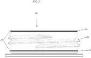
- an exemplary embodiment of the container 1 has a neck 20 having threads 26 and a finish 22, where the finish 22 extends along the diameter of the neck 20 without interfering with threads 26.
- the finish 22 has a bead 24 at the sealing surface of the neck 20.
- the bead 24 is molded at the sealing surface to increase the width of the seal surface and extend down the diameter of the finish 22, without interfering with the threads 26.
- a support ring 28 is molded along the diameter of the finish 22 at an end of the neck 20 opposite of the sealing surface, at a location just before the neck 20 meets the container body 10.
- the handle 12 shown in FIG. 3 has a circular portion 12a that can attach around the neck 20 of the container 1. There is also provided a handle member 12b on the handle 12.
- a method for applying a handle 12 to a container 1 is shown in FIG. 4 .
- the container 1 travels along a conveyor 40, as shown in FIG. 5 .
- the conveyor 40 may have conveyor guide rails 42 to prevent the container 1 from falling off the conveyor 40.
- the conveyor 40 may be a table-top conveyor, air conveyor, or the like.
- the container 1 approaches an outlet of the handle application machine 5 at step S2, where the handle 12 is oriented so that the circular portion 12a is in a forward position of the handle member 12b.
- the handle 12 is supported on the handle application machine 5 by handle guide rails 44.
- the handle 12 exits the handle application machine 5 at step S3, with circular portion 12a exiting first so that it sits on the neck 20.
- the handle application machine 5 is angled to allow the handle 12 to be pulled off handle application machine 5 when the circular portion 12a contacts the neck 20 of the container 1. It will be understood that the handle application machine 5 may be disposed at any angle, and can move the handle 12 along handle guide rails 44 using gravity or by a conveyor-belt-like system (not shown).
- neck guide rails 32 may engage the finish 22 of the container at step S4. This can occur either before or after the handle 12 is pulled off handle application machine 5. Neck guide rails 32 will engage the container 1 just below the support rib 28 of the finish 22 and provide support to the container 1 during positioning of the handle 12.
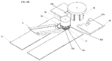
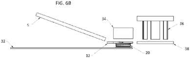
- the conveyor moves the container 1 forward until the container 1 is under the pre-positioning chuck 34, as shown in FIG. 6A and 6B .
- the pre-positioning chuck 34 presses the handle 12 approximately halfway down the finish 22.
- the neck guide rails 32 oppose the force exerted by the pre-positioning chuck 34, allowing light weight containers to have handles applied to them.
- the pre-positioning chuck 34 is but one way to position handle 12, and the handle 12 may be positioned using any method known in the art, including rollers or a ramp system.
- the conveyor 40 moves the container 1 forward, allowing the neck 20 to disengage from the neck engaging rails 32 at step S7.
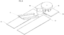
- the container 1 is positioned under the handle punch 36 where, as shown in FIG. 7 and step S8, support plates 38 clamp the finish 22 on the bead 24 formed at the sealing surface of the neck 12.
- the handle punch 36 is lowered through cutouts 39a, 39b on support plates 38 as shown in FIG. 8 .
- the handle punch 36 is lowered and contacts the handle 12, pushing the handle 12 over threads 26 and under support rib 28.
- the handle punch 36 is raised and the support plates 38 are removed from the bead 24 of the finish 22.
- the handle 12 may be applied to the container 1 by screwing the handle 12 onto the neck 20.
- threads 26 contain more thread turns than necessary for attaching container cap 14. As shown in FIG. 9 , the thread pitch of threads 26 decrease toward the end of neck 20, where neck 20 connects to container 1. Threads 26 form extended threads 26a, forming a support that is essentially horizontal, allowing the handle 12 to attach to the container 1 by inner tabs 12c.
- the handle 12 is applied to the neck 20 of container 1 as in steps S1-S7. Once the handle 12 is placed on the neck 20, the container 1 moves forward, disengaging neck 20 from the neck engaging guide rails 32, until container 1 is positioned under the application chuck 50. At step 8, the application chuck 50 is lowered and engages the handle 12, as shown in FIG.10A and 10B . The application chuck 50 is simultaneously rotated and lowered so that inner tabs 12c of the handle 12 engage the threads 26 of the container 1, allowing the handle 12 to be screwed onto the neck 20. The application chuck 50 rotates the handle 12, allowing inner tabs 12c and threads 26 to engage, until the handle 12 has been screwed to the neck 20. The inner tabs 12c engage with extended threads 26a, preventing the handle 12 from falling off and providing the support necessary for the container 1 to be lifted using handle 12.
- conveyor guide rails 42 prevent the container 1 from rotating.
- the invention is not limited to the conveyor guide rails 42 to prevent the container 1 from rotating during the described handle 12 application.
- the container 1 travels along the conveyor 40 and the handle 12 is placed on the neck 20 as described in the above exemplary embodiments and illustrated by steps S1-S7 of FIG. 4 .
- Neck guide rails 42 engage the container 1 under the finish 22 of the neck 20.
- the support plates 38 may grasp the bead 24.
- the handle punch 36 contains a hole in the center, as shown in FIG. 11 , through which a tube 60 may extend.
- the tube 60 contacts the sealing surface of the neck 20 and a compressed gas is released into the container 1.
- the compressed gas increases the pressure inside the container and provides more rigidity to the container 1.
- the handle punch 36 descends around the tube 60 and pushes the handle 12 into the proper position on the neck 20.
- the handle punch 36, support plates 34, and tube 60 are then removed from the container 1 and the compressed gas escapes.
- the support plates 38 may grasp the bead 24 before or after the tube 60 contacts the sealing surface of the neck 20, and the handle punch 36, support plates 38, and tube 60 may be removed from the container 1 in any order.
- the compressed gas may also be added to the container 1 when applying the handle 12 to the container 1 by using the application chuck 50.
- the tube 60 is lowered and contacts the sealing surface of the neck 20 after the handle 12 has been placed on the neck 20. Compressed gas is released into the container 1 through tube 60.
- the application chuck 50 is then simultaneously rotated and lowered, thereby screwing the handle 12 onto neck 20.
- the handle 12 may be applied to the container 1 by a threaded application chuck 52.
- the container 1 travels along a conveyor belt 40. Similar to the above-described embodiments, the handle 12 is placed on the neck 20 of the container 1. Neck guide rails 32 engage the container 1 under the finish 22 of the neck 20. The conveyor 40 move the container 1 forward so that pre-positioning rollers 54 can press down on the handle 12, as shown in FIG. 13 . This positioning allows handle 12 to be pushed onto the finish to allow threaded application chuck 52 to engage the container.
- the pre-positioning chuck 34 as shown in FIGS. 6A and 6B , can be used in place of the pre-positioning rollers 54.
- the container 1 is released from the neck guide rails 32.
- a threaded application chuck 52 descends and engages threads 26 of neck 20.
- the threaded application chuck 52 is screwed onto threads 26 of the neck 20, pushing the handle 12 toward container body 10 and over support rib 28.
- the conveyor guide rails 42 prevent the container 1 from rotating.
- the threaded application chuck 52 is unscrewed from the threads 26 of the neck 20 and the container 1.
- an expander 60 can help apply the handle to the neck 20.
- the container 1 may move along the conveyor 40 and have a handle 12 placed on the neck 20 of the container 1. Once this occurs, an expander 60 in an unexpanded state may be placed into the neck 20, as shown in FIG. 15 . Once the expander 60 is placed in the device, it may expand to engage the an inner wall of the neck 20, as shown in FIG. 16 .
- the neck 20 becomes more rigid and is may be supported by expander 60. At this point, the neck 20 is more rigid than the container body 10.
- the handle 12 may then be applied to the neck 20 of the container 1. Once the handle 12 is applied to the neck 20 of the container 1, the expander 60 can be brought back to an unexpanded state so that it no longer is engaging the neck 20. After expander 60 has disengaged the neck 20, the expander 60 may be removed from the neck 20.
- the container 1, handle 12, container cap 14, and neck 20 will be made of PET; however, these items are not limited to PET and can be made of any material known in the art.
- the container 1 is not limited to any size, but typical sizes are 7.938 kilograms (17.5 pounds) or 15.88 kilograms (35 pounds).
- the handle 12 can be made of PET; however, these items are not limited to PET and can be made of any material known in the art.
- the container 1 is not limited to any size, but typical sizes are 7.938 kilograms (17.5 pounds) or 15.88 kilograms (35 pounds).
- the handle 12 can be made of PET; however, these items are not limited to PET and can be made of any material known in the art.
- the container 1 is not limited to any size, but typical sizes are 7.938 kilograms (17.5 pounds) or 15.88 kilograms (35 pounds).
- the handle 12 can be made of PET; however, these items are not limited to PET and can be made of any material known in the art.
- the container 1 is not limited to any size, but typical sizes are 7.93
- embodiments of the invention are not limited thereto.
Landscapes
- Engineering & Computer Science (AREA)
- Mechanical Engineering (AREA)
- Ceramic Engineering (AREA)
- Details Of Rigid Or Semi-Rigid Containers (AREA)
Description
- The present invention relates to container handle. More specifically, the invention is directed to a handle configured to be applied to a container being lighter in weight than a conventional container.
- The general use of applying a handle to a container, such as a bale handle, is known in the art. The containers are typically stretch blown containers made of PET and an injection molded handle is typically applied to the container after molding. Such handles are typically applied to containers by simply being pressed over the threads of mouth of the container.
ES 1 045 049 UUS 5,768,767 A describes a handle applicator for applying a handle having an attachment ring onto a neck of a container by expanding the ring as the ring is being applied.US 2005/0236356 A1 describes a method of making a container by providing a container having a neck, providing a container attachment having a circumferentially continuous ring, telescoping the ring over the neck, and radially expanding at least a portion of the neck to secure the attachment to the neck.
In recent years, consumers have become more environmentally aware and product suppliers are trying to meet their demands for less packaging materials. With the increased cost of resins used to produce containers and the desire to decrease weight of the containers, the industry is demanding more lighter weight containers. However, the lighter weight containers that are desired are not strong enough to resist the force required to apply the typical handle, and thus restricts how light a container can be made and still be strong enough to withstand the application force. - Therefore, there is a need for a solution to place a handle on lighter weight containers.
- The present invention was developed to improve the application of handles of the related art. In particular, the novel apparatus and method thereof explained herein differs from any previous apparatus and method because it applies a handle to the container using the mouth of the container as support. Moreover, with the present invention, handles can be attached to light weight containers without having these containers collapse under the force of the application of these handles.
- According to an exemplary embodiment, there is provided a method for applying a handle to a container, including placing the handle on a neck of the container, supporting the container to prevent the container from collapsing, and moving the handle toward an end of the neck that contacts a body of the container, wherein a supporting rib on the neck fixes the handle to the container. The moving the handle includes engaging a bead on the neck of the container with a support plate and pushing the handle toward the body of the container with a handle punch.
- The supporting the container may include having a neck guide rail engage a finish on the neck while the handle is placed on the neck of the container.
- The moving the handle may include engaging the handle with an application chuck and simultaneously rotating and moving the application chuck toward the container, wherein the application chuck screws the handle to the neck.
- According to another aspect of an exemplary embodiment, compressed gas may be placed in the container before the moving the handle is performed.
- The moving the handle may include engaging threads on the neck of the container with a threaded application chuck and rotating the threaded application chuck onto the neck of the container.
- The rotating the threaded application chuck onto the neck of the container may push the handle toward the body of the container.
- According to another aspect of an exemplary embodiment, there is provided an apparatus for applying a handle to a container, including neck guide rail to support the container, a handle guide rail to move the handle into a position above a neck of the container, and a handle applicator for applying the handle onto the neck of the container.
- The handle applicator for applying the handle includes a plurality of support plates to support the container and a handle punch that pushes the handle onto the neck of the container.
- The plurality of support plates are configured to grasp the bead at the sealing end of the neck before the handle punch pushes the handle onto the neck of the container to support the container.
- In yet another exemplary embodiment, the plurality of support plates includes at least one cutout.
- In yet another exemplary embodiment, the handle applicator includes an application chuck that can rotate to apply the handle to the neck.
- The application chuck may include a member that contacts the handle to screw the handle to the neck.
- The handle applicator may include a threaded application chuck that interacts with threads on the neck of the container to apply the handle onto the neck of the container.
- In yet another exemplary embodiment, a tube is releasably attached to a sealing surface of the neck.
- According to another embodiment of the method of the invention, there is provided a method for supporting a neck of a container, including placing a device in the neck and expanding the device diametrically to engage the neck.
- The engaging the neck may increase the rigidity of the neck.
- The above and other objects, features, and advantages of the present invention will become more readily apparent from the following detailed description of exemplary embodiments of the invention, taken in conjunction with the accompanying drawings, in which:
-
FIG. 1 is a 3-D view of a finished container; -
FIG. 2 is a side view of a neck showing threads on the neck; -
FIG. 3 is a top view showing a handle being placed on a neck of a container; -
FIG. 4 is a block diagram showing an exemplary embodiment of applying a handle to a container; -
FIG. 5 is a side view showing a handle being placed on a neck of a container; -
FIG. 6A is a top view showing a pre-positioning chuck aligning a handle on a container; -
FIG. 6B is a side view showing a pre-positioning chuck aligning a handle on a container; -
FIG. 7 is a top view showing support plates grasping a neck of a container; -
FIG. 8 is a top view showing a handle punch pushing a handle onto a neck of a container; -
FIG. 9 is a side view showing an exemplary embodiment of an apparatus to screw a handle onto a neck of a container; -
FIG. 10A is a top view of showing an application chuck screwing a handle onto a neck of a container; -
FIG. 10B is a side view of showing an application chuck screwing a handle onto a neck of a container; -
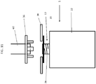
FIG. 11 is a side view of an exemplary embodiment of an apparatus that can push a handle onto a neck of a container with a tube that can pump a compressed gas into the container; -
FIG. 12 is a side view of an exemplary embodiment of an apparatus that can screw a handle onto a neck of a container with a tube that can pump a compressed gas into the container; -
FIG. 13 is a side view showing an exemplary embodiment of aligning a handle on a neck of a container; -
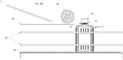
FIG. 14 is a side view showing a threaded application chuck screwing pushing a handle onto a neck of a container; -
FIG. 15 is a side view showing an expandable device being placed in a neck of a container; and -
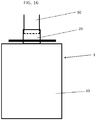
FIG. 16 is a side view showing an expandable device expanded in a neck of a container and a handle on the neck of the container. - Exemplary embodiments will now be described more fully with reference to the accompanying drawings. The exemplary embodiments, however, may be embodied in many different forms and should not be construed as being limited to the embodiments set forth herein; rather, these exemplary embodiments are provided so that this disclosure will be thorough and complete, and will fully convey the concept of the disclosure to those skilled in the art. In the drawings, the size of the various components may be exaggerated for clarity. Like reference numerals in the drawings denote like elements, and thus their description will be omitted.
-
FIG. 1 is an exemplary embodiment of acontainer 1 having acontainer body 10, ahandle 12, and a container cap 14. - As shown in
FIG. 2 , an exemplary embodiment of thecontainer 1 has aneck 20 havingthreads 26 and afinish 22, where thefinish 22 extends along the diameter of theneck 20 without interfering withthreads 26. Thefinish 22 has abead 24 at the sealing surface of theneck 20. Thebead 24 is molded at the sealing surface to increase the width of the seal surface and extend down the diameter of thefinish 22, without interfering with thethreads 26. In addition, asupport ring 28 is molded along the diameter of thefinish 22 at an end of theneck 20 opposite of the sealing surface, at a location just before theneck 20 meets thecontainer body 10. - The
handle 12, shown inFIG. 3 , has acircular portion 12a that can attach around theneck 20 of thecontainer 1. There is also provided ahandle member 12b on thehandle 12. - In one exemplary embodiment, a method for applying a
handle 12 to acontainer 1 is shown inFIG. 4 . At step S1, thecontainer 1 travels along aconveyor 40, as shown inFIG. 5 . Theconveyor 40 may haveconveyor guide rails 42 to prevent thecontainer 1 from falling off theconveyor 40. Theconveyor 40 may be a table-top conveyor, air conveyor, or the like. - The
container 1 approaches an outlet of thehandle application machine 5 at step S2, where thehandle 12 is oriented so that thecircular portion 12a is in a forward position of thehandle member 12b. Thehandle 12 is supported on thehandle application machine 5 by handle guide rails 44. As shown inFIG. 3 , thehandle 12 exits thehandle application machine 5 at step S3, withcircular portion 12a exiting first so that it sits on theneck 20. Thehandle application machine 5 is angled to allow thehandle 12 to be pulled offhandle application machine 5 when thecircular portion 12a contacts theneck 20 of thecontainer 1. It will be understood that thehandle application machine 5 may be disposed at any angle, and can move thehandle 12 alonghandle guide rails 44 using gravity or by a conveyor-belt-like system (not shown). - As shown in
FIG. 3 , neck guide rails 32 may engage thefinish 22 of the container at step S4. This can occur either before or after thehandle 12 is pulled offhandle application machine 5. Neck guide rails 32 will engage thecontainer 1 just below thesupport rib 28 of thefinish 22 and provide support to thecontainer 1 during positioning of thehandle 12. - At step S5, the conveyor moves the
container 1 forward until thecontainer 1 is under thepre-positioning chuck 34, as shown inFIG. 6A and6B . At step S6, thepre-positioning chuck 34 presses thehandle 12 approximately halfway down thefinish 22. The neck guide rails 32 oppose the force exerted by thepre-positioning chuck 34, allowing light weight containers to have handles applied to them. It will be understood that thepre-positioning chuck 34 is but one way to positionhandle 12, and thehandle 12 may be positioned using any method known in the art, including rollers or a ramp system. - Once the positioning of the
handle 12 has been accomplished, theconveyor 40 moves thecontainer 1 forward, allowing theneck 20 to disengage from theneck engaging rails 32 at step S7. Thecontainer 1 is positioned under thehandle punch 36 where, as shown inFIG. 7 and step S8,support plates 38 clamp thefinish 22 on thebead 24 formed at the sealing surface of theneck 12. Once thebead 24 has been clamped, thehandle punch 36 is lowered throughcutouts support plates 38 as shown inFIG. 8 . Thehandle punch 36 is lowered and contacts thehandle 12, pushing thehandle 12 overthreads 26 and undersupport rib 28. Once thehandle 12 is secured undersupport ring 28, thehandle punch 36 is raised and thesupport plates 38 are removed from thebead 24 of thefinish 22. - In yet another embodiment, the
handle 12 may be applied to thecontainer 1 by screwing thehandle 12 onto theneck 20. In this exemplary embodiment,threads 26 contain more thread turns than necessary for attaching container cap 14. As shown inFIG. 9 , the thread pitch ofthreads 26 decrease toward the end ofneck 20, whereneck 20 connects tocontainer 1.Threads 26 form extendedthreads 26a, forming a support that is essentially horizontal, allowing thehandle 12 to attach to thecontainer 1 by inner tabs 12c. - The
handle 12 is applied to theneck 20 ofcontainer 1 as in steps S1-S7. Once thehandle 12 is placed on theneck 20, thecontainer 1 moves forward, disengagingneck 20 from the neck engagingguide rails 32, untilcontainer 1 is positioned under theapplication chuck 50. At step 8, theapplication chuck 50 is lowered and engages thehandle 12, as shown inFIG.10A and10B . Theapplication chuck 50 is simultaneously rotated and lowered so that inner tabs 12c of thehandle 12 engage thethreads 26 of thecontainer 1, allowing thehandle 12 to be screwed onto theneck 20. Theapplication chuck 50 rotates thehandle 12, allowing inner tabs 12c andthreads 26 to engage, until thehandle 12 has been screwed to theneck 20. The inner tabs 12c engage withextended threads 26a, preventing thehandle 12 from falling off and providing the support necessary for thecontainer 1 to be lifted usinghandle 12. - During the simultaneous rotation and lowering of the
application chuck 50 to twist thehandle 12 onto thefinish 22,conveyor guide rails 42 prevent thecontainer 1 from rotating. However, it will be understood that the invention is not limited to theconveyor guide rails 42 to prevent thecontainer 1 from rotating during the describedhandle 12 application. - In another exemplary embodiment, the
container 1 travels along theconveyor 40 and thehandle 12 is placed on theneck 20 as described in the above exemplary embodiments and illustrated by steps S1-S7 ofFIG. 4 .Neck guide rails 42 engage thecontainer 1 under thefinish 22 of theneck 20. After thehandle 12 has been aligned, thesupport plates 38 may grasp thebead 24. In this exemplary embodiment, thehandle punch 36 contains a hole in the center, as shown inFIG. 11 , through which atube 60 may extend. - The
tube 60 contacts the sealing surface of theneck 20 and a compressed gas is released into thecontainer 1. The compressed gas increases the pressure inside the container and provides more rigidity to thecontainer 1. Once the compressed gas is added, thehandle punch 36 descends around thetube 60 and pushes thehandle 12 into the proper position on theneck 20. Thehandle punch 36,support plates 34, andtube 60 are then removed from thecontainer 1 and the compressed gas escapes. Thesupport plates 38 may grasp thebead 24 before or after thetube 60 contacts the sealing surface of theneck 20, and thehandle punch 36,support plates 38, andtube 60 may be removed from thecontainer 1 in any order. - As shown in
FIG. 12 , the compressed gas may also be added to thecontainer 1 when applying thehandle 12 to thecontainer 1 by using theapplication chuck 50. Thetube 60 is lowered and contacts the sealing surface of theneck 20 after thehandle 12 has been placed on theneck 20. Compressed gas is released into thecontainer 1 throughtube 60. Theapplication chuck 50 is then simultaneously rotated and lowered, thereby screwing thehandle 12 ontoneck 20. - In yet another embodiment, the
handle 12 may be applied to thecontainer 1 by a threadedapplication chuck 52. As shown inFIG. 5 , thecontainer 1 travels along aconveyor belt 40. Similar to the above-described embodiments, thehandle 12 is placed on theneck 20 of thecontainer 1.Neck guide rails 32 engage thecontainer 1 under thefinish 22 of theneck 20. Theconveyor 40 move thecontainer 1 forward so thatpre-positioning rollers 54 can press down on thehandle 12, as shown inFIG. 13 . This positioning allows handle 12 to be pushed onto the finish to allow threadedapplication chuck 52 to engage the container. In will be understood that thepre-positioning chuck 34, as shown inFIGS. 6A and6B , can be used in place of thepre-positioning rollers 54. - Once the
handle 12 has been properly positioned by pre-positioningrollers 54, thecontainer 1 is released from the neck guide rails 32. As shown inFIG. 14 , a threadedapplication chuck 52 descends and engagesthreads 26 ofneck 20. The threadedapplication chuck 52 is screwed ontothreads 26 of theneck 20, pushing thehandle 12 towardcontainer body 10 and oversupport rib 28. During the application of thehandle 12, theconveyor guide rails 42 prevent thecontainer 1 from rotating. Once thehandle 12 is moved over thesupport rib 28, the threadedapplication chuck 52 is unscrewed from thethreads 26 of theneck 20 and thecontainer 1. - In yet another exemplary example, an
expander 60 can help apply the handle to theneck 20. As discussed in other exemplary embodiments, thecontainer 1 may move along theconveyor 40 and have ahandle 12 placed on theneck 20 of thecontainer 1. Once this occurs, anexpander 60 in an unexpanded state may be placed into theneck 20, as shown inFIG. 15 . Once theexpander 60 is placed in the device, it may expand to engage the an inner wall of theneck 20, as shown inFIG. 16 . - When the
expander 60 engages the inner wall of theneck 20, theneck 20 becomes more rigid and is may be supported byexpander 60. At this point, theneck 20 is more rigid than thecontainer body 10. Thehandle 12 may then be applied to theneck 20 of thecontainer 1. Once thehandle 12 is applied to theneck 20 of thecontainer 1, theexpander 60 can be brought back to an unexpanded state so that it no longer is engaging theneck 20. Afterexpander 60 has disengaged theneck 20, theexpander 60 may be removed from theneck 20. - In one exemplary embodiment, the
container 1, handle 12, container cap 14, andneck 20 will be made of PET; however, these items are not limited to PET and can be made of any material known in the art. Thecontainer 1 is not limited to any size, but typical sizes are 7.938 kilograms (17.5 pounds) or 15.88 kilograms (35 pounds). Thehandle 12 can - be injected molded and the
container 1 can be stretch blown. However, embodiments of the invention are not limited thereto.
Claims (15)
- A method for applying a handle (12) to a container (1), comprising:placing the handle (12) on a neck (20) of the container (1);supporting the container (1) to prevent the container (1) from collapsing; andmoving the handle (12) toward an end of the neck (20) that contacts a body (10) of the container (1),wherein a supporting rib (28) on the neck (20) fixes the handle (12) to the container (1), characterised in that the moving the handle (12) includes engaging a bead (24) on the neck (20) of the container (1) with a support plate (38) and pushing the handle (12) toward the body (10) of the container (1) with a handle punch (36).
- The method of claim 1, wherein the supporting the container (1) includes having a neck guide rail (32) engage a finish on the neck (20) while the handle (12) is placed on the neck (20) of the container (1).
- The method of claim 1, wherein the moving the handle (12) includes engaging the handle (12) with an application chuck (50) and simultaneously rotating and moving the application chuck (50) toward the container (1), wherein the application chuck (50) screws the handle (12) to the neck (20).
- The method of claims 1 or 3, further comprising placing a compressed gas the container (1) before the moving the handle (12) is performed.
- The method of claim 1, wherein the moving the handle (12) includes engaging threads (26) on the neck (20) of the container (1) with a threaded application chuck (50) and rotating the threaded application chuck (50) onto the neck (20) of the container (1).
- The method of claim 5, wherein the rotating the threaded application chuck (50) onto the neck (20) of the container (1) pushes the handle (12) toward the body (10) of the container (1).
- The method of anyone of the preceding claims, comprising, for supporting the neck (20) of the container (1):placing a device in the neck (20);expanding the device diametrically to engage the neck (20).
- The method of claim 7, wherein the engaging the neck (20) increases the rigidity of the neck (20).
- An apparatus for applying a handle (12) to a container (1), comprising:a neck guide rail (32) to support the container (1);a handle guide rail (44) to move the handle (12) into a position above a neck (20) of the container (1); anda handle applicator for applying the handle (12) onto the neck (20) of the container (1); characterised in that the handle applicator for applying the handle (12) includes a plurality of support plates (38) to support the container (1), and a handle punch (36) that pushes the handle (12) onto the neck (20) of the container (1).
- The apparatus of claim 9, wherein the plurality of support plates (38) are configured to grasp a bead (24) at the sealing end of the neck (20) before the handle punch (36) pushes the handle (12) onto the neck (20) of the container (1) to support the container (1).
- The apparatus of claim 9, wherein the plurality of support plates (38) includes at least one cutout (39a, 39b).
- The apparatus of claim 9, wherein the handle applicator includes an application chuck (50) that can rotate to apply the handle (12) to the neck (20).
- The apparatus of claim 12, wherein the application chuck (50) includes a member that contacts the handle (12) to screw the handle (12) to the neck (20).
- The apparatus of claim 9, wherein the handle applicator includes a threaded application chuck (50) that interacts with threads (26) on the neck (20) of the container (1) to apply the handle (12) onto the neck (20) of the container (1).
- The apparatus of claim 9, further comprising a tube (60) that is releasably attached to a sealing surface of the neck (20).
Applications Claiming Priority (2)
| Application Number | Priority Date | Filing Date | Title |
|---|---|---|---|
| US201261728547P | 2012-11-20 | 2012-11-20 | |
| PCT/US2013/070875 WO2014081750A1 (en) | 2012-11-20 | 2013-11-20 | Apparatus for applying a handle to a container and method thereof |
Publications (3)
| Publication Number | Publication Date |
|---|---|
| EP2922759A1 EP2922759A1 (en) | 2015-09-30 |
| EP2922759A4 EP2922759A4 (en) | 2016-07-13 |
| EP2922759B1 true EP2922759B1 (en) | 2018-03-21 |
Family
ID=50776502
Family Applications (1)
| Application Number | Title | Priority Date | Filing Date |
|---|---|---|---|
| EP13856885.2A Active EP2922759B1 (en) | 2012-11-20 | 2013-11-20 | Apparatus for applying a handle to a container and method thereof |
Country Status (4)
| Country | Link |
|---|---|
| US (1) | US9994361B2 (en) |
| EP (1) | EP2922759B1 (en) |
| CA (1) | CA2887267C (en) |
| WO (1) | WO2014081750A1 (en) |
Families Citing this family (11)
| Publication number | Priority date | Publication date | Assignee | Title |
|---|---|---|---|---|
| WO2014081750A1 (en) * | 2012-11-20 | 2014-05-30 | Carl Ring | Apparatus for applying a handle to a container and method thereof |
| ES2777998B2 (en) * | 2019-02-06 | 2021-01-13 | And & Or Res S L U | MACHINE FOR PLACING HANDLES IN CONTAINERS |
| USD1047689S1 (en) * | 2021-10-07 | 2024-10-22 | Deb Ip Limited | Container |
| USD1103771S1 (en) | 2022-09-09 | 2025-12-02 | Cargill, Incorporated | Container |
| USD1067769S1 (en) | 2022-09-09 | 2025-03-25 | Cargill, Incorporated | Integrated dual container system |
| USD1073463S1 (en) | 2022-09-09 | 2025-05-06 | Wayzata | Integrated dual container system |
| USD1102901S1 (en) | 2022-09-09 | 2025-11-25 | Cargill, Incorporated | Container |
| USD1067768S1 (en) | 2022-09-09 | 2025-03-25 | Cargill, Incorporated | Integrated dual container system |
| USD1101570S1 (en) | 2022-09-09 | 2025-11-11 | Cargill, Incorporated | Container |
| USD1067770S1 (en) | 2022-09-09 | 2025-03-25 | Cargill, Incorporated | Integrated dual container system |
| USD1103772S1 (en) | 2022-09-09 | 2025-12-02 | Cargill, Incorporated | Container |
Citations (2)
| Publication number | Priority date | Publication date | Assignee | Title |
|---|---|---|---|---|
| US3690141A (en) * | 1969-07-18 | 1972-09-12 | Dale Ltd John | Taper-expanding mandrel |
| US3780492A (en) * | 1971-02-05 | 1973-12-25 | A C I Operations | Apparatus for packing bottles, jars or like into cases |
Family Cites Families (19)
| Publication number | Priority date | Publication date | Assignee | Title |
|---|---|---|---|---|
| US3036371A (en) * | 1960-01-06 | 1962-05-29 | Gray Homer | Press for applying handle to containers |
| US3987535A (en) * | 1975-07-31 | 1976-10-26 | Brown Winton F | Bottle decapping method and apparatus |
| US4236305A (en) * | 1978-04-26 | 1980-12-02 | Abbott Laboratories | Apparatus for fitting a resilient ring on a bottle |
| US4939890A (en) | 1989-04-14 | 1990-07-10 | Fci, Inc. | Anti-rotation method and apparatus for bottle capping machines |
| US5259912A (en) * | 1992-04-16 | 1993-11-09 | Spear, Incorporated | Continuous in-line labeler for flexible bottles |
| US5768767A (en) | 1996-09-23 | 1998-06-23 | Schmalbach-Lubeca Ag | Automatic handle applicator |
| US6082078A (en) * | 1999-02-19 | 2000-07-04 | R & B Machine Tool Company | Nutrunner driver for a plastic bottle capping machine |
| ES1045049Y (en) | 1999-12-28 | 2000-12-16 | Goixart Antonio Berne | DEVICE FOR THE COUPLING OF HANDLES ON TABLETS AND THE LIKE. |
| US6977104B1 (en) * | 2003-03-28 | 2005-12-20 | Graham Packaging Pet Technologies Inc. | Container preform assembly and method of manufacture |
| US7028857B2 (en) * | 2003-05-28 | 2006-04-18 | Fci, Inc. | Plastic water bottle and apparatus and method to convey the bottle and prevent bottle rotation |
| US20050236356A1 (en) | 2004-04-21 | 2005-10-27 | Lonsway Michael J | Plastic container and method of integrally securing a neck attachment thereto |
| US20070272651A1 (en) | 2006-05-25 | 2007-11-29 | Graham Packaging Company, L.P. | Handle attachment for a container |
| GB2452055A (en) | 2007-08-22 | 2009-02-25 | Flexifill Ltd | Aseptic container filling |
| US20110305545A1 (en) * | 2010-06-10 | 2011-12-15 | Craig Steven Davis | System and Method for High-Volume Filling of Pharmaceutical Prescriptions |
| FR2968637B1 (en) * | 2010-12-08 | 2012-12-21 | Tecma Pack | METHOD AND DEVICE FOR COLLAPPING TO REALIZE A SEQUENTIAL COLLECTION OF LOTS OF PRODUCTS WITHIN PACKAGING RECEPTACLES. |
| WO2014081750A1 (en) * | 2012-11-20 | 2014-05-30 | Carl Ring | Apparatus for applying a handle to a container and method thereof |
| US9573771B2 (en) * | 2015-06-09 | 2017-02-21 | The Procter & Gamble Company | Systems, apparatus, and methods for grouping articles into arrays of various configurations |
| US9540127B2 (en) * | 2015-06-09 | 2017-01-10 | The Procter & Gamble Company | Drive mechanism and methods of grouping articles |
| US9663305B2 (en) * | 2015-06-09 | 2017-05-30 | The Procter & Gamble Company | Method of grouping articles into arrays of various configurations |
-
2013
- 2013-11-20 WO PCT/US2013/070875 patent/WO2014081750A1/en not_active Ceased
- 2013-11-20 US US14/438,964 patent/US9994361B2/en active Active
- 2013-11-20 EP EP13856885.2A patent/EP2922759B1/en active Active
- 2013-11-20 CA CA2887267A patent/CA2887267C/en active Active
Patent Citations (2)
| Publication number | Priority date | Publication date | Assignee | Title |
|---|---|---|---|---|
| US3690141A (en) * | 1969-07-18 | 1972-09-12 | Dale Ltd John | Taper-expanding mandrel |
| US3780492A (en) * | 1971-02-05 | 1973-12-25 | A C I Operations | Apparatus for packing bottles, jars or like into cases |
Also Published As
| Publication number | Publication date |
|---|---|
| US9994361B2 (en) | 2018-06-12 |
| US20150291310A1 (en) | 2015-10-15 |
| EP2922759A1 (en) | 2015-09-30 |
| CA2887267C (en) | 2019-02-12 |
| CA2887267A1 (en) | 2014-05-30 |
| EP2922759A4 (en) | 2016-07-13 |
| WO2014081750A1 (en) | 2014-05-30 |
Similar Documents
| Publication | Publication Date | Title |
|---|---|---|
| CA2887267C (en) | Apparatus for applying a handle to a container and method thereof | |
| US10273051B2 (en) | Container and handle system | |
| US11565867B2 (en) | Method of handling a plastic container having a moveable base | |
| WO2011062891A1 (en) | Pressurized capping apparatus | |
| ITMO20100295A1 (en) | TANK MACHINE | |
| CN104443608B (en) | Machines for treating containers and method | |
| US20230166897A1 (en) | Method of handling a plastic container having a moveable base | |
| CZ305551B6 (en) | Apparatus for reducing the diameter of open end of a container and method of reducing carried out using the apparatus | |
| KR20170141727A (en) | Method and apparatus for curling an article | |
| CN106624739A (en) | Automatic assembly machine for multi-level parts of motor rotor shaft | |
| CN207013479U (en) | A kind of unwinding device for automatic stamping equipment | |
| JP7322215B2 (en) | Mandrel for printing necked cans | |
| CA2920378C (en) | Bail handle applicator | |
| US3911074A (en) | Method of making thin-walled plastic screw caps | |
| US9364938B2 (en) | Apparatus for holding a container | |
| CN108349664A (en) | For orienting opening and shutting beverage container and applying the device and method of label in precalculated position | |
| US8191340B1 (en) | Mandrel brake arrangement for a web supply in a packaging machine | |
| US4015325A (en) | Method and apparatus for securing inserts to containers | |
| JPH03184643A (en) | Machine for forming bead on cylindrical can body | |
| CN109071057A (en) | The label of perforated is oriented and grabbed by rotational motion | |
| KR101277410B1 (en) | Device for the selective and progressive locking of metal containers | |
| KR102587070B1 (en) | Method and apparatus for can expansion | |
| CN205366411U (en) | Fragile article protection safety packing box | |
| SK500552009A3 (en) | Method for attachment the balloon, especially by impessing, equipment for attachment of the balloon | |
| US2731071A (en) | Method of securing gaskets in container closures |
Legal Events
| Date | Code | Title | Description |
|---|---|---|---|
| PUAI | Public reference made under article 153(3) epc to a published international application that has entered the european phase |
Free format text: ORIGINAL CODE: 0009012 |
|
| 17P | Request for examination filed |
Effective date: 20150521 |
|
| AK | Designated contracting states |
Kind code of ref document: A1 Designated state(s): AL AT BE BG CH CY CZ DE DK EE ES FI FR GB GR HR HU IE IS IT LI LT LU LV MC MK MT NL NO PL PT RO RS SE SI SK SM TR |
|
| AX | Request for extension of the european patent |
Extension state: BA ME |
|
| DAX | Request for extension of the european patent (deleted) | ||
| RA4 | Supplementary search report drawn up and despatched (corrected) |
Effective date: 20160609 |
|
| RIC1 | Information provided on ipc code assigned before grant |
Ipc: B65D 1/02 20060101ALI20160603BHEP Ipc: B65D 23/10 20060101ALI20160603BHEP Ipc: B65B 61/14 20060101AFI20160603BHEP |
|
| STAA | Information on the status of an ep patent application or granted ep patent |
Free format text: STATUS: EXAMINATION IS IN PROGRESS |
|
| 17Q | First examination report despatched |
Effective date: 20170310 |
|
| GRAP | Despatch of communication of intention to grant a patent |
Free format text: ORIGINAL CODE: EPIDOSNIGR1 |
|
| STAA | Information on the status of an ep patent application or granted ep patent |
Free format text: STATUS: GRANT OF PATENT IS INTENDED |
|
| INTG | Intention to grant announced |
Effective date: 20171019 |
|
| GRAS | Grant fee paid |
Free format text: ORIGINAL CODE: EPIDOSNIGR3 |
|
| GRAA | (expected) grant |
Free format text: ORIGINAL CODE: 0009210 |
|
| STAA | Information on the status of an ep patent application or granted ep patent |
Free format text: STATUS: THE PATENT HAS BEEN GRANTED |
|
| AK | Designated contracting states |
Kind code of ref document: B1 Designated state(s): AL AT BE BG CH CY CZ DE DK EE ES FI FR GB GR HR HU IE IS IT LI LT LU LV MC MK MT NL NO PL PT RO RS SE SI SK SM TR |
|
| REG | Reference to a national code |
Ref country code: GB Ref legal event code: FG4D |
|
| REG | Reference to a national code |
Ref country code: CH Ref legal event code: EP |
|
| REG | Reference to a national code |
Ref country code: AT Ref legal event code: REF Ref document number: 980815 Country of ref document: AT Kind code of ref document: T Effective date: 20180415 |
|
| REG | Reference to a national code |
Ref country code: IE Ref legal event code: FG4D |
|
| REG | Reference to a national code |
Ref country code: DE Ref legal event code: R096 Ref document number: 602013034873 Country of ref document: DE |
|
| REG | Reference to a national code |
Ref country code: NL Ref legal event code: FP |
|
| PG25 | Lapsed in a contracting state [announced via postgrant information from national office to epo] |
Ref country code: NO Free format text: LAPSE BECAUSE OF FAILURE TO SUBMIT A TRANSLATION OF THE DESCRIPTION OR TO PAY THE FEE WITHIN THE PRESCRIBED TIME-LIMIT Effective date: 20180621 Ref country code: HR Free format text: LAPSE BECAUSE OF FAILURE TO SUBMIT A TRANSLATION OF THE DESCRIPTION OR TO PAY THE FEE WITHIN THE PRESCRIBED TIME-LIMIT Effective date: 20180321 Ref country code: LT Free format text: LAPSE BECAUSE OF FAILURE TO SUBMIT A TRANSLATION OF THE DESCRIPTION OR TO PAY THE FEE WITHIN THE PRESCRIBED TIME-LIMIT Effective date: 20180321 Ref country code: CY Free format text: LAPSE BECAUSE OF FAILURE TO SUBMIT A TRANSLATION OF THE DESCRIPTION OR TO PAY THE FEE WITHIN THE PRESCRIBED TIME-LIMIT Effective date: 20180321 |
|
| REG | Reference to a national code |
Ref country code: LT Ref legal event code: MG4D |
|
| REG | Reference to a national code |
Ref country code: AT Ref legal event code: MK05 Ref document number: 980815 Country of ref document: AT Kind code of ref document: T Effective date: 20180321 |
|
| PG25 | Lapsed in a contracting state [announced via postgrant information from national office to epo] |
Ref country code: LV Free format text: LAPSE BECAUSE OF FAILURE TO SUBMIT A TRANSLATION OF THE DESCRIPTION OR TO PAY THE FEE WITHIN THE PRESCRIBED TIME-LIMIT Effective date: 20180321 Ref country code: SE Free format text: LAPSE BECAUSE OF FAILURE TO SUBMIT A TRANSLATION OF THE DESCRIPTION OR TO PAY THE FEE WITHIN THE PRESCRIBED TIME-LIMIT Effective date: 20180321 Ref country code: GR Free format text: LAPSE BECAUSE OF FAILURE TO SUBMIT A TRANSLATION OF THE DESCRIPTION OR TO PAY THE FEE WITHIN THE PRESCRIBED TIME-LIMIT Effective date: 20180622 Ref country code: RS Free format text: LAPSE BECAUSE OF FAILURE TO SUBMIT A TRANSLATION OF THE DESCRIPTION OR TO PAY THE FEE WITHIN THE PRESCRIBED TIME-LIMIT Effective date: 20180321 Ref country code: BG Free format text: LAPSE BECAUSE OF FAILURE TO SUBMIT A TRANSLATION OF THE DESCRIPTION OR TO PAY THE FEE WITHIN THE PRESCRIBED TIME-LIMIT Effective date: 20180621 |
|
| PG25 | Lapsed in a contracting state [announced via postgrant information from national office to epo] |
Ref country code: RO Free format text: LAPSE BECAUSE OF FAILURE TO SUBMIT A TRANSLATION OF THE DESCRIPTION OR TO PAY THE FEE WITHIN THE PRESCRIBED TIME-LIMIT Effective date: 20180321 Ref country code: IT Free format text: LAPSE BECAUSE OF FAILURE TO SUBMIT A TRANSLATION OF THE DESCRIPTION OR TO PAY THE FEE WITHIN THE PRESCRIBED TIME-LIMIT Effective date: 20180321 Ref country code: EE Free format text: LAPSE BECAUSE OF FAILURE TO SUBMIT A TRANSLATION OF THE DESCRIPTION OR TO PAY THE FEE WITHIN THE PRESCRIBED TIME-LIMIT Effective date: 20180321 Ref country code: AL Free format text: LAPSE BECAUSE OF FAILURE TO SUBMIT A TRANSLATION OF THE DESCRIPTION OR TO PAY THE FEE WITHIN THE PRESCRIBED TIME-LIMIT Effective date: 20180321 Ref country code: PL Free format text: LAPSE BECAUSE OF FAILURE TO SUBMIT A TRANSLATION OF THE DESCRIPTION OR TO PAY THE FEE WITHIN THE PRESCRIBED TIME-LIMIT Effective date: 20180321 Ref country code: ES Free format text: LAPSE BECAUSE OF FAILURE TO SUBMIT A TRANSLATION OF THE DESCRIPTION OR TO PAY THE FEE WITHIN THE PRESCRIBED TIME-LIMIT Effective date: 20180321 |
|
| PG25 | Lapsed in a contracting state [announced via postgrant information from national office to epo] |
Ref country code: AT Free format text: LAPSE BECAUSE OF FAILURE TO SUBMIT A TRANSLATION OF THE DESCRIPTION OR TO PAY THE FEE WITHIN THE PRESCRIBED TIME-LIMIT Effective date: 20180321 Ref country code: CZ Free format text: LAPSE BECAUSE OF FAILURE TO SUBMIT A TRANSLATION OF THE DESCRIPTION OR TO PAY THE FEE WITHIN THE PRESCRIBED TIME-LIMIT Effective date: 20180321 Ref country code: SK Free format text: LAPSE BECAUSE OF FAILURE TO SUBMIT A TRANSLATION OF THE DESCRIPTION OR TO PAY THE FEE WITHIN THE PRESCRIBED TIME-LIMIT Effective date: 20180321 Ref country code: SM Free format text: LAPSE BECAUSE OF FAILURE TO SUBMIT A TRANSLATION OF THE DESCRIPTION OR TO PAY THE FEE WITHIN THE PRESCRIBED TIME-LIMIT Effective date: 20180321 |
|
| PG25 | Lapsed in a contracting state [announced via postgrant information from national office to epo] |
Ref country code: PT Free format text: LAPSE BECAUSE OF FAILURE TO SUBMIT A TRANSLATION OF THE DESCRIPTION OR TO PAY THE FEE WITHIN THE PRESCRIBED TIME-LIMIT Effective date: 20180723 |
|
| REG | Reference to a national code |
Ref country code: DE Ref legal event code: R097 Ref document number: 602013034873 Country of ref document: DE |
|
| PLBE | No opposition filed within time limit |
Free format text: ORIGINAL CODE: 0009261 |
|
| STAA | Information on the status of an ep patent application or granted ep patent |
Free format text: STATUS: NO OPPOSITION FILED WITHIN TIME LIMIT |
|
| PG25 | Lapsed in a contracting state [announced via postgrant information from national office to epo] |
Ref country code: DK Free format text: LAPSE BECAUSE OF FAILURE TO SUBMIT A TRANSLATION OF THE DESCRIPTION OR TO PAY THE FEE WITHIN THE PRESCRIBED TIME-LIMIT Effective date: 20180321 |
|
| 26N | No opposition filed |
Effective date: 20190102 |
|
| PG25 | Lapsed in a contracting state [announced via postgrant information from national office to epo] |
Ref country code: SI Free format text: LAPSE BECAUSE OF FAILURE TO SUBMIT A TRANSLATION OF THE DESCRIPTION OR TO PAY THE FEE WITHIN THE PRESCRIBED TIME-LIMIT Effective date: 20180321 |
|
| REG | Reference to a national code |
Ref country code: CH Ref legal event code: PL |
|
| PG25 | Lapsed in a contracting state [announced via postgrant information from national office to epo] |
Ref country code: LU Free format text: LAPSE BECAUSE OF NON-PAYMENT OF DUE FEES Effective date: 20181120 Ref country code: MC Free format text: LAPSE BECAUSE OF FAILURE TO SUBMIT A TRANSLATION OF THE DESCRIPTION OR TO PAY THE FEE WITHIN THE PRESCRIBED TIME-LIMIT Effective date: 20180321 |
|
| REG | Reference to a national code |
Ref country code: BE Ref legal event code: MM Effective date: 20181130 |
|
| PG25 | Lapsed in a contracting state [announced via postgrant information from national office to epo] |
Ref country code: CH Free format text: LAPSE BECAUSE OF NON-PAYMENT OF DUE FEES Effective date: 20181130 Ref country code: LI Free format text: LAPSE BECAUSE OF NON-PAYMENT OF DUE FEES Effective date: 20181130 |
|
| PG25 | Lapsed in a contracting state [announced via postgrant information from national office to epo] |
Ref country code: BE Free format text: LAPSE BECAUSE OF NON-PAYMENT OF DUE FEES Effective date: 20181130 |
|
| PG25 | Lapsed in a contracting state [announced via postgrant information from national office to epo] |
Ref country code: MT Free format text: LAPSE BECAUSE OF NON-PAYMENT OF DUE FEES Effective date: 20181120 |
|
| PG25 | Lapsed in a contracting state [announced via postgrant information from national office to epo] |
Ref country code: TR Free format text: LAPSE BECAUSE OF FAILURE TO SUBMIT A TRANSLATION OF THE DESCRIPTION OR TO PAY THE FEE WITHIN THE PRESCRIBED TIME-LIMIT Effective date: 20180321 |
|
| PG25 | Lapsed in a contracting state [announced via postgrant information from national office to epo] |
Ref country code: MK Free format text: LAPSE BECAUSE OF NON-PAYMENT OF DUE FEES Effective date: 20180321 Ref country code: HU Free format text: LAPSE BECAUSE OF FAILURE TO SUBMIT A TRANSLATION OF THE DESCRIPTION OR TO PAY THE FEE WITHIN THE PRESCRIBED TIME-LIMIT; INVALID AB INITIO Effective date: 20131120 |
|
| PG25 | Lapsed in a contracting state [announced via postgrant information from national office to epo] |
Ref country code: IS Free format text: LAPSE BECAUSE OF FAILURE TO SUBMIT A TRANSLATION OF THE DESCRIPTION OR TO PAY THE FEE WITHIN THE PRESCRIBED TIME-LIMIT Effective date: 20180721 |
|
| PGFP | Annual fee paid to national office [announced via postgrant information from national office to epo] |
Ref country code: NL Payment date: 20251027 Year of fee payment: 13 |
|
| PGFP | Annual fee paid to national office [announced via postgrant information from national office to epo] |
Ref country code: DE Payment date: 20251024 Year of fee payment: 13 |
|
| PGFP | Annual fee paid to national office [announced via postgrant information from national office to epo] |
Ref country code: GB Payment date: 20251024 Year of fee payment: 13 |
|
| PGFP | Annual fee paid to national office [announced via postgrant information from national office to epo] |
Ref country code: FI Payment date: 20251028 Year of fee payment: 13 |
|
| PGFP | Annual fee paid to national office [announced via postgrant information from national office to epo] |
Ref country code: FR Payment date: 20251024 Year of fee payment: 13 |
|
| PGFP | Annual fee paid to national office [announced via postgrant information from national office to epo] |
Ref country code: IE Payment date: 20251024 Year of fee payment: 13 |