EP2922517B1 - Apparatus for training dynamic balance and turning manoeuvres during walking - Google Patents
Apparatus for training dynamic balance and turning manoeuvres during walking Download PDFInfo
- Publication number
- EP2922517B1 EP2922517B1 EP13821534.8A EP13821534A EP2922517B1 EP 2922517 B1 EP2922517 B1 EP 2922517B1 EP 13821534 A EP13821534 A EP 13821534A EP 2922517 B1 EP2922517 B1 EP 2922517B1
- Authority
- EP
- European Patent Office
- Prior art keywords
- joints
- freedom
- side connection
- pelvis
- rotation
- Prior art date
- Legal status (The legal status is an assumption and is not a legal conclusion. Google has not performed a legal analysis and makes no representation as to the accuracy of the status listed.)
- Not-in-force
Links
Images










Classifications
-
- A—HUMAN NECESSITIES
- A61—MEDICAL OR VETERINARY SCIENCE; HYGIENE
- A61H—PHYSICAL THERAPY APPARATUS, e.g. DEVICES FOR LOCATING OR STIMULATING REFLEX POINTS IN THE BODY; ARTIFICIAL RESPIRATION; MASSAGE; BATHING DEVICES FOR SPECIAL THERAPEUTIC OR HYGIENIC PURPOSES OR SPECIFIC PARTS OF THE BODY
- A61H3/00—Appliances for aiding patients or disabled persons to walk about
- A61H3/008—Appliances for aiding patients or disabled persons to walk about using suspension devices for supporting the body in an upright walking or standing position, e.g. harnesses
-
- A—HUMAN NECESSITIES
- A61—MEDICAL OR VETERINARY SCIENCE; HYGIENE
- A61H—PHYSICAL THERAPY APPARATUS, e.g. DEVICES FOR LOCATING OR STIMULATING REFLEX POINTS IN THE BODY; ARTIFICIAL RESPIRATION; MASSAGE; BATHING DEVICES FOR SPECIAL THERAPEUTIC OR HYGIENIC PURPOSES OR SPECIFIC PARTS OF THE BODY
- A61H3/00—Appliances for aiding patients or disabled persons to walk about
- A61H3/04—Wheeled walking aids for patients or disabled persons
-
- A—HUMAN NECESSITIES
- A63—SPORTS; GAMES; AMUSEMENTS
- A63B—APPARATUS FOR PHYSICAL TRAINING, GYMNASTICS, SWIMMING, CLIMBING, OR FENCING; BALL GAMES; TRAINING EQUIPMENT
- A63B21/00—Exercising apparatus for developing or strengthening the muscles or joints of the body by working against a counterforce, with or without measuring devices
- A63B21/40—Interfaces with the user related to strength training; Details thereof
- A63B21/4001—Arrangements for attaching the exercising apparatus to the user's body, e.g. belts, shoes or gloves specially adapted therefor
- A63B21/4009—Arrangements for attaching the exercising apparatus to the user's body, e.g. belts, shoes or gloves specially adapted therefor to the waist
-
- A—HUMAN NECESSITIES
- A63—SPORTS; GAMES; AMUSEMENTS
- A63B—APPARATUS FOR PHYSICAL TRAINING, GYMNASTICS, SWIMMING, CLIMBING, OR FENCING; BALL GAMES; TRAINING EQUIPMENT
- A63B22/00—Exercising apparatus specially adapted for conditioning the cardio-vascular system, for training agility or co-ordination of movements
- A63B22/02—Exercising apparatus specially adapted for conditioning the cardio-vascular system, for training agility or co-ordination of movements with movable endless bands, e.g. treadmills
-
- A—HUMAN NECESSITIES
- A63—SPORTS; GAMES; AMUSEMENTS
- A63B—APPARATUS FOR PHYSICAL TRAINING, GYMNASTICS, SWIMMING, CLIMBING, OR FENCING; BALL GAMES; TRAINING EQUIPMENT
- A63B22/00—Exercising apparatus specially adapted for conditioning the cardio-vascular system, for training agility or co-ordination of movements
- A63B22/14—Platforms for reciprocating rotating motion about a vertical axis, e.g. axis through the middle of the platform
-
- A—HUMAN NECESSITIES
- A63—SPORTS; GAMES; AMUSEMENTS
- A63B—APPARATUS FOR PHYSICAL TRAINING, GYMNASTICS, SWIMMING, CLIMBING, OR FENCING; BALL GAMES; TRAINING EQUIPMENT
- A63B26/00—Exercising apparatus not covered by groups A63B1/00 - A63B25/00
- A63B26/003—Exercising apparatus not covered by groups A63B1/00 - A63B25/00 for improving balance or equilibrium
-
- A—HUMAN NECESSITIES
- A63—SPORTS; GAMES; AMUSEMENTS
- A63B—APPARATUS FOR PHYSICAL TRAINING, GYMNASTICS, SWIMMING, CLIMBING, OR FENCING; BALL GAMES; TRAINING EQUIPMENT
- A63B69/00—Training appliances or apparatus for special sports
- A63B69/0064—Attachments on the trainee preventing falling
-
- A—HUMAN NECESSITIES
- A61—MEDICAL OR VETERINARY SCIENCE; HYGIENE
- A61H—PHYSICAL THERAPY APPARATUS, e.g. DEVICES FOR LOCATING OR STIMULATING REFLEX POINTS IN THE BODY; ARTIFICIAL RESPIRATION; MASSAGE; BATHING DEVICES FOR SPECIAL THERAPEUTIC OR HYGIENIC PURPOSES OR SPECIFIC PARTS OF THE BODY
- A61H2201/00—Characteristics of apparatus not provided for in the preceding codes
- A61H2201/12—Driving means
- A61H2201/1207—Driving means with electric or magnetic drive
-
- A—HUMAN NECESSITIES
- A61—MEDICAL OR VETERINARY SCIENCE; HYGIENE
- A61H—PHYSICAL THERAPY APPARATUS, e.g. DEVICES FOR LOCATING OR STIMULATING REFLEX POINTS IN THE BODY; ARTIFICIAL RESPIRATION; MASSAGE; BATHING DEVICES FOR SPECIAL THERAPEUTIC OR HYGIENIC PURPOSES OR SPECIFIC PARTS OF THE BODY
- A61H2201/00—Characteristics of apparatus not provided for in the preceding codes
- A61H2201/12—Driving means
- A61H2201/1207—Driving means with electric or magnetic drive
- A61H2201/1215—Rotary drive
-
- A—HUMAN NECESSITIES
- A61—MEDICAL OR VETERINARY SCIENCE; HYGIENE
- A61H—PHYSICAL THERAPY APPARATUS, e.g. DEVICES FOR LOCATING OR STIMULATING REFLEX POINTS IN THE BODY; ARTIFICIAL RESPIRATION; MASSAGE; BATHING DEVICES FOR SPECIAL THERAPEUTIC OR HYGIENIC PURPOSES OR SPECIFIC PARTS OF THE BODY
- A61H2201/00—Characteristics of apparatus not provided for in the preceding codes
- A61H2201/16—Physical interface with patient
- A61H2201/1602—Physical interface with patient kind of interface, e.g. head rest, knee support or lumbar support
- A61H2201/1628—Pelvis
- A61H2201/163—Pelvis holding means therefor
-
- A—HUMAN NECESSITIES
- A63—SPORTS; GAMES; AMUSEMENTS
- A63B—APPARATUS FOR PHYSICAL TRAINING, GYMNASTICS, SWIMMING, CLIMBING, OR FENCING; BALL GAMES; TRAINING EQUIPMENT
- A63B22/00—Exercising apparatus specially adapted for conditioning the cardio-vascular system, for training agility or co-ordination of movements
- A63B2022/0092—Exercising apparatus specially adapted for conditioning the cardio-vascular system, for training agility or co-ordination of movements for training agility or co-ordination of movements
-
- A—HUMAN NECESSITIES
- A63—SPORTS; GAMES; AMUSEMENTS
- A63B—APPARATUS FOR PHYSICAL TRAINING, GYMNASTICS, SWIMMING, CLIMBING, OR FENCING; BALL GAMES; TRAINING EQUIPMENT
- A63B22/00—Exercising apparatus specially adapted for conditioning the cardio-vascular system, for training agility or co-ordination of movements
- A63B2022/0094—Exercising apparatus specially adapted for conditioning the cardio-vascular system, for training agility or co-ordination of movements for active rehabilitation, e.g. slow motion devices
Definitions
- the object of the invention is an apparatus for training dynamic balance and turning manoeuvres during walking.
- the apparatus of the invention is suited for individuals in training dynamic balance and various turning manoeuvres while standing, while walking on a flat surface or while walking on a treadmill that can rotate around its vertical axis.
- the invention belongs to class A 63B 26/00 of the European Patent Classification.
- the technical problem successfully solved by the apparatus of the present invention is to provide such an aid that would allow suitable and especially safe dynamic balance training and consequently coordinated motion of the entire body especially of elderly and disabled individuals.
- An important part of functional abilities to walk comprises manoeuvres such as initiation and acceleration, stopping and deceleration, changing direction while walking and turning, turning on the spot and backward walking.
- electromechanical devices e. g. LOKOMAT, Gait Trainer
- US patent No. 7,086,996 An apparatus, in which the movement of the pelvis is provided for in directions left/right and forward/backwards while an individual is standing is disclosed in US patent No. 7,086,996 .
- the main constructional feature of said apparatus resides in two mechanical assemblies comprising a vertical spring, the effective length of which can be changed in a simple way thus setting the extent of a mechanical bracing of the pelvis belt.
- the apparatus has two degrees of freedom: it provides for a body inclination while standing on the spot forward and backwards and left and right. It does not provide for rotation of the body around a vertical axis, which is of key importance when changing a walking direction.
- the described prior art does not disclose an apparatus that would allow dynamic balance training in conditions, in which the pelvis and the body are adequately supported and yet coordinated motion of the entire body could be trained, which is needed in performing the above-mentioned manoeuvres.
- the described training is currently only possible by assistance of at least two physiotherapists.
- the invention relates to an apparatus for training dynamic balance and turning manoeuvres during walking as claimed in claim 1.
- the apparatus of the invention consists of a parallel mechanism, where universal joints are arranged in a base platform, said joints being connected via spherical (ball-in-socket) joints with a pelvis element in the first embodiment with two vertical rods and in the second embodiment with two vertical telescopic rods, said universal joints having two degrees of freedom that may be provided with a drive.
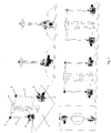
- Figure 1 is a schematic demonstration of a lower body part of a standing subject who is supported in the pelvis area by the apparatus of the invention according to the first embodiment; the apparatus allows training of dynamic balance and turning manoeuvres.
- the apparatus of the invention is represented by a parallel mechanism comprising: a base platform 1, on which first-type joints 2,2' are arranged, said joints being connected with a pelvis element 5 by two vertical rods 3,3' via spherical (ball-in-socket) joints 4,4'.
- Each first-type joint 2,2 has two degrees of freedom, wherein one degree of freedom of the first-type joint 2 is provided with a drive 6, whereas both degrees of freedom of the first-type joint 2' are provided with drives 7,8.
- the drives 6,7,8 are active servo drives, but can also be replaced by passive viscoelastic elements with variable impedance features.
- the base platform 1 can be a simple panel, a motorised mobile platform or a motorised platform with a treadmill arranged, wherein the motorised platform can rotate around the vertical axis as will be described hereinbelow.
- the apparatus for training dynamic balance and turning manoeuvres during walking has a total of four degrees of freedom with respect to the described components. Three degrees of freedom are motorised (provided with a drive) and one is passive as shown in Figure 2 to 9 .
- Figure 2 and 3 show inclination of the standing subject forward and backwards in a sagittal plane. Inclination forward and backwards can be assisted or guided (in terms of either positional servo guiding or impedance guiding) by the motor drives 6 and 7.
- Figures 4 and 5 show inclination of a standing subject to the left and right in a frontal plane. Inclination to the left and right is assisted or guided (in terms of either positional servo guiding or impedance guiding) by the drive 8.
- Figures 6 and 7 show a key degree of freedom of the proposed apparatus of the invention, namely rotation of the pelvis of a standing subject around a vertical axis in the transversal plane in clockwise direction as well as in counterclockwise direction.
- the described rotation of the standing subject's pelvis can be assisted or guided (in terms of either positional servo guiding or impedance guiding) by adequate operation of the drives 6 and 7.
- Motion in all three described degrees of freedom (inclination forward/backwards, inclination left/right and rotation in transversal plane) can be simultaneous and can be adequately assisted by adequate operation of the drives 6, 7 and 8.
- Figures 8 and 9 show a fourth degree of freedom of the proposed apparatus, i. e. passive tilt of the standing subject's pelvis forward and backwards in the sagittal plane. This degree of freedom is controlled by the standing subject.
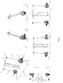
- each first-type joint 2,2' can be replaced by a vertical spring 20, one end of which is fastened to the base platform 1 and the other end is fastened to a vertical rod 3,3',30,30'.
- the entire mechanism is passive and exhibits mechanical impedance which is exerted on an individual's pelvis in the form of viscoelastic forces.
- each first-type joint 2,2' can be replaced by two simple rotational joints 20',20" each having only one axis of rotation, and the first simple joint 20' is fixed to the base platform 1, whereas the second simple joint 20" is fixed to the axis of the first simple joint 20' in a way that the axes of rotation of both simple joints 20', 20" are perpendicular, yet do not intersect at the same point.
- the vertical rods 3,3' which have a defined, unadjustable length can be replaced by vertically adjustable rods 30,30' which can contain a translational joint that allows length adjustment of the rods 30,30' and each of them can be embodied as a telescopic assembly of two rods and also balanced, for instance with a spring or a similar constructional element that compensates for the weight of the pelvis element 5.
- a further adjustment option is also possible by a constructional variant where the upper end of the rods 3,3',30,30' is slidably through-connected with the spherical joints 4,4', which is shown in Figure 11 .
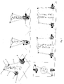
- the apparatus of the invention in the second embodiment thus provides for two new degrees of freedom: bias of the pelvis downwards/upwards in the frontal plane and a vertical shift of the pelvis downwards/upwards in all variants shown in Figures 1 to 9 ; a possibility of use of the vertically adjustable telescopic rods 30,30' is specifically shown in Figures 14 and 15 .
- the base platform 1 is a motorised mobile platform, it allows training of dynamic balance and turning manoeuvres during walking on the ground.
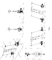
- a sequence of images in Figure 12 first shows walking in one direction, then follows a curve needed for an adequate change of direction during walking, which can be achieved in two ways.
- the walking subject initiates a manoeuvre of turning to a new direction by adequately rotating the pelvis, which is followed by an adequate rotation of the mobile platform and the adequate movement of the apparatus.
- the apparatus initiates rotation of the pelvis, which is followed by an adequate rotation of the mobile platform.
- the walking subject has a possibility of training of dynamic balance and turning manoeuvres assisted by motorised degrees of freedom that suit his/her current abilities.
- the base platform 1 is a motorised platform with a treadmill that can rotate around the vertical axis, it allows training of dynamic balance and turning manoeuvres during walking on the treadmill.
- a sequence of images in Figure 13 shows a turning manoeuvre that is principally identical to the turning manoeuvre shown in Figure 12 , a difference being in that here the mobile platform cannot freely move in a space but is limited to the rotation about the fixed axis of rotation.
- the base platform 1 is a motorised mobile platform according to the second embodiment shown in Figure 14 , it allows in addition to the already disclosed possibilities of manoeuvring with the apparatus of the invention accordng to the first embodiment, as described and shown in Figure 13 , also rotating of the pelvis upwards/downwards in the frontal plane and the vertical shift of the pelvis upwards/downwards.
- the base platform 1 is a motorised platform with a treadmill according to the second embodiment of Figure 15 that can rotate around the vertical axis, it allows training of dynamic balance and turning manoeuvres during walking on the treadmill.
- a sequence of images in Figure 15 shows a turning manoeuvre that is principally identical to the turning manoeuvre shown in Figure 14 , a difference being in that the mobile platform in this case is not limited only to rotation around the fixed axis of rotation but the axis of rotation can be anywhere, also for instance in the centre of the conveyor belt.
- the inventive aspect of the proposed apparatus for training of dynamic balance and turning manoeuvres during walking of the invention resides especially in a unique kinematic structure that enables the subject to train dynamic balance and rotation around the vertical body axis by a simultaneous motion of the lower body segments in the sagittal and frontal planes while standing, walking on the ground and walking on the treadmill that can rotate around the vertical axis.
- the motion of the proposed apparatus of the invention is from the biomechanical and physiological aspects in consistence with the motion of a human locomotor apparatus.
Landscapes
- Health & Medical Sciences (AREA)
- General Health & Medical Sciences (AREA)
- Physical Education & Sports Medicine (AREA)
- Life Sciences & Earth Sciences (AREA)
- Animal Behavior & Ethology (AREA)
- Rehabilitation Therapy (AREA)
- Pain & Pain Management (AREA)
- Epidemiology (AREA)
- Public Health (AREA)
- Veterinary Medicine (AREA)
- Cardiology (AREA)
- Vascular Medicine (AREA)
- Biophysics (AREA)
- Orthopedic Medicine & Surgery (AREA)
- Rehabilitation Tools (AREA)
Description
- The object of the invention is an apparatus for training dynamic balance and turning manoeuvres during walking. The apparatus of the invention is suited for individuals in training dynamic balance and various turning manoeuvres while standing, while walking on a flat surface or while walking on a treadmill that can rotate around its vertical axis. The invention belongs to class A 63B 26/00 of the European Patent Classification.
- The technical problem successfully solved by the apparatus of the present invention is to provide such an aid that would allow suitable and especially safe dynamic balance training and consequently coordinated motion of the entire body especially of elderly and disabled individuals.
- A variety of neurological disorders, as well as aging, result in a reduced ability to walk, which increases the odds of the disabled and also elderly population to fall. Apart from reduced muscular strength, inadequate sensory-motor coordination of motion and reduced abilities to turn or manoeuvre pose the main obstacle to functional walking. The mentioned abilities need to be maintained or re-trained, wherein it is important that training is done in a safe way and should include dynamic balance training. An important part of functional abilities to walk comprises manoeuvres such as initiation and acceleration, stopping and deceleration, changing direction while walking and turning, turning on the spot and backward walking. Currently, there are numerous electromechanical devices (e. g. LOKOMAT, Gait Trainer) that support walking either on a treadmill or on the floor and simultaneously offer a partial weight relief; however, said devices only provide for walking in one direction and what's more important the mobility of the pelvis and the body is considerably limited.
- An apparatus, in which the movement of the pelvis is provided for in directions left/right and forward/backwards while an individual is standing is disclosed in
US patent No. 7,086,996 . The main constructional feature of said apparatus resides in two mechanical assemblies comprising a vertical spring, the effective length of which can be changed in a simple way thus setting the extent of a mechanical bracing of the pelvis belt. The apparatus has two degrees of freedom: it provides for a body inclination while standing on the spot forward and backwards and left and right. It does not provide for rotation of the body around a vertical axis, which is of key importance when changing a walking direction. - The described prior art does not disclose an apparatus that would allow dynamic balance training in conditions, in which the pelvis and the body are adequately supported and yet coordinated motion of the entire body could be trained, which is needed in performing the above-mentioned manoeuvres. The described training is currently only possible by assistance of at least two physiotherapists.
- Document
US-A-2003/0181299 describes a balance training apparatus for supporting users with reduced ability to maintain balance. - The invention relates to an apparatus for training dynamic balance and turning manoeuvres during walking as claimed in
claim 1. The apparatus of the invention consists of a parallel mechanism, where universal joints are arranged in a base platform, said joints being connected via spherical (ball-in-socket) joints with a pelvis element in the first embodiment with two vertical rods and in the second embodiment with two vertical telescopic rods, said universal joints having two degrees of freedom that may be provided with a drive. - The invention will be described in more detail by way of an embodiment and figures, in which:
-
Figure 1 shows a schematic demonstration of the apparatus of the invention and the first embodiment; -
Figure 2 shows a schematic demonstration of backward motion of a standing subject in the apparatus of the invention according to the first embodiment; -
Figure 3 shows a schematic demonstration of forward motion of a standing subject in the apparatus of the invention according to the first embodiment; -
Figure 4 shows a schematic demonstration of motion of a standing subject to the left in the apparatus of the invention according to the first embodiment; -
Figure 5 shows a schematic demonstration of motion of a standing subject to the right in the apparatus of the invention according to the first embodiment; -
Figure 6 shows a schematic demonstration of a standing subject rotating to the left around a vertical axis in a transversal plane in the apparatus of the invention according to the first embodiment; -
Figure 7 shows a schematic demonstration of a standing subject rotating to the right around a vertical axis in a transversal plane in the apparatus of the invention according to the first embodiment; -
Figure 8 shows a schematic demonstration of a passive tilt of the pelvis of a standing subject forward in the apparatus of the invention according to the first embodiment; -
Figure 9 shows a schematic demonstration of a passive tilt of the pelvis of a standing subject backwards in the apparatus of the invention according to the first embodiment; -
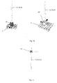
Figure 10 shows a schematic demonstration of possible variants of first-type joints of the invention; -
Figure 11 shows a detail of an alternative connection of the vertical rod with the spherical joint; -
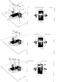
Figure 12 shows a schematic demonstration of motion of a subject with the apparatus of the invention, where the base platform is a motorised mobile platform according to the first embodiment; -
Figure 13 shows a schematic demonstration of motion of a subject with the apparatus of the invention, where the base platform is a motorised platform with a treadmill according to the first embodiment; -
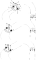
Figure 14 shows a schematic demonstration of motion of a subject with the apparatus of the invention, where the base platform is a motorised mobile platform according to the second embodiment; -
Figure 15 shows a schematic demonstration of motion of a subject with the apparatus of the invention, where the base platform is a motorised platform with a treadmill according to the second embodiment. -
Figure 1 is a schematic demonstration of a lower body part of a standing subject who is supported in the pelvis area by the apparatus of the invention according to the first embodiment; the apparatus allows training of dynamic balance and turning manoeuvres. The apparatus of the invention is represented by a parallel mechanism comprising: abase platform 1, on which first-type joints 2,2' are arranged, said joints being connected with apelvis element 5 by twovertical rods 3,3' via spherical (ball-in-socket)joints 4,4'. Each first-type joint type joint 2 is provided with adrive 6, whereas both degrees of freedom of the first-type joint 2' are provided withdrives - The
drives - The
base platform 1 can be a simple panel, a motorised mobile platform or a motorised platform with a treadmill arranged, wherein the motorised platform can rotate around the vertical axis as will be described hereinbelow. - The apparatus for training dynamic balance and turning manoeuvres during walking according to the first embodiement of the invention has a total of four degrees of freedom with respect to the described components. Three degrees of freedom are motorised (provided with a drive) and one is passive as shown in
Figure 2 to 9 . -
Figure 2 and3 show inclination of the standing subject forward and backwards in a sagittal plane. Inclination forward and backwards can be assisted or guided (in terms of either positional servo guiding or impedance guiding) by themotor drives Figures 4 and5 show inclination of a standing subject to the left and right in a frontal plane. Inclination to the left and right is assisted or guided (in terms of either positional servo guiding or impedance guiding) by thedrive 8. -
Figures 6 and7 show a key degree of freedom of the proposed apparatus of the invention, namely rotation of the pelvis of a standing subject around a vertical axis in the transversal plane in clockwise direction as well as in counterclockwise direction. The described rotation of the standing subject's pelvis can be assisted or guided (in terms of either positional servo guiding or impedance guiding) by adequate operation of thedrives drives -
Figures 8 and9 show a fourth degree of freedom of the proposed apparatus, i. e. passive tilt of the standing subject's pelvis forward and backwards in the sagittal plane. This degree of freedom is controlled by the standing subject. - All
Figures 1 to 9 illustrate the use and functioning of the apparatus of the invention for the purposes of training of dynamic balance and rotation of the body around the vertical axis during standing. - Possible concrete variants of the
universal joint 2,2' which in principle do not change the number of degrees of freedom and the described functionality of the entire apparatus of the invention and do not limit the present invention in any way whatsoever are shown inFigure 10 . Practical implementation of such a joint may be complicated as it requires precise manufacturing and fixation of both axes. - In a first constructional variant each first-
type joint 2,2' can be replaced by avertical spring 20, one end of which is fastened to thebase platform 1 and the other end is fastened to avertical rod - According to a second constructional variant each first-
type joint 2,2' can be replaced by two simplerotational joints 20',20" each having only one axis of rotation, and the first simple joint 20' is fixed to thebase platform 1, whereas the secondsimple joint 20" is fixed to the axis of the first simple joint 20' in a way that the axes of rotation of bothsimple joints 20', 20" are perpendicular, yet do not intersect at the same point. - In the apparatus of the invention and the second embodiment the
vertical rods 3,3' which have a defined, unadjustable length can be replaced by verticallyadjustable rods 30,30' which can contain a translational joint that allows length adjustment of therods 30,30' and each of them can be embodied as a telescopic assembly of two rods and also balanced, for instance with a spring or a similar constructional element that compensates for the weight of thepelvis element 5. A further adjustment option is also possible by a constructional variant where the upper end of therods spherical joints 4,4', which is shown inFigure 11 . - By the replacement of the
vertical rods 3,3' with the vertically adjustabletelescopic rods 30,30' the apparatus of the invention in the second embodiment thus provides for two new degrees of freedom: bias of the pelvis downwards/upwards in the frontal plane and a vertical shift of the pelvis downwards/upwards in all variants shown inFigures 1 to 9 ; a possibility of use of the vertically adjustabletelescopic rods 30,30' is specifically shown inFigures 14 and15 . - In case when the
base platform 1 is a motorised mobile platform, it allows training of dynamic balance and turning manoeuvres during walking on the ground. A sequence of images inFigure 12 first shows walking in one direction, then follows a curve needed for an adequate change of direction during walking, which can be achieved in two ways. In the first way, the walking subject initiates a manoeuvre of turning to a new direction by adequately rotating the pelvis, which is followed by an adequate rotation of the mobile platform and the adequate movement of the apparatus. In the second way, the apparatus initiates rotation of the pelvis, which is followed by an adequate rotation of the mobile platform. In both ways the walking subject has a possibility of training of dynamic balance and turning manoeuvres assisted by motorised degrees of freedom that suit his/her current abilities. - In case when the
base platform 1 is a motorised platform with a treadmill that can rotate around the vertical axis, it allows training of dynamic balance and turning manoeuvres during walking on the treadmill. A sequence of images inFigure 13 shows a turning manoeuvre that is principally identical to the turning manoeuvre shown inFigure 12 , a difference being in that here the mobile platform cannot freely move in a space but is limited to the rotation about the fixed axis of rotation. - In case when the
base platform 1 is a motorised mobile platform according to the second embodiment shown inFigure 14 , it allows in addition to the already disclosed possibilities of manoeuvring with the apparatus of the invention accordng to the first embodiment, as described and shown inFigure 13 , also rotating of the pelvis upwards/downwards in the frontal plane and the vertical shift of the pelvis upwards/downwards. - In case when the
base platform 1 is a motorised platform with a treadmill according to the second embodiment ofFigure 15 that can rotate around the vertical axis, it allows training of dynamic balance and turning manoeuvres during walking on the treadmill. A sequence of images inFigure 15 shows a turning manoeuvre that is principally identical to the turning manoeuvre shown inFigure 14 , a difference being in that the mobile platform in this case is not limited only to rotation around the fixed axis of rotation but the axis of rotation can be anywhere, also for instance in the centre of the conveyor belt. - The inventive aspect of the proposed apparatus for training of dynamic balance and turning manoeuvres during walking of the invention resides especially in a unique kinematic structure that enables the subject to train dynamic balance and rotation around the vertical body axis by a simultaneous motion of the lower body segments in the sagittal and frontal planes while standing, walking on the ground and walking on the treadmill that can rotate around the vertical axis. The motion of the proposed apparatus of the invention is from the biomechanical and physiological aspects in consistence with the motion of a human locomotor apparatus.
Claims (5)
- An apparatus for training dynamic balance and turning manoeuvres during walking, the apparatus comprising: a base platform (1) on which two first-type joints (2, 2') are arranged, each of the two first-type joints (2,2') having a first side connection and a second side connection, and having two degrees of freedom between the first side connection and the second side connection, each of the two first-type joints (2,2') are coupled to the base platform (1) by the first side connection; a pelvis element (5), wherein the pelvis element (5) is connected to two spherical joints (4,4'), the two spherical joints (4,4') each having three degrees of freedom, the two spherical joints (4,4') are respectively connected with two vertical rods 3,3' or vertical telescopic rods (30,30') and wherein the two vertical rods (3,3') or vertical telescopic rods are respectively connected to the second side connection of the two first-type joints (2,2'), wherein the two first-type joints are each spaced apart from the respective two spherical joints (4,4'), wherein the pelvis element (5) is configured to be operably positionable through six degrees of freedom, to, in turn, allow for the following, guiding and supporting of a pelvis of a user positioned therein through six degrees of freedom.
- The apparatus according to claim 1,
characterized in that,
a first of the two first-type joints (2,2') has a first degree of freedom coupled to a first drive (6), and a second of the two first-type joints (2,2') has a first degree of freedom coupled to a second drive (7) and a second degree of freedom coupled to a third drive (8). - The apparatus according to claim 2
characterized in that,
each of the two first-type joints (2,2') comprises one of a vertical spring (20) with a first end defining the first side connection and a second end definig the second side conection, or two simple rotational joints (20',20") coupled to each other, wherein each of the two simple rotational joints (20',20") has single axis of rotation, and wherein a first of the two simple rotational joints (20') is fastened to the base platform (1) and a second of the two simple rotational joints (20") is fastened to the single axis of rotation of the first simple rotational joint (20') so that the single axis of rotation of the first simple rotational joint (20') and the single axis of rotation of the second simple rotational joint (20") are perpendicular and also do not intersect at the same point. - The apparatus according to claim 2
characterized in that,
the first, second and third drives (6,7,8) comprise an active servo drives or passive viscoelastic elements with variable impedance features. - The apparatus according to claim 1,
characterized in that,
the base platform (1) comprises one of: a simple panel; a motorised mobile platform; and a motorised platform with a treadmill arranged wherein the motorized platform with the treadmill can rotate around the vertical axis of the treatmil.
Applications Claiming Priority (3)
| Application Number | Priority Date | Filing Date | Title |
|---|---|---|---|
| SI201200354A SI24224A (en) | 2012-11-21 | 2012-11-21 | Apparatus for measuring the dynamic equilibrium and turning maneuvers during walking |
| SI201300140A SI24383A (en) | 2013-05-30 | 2013-05-30 | Apparatus for training dynamic balance and turning manoeuvres during walking |
| PCT/SI2013/000073 WO2014081400A2 (en) | 2012-11-21 | 2013-11-21 | Apparatus for training dynamic balance and turning manoeuvres during walking |
Publications (2)
| Publication Number | Publication Date |
|---|---|
| EP2922517A2 EP2922517A2 (en) | 2015-09-30 |
| EP2922517B1 true EP2922517B1 (en) | 2018-10-10 |
Family
ID=49958653
Family Applications (1)
| Application Number | Title | Priority Date | Filing Date |
|---|---|---|---|
| EP13821534.8A Not-in-force EP2922517B1 (en) | 2012-11-21 | 2013-11-21 | Apparatus for training dynamic balance and turning manoeuvres during walking |
Country Status (3)
| Country | Link |
|---|---|
| US (1) | US10076461B2 (en) |
| EP (1) | EP2922517B1 (en) |
| WO (1) | WO2014081400A2 (en) |
Families Citing this family (7)
| Publication number | Priority date | Publication date | Assignee | Title |
|---|---|---|---|---|
| KR102335610B1 (en) * | 2014-07-09 | 2021-12-06 | 호코마 아게 | Apparatus for gait training |
| EP3326603B1 (en) | 2016-11-24 | 2020-02-12 | Univerza v Ljubljani Fakulteta za elektrotehniko | Hybrid user-intention-assessment based control system for a smart walking assist system |
| KR101986735B1 (en) * | 2017-09-29 | 2019-06-07 | 전자부품연구원 | Apparatus for simulating snowboard |
| JP7251439B2 (en) | 2019-10-16 | 2023-04-04 | トヨタ自動車株式会社 | Gait training system, device, and method of operation |
| JP7294052B2 (en) | 2019-10-16 | 2023-06-20 | トヨタ自動車株式会社 | Gait training system and method of operation |
| JP7287238B2 (en) | 2019-10-16 | 2023-06-06 | トヨタ自動車株式会社 | Gait training system and method of operation |
| CN111821665B (en) * | 2020-08-10 | 2025-01-07 | 力迈德医疗(广州)有限公司 | Gait balance training equipment |
Citations (2)
| Publication number | Priority date | Publication date | Assignee | Title |
|---|---|---|---|---|
| US1561960A (en) * | 1924-09-08 | 1925-11-17 | Harry A Ungar | Golf positioning apparatus |
| WO2001095980A2 (en) * | 2000-06-14 | 2001-12-20 | Neuroretrain Aps | Balance re-trainer |
Family Cites Families (20)
| Publication number | Priority date | Publication date | Assignee | Title |
|---|---|---|---|---|
| US3463146A (en) * | 1967-01-20 | 1969-08-26 | Arthur Schwartz | Invalid mobility device |
| US3587319A (en) * | 1969-09-30 | 1971-06-28 | William J Andrews | Exercising apparatus |
| USRE28103E (en) * | 1972-10-06 | 1974-08-06 | Izoli izxl | |
| US5174590A (en) * | 1991-07-03 | 1992-12-29 | The United States Of America As Represented By The Administrator Of The National Aeronautics & Space Administration | Compliant walker |
| US5372564A (en) * | 1993-05-05 | 1994-12-13 | Spirito; Pamela J. | Exercise device for exercising the leg abductor, upper arm and postural muscle groups |
| US7125388B1 (en) * | 2002-05-20 | 2006-10-24 | The Regents Of The University Of California | Robotic gait rehabilitation by optimal motion of the hip |
| AU2006236579B2 (en) * | 2005-04-13 | 2011-09-22 | The Regents Of The University Of California | Semi-powered lower extremity exoskeleton |
| US7094187B1 (en) * | 2005-05-06 | 2006-08-22 | Rizzo Peter A | Exercise device |
| US7402127B2 (en) * | 2005-05-06 | 2008-07-22 | Rizzo Peter A | Exercise device |
| JP2007195947A (en) * | 2006-08-24 | 2007-08-09 | Genki Kobo:Kk | Auxiliary equipment for exercise |
| DE602008006080D1 (en) * | 2007-05-28 | 2011-05-19 | Fundacion Fatronik | DEVICE FOR BALANCE AND BODY ORIENTATION SUPPORT |
| CA2724085C (en) * | 2008-05-20 | 2018-10-16 | Berkeley Bionics | Device and method for decreasing energy consumption of a person by use of a lower extremity exoskeleton |
| DE102008029572B4 (en) * | 2008-06-21 | 2011-03-24 | Medica-Medizintechnik Gmbh | Training device for building the muscles of the foot apparatus |
| WO2010011848A1 (en) * | 2008-07-23 | 2010-01-28 | Berkeley Bionics | An exoskeleton and method for controlling a swing leg of the exoskeleton |
| US20100167887A1 (en) * | 2008-12-31 | 2010-07-01 | Michael Berry | Portable exercise, balance and flexibility device and method |
| JP5427231B2 (en) * | 2009-03-05 | 2014-02-26 | マッスル株式会社 | Biped walking movement device |
| US8979720B2 (en) * | 2011-06-06 | 2015-03-17 | Surge Performance Training Llc | Strength and balance exercise apparatus |
| RU2563432C1 (en) * | 2011-08-31 | 2015-09-20 | Медика Медицинтехник Гмбх | Therapeutic simulator for walking |
| US9364735B2 (en) * | 2013-07-12 | 2016-06-14 | Lawrence Beane | Method and apparatus for an exercise support device |
| US9446284B2 (en) * | 2014-03-20 | 2016-09-20 | Kyle Michael Sela | Squat exercising |
-
2013
- 2013-11-21 EP EP13821534.8A patent/EP2922517B1/en not_active Not-in-force
- 2013-11-21 WO PCT/SI2013/000073 patent/WO2014081400A2/en not_active Ceased
-
2015
- 2015-05-21 US US14/718,341 patent/US10076461B2/en not_active Expired - Fee Related
Patent Citations (2)
| Publication number | Priority date | Publication date | Assignee | Title |
|---|---|---|---|---|
| US1561960A (en) * | 1924-09-08 | 1925-11-17 | Harry A Ungar | Golf positioning apparatus |
| WO2001095980A2 (en) * | 2000-06-14 | 2001-12-20 | Neuroretrain Aps | Balance re-trainer |
Also Published As
| Publication number | Publication date |
|---|---|
| EP2922517A2 (en) | 2015-09-30 |
| WO2014081400A3 (en) | 2016-06-09 |
| WO2014081400A2 (en) | 2014-05-30 |
| US20170216126A1 (en) | 2017-08-03 |
| US10076461B2 (en) | 2018-09-18 |
Similar Documents
| Publication | Publication Date | Title |
|---|---|---|
| US10076461B2 (en) | Apparatus for training dynamic balance and turning manoeuvres during walking | |
| US10143606B2 (en) | Sit-to-stand apparatus and method | |
| KR100518154B1 (en) | Apparatus for restoring the balance of the human body | |
| EP2170241B1 (en) | Device for balance and body orientation support | |
| EP2438894B1 (en) | Transfer and mobility device | |
| US9149407B2 (en) | Device for therapeutically treating and/or training the lower extremities of a person | |
| US10786419B2 (en) | Locomotion aid | |
| IL195749A (en) | Apparatus for global corporal mobilization | |
| EP1768636A4 (en) | MARKETING AND BALANCING EXERCISE APPARATUS | |
| KR101433284B1 (en) | Walk Supporting Device for Motion Balancing training Having Motion Adjusting Unit | |
| CN106619014A (en) | Massage armchair for preventing micro-deformation of vertebral column | |
| CN106580630A (en) | Sitting posture spinal column rectification massage chair | |
| JP5626827B2 (en) | Walking training machine | |
| JP2024544656A (en) | Mobility Assistance Devices | |
| KR101433281B1 (en) | Walk Supporting Device For Motion Balancing training | |
| KR20090124768A (en) | Electric Wheelchair for Rehabilitation Exercise of Paraplegic Patients | |
| EP3373878B1 (en) | Robotic mobile and modifiable bed with verticalization | |
| US20250326108A1 (en) | Exoskeleton and method for operating it | |
| CN116920332A (en) | Training device | |
| CN206792635U (en) | A kind of massage armchair of preventing spine Light deformation | |
| US20240350858A1 (en) | Body mobilization apparatus | |
| CN121360021A (en) | Polymorphic rehabilitation helps capable robot | |
| SI24383A (en) | Apparatus for training dynamic balance and turning manoeuvres during walking | |
| SI24224A (en) | Apparatus for measuring the dynamic equilibrium and turning maneuvers during walking | |
| KR20220130134A (en) | Leg Actuator and Gait Rehabilitation Device |
Legal Events
| Date | Code | Title | Description |
|---|---|---|---|
| PUAI | Public reference made under article 153(3) epc to a published international application that has entered the european phase |
Free format text: ORIGINAL CODE: 0009012 |
|
| AK | Designated contracting states |
Kind code of ref document: A2 Designated state(s): AL AT BE BG CH CY CZ DE DK EE ES FI FR GB GR HR HU IE IS IT LI LT LU LV MC MK MT NL NO PL PT RO RS SE SI SK SM TR |
|
| AX | Request for extension of the european patent |
Extension state: BA ME |
|
| DAX | Request for extension of the european patent (deleted) | ||
| R17D | Deferred search report published (corrected) |
Effective date: 20160609 |
|
| 17P | Request for examination filed |
Effective date: 20161209 |
|
| RBV | Designated contracting states (corrected) |
Designated state(s): AL AT BE BG CH CY CZ DE DK EE ES FI FR GB GR HR HU IE IS IT LI LT LU LV MC MK MT NL NO PL PT RO RS SE SI SK SM TR |
|
| 17Q | First examination report despatched |
Effective date: 20171207 |
|
| GRAP | Despatch of communication of intention to grant a patent |
Free format text: ORIGINAL CODE: EPIDOSNIGR1 |
|
| RIC1 | Information provided on ipc code assigned before grant |
Ipc: A63B 26/00 20060101ALI20180704BHEP Ipc: A63B 69/00 20060101ALI20180704BHEP Ipc: A63B 22/00 20060101ALI20180704BHEP Ipc: A63B 22/14 20060101ALI20180704BHEP Ipc: A61H 3/00 20060101AFI20180704BHEP Ipc: A61H 3/04 20060101ALI20180704BHEP Ipc: A63B 22/02 20060101ALI20180704BHEP Ipc: A63B 21/00 20060101ALI20180704BHEP |
|
| INTG | Intention to grant announced |
Effective date: 20180726 |
|
| GRAS | Grant fee paid |
Free format text: ORIGINAL CODE: EPIDOSNIGR3 |
|
| GRAA | (expected) grant |
Free format text: ORIGINAL CODE: 0009210 |
|
| AK | Designated contracting states |
Kind code of ref document: B1 Designated state(s): AL AT BE BG CH CY CZ DE DK EE ES FI FR GB GR HR HU IE IS IT LI LT LU LV MC MK MT NL NO PL PT RO RS SE SI SK SM TR |
|
| REG | Reference to a national code |
Ref country code: GB Ref legal event code: FG4D |
|
| REG | Reference to a national code |
Ref country code: CH Ref legal event code: EP Ref country code: AT Ref legal event code: REF Ref document number: 1050393 Country of ref document: AT Kind code of ref document: T Effective date: 20181015 |
|
| REG | Reference to a national code |
Ref country code: IE Ref legal event code: FG4D |
|
| REG | Reference to a national code |
Ref country code: DE Ref legal event code: R096 Ref document number: 602013044965 Country of ref document: DE |
|
| REG | Reference to a national code |
Ref country code: NL Ref legal event code: MP Effective date: 20181010 |
|
| REG | Reference to a national code |
Ref country code: LT Ref legal event code: MG4D |
|
| REG | Reference to a national code |
Ref country code: AT Ref legal event code: MK05 Ref document number: 1050393 Country of ref document: AT Kind code of ref document: T Effective date: 20181010 |
|
| PG25 | Lapsed in a contracting state [announced via postgrant information from national office to epo] |
Ref country code: NL Free format text: LAPSE BECAUSE OF FAILURE TO SUBMIT A TRANSLATION OF THE DESCRIPTION OR TO PAY THE FEE WITHIN THE PRESCRIBED TIME-LIMIT Effective date: 20181010 |
|
| PG25 | Lapsed in a contracting state [announced via postgrant information from national office to epo] |
Ref country code: NO Free format text: LAPSE BECAUSE OF FAILURE TO SUBMIT A TRANSLATION OF THE DESCRIPTION OR TO PAY THE FEE WITHIN THE PRESCRIBED TIME-LIMIT Effective date: 20190110 Ref country code: LT Free format text: LAPSE BECAUSE OF FAILURE TO SUBMIT A TRANSLATION OF THE DESCRIPTION OR TO PAY THE FEE WITHIN THE PRESCRIBED TIME-LIMIT Effective date: 20181010 Ref country code: FI Free format text: LAPSE BECAUSE OF FAILURE TO SUBMIT A TRANSLATION OF THE DESCRIPTION OR TO PAY THE FEE WITHIN THE PRESCRIBED TIME-LIMIT Effective date: 20181010 Ref country code: IS Free format text: LAPSE BECAUSE OF FAILURE TO SUBMIT A TRANSLATION OF THE DESCRIPTION OR TO PAY THE FEE WITHIN THE PRESCRIBED TIME-LIMIT Effective date: 20190210 Ref country code: AT Free format text: LAPSE BECAUSE OF FAILURE TO SUBMIT A TRANSLATION OF THE DESCRIPTION OR TO PAY THE FEE WITHIN THE PRESCRIBED TIME-LIMIT Effective date: 20181010 Ref country code: ES Free format text: LAPSE BECAUSE OF FAILURE TO SUBMIT A TRANSLATION OF THE DESCRIPTION OR TO PAY THE FEE WITHIN THE PRESCRIBED TIME-LIMIT Effective date: 20181010 Ref country code: LV Free format text: LAPSE BECAUSE OF FAILURE TO SUBMIT A TRANSLATION OF THE DESCRIPTION OR TO PAY THE FEE WITHIN THE PRESCRIBED TIME-LIMIT Effective date: 20181010 Ref country code: BG Free format text: LAPSE BECAUSE OF FAILURE TO SUBMIT A TRANSLATION OF THE DESCRIPTION OR TO PAY THE FEE WITHIN THE PRESCRIBED TIME-LIMIT Effective date: 20190110 Ref country code: HR Free format text: LAPSE BECAUSE OF FAILURE TO SUBMIT A TRANSLATION OF THE DESCRIPTION OR TO PAY THE FEE WITHIN THE PRESCRIBED TIME-LIMIT Effective date: 20181010 Ref country code: PL Free format text: LAPSE BECAUSE OF FAILURE TO SUBMIT A TRANSLATION OF THE DESCRIPTION OR TO PAY THE FEE WITHIN THE PRESCRIBED TIME-LIMIT Effective date: 20181010 |
|
| PG25 | Lapsed in a contracting state [announced via postgrant information from national office to epo] |
Ref country code: AL Free format text: LAPSE BECAUSE OF FAILURE TO SUBMIT A TRANSLATION OF THE DESCRIPTION OR TO PAY THE FEE WITHIN THE PRESCRIBED TIME-LIMIT Effective date: 20181010 Ref country code: SE Free format text: LAPSE BECAUSE OF FAILURE TO SUBMIT A TRANSLATION OF THE DESCRIPTION OR TO PAY THE FEE WITHIN THE PRESCRIBED TIME-LIMIT Effective date: 20181010 Ref country code: PT Free format text: LAPSE BECAUSE OF FAILURE TO SUBMIT A TRANSLATION OF THE DESCRIPTION OR TO PAY THE FEE WITHIN THE PRESCRIBED TIME-LIMIT Effective date: 20190210 Ref country code: RS Free format text: LAPSE BECAUSE OF FAILURE TO SUBMIT A TRANSLATION OF THE DESCRIPTION OR TO PAY THE FEE WITHIN THE PRESCRIBED TIME-LIMIT Effective date: 20181010 Ref country code: GR Free format text: LAPSE BECAUSE OF FAILURE TO SUBMIT A TRANSLATION OF THE DESCRIPTION OR TO PAY THE FEE WITHIN THE PRESCRIBED TIME-LIMIT Effective date: 20190111 |
|
| REG | Reference to a national code |
Ref country code: CH Ref legal event code: PL |
|
| REG | Reference to a national code |
Ref country code: DE Ref legal event code: R097 Ref document number: 602013044965 Country of ref document: DE |
|
| PG25 | Lapsed in a contracting state [announced via postgrant information from national office to epo] |
Ref country code: LU Free format text: LAPSE BECAUSE OF NON-PAYMENT OF DUE FEES Effective date: 20181121 Ref country code: CZ Free format text: LAPSE BECAUSE OF FAILURE TO SUBMIT A TRANSLATION OF THE DESCRIPTION OR TO PAY THE FEE WITHIN THE PRESCRIBED TIME-LIMIT Effective date: 20181010 Ref country code: IT Free format text: LAPSE BECAUSE OF FAILURE TO SUBMIT A TRANSLATION OF THE DESCRIPTION OR TO PAY THE FEE WITHIN THE PRESCRIBED TIME-LIMIT Effective date: 20181010 Ref country code: DK Free format text: LAPSE BECAUSE OF FAILURE TO SUBMIT A TRANSLATION OF THE DESCRIPTION OR TO PAY THE FEE WITHIN THE PRESCRIBED TIME-LIMIT Effective date: 20181010 |
|
| PLBE | No opposition filed within time limit |
Free format text: ORIGINAL CODE: 0009261 |
|
| STAA | Information on the status of an ep patent application or granted ep patent |
Free format text: STATUS: NO OPPOSITION FILED WITHIN TIME LIMIT |
|
| REG | Reference to a national code |
Ref country code: BE Ref legal event code: MM Effective date: 20181130 |
|
| REG | Reference to a national code |
Ref country code: IE Ref legal event code: MM4A |
|
| PG25 | Lapsed in a contracting state [announced via postgrant information from national office to epo] |
Ref country code: MC Free format text: LAPSE BECAUSE OF FAILURE TO SUBMIT A TRANSLATION OF THE DESCRIPTION OR TO PAY THE FEE WITHIN THE PRESCRIBED TIME-LIMIT Effective date: 20181010 Ref country code: RO Free format text: LAPSE BECAUSE OF FAILURE TO SUBMIT A TRANSLATION OF THE DESCRIPTION OR TO PAY THE FEE WITHIN THE PRESCRIBED TIME-LIMIT Effective date: 20181010 Ref country code: CH Free format text: LAPSE BECAUSE OF NON-PAYMENT OF DUE FEES Effective date: 20181130 Ref country code: EE Free format text: LAPSE BECAUSE OF FAILURE TO SUBMIT A TRANSLATION OF THE DESCRIPTION OR TO PAY THE FEE WITHIN THE PRESCRIBED TIME-LIMIT Effective date: 20181010 Ref country code: SM Free format text: LAPSE BECAUSE OF FAILURE TO SUBMIT A TRANSLATION OF THE DESCRIPTION OR TO PAY THE FEE WITHIN THE PRESCRIBED TIME-LIMIT Effective date: 20181010 Ref country code: LI Free format text: LAPSE BECAUSE OF NON-PAYMENT OF DUE FEES Effective date: 20181130 Ref country code: SK Free format text: LAPSE BECAUSE OF FAILURE TO SUBMIT A TRANSLATION OF THE DESCRIPTION OR TO PAY THE FEE WITHIN THE PRESCRIBED TIME-LIMIT Effective date: 20181010 |
|
| 26N | No opposition filed |
Effective date: 20190711 |
|
| PG25 | Lapsed in a contracting state [announced via postgrant information from national office to epo] |
Ref country code: IE Free format text: LAPSE BECAUSE OF NON-PAYMENT OF DUE FEES Effective date: 20181121 Ref country code: SI Free format text: LAPSE BECAUSE OF FAILURE TO SUBMIT A TRANSLATION OF THE DESCRIPTION OR TO PAY THE FEE WITHIN THE PRESCRIBED TIME-LIMIT Effective date: 20181010 |
|
| PG25 | Lapsed in a contracting state [announced via postgrant information from national office to epo] |
Ref country code: BE Free format text: LAPSE BECAUSE OF NON-PAYMENT OF DUE FEES Effective date: 20181130 |
|
| PG25 | Lapsed in a contracting state [announced via postgrant information from national office to epo] |
Ref country code: MT Free format text: LAPSE BECAUSE OF NON-PAYMENT OF DUE FEES Effective date: 20181121 |
|
| PG25 | Lapsed in a contracting state [announced via postgrant information from national office to epo] |
Ref country code: TR Free format text: LAPSE BECAUSE OF FAILURE TO SUBMIT A TRANSLATION OF THE DESCRIPTION OR TO PAY THE FEE WITHIN THE PRESCRIBED TIME-LIMIT Effective date: 20181010 |
|
| PG25 | Lapsed in a contracting state [announced via postgrant information from national office to epo] |
Ref country code: CY Free format text: LAPSE BECAUSE OF FAILURE TO SUBMIT A TRANSLATION OF THE DESCRIPTION OR TO PAY THE FEE WITHIN THE PRESCRIBED TIME-LIMIT Effective date: 20181010 Ref country code: HU Free format text: LAPSE BECAUSE OF FAILURE TO SUBMIT A TRANSLATION OF THE DESCRIPTION OR TO PAY THE FEE WITHIN THE PRESCRIBED TIME-LIMIT; INVALID AB INITIO Effective date: 20131121 Ref country code: MK Free format text: LAPSE BECAUSE OF NON-PAYMENT OF DUE FEES Effective date: 20181010 |
|
| PGFP | Annual fee paid to national office [announced via postgrant information from national office to epo] |
Ref country code: GB Payment date: 20201111 Year of fee payment: 8 Ref country code: FR Payment date: 20201111 Year of fee payment: 8 Ref country code: DE Payment date: 20201111 Year of fee payment: 8 |
|
| REG | Reference to a national code |
Ref country code: DE Ref legal event code: R119 Ref document number: 602013044965 Country of ref document: DE |
|
| GBPC | Gb: european patent ceased through non-payment of renewal fee |
Effective date: 20211121 |
|
| PG25 | Lapsed in a contracting state [announced via postgrant information from national office to epo] |
Ref country code: GB Free format text: LAPSE BECAUSE OF NON-PAYMENT OF DUE FEES Effective date: 20211121 Ref country code: DE Free format text: LAPSE BECAUSE OF NON-PAYMENT OF DUE FEES Effective date: 20220601 |
|
| PG25 | Lapsed in a contracting state [announced via postgrant information from national office to epo] |
Ref country code: FR Free format text: LAPSE BECAUSE OF NON-PAYMENT OF DUE FEES Effective date: 20211130 |