EP2922486B1 - Mechanically heated catheter - Google Patents
Mechanically heated catheter Download PDFInfo
- Publication number
- EP2922486B1 EP2922486B1 EP14712157.8A EP14712157A EP2922486B1 EP 2922486 B1 EP2922486 B1 EP 2922486B1 EP 14712157 A EP14712157 A EP 14712157A EP 2922486 B1 EP2922486 B1 EP 2922486B1
- Authority
- EP
- European Patent Office
- Prior art keywords
- catheter
- friction
- drive wire
- plug
- catheter tip
- Prior art date
- Legal status (The legal status is an assumption and is not a legal conclusion. Google has not performed a legal analysis and makes no representation as to the accuracy of the status listed.)
- Not-in-force
Links
Images




Classifications
-
- A—HUMAN NECESSITIES
- A61—MEDICAL OR VETERINARY SCIENCE; HYGIENE
- A61B—DIAGNOSIS; SURGERY; IDENTIFICATION
- A61B10/00—Instruments for taking body samples for diagnostic purposes; Other methods or instruments for diagnosis, e.g. for vaccination diagnosis, sex determination or ovulation-period determination; Throat striking implements
- A61B10/02—Instruments for taking cell samples or for biopsy
- A61B10/04—Endoscopic instruments, e.g. catheter-type instruments
-
- A—HUMAN NECESSITIES
- A61—MEDICAL OR VETERINARY SCIENCE; HYGIENE
- A61B—DIAGNOSIS; SURGERY; IDENTIFICATION
- A61B1/00—Instruments for performing medical examinations of the interior of cavities or tubes of the body by visual or photographical inspection, e.g. endoscopes; Illuminating arrangements therefor
- A61B1/012—Instruments for performing medical examinations of the interior of cavities or tubes of the body by visual or photographical inspection, e.g. endoscopes; Illuminating arrangements therefor characterised by internal passages or accessories therefor
- A61B1/018—Instruments for performing medical examinations of the interior of cavities or tubes of the body by visual or photographical inspection, e.g. endoscopes; Illuminating arrangements therefor characterised by internal passages or accessories therefor for receiving instruments
-
- A—HUMAN NECESSITIES
- A61—MEDICAL OR VETERINARY SCIENCE; HYGIENE
- A61B—DIAGNOSIS; SURGERY; IDENTIFICATION
- A61B1/00—Instruments for performing medical examinations of the interior of cavities or tubes of the body by visual or photographical inspection, e.g. endoscopes; Illuminating arrangements therefor
- A61B1/267—Instruments for performing medical examinations of the interior of cavities or tubes of the body by visual or photographical inspection, e.g. endoscopes; Illuminating arrangements therefor for the respiratory tract, e.g. laryngoscopes or bronchoscopes
- A61B1/2676—Bronchoscopes
-
- A—HUMAN NECESSITIES
- A61—MEDICAL OR VETERINARY SCIENCE; HYGIENE
- A61B—DIAGNOSIS; SURGERY; IDENTIFICATION
- A61B10/00—Instruments for taking body samples for diagnostic purposes; Other methods or instruments for diagnosis, e.g. for vaccination diagnosis, sex determination or ovulation-period determination; Throat striking implements
- A61B10/02—Instruments for taking cell samples or for biopsy
- A61B10/0233—Pointed or sharp biopsy instruments
-
- A—HUMAN NECESSITIES
- A61—MEDICAL OR VETERINARY SCIENCE; HYGIENE
- A61B—DIAGNOSIS; SURGERY; IDENTIFICATION
- A61B10/00—Instruments for taking body samples for diagnostic purposes; Other methods or instruments for diagnosis, e.g. for vaccination diagnosis, sex determination or ovulation-period determination; Throat striking implements
- A61B10/02—Instruments for taking cell samples or for biopsy
- A61B10/0233—Pointed or sharp biopsy instruments
- A61B10/0266—Pointed or sharp biopsy instruments means for severing sample
-
- A—HUMAN NECESSITIES
- A61—MEDICAL OR VETERINARY SCIENCE; HYGIENE
- A61B—DIAGNOSIS; SURGERY; IDENTIFICATION
- A61B17/00—Surgical instruments, devices or methods
- A61B17/34—Trocars; Puncturing needles
- A61B17/3417—Details of tips or shafts, e.g. grooves, expandable, bendable; Multiple coaxial sliding cannulas, e.g. for dilating
-
- A—HUMAN NECESSITIES
- A61—MEDICAL OR VETERINARY SCIENCE; HYGIENE
- A61B—DIAGNOSIS; SURGERY; IDENTIFICATION
- A61B8/00—Diagnosis using ultrasonic, sonic or infrasonic waves
- A61B8/08—Clinical applications
- A61B8/0833—Clinical applications involving detecting or locating foreign bodies or organic structures
- A61B8/0841—Clinical applications involving detecting or locating foreign bodies or organic structures for locating instruments
-
- A—HUMAN NECESSITIES
- A61—MEDICAL OR VETERINARY SCIENCE; HYGIENE
- A61B—DIAGNOSIS; SURGERY; IDENTIFICATION
- A61B8/00—Diagnosis using ultrasonic, sonic or infrasonic waves
- A61B8/12—Diagnosis using ultrasonic, sonic or infrasonic waves in body cavities or body tracts, e.g. by using catheters
-
- A—HUMAN NECESSITIES
- A61—MEDICAL OR VETERINARY SCIENCE; HYGIENE
- A61B—DIAGNOSIS; SURGERY; IDENTIFICATION
- A61B8/00—Diagnosis using ultrasonic, sonic or infrasonic waves
- A61B8/44—Constructional features of the ultrasonic, sonic or infrasonic diagnostic device
- A61B8/4444—Constructional features of the ultrasonic, sonic or infrasonic diagnostic device related to the probe
- A61B8/445—Details of catheter construction
-
- A—HUMAN NECESSITIES
- A61—MEDICAL OR VETERINARY SCIENCE; HYGIENE
- A61B—DIAGNOSIS; SURGERY; IDENTIFICATION
- A61B10/00—Instruments for taking body samples for diagnostic purposes; Other methods or instruments for diagnosis, e.g. for vaccination diagnosis, sex determination or ovulation-period determination; Throat striking implements
- A61B10/02—Instruments for taking cell samples or for biopsy
- A61B10/04—Endoscopic instruments, e.g. catheter-type instruments
- A61B2010/045—Needles
-
- A—HUMAN NECESSITIES
- A61—MEDICAL OR VETERINARY SCIENCE; HYGIENE
- A61B—DIAGNOSIS; SURGERY; IDENTIFICATION
- A61B18/00—Surgical instruments, devices or methods for transferring non-mechanical forms of energy to or from the body
- A61B2018/00005—Cooling or heating of the probe or tissue immediately surrounding the probe
- A61B2018/00011—Cooling or heating of the probe or tissue immediately surrounding the probe with fluids
- A61B2018/00023—Cooling or heating of the probe or tissue immediately surrounding the probe with fluids closed, i.e. without wound contact by the fluid
-
- A—HUMAN NECESSITIES
- A61—MEDICAL OR VETERINARY SCIENCE; HYGIENE
- A61B—DIAGNOSIS; SURGERY; IDENTIFICATION
- A61B18/00—Surgical instruments, devices or methods for transferring non-mechanical forms of energy to or from the body
- A61B2018/00053—Mechanical features of the instrument of device
- A61B2018/00059—Material properties
- A61B2018/00089—Thermal conductivity
- A61B2018/00095—Thermal conductivity high, i.e. heat conducting
-
- A—HUMAN NECESSITIES
- A61—MEDICAL OR VETERINARY SCIENCE; HYGIENE
- A61B—DIAGNOSIS; SURGERY; IDENTIFICATION
- A61B18/00—Surgical instruments, devices or methods for transferring non-mechanical forms of energy to or from the body
- A61B2018/00053—Mechanical features of the instrument of device
- A61B2018/00184—Moving parts
- A61B2018/00202—Moving parts rotating
- A61B2018/00208—Moving parts rotating actively driven, e.g. by a motor
-
- A—HUMAN NECESSITIES
- A61—MEDICAL OR VETERINARY SCIENCE; HYGIENE
- A61B—DIAGNOSIS; SURGERY; IDENTIFICATION
- A61B18/00—Surgical instruments, devices or methods for transferring non-mechanical forms of energy to or from the body
- A61B2018/00315—Surgical instruments, devices or methods for transferring non-mechanical forms of energy to or from the body for treatment of particular body parts
- A61B2018/00541—Lung or bronchi
-
- A—HUMAN NECESSITIES
- A61—MEDICAL OR VETERINARY SCIENCE; HYGIENE
- A61B—DIAGNOSIS; SURGERY; IDENTIFICATION
- A61B18/00—Surgical instruments, devices or methods for transferring non-mechanical forms of energy to or from the body
- A61B2018/00571—Surgical instruments, devices or methods for transferring non-mechanical forms of energy to or from the body for achieving a particular surgical effect
- A61B2018/00577—Ablation
-
- A—HUMAN NECESSITIES
- A61—MEDICAL OR VETERINARY SCIENCE; HYGIENE
- A61B—DIAGNOSIS; SURGERY; IDENTIFICATION
- A61B18/00—Surgical instruments, devices or methods for transferring non-mechanical forms of energy to or from the body
- A61B2018/00571—Surgical instruments, devices or methods for transferring non-mechanical forms of energy to or from the body for achieving a particular surgical effect
- A61B2018/00595—Cauterization
-
- A—HUMAN NECESSITIES
- A61—MEDICAL OR VETERINARY SCIENCE; HYGIENE
- A61B—DIAGNOSIS; SURGERY; IDENTIFICATION
- A61B18/00—Surgical instruments, devices or methods for transferring non-mechanical forms of energy to or from the body
- A61B2018/00982—Surgical instruments, devices or methods for transferring non-mechanical forms of energy to or from the body combined with or comprising means for visual or photographic inspections inside the body, e.g. endoscopes
-
- A—HUMAN NECESSITIES
- A61—MEDICAL OR VETERINARY SCIENCE; HYGIENE
- A61B—DIAGNOSIS; SURGERY; IDENTIFICATION
- A61B18/00—Surgical instruments, devices or methods for transferring non-mechanical forms of energy to or from the body
- A61B18/04—Surgical instruments, devices or methods for transferring non-mechanical forms of energy to or from the body by heating
- A61B2018/044—Surgical instruments, devices or methods for transferring non-mechanical forms of energy to or from the body by heating the surgical action being effected by a circulating hot fluid
- A61B2018/046—Surgical instruments, devices or methods for transferring non-mechanical forms of energy to or from the body by heating the surgical action being effected by a circulating hot fluid in liquid form
-
- A—HUMAN NECESSITIES
- A61—MEDICAL OR VETERINARY SCIENCE; HYGIENE
- A61B—DIAGNOSIS; SURGERY; IDENTIFICATION
- A61B90/00—Instruments, implements or accessories specially adapted for surgery or diagnosis and not covered by any of the groups A61B1/00 - A61B50/00, e.g. for luxation treatment or for protecting wound edges
- A61B90/36—Image-producing devices or illumination devices not otherwise provided for
- A61B90/37—Surgical systems with images on a monitor during operation
- A61B2090/376—Surgical systems with images on a monitor during operation using X-rays, e.g. fluoroscopy
-
- A—HUMAN NECESSITIES
- A61—MEDICAL OR VETERINARY SCIENCE; HYGIENE
- A61B—DIAGNOSIS; SURGERY; IDENTIFICATION
- A61B90/00—Instruments, implements or accessories specially adapted for surgery or diagnosis and not covered by any of the groups A61B1/00 - A61B50/00, e.g. for luxation treatment or for protecting wound edges
- A61B90/39—Markers, e.g. radio-opaque or breast lesions markers
- A61B2090/3966—Radiopaque markers visible in an X-ray image
-
- A—HUMAN NECESSITIES
- A61—MEDICAL OR VETERINARY SCIENCE; HYGIENE
- A61M—DEVICES FOR INTRODUCING MEDIA INTO, OR ONTO, THE BODY; DEVICES FOR TRANSDUCING BODY MEDIA OR FOR TAKING MEDIA FROM THE BODY; DEVICES FOR PRODUCING OR ENDING SLEEP OR STUPOR
- A61M25/00—Catheters; Hollow probes
- A61M25/0067—Catheters; Hollow probes characterised by the distal end, e.g. tips
- A61M25/0082—Catheter tip comprising a tool
- A61M25/0084—Catheter tip comprising a tool being one or more injection needles
- A61M2025/0087—Multiple injection needles protruding laterally from the distal tip
-
- A—HUMAN NECESSITIES
- A61—MEDICAL OR VETERINARY SCIENCE; HYGIENE
- A61M—DEVICES FOR INTRODUCING MEDIA INTO, OR ONTO, THE BODY; DEVICES FOR TRANSDUCING BODY MEDIA OR FOR TAKING MEDIA FROM THE BODY; DEVICES FOR PRODUCING OR ENDING SLEEP OR STUPOR
- A61M25/00—Catheters; Hollow probes
- A61M25/0067—Catheters; Hollow probes characterised by the distal end, e.g. tips
- A61M25/0082—Catheter tip comprising a tool
- A61M25/0084—Catheter tip comprising a tool being one or more injection needles
- A61M2025/0089—Single injection needle protruding axially, i.e. along the longitudinal axis of the catheter, from the distal tip
Definitions
- the present invention relates to devices for heat production and delivery catheters. More specifically, the present disclosure relates to devices for mechanically-generated heat delivery and delivery catheters.
- heat e.g., localized hyperthermia, thermal ablation, thermal coagulation, or thermal cautery
- Some representative applications of heat include, but are not limited to destruction of cancerous tissues, destruction or mitigation of infection, and modification of aberrant cells (e.g., asthma therapy).
- electrical energy e.g., radiofrequency ablation
- radiative energy e.g., laser ablation
- acoustic energy e.g., high intensity focused ultrasound
- the present invention provides a catheter to deliver heat as defined in claim 1 and comprising a catheter body comprising an axial lumen having a length extending from a proximal end to a distal end; a hollow catheter tip, wherein the hollow catheter tip is operably connected to the distal end of the axial lumen of the catheter body, and wherein at least a portion of the hollow catheter tip is constructed from a material with a coefficient of friction of 0.2 to 0.8; a friction producing plug, wherein the friction producing plug is disposed within configured to fit inside the hollow catheter tip, and wherein at least a portion of the friction producing plug is constructed from a material with a coefficient of friction of 0.2 to 0.8; a drive wire having a proximal end and a distal end and extending through the length of axial lumen of the catheter body and into the hollow catheter, and wherein the distal end of the drive wire is configured to attach to the friction producing plug; the friction plug configured to being moved by the drive wire, wherein the movement of the friction producing plug is one
- the power source is configured to provide rotational movement to the drive wire; the power source is configured to provide axial translational movement to the drive wire; movement of the drive wire is modulated using a power input selected from the group including: electric motors, ultrasonic horns, piezoelectric devices, mechanical air driven devices, harmonic devices, air driven pistons, solenoids, and electromagnet drivers; wherein the drive wire, the catheter body, or both, are constructed out of a low friction material; the drive wire, the catheter body, or both, are coated in a low friction material; a inner cavity of the catheter body is filled with oil; the hollow catheter tip is constructed out of at least one material selected from the group including: stainless steel, titanium, and nitinol; the friction producing plug is constructed out of at least one material selected from the group including: ceramic, copper, steel, minerals, cellulose, aramid, chopped glass, rubber and brass, and polyether ether ketone; the friction producing plug is formed monolithically out of
- the catheter of the present invention can be used in a method, comprising providing heat inside a human patient using a catheter, comprising providing power to a drive wire, the drive wire having a proximal end and a distal end and extending through the length of an axial lumen of a catheter body, and the distal end of the drive wire is configured to attach to a friction producing plug; the power source is connected to a proximal end of the drive wire; rotationally or axially moving the friction producing plug contained within an axial lumen of a catheter tip which is connected to the drive wire; and dissipating heat from the friction produced by the movement of the friction producing plug outward into a human body through thermally conductive material.
- Catheters capable of applying or directing heat in the human body may be used in any of a number of clinical applications as mentioned above.
- the devices, systems, and methods described herein are not intended to limit the scope of this disclosure. Rather, it will be apparent to one of skill in the art that the devices, systems, and methods disclosed herein can be used in many clinical applications, including, but not limited to cancer therapies (e.g., carcinoma ablation, hyperthermia, thermal ablation, etc.), mitigation of infection, and asthma therapies (e.g., modification or destruction of aberrant cells), etc.
- cancer therapies e.g., carcinoma ablation, hyperthermia, thermal ablation, etc.
- asthma therapies e.g., modification or destruction of aberrant cells
- such a mechanically heated catheter can be passed down a bronchoscope to treat a patient (e.g., asthma therapies, or possibly pulmonary tumors) using thermal energy generated by friction.
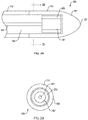
- FIG. 1 illustrates a catheter with a mechanically heated catheter tip 100 (e.g., distal end of the catheter).
- FIG . 1A & 1B illustrate cross sections of the mechanically heated catheter tip 100.
- FIG . 1C illustrates an external view of the mechanically heated catheter tip 100.
- the mechanically heated catheter tip 100 can include a catheter body 110, an axial lumen 121 having a length extending from a proximal end 119 to a distal end 120, a catheter tip distal end 120, a friction producing plug 130, a drive wire 140, a drive wire diameter 150, a catheter high friction material 160, and a thermally conductive catheter tip 170.
- the high friction material may be a material with a coefficient of friction of 0.2 to 0.8, or more preferably a material with a coefficient of friction of 0.4 to 0.7.
- the friction producing plug 130 which can be in substantially uniform contact with the inside of the thermally conductive catheter tip 170 (and therefore the catheter high friction material 160) can be moved by the drive wire 140.
- the movement of the friction producing plug 130 can be either rotational about the axis of the catheter body 110, or it may be axial along the longitudinal axis of the catheter body 110.
- the movement of the friction producing plug 130 across the inner surface of the thermally conductive catheter tip 170, which can be composed of catheter high friction material 160 generates friction. With sufficient power provided by the drive wire 140 and time, the friction produced upon the movement of the friction producing plug 130 generates heat.
- the power of the drive wire 140 can be converted by the interaction of the surface of the friction producing plug 130 and the inner wall of the thermally conductive catheter tip 170 (e.g., the catheter high friction material 160) into thermal energy.
- the thermal energy generated by the drive wire 140 and catheter high friction material 160 can heat the catheter high friction material 160, and consequently the thermally conductive catheter tip 170, which may therefore be used for therapeutic applications of heat.
- the magnitude of thermal energy generated by the catheter with a mechanically heated catheter tip 100 can be modulated by a user by increasing or decreasing the power applied through the drive wire 140 (e.g., a user may decrease the drive wire's 140 rotational speed or may increase the speed at which the drive wire 140 oscillates axially).
- the catheter with a mechanically heated catheter tip 100 can have an external diameter (e.g., the external diameter of the catheter body 110 and thermally conductive catheter tip 170) in the range of about 3-35 French, preferably about 7-31 French, and more preferably about 17-21 French, including about 19 French or any other diameter which will allow the construction and operation of a catheter with a mechanically heated catheter tip 100.
- the anastomosis of the catheter body 110 and the thermally conductive catheter tip 170 is substantially flush, thereby advantageously facilitating passage of the catheter 100 through the target vessel(s).
- the drive wire diameter 150 can be large (e.g., substantially equivalent to the diameter of the friction producing plug 130 (and therefore substantially equivalent to the inner diameter of the thermally conductive catheter tip 170)).
- the drive wire 140 and/or the catheter body 110 can be constructed out of a low friction material to advantageously reduce energy and power loss along the length of the drive wire 140 and allow the maximum delivery of energy to the friction producing plug 130 and the maximum amount of thermal energy generation.
- the exterior surface of the drive wire 140 and/or the interior surface of the catheter body 110 may be coated in a low friction material to advantageously reduce energy and power loss along the length of the drive wire 140 and allow the maximum delivery of energy to the friction producing plug 130 and the maximum amount of heat generation.
- low friction materials which may be used to construct a large diameter drive wire 140 and/or catheter body 111 include: stainless steel, nitinol, titanium, polytetrafluoroethylene, ceramics, FEP, high density polyethylene, and oil impregnated materials.
- low friction materials which may be used to coat a large diameter drive wire 140 and/ internal surface of a catheter body 110 include: polytetrafluoroethylene, expanded polytetrafluoroethylene, ceramic coatings, FEP, high density polyethylene, and oil impregnated metals.
- the inner cavity of the catheter body 110 surrounding the drive wire 140 can be filled with an oil to advantageously decrease friction between the catheter wall and the drive wire 140.
- the drive wire diameter 150 can be small (e.g., substantially smaller than the diameter of the friction producing plug 130).
- the material out of which the drive wire 140 is constructed can be given more latitude than when the drive wire diameter 150 is substantially equivalent to the diameter of the friction producing plug 130. For example, there can be less interaction between the outer surface of the drive wire 140 and the inner surface of the catheter body 110. However, even in these examples, low friction materials may be advantageously used.
- Some representative examples of materials which can be used to construct a small diameter drive wire 140 include: stainless steel, nitinol, and titanium.
- low friction materials which can be used to construct a small diameter drive wire 140, not meant to limit the scope of this disclosure, include: polymeric materials (e.g., high density polyethylene, polytetrafluoroethylene, polyamides (i.e., nylon)), and composite materials.
- polymeric materials e.g., high density polyethylene, polytetrafluoroethylene, polyamides (i.e., nylon)
- composite materials e.g., polymeric materials, e.g., high density polyethylene, polytetrafluoroethylene, polyamides (i.e., nylon)
- composite materials e.g., polyamides (i.e., nylon)
- the exterior surface of the small diameter drive wire 140 and/or the interior surface of the catheter body 110 may be coated in a low friction material to advantageously reduce energy and power loss along the length of the drive wire 140 and allow the maximum delivery of energy to the friction producing plug 130 and the maximum amount of heat generation.
- low friction materials which may be used to coat a small diameter drive wire 140 and/ internal surface of a catheter body 110 include: polytetrafluoroethylene, expanded polytetrafluoroethylene, ceramic coatings, FEP, high density polyethylene, and oil impregnated metals.
- the inner cavity of the catheter body 110 surrounding the small diameter drive wire 140 i.e. hollow catheter tip 185) can be filled with an oil to advantageously decrease friction between the catheter wall and the drive wire 140.
- the friction producing plug 130 has a diameter that is substantially equivalent to the inner diameter of the thermally conductive catheter tip 170.
- the friction producing plug 130 may be translated axially (e.g., along the axis of the catheter with a mechanically heated catheter tip 100) or rotate (e.g., about the axis of the catheter with a mechanically heated catheter tip 100) without being too tight which can cause binding or being too loose which can cause wobbling.
- the friction producing plug 130 can be cylindrical and homogeneous (e.g., formed monolithically out of a single material), as shown in FIG. 1 .
- the monolithic friction producing plug 130 is formed out of a high friction material, including but not limited to: ceramic, copper, steel, minerals, cellulose, aramid, chopped glass, rubber and brass, polyether ether ketone (i.e., PEEK) or any other high friction material.
- a high friction material including but not limited to: ceramic, copper, steel, minerals, cellulose, aramid, chopped glass, rubber and brass, polyether ether ketone (i.e., PEEK) or any other high friction material.
- the drive wire 140 can be attached to the friction producing plug 130 by any of a number of mechanisms, including threads, adhesive, welding, soldering, expansion clips, grommets, rivets, etc.
- the drive wire 140 can be attached to the friction producing plug 130 by any mechanism allowing either axial translation or rotation of the friction producing plug 130 and drive wire 140.
- the connection between the drive wire 140 and friction producing plug 130 can be of sufficient strength to withstand the torque necessary to generate friction between the friction producing plug 130 and catheter high friction material 160.
- the thermally conductive catheter tip 170 which can have an internal lumen to accommodate the friction producing plug 130, is constructed out of a single material, including but not limited to stainless steel, titanium, nitinol, or any other biocompatible thermally conductive material capable of interacting with the surface of the friction producing plug 130 to generate thermal energy.
- the thermally conductive catheter tip 170 is constructed out of two or more layers, including at least an inner friction producing layer, and an outer, biocompatible thermally conductive layer.
- the inner friction producing layer can be constructed out of a material not necessarily biocompatible (e.g., ceramic, copper, steel, minerals, cellulose, aramid, chopped glass, rubber and brass, or any other high friction material) while the outer layer can be constructed out of a material that is both biocompatible and thermally conductive (e.g., stainless steel). Therefore, the friction producing plug 130 can interact with the inner friction producing layer to optimally generate thermal energy which the outer biocompatible thermally conductive layer can conduct the thermal energy to the target site. In this manner, thermal energy can be delivered to a site while advantageously using bio-incompatible materials optimal for generating the desired thermal energy.
- biocompatible e.g., ceramic, copper, steel, minerals, cellulose, aramid, chopped glass, rubber and brass, or any other high friction material
- the outer layer can be constructed out of a material that is both biocompatible and thermally conductive (e.g., stainless steel). Therefore, the friction producing plug 130 can interact with the inner friction producing layer to optimally generate thermal energy which the outer biocompatible thermally
- the thermally conductive catheter tip 170 includes a catheter tip distal end 120 which is substantially bullet-shaped (as illustrated in Fig. 1 ) to advantageously facilitate navigation through corporeal lumens (e.g., blood vessels).
- the thermally conductive catheter tip 170 can taper from a cylinder where the thermally conductive catheter tip 170 meets the catheter body 110 to a rounded tip at the catheter tip distal end 120 (as shown in FIG. 1C ).
- the thermally conductive catheter tip 170 can have any shape desired.
- the thermally conductive catheter tip 170 is removable from the catheter body 110 by the use of a mechanism such as, but not limited to, threads and clips.
- the thermally conductive catheter tip 170 may be constructed so as to be sterilizable and therefore re-usable.
- the thermally conductive catheter tip 170 is permanently fixed to the catheter body 110.
- the catheter with a mechanically heated catheter tip 100 may be constructed so as to be sterilizable and therefore re-usable.
- the catheter with a mechanically heated catheter tip 100 can be constructed so as to be appropriate for only a single use, and therefore be disposable.
- the distal end of the catheter body 110 is anastomosed to the proximal end of the thermally conductive catheter tip 170 as disclosed above.
- the catheter body 110 extends proximally for a distance which can be in the range of about 50-3000 cm, preferably about 200-2250 cm, and more preferably about 500-750 cm, including about 600 cm or any other length needed to reach the target site.
- the drive wire 140 exits the proximal end of the catheter body 110 where the drive wire 140 is coupled to a power source 180 (as shown in FIG. ID).
- the drive wire 140 may have a proximal end (142) and a distal end (141).
- the power source 180 is an oscillator which translates the drive wire 140 back and forth along the axis of the catheter body 110. Translating the drive wire 140 along the axis of the catheter body 110 can translate the friction producing plug 130 along the catheter high friction material 160 of the internal lumen of the thermally conductive catheter tip 170 thereby generating friction-induced thermal energy.
- the power source 180 can be any of the mechanisms including, but not limited to, electric motors, ultrasonic horns, piezoelectric devices, mechanical air driven devices, harmonic devices, air driven pistons, solenoids, or electromagnet drivers, or any other mechanism capable of rapidly oscillating the drive wire 140.
- compressed air can be used to drive a mini turbine which can oscillate the drive wire 140 at high frequencies.
- air flowing over a flexible membrane can create a vibration harmonic which can create a translational (e.g., back and forth motion) on the drive wire 140.
- the power source 180 also referred to as the drive wire power source, is a rotator which rotates the drive wire 140 about the longitudinal axis of the catheter body 110. Rotating the drive wire 140 about the longitudinal axis of the catheter body 110 could therefore rotate the friction producing plug 130 against the catheter high friction material 160 inside the internal lumen of the hollow catheter tip (185) thereby generating friction-induced thermal energy.
- the drive wire power source 180 can be any of the mechanisms including, but not limited to, electric motors, ultrasonic horns, piezoelectric devices, mechanical air driven devices, harmonic devices, air driven pistons, or any other mechanism capable of rapidly rotating the drive wire 140.
- compressed air can be used to drive a mini turbine which can rotate the drive wire 140 at high frequencies.
- the power generated and released at the thermally conductive catheter tip 170 would be in the form of heat and would directly drive the rate of heat transfer through the tissue.
- the power could be the same for a system using mechanical, electrical, radiative, or acoustic energy. However, there can be a difference in how the power is converted to therapeutic heat.
- the power is already in the form of heat, whereas in many other systems, the energy may be required to pass through the resistance of the tissue prior to generate heat (e.g., resistance for electricity, absorption for light, and absorption for sound, etc.).
- FIG. 2 illustrates a second catheter with a mechanically heated catheter tip 200.
- the second catheter tip 200 includes a catheter body 110', a thermally conductive catheter tip 170' constructed out of catheter high friction material 160', a catheter tip distal end 120', a drive wire 140', a friction producing plug 130' and a high friction coating 230.
- the second catheter tip 200 can function in a manner similar to the catheter with a mechanically heated catheter tip 100 of FIG. 1 .
- the friction producing plug 130' of FIG. 2 can be formed out of two or more separate materials.
- the inner core is made out of a first material then coated with a high friction coating 230.
- FIG. 2B shows such a high friction coating 230 coated friction producing plug 130' in cross section view perpendicular to the longitudinal axis of the second catheter tip 200.
- the high friction coating 230 covering the friction producing plug 130' can interact with the catheter high friction material 160' out of which the thermally conductive catheter tip 170' can be constructed.
- the use of a high friction coating 230 can allow the use of less high friction material which can advantageously reduce costs, can allow the use of brittle materials (which may not attach well to the drive wire 140'), or can promote better or firmer connection between the friction producing plug 130' and the drive wire 140'.
- FIG. 3 illustrates a third catheter with a mechanically heated catheter tip 300.
- the third catheter tip 300 can include a catheter body 110', a thermally conductive catheter tip 170' constructed out of catheter high friction material 160', a catheter tip distal end 120', a drive wire 140', a cylindrical, spherical or bullet-shaped friction producing plug (i.e., 310, 320, or 330, respectively), and a plug stop 340.
- the third catheter tip 300 functions in a manner similar to the catheter with a mechanically heated catheter tip 100 of FIG. 1 .
- the friction producing plug may be cylindrical as illustrated by the locked cylindrical friction producing plug 310 of FIG. 3A .
- the friction producing plug may be spherical as illustrated by the locked spherical friction producing plug 320 of FIG. 3B .
- the friction producing plug may be bullet-shaped as illustrated by the locked bullet-shaped friction producing plug 330 of FIG. 3C .
- the plug stop 340 serves to substantially eliminate axial translation of, or "locks", the locked cylindrical friction producing plug 310 of FIG. 3A , the locked spherical friction producing plug 320 of FIG. 3B , and the locked bullet-shaped friction producing plug 330 of FIG. 3C .
- the locking plug stop 340 can be combined with rotation of the drive wire 140' about the catheter's longitudinal axis to advantageously reduce or eliminate substantially all axial translation of the friction producing plug, reduce or eliminate substantially all vibration caused by that axial translation, and/or keep the friction producing plug in the proper friction-producing zone within the thermally conductive catheter tip 170', thereby advantageously simplifying operation.
- the plug stop 340 can combine an allowed fixed distance of axial translation with friction plug oscillation along the catheter's longitudinal axis to advantageously keep the friction producing plug in the proper friction-producing zone within the thermally conductive catheter tip 170' thereby advantageously simplifying operation.
- the plug stop 340 can be any structure capable of restricting axial translation of the friction producing plug, such as the continuous flange-style plug stop 340 illustrated in FIG. 3A, FIG. 3B , and FIG . C.
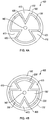
- FIG. 4 illustrates a cross sectional view (perpendicular to the longitudinal axis of the catheter) of a fourth catheter with a mechanically heated catheter tip 400.
- the fourth catheter tip 400 as illustrated in FIG. 4A and 4B can include a friction producing plug 130' a drive wire 140', a thermally conductive catheter tip 170' constructed out of catheter high friction material 160', at least one aligning ridge 410, and/or at least one aligning trench 420.
- the fourth catheter tip 400 can operate in substantially the same manner as the catheter with a mechanically heated catheter tip 100 of FIG. 1 .
- the aligning ridge(s) 410 and the aligning trench(s) 420 of the fourth catheter tip 400 can prevent substantially all rotation about the longitudinal axis of the catheter.
- the fourth catheter tip 400 permits primarily only axial oscillation of the friction producing plug 130'.
- the thermally conductive catheter tip 170' can include one or more aligning ridges 410 and the friction producing plug 130' can include the same number of aligning trenches 420.
- the aligning ridges 410 of the thermally conductive catheter tip 170' fit into the aligning trenches 420 of the friction producing plug 130' allowing the friction producing plug 130' to ride axially along the aligning ridges 410 during oscillation.
- aligning ridge 410 there can be only one aligning ridge 410. In other examples, there can be multiple aligning ridges 410 in the range of about 2-6 ridges, and about 2-4 ridges, including 3 ridges or any other number of ridges which guides the friction producing plug 130' upon axial oscillation.
- the aligning ridges 410 may be constructed out of catheter high friction material 160' as shown in FIG. 4A . In other examples, the aligning ridges 410 may be constructed out of a low friction material as shown in FIG. 4B .
- the entire friction producing plug 130', and therefore the entire surface of the aligning trenches 420 is constructed out of a high friction material (as shown in FIG. 4A ).
- the friction producing plug 130' is constructed out of at least two separate materials (as disclosed in the discussion of FIG. 2 ).
- substantially the entire surface of the aligning trenches 420 can be constructed out of a material distinct from the high friction coating 230' (e.g., a low friction material), as shown in FIG. 4B .
- the fourth catheter tip 400 which includes at least one aligning ridge 410 and at least one aligning trench 420 can include a plug stop 340 as discussed with respect to FIG. 3 .
- FIG. 5 illustrates a fifth catheter with a targeted mechanically heated catheter tip 500.
- the fifth catheter tip 500 includes a catheter body 110', a thermally conductive catheter tip 170' constructed out of both catheter high friction material 160' and catheter thermally insulating material 510, a catheter tip distal end 120', a friction producing plug 130', and a drive wire 140'.
- the fifth catheter tip 500 operates in a manner substantially the same as the catheter with a mechanically heated catheter tip 100 of FIG. 1 .
- the thermally conductive catheter tip 170' of the fifth catheter tip 500 includes a window 550 of catheter high friction material 160'.
- the bulk of the thermally conductive catheter tip 170' (excluding the window 550 of catheter high friction material 160') can be constructed out of catheter thermally insulating material 510.
- the window 550 will produce and conduct heat thereby advantageously permitting enhanced targeting of the thermal energy generated by the friction producing plug 130'.
- the window 550 can be any shape desired and can be located anywhere practicable on the thermally conductive catheter tip 170'.
- the window 550 can be a single concentric band around the entirety of the thermally conductive catheter tip 170' as shown in FIG. 5A .
- the window 550 can be a single circle on only one side of the thermally conductive catheter tip 170' (not shown).
- catheter thermally insulating material 510 appropriate for forming on or with the thermally conductive catheter tip 170', as illustrated in FIG. 5A , include, but are not limited to, polymers (e.g., polytetrafluoroethylene, polyethylene, etc.), rubber, and polycarbonate, or any other biocompatible thermal insulator.
- the thermally conductive catheter tip 170' of the fifth catheter tip 500 is constructed monolithically out of catheter high friction material 160' then selectively coated in catheter thermally insulating material 510 to produce a window 550.
- the coating of catheter thermally insulating material 510 can be an inlay, an onlay, or any other type of coating that allows selective exposure of the catheter high friction material 160'.
- only the window 550 not covered by the catheter thermally insulating material 510 will allow the conductance of heat, thereby advantageously permitting enhanced targeting of the thermal energy generated by the friction producing plug friction producing plug 130'.
- catheter thermally insulating material 510 appropriate for coating the thermally conductive catheter tip 170' as illustrated in FIG. 5B include, but are not limited to, polymers (e.g., polytetrafluoroethylene, polyethylene, etc.), rubber, and polycarbonate, or any other biocompatible thermal insulator.
- FIG. 6A and FIG. 6B illustrate a sixth catheter with a targeted mechanically heated catheter tip 600.
- the sixth catheter tip 600 includes a catheter body 110', a friction producing plug 130', a drive wire 140', a catheter tip distal end 120', a catheter thermally insulating material 510', at least one aligning ridge 410, at least one aligning trench 420, catheter thermally insulating material 510', high friction coating 230, and a high friction window 610.
- the sixth catheter tip operates in a manner substantially the same as the fourth catheter with a mechanically heated catheter tip 400 of FIG. 4 .
- the sixth catheter tip 600 combines the aligning ridges 410 of FIG. 4 and the high friction coating 230 of FIG.
- FIG. 2B and 4B to permanently align the high friction coating 230 on the friction producing plug 130' with the external high friction window 610 (similar to the window 550 of FIG. 5 ).
- the various examples discussed in the previous figures, notably FIG. 2 , FIG. 4 , and FIG. 5 can also be applied to FIG. 6A and FIG. 6B .
- a heat conductive gel may be placed in the treatment region or airway before the probe is placed to administer treatment.
- the heat conductive gel may conduct heat away from the probe into the target tissue more efficiently than air.
- Some examples of heat conductive gel include saline absorbing gel, saline gel, sodium polyacrylate, acrylic acid crosslinked sodium salt, polyacrylic acid crosslinked sodium salt such as Waste Lock brand super absorbent 770 manufactured by M2 Polymer, water based gel lubricant such as Femglide used on catheters and equipment, or the like.
- the systems for mechanically heated catheters disclosed herein can provide for an improved catheter for thermal application because, for example, it provides thermal energy directly without the need for any electricity in the body.
- the mechanically heated catheters may not require the complicated electrical systems that other thermal catheter systems often require to heat tissues as they are purely mechanical-rather, they can create heat directly which can be directly conducted or convected into the target tissue site.
Landscapes
- Health & Medical Sciences (AREA)
- Life Sciences & Earth Sciences (AREA)
- Surgery (AREA)
- Veterinary Medicine (AREA)
- Heart & Thoracic Surgery (AREA)
- Medical Informatics (AREA)
- Molecular Biology (AREA)
- Engineering & Computer Science (AREA)
- Animal Behavior & Ethology (AREA)
- General Health & Medical Sciences (AREA)
- Public Health (AREA)
- Pathology (AREA)
- Biomedical Technology (AREA)
- Nuclear Medicine, Radiotherapy & Molecular Imaging (AREA)
- Radiology & Medical Imaging (AREA)
- Biophysics (AREA)
- Physics & Mathematics (AREA)
- Optics & Photonics (AREA)
- Pulmonology (AREA)
- Otolaryngology (AREA)
- Physiology (AREA)
- Surgical Instruments (AREA)
- Media Introduction/Drainage Providing Device (AREA)
- Endoscopes (AREA)
- Ultra Sonic Daignosis Equipment (AREA)
- Infusion, Injection, And Reservoir Apparatuses (AREA)
Description
- The present invention relates to devices for heat production and delivery catheters. More specifically, the present disclosure relates to devices for mechanically-generated heat delivery and delivery catheters.
- The application of heat (e.g., localized hyperthermia, thermal ablation, thermal coagulation, or thermal cautery) to the human body is a common therapy and has many clinical applications. Some representative applications of heat include, but are not limited to destruction of cancerous tissues, destruction or mitigation of infection, and modification of aberrant cells (e.g., asthma therapy). Currently used methods for the clinical application of heat to tissues entail heat generation by employing electrical energy (e.g., radiofrequency ablation), radiative energy (e.g., laser ablation), and/or acoustic energy (e.g., high intensity focused ultrasound).
- The aforementioned methods have several limitations, including, in some applications, the shared shortcoming of large generator size. Large generators are undesirable because they tend to be cumbersome to transport from bedside to bedside. Furthermore, such generators are frequently expensive, thereby increasing the costs of patient care. For example, electrical energy requires a high frequency generator; radiation energy requires a microwave generator or laser pump; and acoustic energy requires an ultrasonic transducer. Moreover, many currently used methods of heat generation for clinical applications necessitate the use of electricity for proper operation and may suffer from poor control over the thermal temperature rise in the tissue itself. Furthermore, it may be undesirable to pass electric currents through the body.
US6176856B1 describes a catheter for producing heat by friction of a rotating shaft in a distal bearing.US2009143776A1 describes a treatment catheter in which treastment fluid may be heated by a friction device. - Accordingly, there is a need for improved devices, systems and methods for creating mechanically-based heat generation for tissue treatment and clinical applications.
- The present invention provides a catheter to deliver heat as defined in claim 1 and comprising a catheter body comprising an axial lumen having a length extending from a proximal end to a distal end; a hollow catheter tip, wherein the hollow catheter tip is operably connected to the distal end of the axial lumen of the catheter body, and wherein at least a portion of the hollow catheter tip is constructed from a material with a coefficient of friction of 0.2 to 0.8; a friction producing plug, wherein the friction producing plug is disposed within configured to fit inside the hollow catheter tip, and wherein at least a portion of the friction producing plug is constructed from a material with a coefficient of friction of 0.2 to 0.8; a drive wire having a proximal end and a distal end and extending through the length of axial lumen of the catheter body and into the hollow catheter, and wherein the distal end of the drive wire is configured to attach to the friction producing plug; the friction plug configured to being moved by the drive wire, wherein the movement of the friction producing plug is one of a rotational movement about an axis of the catheter body or an axial movement along a longitudinal axis of the catheter body; and a power source, wherein the power source is configured to attach to the proximal end of the drive wire, and wherein the hollow catheter tip contains thermally conductive material.
- Preferred embodiments are defined by the dependent claims which concern the following features: the power source is configured to provide rotational movement to the drive wire; the power source is configured to provide axial translational movement to the drive wire; movement of the drive wire is modulated using a power input selected from the group including: electric motors, ultrasonic horns, piezoelectric devices, mechanical air driven devices, harmonic devices, air driven pistons, solenoids, and electromagnet drivers; wherein the drive wire, the catheter body, or both, are constructed out of a low friction material; the drive wire, the catheter body, or both, are coated in a low friction material; a inner cavity of the catheter body is filled with oil; the hollow catheter tip is constructed out of at least one material selected from the group including: stainless steel, titanium, and nitinol; the friction producing plug is constructed out of at least one material selected from the group including: ceramic, copper, steel, minerals, cellulose, aramid, chopped glass, rubber and brass, and polyether ether ketone; the friction producing plug is formed monolithically out of a single material; the friction producing plug is formed in a shape selected from the group including: spherical, cylindrical, and bullet shaped; the catheter body comprises a plug stop; a shape of the plug stop is selected from a group consisting of continuous flange-style and bullet shaped; the catheter tip is coated in thermally insulating material and a heat conductive gel is placed in a treatment region before a treatment is applied; the catheter is configured to provide heat inside a human patient.
- The catheter of the present invention can be used in a method, comprising providing heat inside a human patient using a catheter, comprising providing power to a drive wire, the drive wire having a proximal end and a distal end and extending through the length of an axial lumen of a catheter body, and the distal end of the drive wire is configured to attach to a friction producing plug; the power source is connected to a proximal end of the drive wire; rotationally or axially moving the friction producing plug contained within an axial lumen of a catheter tip which is connected to the drive wire; and dissipating heat from the friction produced by the movement of the friction producing plug outward into a human body through thermally conductive material.
- The foregoing and other features, aspects and advantages of the present disclosure are described in detail below with reference to the drawings of various examples, which are intended to illustrate and not to limit the disclosure. The drawings comprise the following figures in which:
-
Figure 1A illustrates a longitudinal section view of a catheter with a mechanically heated catheter tip. -
Figure 1B illustrates a longitudinal section view of a second catheter with a mechanically heated catheter tip. -
Figure 1C illustrates an external view of a catheter with a mechanically heated catheter tip. -
Figure 1D illustrates a schematic view of a system for heat generation using a catheter with a mechanically heated catheter tip. -
Figure 2A illustrates a longitudinal section view of another catheter with a mechanically heated catheter tip. -
Figure 2B illustrates a section view perpendicular to the longitudinal axis of the catheter with a mechanically heated catheter tip shown inFigure 2A . -
Figure 3A illustrates a longitudinal section view of a catheter with a mechanically heated catheter tip having a plug stop. -
Figure 3B illustrates a longitudinal section view of another catheter with a mechanically heated catheter tip having a plug stop. -
Figure 3C illustrates a longitudinal section view of another catheter with a mechanically heated catheter tip having a plug stop. -
Figure 4A illustrates a section view perpendicular to the longitudinal axis of a catheter with a mechanically heated catheter tip having a grooved friction producing plug. -
Figure 4B illustrates a section view perpendicular to the longitudinal axis of another catheter with a mechanically heated catheter tip having a grooved friction producing plug. -
Figure 5A illustrates a longitudinal section view of a catheter with a mechanically heated catheter tip having a windowed tip. -
Figure 5B illustrates a longitudinal section view of another catheter with a mechanically heated catheter tip having a windowed tip. -
Figure 6A illustrates a longitudinal section view of another catheter with a mechanically heated catheter tip having a windowed tip. -
Figure 6B illustrates a section view perpendicular to the longitudinal axis of the catheter with a mechanically heated catheter tip having a windowed tip shown inFigure 6A . - Catheters capable of applying or directing heat in the human body may be used in any of a number of clinical applications as mentioned above. The devices, systems, and methods described herein are not intended to limit the scope of this disclosure. Rather, it will be apparent to one of skill in the art that the devices, systems, and methods disclosed herein can be used in many clinical applications, including, but not limited to cancer therapies (e.g., carcinoma ablation, hyperthermia, thermal ablation, etc.), mitigation of infection, and asthma therapies (e.g., modification or destruction of aberrant cells), etc. For example, such a mechanically heated catheter can be passed down a bronchoscope to treat a patient (e.g., asthma therapies, or possibly pulmonary tumors) using thermal energy generated by friction.
-
FIG. 1 illustrates a catheter with a mechanically heated catheter tip 100 (e.g., distal end of the catheter).FIG. 1A & 1B illustrate cross sections of the mechanically heatedcatheter tip 100.FIG. 1C illustrates an external view of the mechanically heatedcatheter tip 100. The mechanically heatedcatheter tip 100 can include acatheter body 110, anaxial lumen 121 having a length extending from aproximal end 119 to adistal end 120, a catheter tipdistal end 120, afriction producing plug 130, adrive wire 140, adrive wire diameter 150, a catheterhigh friction material 160, and a thermallyconductive catheter tip 170. It is contemplated that the high friction material may be a material with a coefficient of friction of 0.2 to 0.8, or more preferably a material with a coefficient of friction of 0.4 to 0.7. - In operation, the
friction producing plug 130, which can be in substantially uniform contact with the inside of the thermally conductive catheter tip 170 (and therefore the catheter high friction material 160) can be moved by thedrive wire 140. The movement of thefriction producing plug 130 can be either rotational about the axis of thecatheter body 110, or it may be axial along the longitudinal axis of thecatheter body 110. In further operation, the movement of thefriction producing plug 130 across the inner surface of the thermallyconductive catheter tip 170, which can be composed of catheterhigh friction material 160, generates friction. With sufficient power provided by thedrive wire 140 and time, the friction produced upon the movement of thefriction producing plug 130 generates heat. The power of thedrive wire 140 can be converted by the interaction of the surface of thefriction producing plug 130 and the inner wall of the thermally conductive catheter tip 170 (e.g., the catheter high friction material 160) into thermal energy. The thermal energy generated by thedrive wire 140 and catheterhigh friction material 160 can heat the catheterhigh friction material 160, and consequently the thermallyconductive catheter tip 170, which may therefore be used for therapeutic applications of heat. In yet further operation, the magnitude of thermal energy generated by the catheter with a mechanically heatedcatheter tip 100 can be modulated by a user by increasing or decreasing the power applied through the drive wire 140 (e.g., a user may decrease the drive wire's 140 rotational speed or may increase the speed at which thedrive wire 140 oscillates axially). - In some examples, the catheter with a mechanically heated
catheter tip 100 can have an external diameter (e.g., the external diameter of thecatheter body 110 and thermally conductive catheter tip 170) in the range of about 3-35 French, preferably about 7-31 French, and more preferably about 17-21 French, including about 19 French or any other diameter which will allow the construction and operation of a catheter with a mechanically heatedcatheter tip 100. In some examples, the anastomosis of thecatheter body 110 and the thermallyconductive catheter tip 170 is substantially flush, thereby advantageously facilitating passage of thecatheter 100 through the target vessel(s). - In some examples, the
drive wire diameter 150 can be large (e.g., substantially equivalent to the diameter of the friction producing plug 130 (and therefore substantially equivalent to the inner diameter of the thermally conductive catheter tip 170)). In these examples, thedrive wire 140 and/or thecatheter body 110 can be constructed out of a low friction material to advantageously reduce energy and power loss along the length of thedrive wire 140 and allow the maximum delivery of energy to thefriction producing plug 130 and the maximum amount of thermal energy generation. In other embodiments, rather than being constructed of one homogeneous material, the exterior surface of thedrive wire 140 and/or the interior surface of thecatheter body 110 may be coated in a low friction material to advantageously reduce energy and power loss along the length of thedrive wire 140 and allow the maximum delivery of energy to thefriction producing plug 130 and the maximum amount of heat generation. Representative examples, not meant to limit the scope of this disclosure, of low friction materials which may be used to construct a largediameter drive wire 140 and/or catheter body 111 include: stainless steel, nitinol, titanium, polytetrafluoroethylene, ceramics, FEP, high density polyethylene, and oil impregnated materials. Representative examples, not meant to limit the scope of this disclosure, of low friction materials which may be used to coat a largediameter drive wire 140 and/ internal surface of acatheter body 110 include: polytetrafluoroethylene, expanded polytetrafluoroethylene, ceramic coatings, FEP, high density polyethylene, and oil impregnated metals. In some embodiments, the inner cavity of thecatheter body 110 surrounding thedrive wire 140 can be filled with an oil to advantageously decrease friction between the catheter wall and thedrive wire 140. In some embodiments, thedrive wire diameter 150 can be small (e.g., substantially smaller than the diameter of the friction producing plug 130). In some examples, the material out of which thedrive wire 140 is constructed can be given more latitude than when thedrive wire diameter 150 is substantially equivalent to the diameter of thefriction producing plug 130. For example, there can be less interaction between the outer surface of thedrive wire 140 and the inner surface of thecatheter body 110. However, even in these examples, low friction materials may be advantageously used. Some representative examples of materials which can be used to construct a smalldiameter drive wire 140, not meant to limit the scope of this disclosure, include: stainless steel, nitinol, and titanium. Some representative examples of low friction materials which can be used to construct a smalldiameter drive wire 140, not meant to limit the scope of this disclosure, include: polymeric materials (e.g., high density polyethylene, polytetrafluoroethylene, polyamides (i.e., nylon)), and composite materials. As disclosed with respect to a largediameter catheter body 110, the exterior surface of the smalldiameter drive wire 140 and/or the interior surface of thecatheter body 110 may be coated in a low friction material to advantageously reduce energy and power loss along the length of thedrive wire 140 and allow the maximum delivery of energy to thefriction producing plug 130 and the maximum amount of heat generation. Representative examples, not meant to limit the scope of this disclosure, of low friction materials which may be used to coat a smalldiameter drive wire 140 and/ internal surface of acatheter body 110 include: polytetrafluoroethylene, expanded polytetrafluoroethylene, ceramic coatings, FEP, high density polyethylene, and oil impregnated metals. In some embodiments, the inner cavity of thecatheter body 110 surrounding the small diameter drive wire 140 (i.e. hollow catheter tip 185) can be filled with an oil to advantageously decrease friction between the catheter wall and thedrive wire 140. - In some examples, the
friction producing plug 130 has a diameter that is substantially equivalent to the inner diameter of the thermallyconductive catheter tip 170. In some examples, thefriction producing plug 130 may be translated axially (e.g., along the axis of the catheter with a mechanically heated catheter tip 100) or rotate (e.g., about the axis of the catheter with a mechanically heated catheter tip 100) without being too tight which can cause binding or being too loose which can cause wobbling. In some embodiments, thefriction producing plug 130 can be cylindrical and homogeneous (e.g., formed monolithically out of a single material), as shown inFIG. 1 . In some examples, the monolithicfriction producing plug 130 is formed out of a high friction material, including but not limited to: ceramic, copper, steel, minerals, cellulose, aramid, chopped glass, rubber and brass, polyether ether ketone (i.e., PEEK) or any other high friction material. - In some examples, the
drive wire 140 can be attached to thefriction producing plug 130 by any of a number of mechanisms, including threads, adhesive, welding, soldering, expansion clips, grommets, rivets, etc. In other examples, thedrive wire 140 can be attached to thefriction producing plug 130 by any mechanism allowing either axial translation or rotation of thefriction producing plug 130 and drivewire 140. In examples in which rotation of thefriction producing plug 130 is used, the connection between thedrive wire 140 andfriction producing plug 130 can be of sufficient strength to withstand the torque necessary to generate friction between thefriction producing plug 130 and catheterhigh friction material 160. - In some examples, the thermally
conductive catheter tip 170, which can have an internal lumen to accommodate thefriction producing plug 130, is constructed out of a single material, including but not limited to stainless steel, titanium, nitinol, or any other biocompatible thermally conductive material capable of interacting with the surface of thefriction producing plug 130 to generate thermal energy. In some examples, the thermallyconductive catheter tip 170 is constructed out of two or more layers, including at least an inner friction producing layer, and an outer, biocompatible thermally conductive layer. For example, the inner friction producing layer can be constructed out of a material not necessarily biocompatible (e.g., ceramic, copper, steel, minerals, cellulose, aramid, chopped glass, rubber and brass, or any other high friction material) while the outer layer can be constructed out of a material that is both biocompatible and thermally conductive (e.g., stainless steel). Therefore, thefriction producing plug 130 can interact with the inner friction producing layer to optimally generate thermal energy which the outer biocompatible thermally conductive layer can conduct the thermal energy to the target site. In this manner, thermal energy can be delivered to a site while advantageously using bio-incompatible materials optimal for generating the desired thermal energy. - In some examples, the thermally
conductive catheter tip 170 includes a catheter tipdistal end 120 which is substantially bullet-shaped (as illustrated inFig. 1 ) to advantageously facilitate navigation through corporeal lumens (e.g., blood vessels). In some examples, the thermallyconductive catheter tip 170 can taper from a cylinder where the thermallyconductive catheter tip 170 meets thecatheter body 110 to a rounded tip at the catheter tip distal end 120 (as shown inFIG. 1C ). In some examples, the thermallyconductive catheter tip 170 can have any shape desired. - In some examples, the thermally
conductive catheter tip 170 is removable from thecatheter body 110 by the use of a mechanism such as, but not limited to, threads and clips. In some examples, the thermallyconductive catheter tip 170 may be constructed so as to be sterilizable and therefore re-usable. In some examples, the thermallyconductive catheter tip 170 is permanently fixed to thecatheter body 110. In such examples, the catheter with a mechanicallyheated catheter tip 100 may be constructed so as to be sterilizable and therefore re-usable. In some examples, the catheter with a mechanicallyheated catheter tip 100 can be constructed so as to be appropriate for only a single use, and therefore be disposable. - The distal end of the
catheter body 110 is anastomosed to the proximal end of the thermallyconductive catheter tip 170 as disclosed above. Thecatheter body 110 extends proximally for a distance which can be in the range of about 50-3000 cm, preferably about 200-2250 cm, and more preferably about 500-750 cm, including about 600 cm or any other length needed to reach the target site. Thedrive wire 140 exits the proximal end of thecatheter body 110 where thedrive wire 140 is coupled to a power source 180 (as shown in FIG. ID). Thedrive wire 140 may have a proximal end (142) and a distal end (141). - In some examples, the
power source 180 is an oscillator which translates thedrive wire 140 back and forth along the axis of thecatheter body 110. Translating thedrive wire 140 along the axis of thecatheter body 110 can translate thefriction producing plug 130 along the catheterhigh friction material 160 of the internal lumen of the thermallyconductive catheter tip 170 thereby generating friction-induced thermal energy. In examples in which thepower source 180 is an oscillator, thepower source 180 can be any of the mechanisms including, but not limited to, electric motors, ultrasonic horns, piezoelectric devices, mechanical air driven devices, harmonic devices, air driven pistons, solenoids, or electromagnet drivers, or any other mechanism capable of rapidly oscillating thedrive wire 140. As an illustrative examples, compressed air can be used to drive a mini turbine which can oscillate thedrive wire 140 at high frequencies. In some examples, air flowing over a flexible membrane can create a vibration harmonic which can create a translational (e.g., back and forth motion) on thedrive wire 140. The amount of heat generated in an embodiment using anoscillating power source 180 can be governed by the following equation:
- P = the power generated (dissipated)
- F = the axial force
- d = the distance traveled
- t = time
- This equation shows that a high velocity (d/t), set by a high frequency (e.g., in the ultrasonic range) could require very little displacement to generate a large amount of power.
- In some examples, the
power source 180, also referred to as the drive wire power source, is a rotator which rotates thedrive wire 140 about the longitudinal axis of thecatheter body 110. Rotating thedrive wire 140 about the longitudinal axis of thecatheter body 110 could therefore rotate thefriction producing plug 130 against the catheterhigh friction material 160 inside the internal lumen of the hollow catheter tip (185) thereby generating friction-induced thermal energy. In some examples (e.g., where the drivewire power source 180 is a rotator) the drivewire power source 180 can be any of the mechanisms including, but not limited to, electric motors, ultrasonic horns, piezoelectric devices, mechanical air driven devices, harmonic devices, air driven pistons, or any other mechanism capable of rapidly rotating thedrive wire 140. For example, compressed air can be used to drive a mini turbine which can rotate thedrive wire 140 at high frequencies. The amount of heat generated (and dissipated to tissue) can follow the following form of the energy and power equation (the energy element of this equation applies to the translation system discussed above):
- P = the mechanical power transferred to the tissue In a rotational system, P = τ (rotational velocity))
- Q = the heat flux away from the tissue, driven by the thermal conductivity and convection of the tissue surrounding the tissue being heated.
- M · a = the mass flow rate of the air in the tissue being heated
- M · b = the mass flow rate of the blood in the tissue being heated
- Ca = the heat capacitance of the air
- C b = the heat capacitance of the blood
- ΔTa = the change in temperature of the air in the tissue being heated
- ΔT b = the change in temperature of the blood in the tissue being heated
- M = the mass of the tissue being heated
- C = the heat capacity of the tissue being heated
-

- In the aforementioned equation and physical situation, the power generated and released at the thermally
conductive catheter tip 170 would be in the form of heat and would directly drive the rate of heat transfer through the tissue. The power could be the same for a system using mechanical, electrical, radiative, or acoustic energy. However, there can be a difference in how the power is converted to therapeutic heat. In the system disclosed herein, the power is already in the form of heat, whereas in many other systems, the energy may be required to pass through the resistance of the tissue prior to generate heat (e.g., resistance for electricity, absorption for light, and absorption for sound, etc.). -
FIG. 2 illustrates a second catheter with a mechanicallyheated catheter tip 200. Thesecond catheter tip 200 includes a catheter body 110', a thermally conductive catheter tip 170' constructed out of catheter high friction material 160', a catheter tip distal end 120', a drive wire 140', a friction producing plug 130' and ahigh friction coating 230. In operation, thesecond catheter tip 200 can function in a manner similar to the catheter with a mechanicallyheated catheter tip 100 ofFIG. 1 . - The friction producing plug 130' of
FIG. 2 can be formed out of two or more separate materials. In some examples, the inner core is made out of a first material then coated with ahigh friction coating 230.FIG. 2B shows such ahigh friction coating 230 coated friction producing plug 130' in cross section view perpendicular to the longitudinal axis of thesecond catheter tip 200. Thehigh friction coating 230 covering the friction producing plug 130' can interact with the catheter high friction material 160' out of which the thermally conductive catheter tip 170' can be constructed. The use of ahigh friction coating 230 can allow the use of less high friction material which can advantageously reduce costs, can allow the use of brittle materials (which may not attach well to the drive wire 140'), or can promote better or firmer connection between the friction producing plug 130' and the drive wire 140'. -
FIG. 3 illustrates a third catheter with a mechanicallyheated catheter tip 300. Thethird catheter tip 300 can include a catheter body 110', a thermally conductive catheter tip 170' constructed out of catheter high friction material 160', a catheter tip distal end 120', a drive wire 140', a cylindrical, spherical or bullet-shaped friction producing plug (i.e., 310, 320, or 330, respectively), and aplug stop 340. In operation, thethird catheter tip 300 functions in a manner similar to the catheter with a mechanicallyheated catheter tip 100 ofFIG. 1 . - In some examples, the friction producing plug may be cylindrical as illustrated by the locked cylindrical
friction producing plug 310 ofFIG. 3A . In other examples, the friction producing plug may be spherical as illustrated by the locked sphericalfriction producing plug 320 ofFIG. 3B . In yet other examples the friction producing plug may be bullet-shaped as illustrated by the locked bullet-shaped friction producing plug 330 ofFIG. 3C . - In some examples, the
plug stop 340 serves to substantially eliminate axial translation of, or "locks", the locked cylindricalfriction producing plug 310 ofFIG. 3A , the locked sphericalfriction producing plug 320 ofFIG. 3B , and the locked bullet-shaped friction producing plug 330 ofFIG. 3C . In some examples, the locking plug stop 340 can be combined with rotation of the drive wire 140' about the catheter's longitudinal axis to advantageously reduce or eliminate substantially all axial translation of the friction producing plug, reduce or eliminate substantially all vibration caused by that axial translation, and/or keep the friction producing plug in the proper friction-producing zone within the thermally conductive catheter tip 170', thereby advantageously simplifying operation. In other examples, rather than substantially reducing or eliminating axial translation, the plug stop 340 can combine an allowed fixed distance of axial translation with friction plug oscillation along the catheter's longitudinal axis to advantageously keep the friction producing plug in the proper friction-producing zone within the thermally conductive catheter tip 170' thereby advantageously simplifying operation. Theplug stop 340 can be any structure capable of restricting axial translation of the friction producing plug, such as the continuous flange-style plug stop 340 illustrated inFIG. 3A, FIG. 3B , and FIG. C. -
FIG. 4 illustrates a cross sectional view (perpendicular to the longitudinal axis of the catheter) of a fourth catheter with a mechanicallyheated catheter tip 400. Thefourth catheter tip 400, as illustrated inFIG. 4A and 4B can include a friction producing plug 130' a drive wire 140', a thermally conductive catheter tip 170' constructed out of catheter high friction material 160', at least one aligningridge 410, and/or at least one aligningtrench 420. In operation, thefourth catheter tip 400 can operate in substantially the same manner as the catheter with a mechanicallyheated catheter tip 100 ofFIG. 1 . In some examples, the aligning ridge(s) 410 and the aligning trench(s) 420 of thefourth catheter tip 400 can prevent substantially all rotation about the longitudinal axis of the catheter. In some examples, thefourth catheter tip 400 permits primarily only axial oscillation of the friction producing plug 130'. - In some examples, the thermally conductive catheter tip 170' can include one or more aligning
ridges 410 and the friction producing plug 130' can include the same number of aligningtrenches 420. In these examples, the aligningridges 410 of the thermally conductive catheter tip 170' fit into the aligningtrenches 420 of the friction producing plug 130' allowing the friction producing plug 130' to ride axially along the aligningridges 410 during oscillation. - In some examples, there can be only one aligning
ridge 410. In other examples, there can be multiple aligningridges 410 in the range of about 2-6 ridges, and about 2-4 ridges, including 3 ridges or any other number of ridges which guides the friction producing plug 130' upon axial oscillation. In some examples, the aligningridges 410 may be constructed out of catheter high friction material 160' as shown inFIG. 4A . In other examples, the aligningridges 410 may be constructed out of a low friction material as shown inFIG. 4B . - In some examples, there can be only one aligning
trench 420. In other examples, there can be multiple aligningtrenches 420 in the range of about 2-6 trenches, and about 2-4 trenches, including 3 trenches or any other number of trenches which guides the friction producing plug 130' upon axial oscillation. In some examples, the entire friction producing plug 130', and therefore the entire surface of the aligningtrenches 420, is constructed out of a high friction material (as shown inFIG. 4A ). In other examples, the friction producing plug 130' is constructed out of at least two separate materials (as disclosed in the discussion ofFIG. 2 ). In such examples, substantially the entire surface of the aligningtrenches 420 can be constructed out of a material distinct from the high friction coating 230' (e.g., a low friction material), as shown inFIG. 4B . - In some examples, the
fourth catheter tip 400 which includes at least one aligningridge 410 and at least one aligningtrench 420 can include aplug stop 340 as discussed with respect toFIG. 3 . -
FIG. 5 illustrates a fifth catheter with a targeted mechanicallyheated catheter tip 500. Thefifth catheter tip 500 includes a catheter body 110', a thermally conductive catheter tip 170' constructed out of both catheter high friction material 160' and catheter thermally insulatingmaterial 510, a catheter tip distal end 120', a friction producing plug 130', and a drive wire 140'. In operation, thefifth catheter tip 500 operates in a manner substantially the same as the catheter with a mechanicallyheated catheter tip 100 ofFIG. 1 . - In some examples, as illustrated in
FIG. 5A , the thermally conductive catheter tip 170' of thefifth catheter tip 500 includes awindow 550 of catheter high friction material 160'. In these examples, the bulk of the thermally conductive catheter tip 170' (excluding thewindow 550 of catheter high friction material 160') can be constructed out of catheter thermally insulatingmaterial 510. In some embodiments, thewindow 550 will produce and conduct heat thereby advantageously permitting enhanced targeting of the thermal energy generated by the friction producing plug 130'. Thewindow 550 can be any shape desired and can be located anywhere practicable on the thermally conductive catheter tip 170'. For example, thewindow 550 can be a single concentric band around the entirety of the thermally conductive catheter tip 170' as shown inFIG. 5A . Alternatively, thewindow 550 can be a single circle on only one side of the thermally conductive catheter tip 170' (not shown). Representative examples of catheter thermally insulatingmaterial 510 appropriate for forming on or with the thermally conductive catheter tip 170', as illustrated inFIG. 5A , include, but are not limited to, polymers (e.g., polytetrafluoroethylene, polyethylene, etc.), rubber, and polycarbonate, or any other biocompatible thermal insulator. - In some examples, as illustrated in
FIG. 5B , the thermally conductive catheter tip 170' of thefifth catheter tip 500 is constructed monolithically out of catheter high friction material 160' then selectively coated in catheter thermally insulatingmaterial 510 to produce awindow 550. The coating of catheter thermally insulatingmaterial 510 can be an inlay, an onlay, or any other type of coating that allows selective exposure of the catheter high friction material 160'. In some examples, only thewindow 550 not covered by the catheter thermally insulatingmaterial 510 will allow the conductance of heat, thereby advantageously permitting enhanced targeting of the thermal energy generated by the friction producing plug friction producing plug 130'. The use of a coating of catheter thermally insulatingmaterial 510 as illustrated inFIG. 5B can permit more detailed patterns ofwindows 550 than the constructed inFIG. 5A thereby advantageously allowing a heightened degree of targeting of the heat produced by thefifth catheter tip 500. Representative examples of catheter thermally insulatingmaterial 510 appropriate for coating the thermally conductive catheter tip 170' as illustrated inFIG. 5B include, but are not limited to, polymers (e.g., polytetrafluoroethylene, polyethylene, etc.), rubber, and polycarbonate, or any other biocompatible thermal insulator. -
FIG. 6A and FIG. 6B illustrate a sixth catheter with a targeted mechanicallyheated catheter tip 600. Thesixth catheter tip 600 includes a catheter body 110', a friction producing plug 130', a drive wire 140', a catheter tip distal end 120', a catheter thermally insulating material 510', at least one aligningridge 410, at least one aligningtrench 420, catheter thermally insulating material 510',high friction coating 230, and ahigh friction window 610. In operation, the sixth catheter tip operates in a manner substantially the same as the fourth catheter with a mechanicallyheated catheter tip 400 ofFIG. 4 . Thesixth catheter tip 600 combines the aligningridges 410 ofFIG. 4 and the high friction coating 230 ofFIG. 2B and4B to permanently align the high friction coating 230 on the friction producing plug 130' with the external high friction window 610 (similar to thewindow 550 ofFIG. 5 ). The various examples discussed in the previous figures, notablyFIG. 2 ,FIG. 4 , andFIG. 5 can also be applied toFIG. 6A and FIG. 6B . - In some examples, it is contemplated that a heat conductive gel may be placed in the treatment region or airway before the probe is placed to administer treatment. The heat conductive gel may conduct heat away from the probe into the target tissue more efficiently than air. Some examples of heat conductive gel include saline absorbing gel, saline gel, sodium polyacrylate, acrylic acid crosslinked sodium salt, polyacrylic acid crosslinked sodium salt such as Waste Lock brand super absorbent 770 manufactured by M2 Polymer, water based gel lubricant such as Femglide used on catheters and equipment, or the like.
- The systems for mechanically heated catheters disclosed herein can provide for an improved catheter for thermal application because, for example, it provides thermal energy directly without the need for any electricity in the body. The mechanically heated catheters may not require the complicated electrical systems that other thermal catheter systems often require to heat tissues as they are purely mechanical-rather, they can create heat directly which can be directly conducted or convected into the target tissue site.
- Of course, the foregoing description is not limited to the described features, aspects and advantages the present disclosure. Accordingly, the scope of the invention is defined by the appended claims.
Claims (14)
- A catheter to deliver heat, comprising:a catheter body (110) comprising an axial lumen (121) having a length extending from a proximal end (119) to a distal end (120);a hollow catheter tip (185), wherein the hollow catheter tip is operably connected to the distal end of the axial lumen of the catheter body, and wherein at least a portion of the hollow catheter tip is constructed from a material with a coefficient of friction of 0.2 to 0.8;a friction producing plug (130), wherein the friction producing plug is disposed within the hollow catheter tip, and wherein at least a portion of the friction producing plug is constructed from material with a coefficient of friction of 0.2 to 0.8;a drive wire (140) having a proximal end (142) and a distal end (141) and extending through the length of the axial lumen of the catheter body and into the hollow catheter tip, and wherein the distal end of the drive wire is configured to attach to the friction producing plug;the friction plug (130) configured to being moved by the drive wire (140), wherein the movement of the friction plug (130) is one of:- a rotational movement about an axis of the catheter body (110), or- an axial movement along a longitudinal axis of the catheter body (110); anda power source (180),
wherein the power source is configured to attach to the proximal end of the drive wire, and
wherein the hollow catheter tip contains thermally conductive material. - The catheter of claim 1, wherein the power source is configured to provide rotational movement to the drive wire.
- The catheter of claim 1, wherein the power source is configured to provide axial translational movement to the drive wire.
- The catheter of claim 1, wherein movement of the drive wire is modulated using a power input selected from the group including: electric motors, ultrasonic horns, piezoelectric devices, mechanical air driven devices, harmonic devices, air driven pistons, solenoids, and electromagnet drivers.
- The catheter of claim 1, wherein the drive wire, the catheter body, or both, are constructed out of a low friction material.
- The catheter of claim 1, wherein the drive wire, the catheter body, or both, are coated in a low friction material.
- The catheter of claim 1, wherein the hollow catheter tip is filled with oil.
- The catheter of claim 1, wherein the hollow catheter tip is constructed out of at least one material selected from the group including: stainless steel, titanium, and nitinol.
- The catheter of claim 1, wherein the friction producing plug is constructed out of at least one material selected from the group including: ceramic, copper, steel, minerals, cellulose, aramid, chopped glass, rubber and brass, and polyether ether ketone.
- The catheter of claim 9, wherein the friction producing plug is formed monolithically out of a single material.
- The catheter of claim 10, wherein the friction producing plug is formed in a shape selected from the group consisting of spherical, cylindrical, and bullet shaped.
- The catheter of claim 1, wherein the catheter body comprises a plug stop.
- The catheter of claim 12, wherein a shape of the plug stop is selected from a group consisting of continuous flange-style and bullet shaped.
- The catheter of claim 1, wherein the catheter tip is coated in thermally insulating material and a heat conductive gel is placed in a treatment region before a treatment is applied.
Applications Claiming Priority (2)
| Application Number | Priority Date | Filing Date | Title |
|---|---|---|---|
| US201361779483P | 2013-03-13 | 2013-03-13 | |
| PCT/US2014/021465 WO2014159008A1 (en) | 2013-03-13 | 2014-03-07 | Mechanically heated catheter |
Publications (2)
| Publication Number | Publication Date |
|---|---|
| EP2922486A1 EP2922486A1 (en) | 2015-09-30 |
| EP2922486B1 true EP2922486B1 (en) | 2017-05-17 |
Family
ID=50346179
Family Applications (2)
| Application Number | Title | Priority Date | Filing Date |
|---|---|---|---|
| EP14712157.8A Not-in-force EP2922486B1 (en) | 2013-03-13 | 2014-03-07 | Mechanically heated catheter |
| EP14712967.0A Withdrawn EP2852328A2 (en) | 2013-03-13 | 2014-03-07 | Device for minimally invasive delivery of treatment substance |
Family Applications After (1)
| Application Number | Title | Priority Date | Filing Date |
|---|---|---|---|
| EP14712967.0A Withdrawn EP2852328A2 (en) | 2013-03-13 | 2014-03-07 | Device for minimally invasive delivery of treatment substance |
Country Status (6)
| Country | Link |
|---|---|
| US (2) | US20140276051A1 (en) |
| EP (2) | EP2922486B1 (en) |
| JP (3) | JP2016511075A (en) |
| CN (2) | CN104602615A (en) |
| DE (1) | DE14712967T1 (en) |
| WO (2) | WO2014159008A1 (en) |
Cited By (7)
| Publication number | Priority date | Publication date | Assignee | Title |
|---|---|---|---|---|
| WO2024057253A3 (en) * | 2022-09-14 | 2024-04-25 | Magenta Medical Ltd | Delivery tube |
| US12059235B2 (en) | 2018-01-10 | 2024-08-13 | Magenta Medical Ltd. | Blood pump catheter with dual-function continuous lumen |
| US12090314B2 (en) | 2016-10-25 | 2024-09-17 | Magenta Medical Ltd. | Ventricular assist device |
| US12128227B2 (en) | 2020-04-07 | 2024-10-29 | Magenta Medical Ltd. | Manufacture of an impeller |
| US12186545B2 (en) | 2019-01-24 | 2025-01-07 | Magenta Medical Ltd. | Impleller and frame for a blood pump |
| US12544556B2 (en) | 2021-03-09 | 2026-02-10 | Magenta Medical Ltd | Blood pump housing |
| US12697481B2 (en) | 2020-04-02 | 2026-08-04 | Magenta Medical Ltd | Centrifugal and mixed-flow impellers for use with a blood pump |
Families Citing this family (52)
| Publication number | Priority date | Publication date | Assignee | Title |
|---|---|---|---|---|
| WO2016016775A1 (en) * | 2014-07-31 | 2016-02-04 | Cennamo Vincenzo | Device for taking samples of tissue for cytological/histological tests |
| US11589846B2 (en) * | 2014-09-12 | 2023-02-28 | Robert K Ackroyd | Dual needle core biopsy instrument |
| JPWO2016047202A1 (en) * | 2014-09-26 | 2017-04-27 | オリンパス株式会社 | Endoscopic puncture needle |
| CN107530067A (en) * | 2015-02-26 | 2018-01-02 | 波士顿科学国际有限公司 | Variable durometer puncture needle |
| WO2016153719A1 (en) * | 2015-03-26 | 2016-09-29 | SPIRATION, INC., d/b/a OLYMPUS RESPIRATORY AMERICA | Variable stiffness medical device |
| US11065422B2 (en) * | 2015-04-28 | 2021-07-20 | Cvdevices, Llc | Devices, systems, and methods useful to engage tissue using suction and to perform medical procedures during suctional engagement |
| CN107847227A (en) * | 2015-06-11 | 2018-03-27 | 波士顿科学国际有限公司 | flexible biopsy needle |
| US10582914B2 (en) | 2016-01-15 | 2020-03-10 | Covidien Lp | Navigable endobronchial tool to access tissue outside a bronchus |
| JP2019523665A (en) * | 2016-05-31 | 2019-08-29 | インテュイティブ サージカル オペレーションズ, インコーポレイテッド | Flexible biopsy needle system |
| US11648031B2 (en) | 2016-10-05 | 2023-05-16 | The Trustees Of The University Of Pennsylvania | Sharp turning steerable needle |
| EP3551029B1 (en) * | 2016-12-07 | 2021-04-07 | Boston Scientific Scimed, Inc. | Systems for eccentric nodule tissue acquisition |
| WO2018156107A1 (en) * | 2017-02-22 | 2018-08-30 | Spiration, Inc. D.B.A.Olympus Respiratory America | Improved jacket flexible needle assembly |
| KR20190101452A (en) * | 2017-03-07 | 2019-08-30 | 보스톤 싸이엔티픽 싸이메드 인코포레이티드 | Endoscope Ultrasonic Inductive Access Device |
| CA3046563C (en) * | 2017-03-16 | 2024-02-13 | Boston Scientific Scimed, Inc. | Biopsy needle for accessing peripheral lung nodules |
| US20200078047A1 (en) | 2017-03-31 | 2020-03-12 | SPIRATION, INC., d/b/a OLYMPUS RESPIRATORY AMERICA | Variable stiffness needle |
| WO2018220850A1 (en) * | 2017-06-02 | 2018-12-06 | オリンパス株式会社 | Endoscope puncture needle |
| CN107174726B (en) * | 2017-06-22 | 2019-12-31 | 代建华 | Implantable chemotherapy infusion system for treating bladder cancer |
| US11304685B2 (en) * | 2017-07-05 | 2022-04-19 | Regents Of The University Of Minnesota | Lung biopsy devices, systems and methods for locating and biopsying an object |
| WO2019046339A1 (en) | 2017-08-29 | 2019-03-07 | Zimmer Biomet Spine, Inc. | Surgical cord tensioning devices, systems, and methods |
| US10939941B2 (en) | 2017-08-29 | 2021-03-09 | Zimmer Biomet Spine, Inc. | Surgical cord tensioning devices, systems, and methods |
| WO2019109063A2 (en) | 2017-12-03 | 2019-06-06 | Paul Ram H Jr | Mri compatible interventional wireguide |
| US11167095B2 (en) * | 2018-03-08 | 2021-11-09 | Spiration, Inc. | Variable pitch flexible needle |
| US11318288B2 (en) | 2018-03-27 | 2022-05-03 | Gyrus Acmi, Inc. | Instrument for delivering substances into the anatomy |
| WO2019200391A1 (en) * | 2018-04-13 | 2019-10-17 | Cedars-Sinai Medical Center | Steerable tip needle |
| DE102018206454A1 (en) * | 2018-04-26 | 2019-10-31 | Robert Bosch Gmbh | System and method for introducing sample material |
| EP4218597B1 (en) * | 2018-06-20 | 2025-02-12 | Boston Scientific Scimed, Inc. | Needle assemblies with safety actuator for sharpened needle |
| US11737851B2 (en) | 2018-06-28 | 2023-08-29 | Cook Medical Technologies Llc | Medical devices for magnetic resonance imaging and related methods |
| EP3632363A1 (en) | 2018-10-04 | 2020-04-08 | Koninklijke Philips N.V. | Apparatus for designing or configuring a trans-bronchial needle guide |
| WO2020086359A1 (en) * | 2018-10-24 | 2020-04-30 | New Wave Endo-Surgery Inc. | Specialized suction irrigator with clot busting and anti-clogging features |
| CN111248947B (en) * | 2018-11-30 | 2025-06-24 | 广州医科大学附属第一医院(广州呼吸中心) | Adjustable curved biopsy needle and biopsy system |
| CN113164161B (en) * | 2018-12-07 | 2025-05-09 | 维兰医疗技术公司 | Percutaneous catheter system and method for rapid diagnosis of pulmonary disease |
| CN109498126B (en) * | 2018-12-28 | 2020-10-27 | 北京术锐技术有限公司 | A flexible puncture needle device |
| CN113613595B (en) * | 2019-03-19 | 2025-06-27 | 科尔曼迪克股份有限公司 | Devices for repairing atrioventricular heart valves |
| CN110477967A (en) * | 2019-09-18 | 2019-11-22 | 声索生物科技(上海)有限公司 | Biopsy ultrasound combination unit |
| BE1027616B1 (en) * | 2019-10-03 | 2021-05-04 | Jacques Philibert Janssens | Medical instrument for performing a medical procedure in the body |
| US11849927B2 (en) | 2019-10-09 | 2023-12-26 | Praxis Holding Llc | Telescoping needle assembly with rotating needle |
| EP3815622A1 (en) * | 2019-10-29 | 2021-05-05 | Stichting Katholieke Universiteit | Flexible endoscopic tissue biopsy device |
| US20210187261A1 (en) * | 2019-12-20 | 2021-06-24 | Gyrus Acmi, Inc. D/B/A Olympus Surgical Technologies America | Percutaneously administered therapeutic substance for treatment of target tissue |
| CN111297450B (en) * | 2020-03-04 | 2021-03-23 | 杭州市第三人民医院 | Uropoiesis surgery percutaneous puncture needle structure based on 3D prints |
| EP3884875A1 (en) * | 2020-03-26 | 2021-09-29 | Universität Zürich | Aspiration device |
| KR102526701B1 (en) * | 2020-06-02 | 2023-04-27 | 인제대학교 산학협력단 | Needle assembly for medical devices and medical device comprising the same |
| CN111839714B (en) * | 2020-08-07 | 2025-01-28 | 浙江舒友仪器设备股份有限公司 | A three-dimensional needle-shaped electrode |
| EP4736777A3 (en) * | 2021-04-06 | 2026-07-08 | Boston Scientific Scimed, Inc. | Devices, systems, and methods for positioning medical devices within a body lumen |
| CN117615695A (en) * | 2021-05-12 | 2024-02-27 | 波士顿科学国际有限公司 | Devices, systems and methods for positioning elongated members within body cavities |
| DE102022124478A1 (en) * | 2021-10-01 | 2023-04-06 | Gyrus Acmi, Inc. D/B/A Olympus Surgical Technologies America | NEEDLE WITH CONTINUOUS BROKEN AND CONTINUOUS HELICAL CUT SECTIONS |
| US12636118B2 (en) | 2022-08-16 | 2026-05-26 | Muffin Incorporated | MRI compatible interventional medical devices and related methods |
| CN119855558A (en) * | 2022-09-13 | 2025-04-18 | 直观外科手术操作公司 | Imaging system with field-of-view aligned needle |
| US12533016B2 (en) * | 2022-10-27 | 2026-01-27 | EndoTheia, Inc. | Method and apparatus for endoscopy |
| WO2025054243A1 (en) * | 2023-09-07 | 2025-03-13 | Veran Medical Technologies, Inc. | Sampling equipment recommendation based on target location |
| CN122055104A (en) * | 2023-09-07 | 2026-05-15 | 韦兰医疗技术有限责任公司 | Needle trajectory prediction |
| WO2025197379A1 (en) * | 2024-03-18 | 2025-09-25 | テルモ株式会社 | Tissue sampling needle |
| WO2025238776A1 (en) * | 2024-05-15 | 2025-11-20 | 朝日インテック株式会社 | Needle catheter and puncture needle system |
Family Cites Families (37)
| Publication number | Priority date | Publication date | Assignee | Title |
|---|---|---|---|---|
| US4269174A (en) * | 1979-08-06 | 1981-05-26 | Medical Dynamics, Inc. | Transcutaneous vasectomy apparatus and method |
| US4766906A (en) | 1981-05-06 | 1988-08-30 | Ko Pen Wang | Bronchoscopic needle assembly |
| US5221281A (en) * | 1992-06-30 | 1993-06-22 | Valleylab Inc. | Electrosurgical tubular trocar |
| US5469853A (en) * | 1992-12-11 | 1995-11-28 | Tetrad Corporation | Bendable ultrasonic probe and sheath for use therewith |
| US6099524A (en) * | 1994-01-28 | 2000-08-08 | Cardiac Pacemakers, Inc. | Electrophysiological mapping and ablation catheter and method |
| DE4408108A1 (en) * | 1994-03-10 | 1995-09-14 | Bavaria Med Tech | Catheter for injecting a fluid or a drug |
| US6283951B1 (en) * | 1996-10-11 | 2001-09-04 | Transvascular, Inc. | Systems and methods for delivering drugs to selected locations within the body |
| US6332871B1 (en) | 1996-05-17 | 2001-12-25 | Amira Medical | Blood and interstitial fluid sampling device |
| US6629963B2 (en) * | 1996-06-20 | 2003-10-07 | Becton, Dickinson And Company | Syringe and needle shield assembly and method of sterilizing such assembly |
| US5931848A (en) * | 1996-12-02 | 1999-08-03 | Angiotrax, Inc. | Methods for transluminally performing surgery |
| US20040176801A1 (en) * | 1997-03-12 | 2004-09-09 | Neomend, Inc. | Pretreatment method for enhancing tissue adhesion |
| US7027869B2 (en) * | 1998-01-07 | 2006-04-11 | Asthmatx, Inc. | Method for treating an asthma attack |
| US6411852B1 (en) * | 1997-04-07 | 2002-06-25 | Broncus Technologies, Inc. | Modification of airways by application of energy |
| CA2286656A1 (en) * | 1997-04-11 | 1998-10-22 | Leslie Organ | Steerable catheter with rotatable tip electrode and method of use |
| US6176856B1 (en) * | 1998-12-18 | 2001-01-23 | Eclipse Surgical Technologies, Inc | Resistive heating system and apparatus for improving blood flow in the heart |
| US6749560B1 (en) * | 1999-10-26 | 2004-06-15 | Circon Corporation | Endoscope shaft with slotted tube |
| US6613026B1 (en) * | 1999-12-08 | 2003-09-02 | Scimed Life Systems, Inc. | Lateral needle-less injection apparatus and method |
| US6679264B1 (en) * | 2000-03-04 | 2004-01-20 | Emphasys Medical, Inc. | Methods and devices for use in performing pulmonary procedures |
| WO2001074251A2 (en) * | 2000-03-31 | 2001-10-11 | Rita Medical Systems Inc. | Tissue biopsy and treatment apparatus and method |
| US6858005B2 (en) * | 2000-04-03 | 2005-02-22 | Neo Guide Systems, Inc. | Tendon-driven endoscope and methods of insertion |
| US6419641B1 (en) | 2000-11-28 | 2002-07-16 | Promex, Llc | Flexible tip medical instrument |
| GB0100247D0 (en) * | 2001-01-05 | 2001-02-14 | Univ Dundee | Improved hypodermic needle and fluid injection device |
| JP5148107B2 (en) | 2003-01-21 | 2013-02-20 | カルメル ファルマ アクチボラゲット | Needle for piercing the membrane |
| JP4391221B2 (en) * | 2003-12-22 | 2009-12-24 | 有限会社日本エレクテル | High frequency heating balloon catheter |
| AU2005317128B2 (en) | 2004-12-15 | 2011-08-18 | Cook Medical Technologies Llc | Flexible surgical needle device |
| US20060149129A1 (en) * | 2005-01-05 | 2006-07-06 | Watts H D | Catheter with multiple visual elements |
| US20100069786A1 (en) * | 2006-06-29 | 2010-03-18 | Depuy Spine, Inc. | Integrated bone biopsy and therapy apparatus |
| US20090131950A1 (en) * | 2007-11-16 | 2009-05-21 | Liu Y King | Vertebroplasty method with enhanced control |
| FR2937555B1 (en) | 2008-10-28 | 2011-01-14 | Alain Villette | INJECTION NEEDLE |
| US8517955B2 (en) * | 2009-05-08 | 2013-08-27 | Broncus Medical Inc. | Tissue sampling devices, systems and methods |
| US20100331618A1 (en) | 2009-06-24 | 2010-12-30 | Gyrus Acmi, Inc. | Endoscope shaft frame member with wavy slot |
| JP2011125389A (en) | 2009-12-15 | 2011-06-30 | Terumo Corp | Indwelling needle |
| JP2011125632A (en) | 2009-12-21 | 2011-06-30 | Terumo Corp | Ultrasonic guide puncture needle and indwelling needle |
| US20110282368A1 (en) * | 2010-05-12 | 2011-11-17 | Swayze Jeffrey S | Fistula Repair Device with Extendable Barbs and Therapeutic Cell Delivery |
| JP5870659B2 (en) | 2011-12-05 | 2016-03-01 | ニプロ株式会社 | Puncture needle manufacturing method and puncture needle |
| US20130226026A1 (en) | 2012-02-28 | 2013-08-29 | Spiration, Inc. | Pulmonary nodule access devices and methods of using the same |
| US20130225996A1 (en) | 2012-02-28 | 2013-08-29 | Spiration, Inc. | Lung biopsy needle |
-
2014
- 2014-03-06 US US14/199,245 patent/US20140276051A1/en not_active Abandoned
- 2014-03-07 DE DE14712967.0T patent/DE14712967T1/en active Pending
- 2014-03-07 WO PCT/US2014/021465 patent/WO2014159008A1/en not_active Ceased
- 2014-03-07 CN CN201480001808.XA patent/CN104602615A/en active Pending
- 2014-03-07 CN CN201480007929.5A patent/CN105120783B/en not_active Expired - Fee Related
- 2014-03-07 EP EP14712157.8A patent/EP2922486B1/en not_active Not-in-force
- 2014-03-07 JP JP2016500763A patent/JP2016511075A/en active Pending
- 2014-03-07 WO PCT/US2014/021470 patent/WO2014164237A2/en not_active Ceased
- 2014-03-07 EP EP14712967.0A patent/EP2852328A2/en not_active Withdrawn
- 2014-03-07 JP JP2015545958A patent/JP2016505299A/en active Pending
-
2017
- 2017-01-10 US US15/402,544 patent/US10595832B2/en active Active
- 2017-05-10 JP JP2017093725A patent/JP6328822B2/en not_active Expired - Fee Related
Cited By (18)
| Publication number | Priority date | Publication date | Assignee | Title |
|---|---|---|---|---|
| US12090314B2 (en) | 2016-10-25 | 2024-09-17 | Magenta Medical Ltd. | Ventricular assist device |
| US12059235B2 (en) | 2018-01-10 | 2024-08-13 | Magenta Medical Ltd. | Blood pump catheter with dual-function continuous lumen |
| US12127820B2 (en) | 2018-01-10 | 2024-10-29 | Magenta Medical Ltd. | Ventricular assist device |
| US12207906B2 (en) | 2018-01-10 | 2025-01-28 | Magenta Medical Ltd. | Tube for ventricular assist device |
| US12343518B2 (en) | 2018-01-10 | 2025-07-01 | Magenta Medical Ltd. | Blood-pressure-measurement element |
| US12642955B2 (en) | 2018-01-10 | 2026-06-02 | Magenta Medical Ltd | Impeller frame |
| US12453848B2 (en) | 2019-01-24 | 2025-10-28 | Magenta Medical Ltd. | Distal tip element for a ventricular assist device |
| US12186545B2 (en) | 2019-01-24 | 2025-01-07 | Magenta Medical Ltd. | Impleller and frame for a blood pump |
| US12329957B2 (en) | 2019-01-24 | 2025-06-17 | Magenta Medical Ltd. | Impeller housing |
| US12440663B2 (en) | 2019-01-24 | 2025-10-14 | Magenta Medical Ltd. | Curved tube for a ventricular assist device |
| US12697481B2 (en) | 2020-04-02 | 2026-08-04 | Magenta Medical Ltd | Centrifugal and mixed-flow impellers for use with a blood pump |
| US12128227B2 (en) | 2020-04-07 | 2024-10-29 | Magenta Medical Ltd. | Manufacture of an impeller |
| US12629508B2 (en) | 2020-04-07 | 2026-05-19 | Magenta Medical Ltd | Ventricular assist device |
| US12440665B2 (en) | 2020-04-07 | 2025-10-14 | Magenta Medical Ltd. | Magnetic phase detection |
| US12544556B2 (en) | 2021-03-09 | 2026-02-10 | Magenta Medical Ltd | Blood pump housing |
| US12569669B2 (en) | 2021-03-09 | 2026-03-10 | Magenta Medical Ltd | Blood pump housing |
| US12544554B2 (en) | 2022-09-14 | 2026-02-10 | Magenta Medical Ltd | Impeller blades |
| WO2024057253A3 (en) * | 2022-09-14 | 2024-04-25 | Magenta Medical Ltd | Delivery tube |
Also Published As
| Publication number | Publication date |
|---|---|
| JP6328822B2 (en) | 2018-05-23 |
| EP2922486A1 (en) | 2015-09-30 |
| WO2014164237A2 (en) | 2014-10-09 |
| JP2016511075A (en) | 2016-04-14 |
| US10595832B2 (en) | 2020-03-24 |
| JP2017131736A (en) | 2017-08-03 |
| WO2014159008A1 (en) | 2014-10-02 |
| DE14712967T1 (en) | 2015-08-06 |
| CN105120783A (en) | 2015-12-02 |
| CN104602615A (en) | 2015-05-06 |
| US20140276051A1 (en) | 2014-09-18 |
| WO2014164237A3 (en) | 2014-12-04 |
| EP2852328A2 (en) | 2015-04-01 |
| CN105120783B (en) | 2018-01-26 |
| US20170143317A1 (en) | 2017-05-25 |
| JP2016505299A (en) | 2016-02-25 |
Similar Documents
| Publication | Publication Date | Title |
|---|---|---|
| EP2922486A1 (en) | Mechanically heated catheter | |
| US10092343B2 (en) | Mechanically heated catheter | |
| US20230293196A1 (en) | Unfocused electrohydraulic lithotripter | |
| JP4111829B2 (en) | Bone treatment instrument | |
| De Vita et al. | A review on radiofrequency, laser, and microwave ablations and their thermal monitoring through fiber Bragg gratings | |
| US7883468B2 (en) | Medical system having an ultrasound source and an acoustic coupling medium | |
| Köhrmann et al. | Technical characterization of an ultrasound source for noninvasive thermoablation by high‐intensity focused ultrasound | |
| CN103096826B (en) | Catheter devices, systems and methods for renal neuromodulation | |
| US7384407B2 (en) | Small vessel ultrasound catheter | |
| EP3745974B1 (en) | Tissue ablation device with broadband antenna | |
| EP0643982A1 (en) | Ultrasound thermotherapy probe | |
| US20110077628A1 (en) | Medical system and method of use | |
| JP2009521967A (en) | Radiation applicator and method for irradiating tissue | |
| CN104203348A (en) | Tissue necrosis methods and apparatus | |
| JP2018535066A (en) | Device for electromagnetic ablation of tissue | |
| WO2009152379A1 (en) | System and method for delivering energy to tissue | |
| Sofuni et al. | The current potential of high-intensity focused ultrasound for pancreatic carcinoma | |
| JP2006526458A (en) | Ultrasonic probe with central aperture | |
| Nau et al. | Directional power deposition from direct-coupled and catheter-cooled interstitial ultrasound applicators | |
| Melodelima et al. | Treatment of esophageal tumors using high intensity intraluminal ultrasound: first clinical results | |
| US20050261587A1 (en) | Ultrasound medical system and method | |
| CN217660033U (en) | Ultrasonic transducer | |
| US20110319795A1 (en) | Method and system for generating local heat | |
| RU2527363C1 (en) | Method for thermal ablation of bone tumour | |
| JP2023541268A (en) | Ultrasonic bending waveguide |
Legal Events
| Date | Code | Title | Description |
|---|---|---|---|
| PUAI | Public reference made under article 153(3) epc to a published international application that has entered the european phase |
Free format text: ORIGINAL CODE: 0009012 |
|
| 17P | Request for examination filed |
Effective date: 20150622 |
|
| AK | Designated contracting states |
Kind code of ref document: A1 Designated state(s): AL AT BE BG CH CY CZ DE DK EE ES FI FR GB GR HR HU IE IS IT LI LT LU LV MC MK MT NL NO PL PT RO RS SE SI SK SM TR |
|
| AX | Request for extension of the european patent |
Extension state: BA ME |
|
| DAX | Request for extension of the european patent (deleted) | ||
| 17Q | First examination report despatched |
Effective date: 20160624 |
|
| RIC1 | Information provided on ipc code assigned before grant |
Ipc: A61B 18/00 20060101ALI20161018BHEP Ipc: A61B 18/04 20060101AFI20161018BHEP Ipc: A61M 25/00 20060101ALI20161018BHEP Ipc: A61B 10/04 20060101ALN20161018BHEP Ipc: A61B 10/02 20060101ALI20161018BHEP Ipc: A61B 90/00 20160101ALN20161018BHEP |
|
| GRAP | Despatch of communication of intention to grant a patent |
Free format text: ORIGINAL CODE: EPIDOSNIGR1 |
|
| RIC1 | Information provided on ipc code assigned before grant |
Ipc: A61B 10/02 20060101ALI20161108BHEP Ipc: A61B 18/04 20060101AFI20161108BHEP Ipc: A61B 10/04 20060101ALN20161108BHEP Ipc: A61B 90/00 20160101ALN20161108BHEP Ipc: A61M 25/00 20060101ALI20161108BHEP Ipc: A61B 18/00 20060101ALI20161108BHEP |
|
| RIC1 | Information provided on ipc code assigned before grant |
Ipc: A61B 10/04 20060101ALN20161116BHEP Ipc: A61B 10/02 20060101ALI20161116BHEP Ipc: A61M 25/00 20060101ALI20161116BHEP Ipc: A61B 90/00 20160101ALN20161116BHEP Ipc: A61B 18/00 20060101ALI20161116BHEP Ipc: A61B 18/04 20060101AFI20161116BHEP |
|
| INTG | Intention to grant announced |
Effective date: 20161130 |
|
| GRAS | Grant fee paid |
Free format text: ORIGINAL CODE: EPIDOSNIGR3 |
|
| GRAA | (expected) grant |
Free format text: ORIGINAL CODE: 0009210 |
|
| AK | Designated contracting states |
Kind code of ref document: B1 Designated state(s): AL AT BE BG CH CY CZ DE DK EE ES FI FR GB GR HR HU IE IS IT LI LT LU LV MC MK MT NL NO PL PT RO RS SE SI SK SM TR |
|
| REG | Reference to a national code |
Ref country code: GB Ref legal event code: FG4D |
|
| REG | Reference to a national code |
Ref country code: CH Ref legal event code: EP |
|
| REG | Reference to a national code |
Ref country code: IE Ref legal event code: FG4D |
|
| REG | Reference to a national code |
Ref country code: AT Ref legal event code: REF Ref document number: 893732 Country of ref document: AT Kind code of ref document: T Effective date: 20170615 |
|
| REG | Reference to a national code |
Ref country code: DE Ref legal event code: R096 Ref document number: 602014009907 Country of ref document: DE |
|
| REG | Reference to a national code |
Ref country code: NL Ref legal event code: MP Effective date: 20170517 |
|
| REG | Reference to a national code |
Ref country code: LT Ref legal event code: MG4D |
|
| REG | Reference to a national code |
Ref country code: AT Ref legal event code: MK05 Ref document number: 893732 Country of ref document: AT Kind code of ref document: T Effective date: 20170517 |
|
| PG25 | Lapsed in a contracting state [announced via postgrant information from national office to epo] |
Ref country code: HR Free format text: LAPSE BECAUSE OF FAILURE TO SUBMIT A TRANSLATION OF THE DESCRIPTION OR TO PAY THE FEE WITHIN THE PRESCRIBED TIME-LIMIT Effective date: 20170517 Ref country code: AT Free format text: LAPSE BECAUSE OF FAILURE TO SUBMIT A TRANSLATION OF THE DESCRIPTION OR TO PAY THE FEE WITHIN THE PRESCRIBED TIME-LIMIT Effective date: 20170517 Ref country code: NO Free format text: LAPSE BECAUSE OF FAILURE TO SUBMIT A TRANSLATION OF THE DESCRIPTION OR TO PAY THE FEE WITHIN THE PRESCRIBED TIME-LIMIT Effective date: 20170817 Ref country code: ES Free format text: LAPSE BECAUSE OF FAILURE TO SUBMIT A TRANSLATION OF THE DESCRIPTION OR TO PAY THE FEE WITHIN THE PRESCRIBED TIME-LIMIT Effective date: 20170517 Ref country code: LT Free format text: LAPSE BECAUSE OF FAILURE TO SUBMIT A TRANSLATION OF THE DESCRIPTION OR TO PAY THE FEE WITHIN THE PRESCRIBED TIME-LIMIT Effective date: 20170517 Ref country code: FI Free format text: LAPSE BECAUSE OF FAILURE TO SUBMIT A TRANSLATION OF THE DESCRIPTION OR TO PAY THE FEE WITHIN THE PRESCRIBED TIME-LIMIT Effective date: 20170517 Ref country code: GR Free format text: LAPSE BECAUSE OF FAILURE TO SUBMIT A TRANSLATION OF THE DESCRIPTION OR TO PAY THE FEE WITHIN THE PRESCRIBED TIME-LIMIT Effective date: 20170818 |
|
| PG25 | Lapsed in a contracting state [announced via postgrant information from national office to epo] |
Ref country code: NL Free format text: LAPSE BECAUSE OF FAILURE TO SUBMIT A TRANSLATION OF THE DESCRIPTION OR TO PAY THE FEE WITHIN THE PRESCRIBED TIME-LIMIT Effective date: 20170517 Ref country code: PL Free format text: LAPSE BECAUSE OF FAILURE TO SUBMIT A TRANSLATION OF THE DESCRIPTION OR TO PAY THE FEE WITHIN THE PRESCRIBED TIME-LIMIT Effective date: 20170517 Ref country code: RS Free format text: LAPSE BECAUSE OF FAILURE TO SUBMIT A TRANSLATION OF THE DESCRIPTION OR TO PAY THE FEE WITHIN THE PRESCRIBED TIME-LIMIT Effective date: 20170517 Ref country code: IS Free format text: LAPSE BECAUSE OF FAILURE TO SUBMIT A TRANSLATION OF THE DESCRIPTION OR TO PAY THE FEE WITHIN THE PRESCRIBED TIME-LIMIT Effective date: 20170917 Ref country code: SE Free format text: LAPSE BECAUSE OF FAILURE TO SUBMIT A TRANSLATION OF THE DESCRIPTION OR TO PAY THE FEE WITHIN THE PRESCRIBED TIME-LIMIT Effective date: 20170517 Ref country code: BG Free format text: LAPSE BECAUSE OF FAILURE TO SUBMIT A TRANSLATION OF THE DESCRIPTION OR TO PAY THE FEE WITHIN THE PRESCRIBED TIME-LIMIT Effective date: 20170817 Ref country code: LV Free format text: LAPSE BECAUSE OF FAILURE TO SUBMIT A TRANSLATION OF THE DESCRIPTION OR TO PAY THE FEE WITHIN THE PRESCRIBED TIME-LIMIT Effective date: 20170517 |
|
| PG25 | Lapsed in a contracting state [announced via postgrant information from national office to epo] |
Ref country code: EE Free format text: LAPSE BECAUSE OF FAILURE TO SUBMIT A TRANSLATION OF THE DESCRIPTION OR TO PAY THE FEE WITHIN THE PRESCRIBED TIME-LIMIT Effective date: 20170517 Ref country code: DK Free format text: LAPSE BECAUSE OF FAILURE TO SUBMIT A TRANSLATION OF THE DESCRIPTION OR TO PAY THE FEE WITHIN THE PRESCRIBED TIME-LIMIT Effective date: 20170517 Ref country code: RO Free format text: LAPSE BECAUSE OF FAILURE TO SUBMIT A TRANSLATION OF THE DESCRIPTION OR TO PAY THE FEE WITHIN THE PRESCRIBED TIME-LIMIT Effective date: 20170517 Ref country code: CZ Free format text: LAPSE BECAUSE OF FAILURE TO SUBMIT A TRANSLATION OF THE DESCRIPTION OR TO PAY THE FEE WITHIN THE PRESCRIBED TIME-LIMIT Effective date: 20170517 Ref country code: SK Free format text: LAPSE BECAUSE OF FAILURE TO SUBMIT A TRANSLATION OF THE DESCRIPTION OR TO PAY THE FEE WITHIN THE PRESCRIBED TIME-LIMIT Effective date: 20170517 |
|
| REG | Reference to a national code |
Ref country code: DE Ref legal event code: R097 Ref document number: 602014009907 Country of ref document: DE |
|
| PG25 | Lapsed in a contracting state [announced via postgrant information from national office to epo] |
Ref country code: SM Free format text: LAPSE BECAUSE OF FAILURE TO SUBMIT A TRANSLATION OF THE DESCRIPTION OR TO PAY THE FEE WITHIN THE PRESCRIBED TIME-LIMIT Effective date: 20170517 Ref country code: IT Free format text: LAPSE BECAUSE OF FAILURE TO SUBMIT A TRANSLATION OF THE DESCRIPTION OR TO PAY THE FEE WITHIN THE PRESCRIBED TIME-LIMIT Effective date: 20170517 |
|
| PLBE | No opposition filed within time limit |
Free format text: ORIGINAL CODE: 0009261 |
|
| STAA | Information on the status of an ep patent application or granted ep patent |
Free format text: STATUS: NO OPPOSITION FILED WITHIN TIME LIMIT |
|
| 26N | No opposition filed |
Effective date: 20180220 |
|
| PG25 | Lapsed in a contracting state [announced via postgrant information from national office to epo] |
Ref country code: SI Free format text: LAPSE BECAUSE OF FAILURE TO SUBMIT A TRANSLATION OF THE DESCRIPTION OR TO PAY THE FEE WITHIN THE PRESCRIBED TIME-LIMIT Effective date: 20170517 |
|
| REG | Reference to a national code |
Ref country code: CH Ref legal event code: PL |
|
| PG25 | Lapsed in a contracting state [announced via postgrant information from national office to epo] |
Ref country code: MC Free format text: LAPSE BECAUSE OF FAILURE TO SUBMIT A TRANSLATION OF THE DESCRIPTION OR TO PAY THE FEE WITHIN THE PRESCRIBED TIME-LIMIT Effective date: 20170517 |
|
| REG | Reference to a national code |
Ref country code: BE Ref legal event code: MM Effective date: 20180331 |
|
| REG | Reference to a national code |
Ref country code: IE Ref legal event code: MM4A |
|
| PG25 | Lapsed in a contracting state [announced via postgrant information from national office to epo] |
Ref country code: LU Free format text: LAPSE BECAUSE OF NON-PAYMENT OF DUE FEES Effective date: 20180307 |
|
| PG25 | Lapsed in a contracting state [announced via postgrant information from national office to epo] |
Ref country code: IE Free format text: LAPSE BECAUSE OF NON-PAYMENT OF DUE FEES Effective date: 20180307 |
|
| PG25 | Lapsed in a contracting state [announced via postgrant information from national office to epo] |
Ref country code: CH Free format text: LAPSE BECAUSE OF NON-PAYMENT OF DUE FEES Effective date: 20180331 Ref country code: BE Free format text: LAPSE BECAUSE OF NON-PAYMENT OF DUE FEES Effective date: 20180331 Ref country code: LI Free format text: LAPSE BECAUSE OF NON-PAYMENT OF DUE FEES Effective date: 20180331 |
|
| PG25 | Lapsed in a contracting state [announced via postgrant information from national office to epo] |
Ref country code: FR Free format text: LAPSE BECAUSE OF NON-PAYMENT OF DUE FEES Effective date: 20180331 |
|
| PG25 | Lapsed in a contracting state [announced via postgrant information from national office to epo] |
Ref country code: MT Free format text: LAPSE BECAUSE OF NON-PAYMENT OF DUE FEES Effective date: 20180307 |
|
| PG25 | Lapsed in a contracting state [announced via postgrant information from national office to epo] |
Ref country code: TR Free format text: LAPSE BECAUSE OF FAILURE TO SUBMIT A TRANSLATION OF THE DESCRIPTION OR TO PAY THE FEE WITHIN THE PRESCRIBED TIME-LIMIT Effective date: 20170517 |
|
| REG | Reference to a national code |
Ref country code: DE Ref legal event code: R082 Ref document number: 602014009907 Country of ref document: DE Representative=s name: NOACK, ANDREAS, DIPL.-ING. (FH), DE Ref country code: DE Ref legal event code: R081 Ref document number: 602014009907 Country of ref document: DE Owner name: GYRUS ACMI, INC. D/B/A OLYMPUS SURGICAL TECHNO, US Free format text: FORMER OWNER: SPIRATION, INC. D.B.A. OLYMPUS RESPIRATORY AMERICA, REDMOND, WASH., US |
|
| PG25 | Lapsed in a contracting state [announced via postgrant information from national office to epo] |
Ref country code: PT Free format text: LAPSE BECAUSE OF FAILURE TO SUBMIT A TRANSLATION OF THE DESCRIPTION OR TO PAY THE FEE WITHIN THE PRESCRIBED TIME-LIMIT Effective date: 20170517 |
|
| PG25 | Lapsed in a contracting state [announced via postgrant information from national office to epo] |
Ref country code: CY Free format text: LAPSE BECAUSE OF FAILURE TO SUBMIT A TRANSLATION OF THE DESCRIPTION OR TO PAY THE FEE WITHIN THE PRESCRIBED TIME-LIMIT Effective date: 20170517 Ref country code: HU Free format text: LAPSE BECAUSE OF FAILURE TO SUBMIT A TRANSLATION OF THE DESCRIPTION OR TO PAY THE FEE WITHIN THE PRESCRIBED TIME-LIMIT; INVALID AB INITIO Effective date: 20140307 Ref country code: MK Free format text: LAPSE BECAUSE OF NON-PAYMENT OF DUE FEES Effective date: 20170517 |
|
| PG25 | Lapsed in a contracting state [announced via postgrant information from national office to epo] |
Ref country code: AL Free format text: LAPSE BECAUSE OF FAILURE TO SUBMIT A TRANSLATION OF THE DESCRIPTION OR TO PAY THE FEE WITHIN THE PRESCRIBED TIME-LIMIT Effective date: 20170517 |
|
| PGFP | Annual fee paid to national office [announced via postgrant information from national office to epo] |
Ref country code: GB Payment date: 20210329 Year of fee payment: 8 Ref country code: DE Payment date: 20210329 Year of fee payment: 8 |
|
| REG | Reference to a national code |
Ref country code: DE Ref legal event code: R119 Ref document number: 602014009907 Country of ref document: DE |
|
| GBPC | Gb: european patent ceased through non-payment of renewal fee |
Effective date: 20220307 |
|
| PG25 | Lapsed in a contracting state [announced via postgrant information from national office to epo] |
Ref country code: GB Free format text: LAPSE BECAUSE OF NON-PAYMENT OF DUE FEES Effective date: 20220307 Ref country code: DE Free format text: LAPSE BECAUSE OF NON-PAYMENT OF DUE FEES Effective date: 20221001 |