EP2922467B1 - Coil arrangement for a magnetic resonance imaging device - Google Patents
Coil arrangement for a magnetic resonance imaging device Download PDFInfo
- Publication number
- EP2922467B1 EP2922467B1 EP13805746.8A EP13805746A EP2922467B1 EP 2922467 B1 EP2922467 B1 EP 2922467B1 EP 13805746 A EP13805746 A EP 13805746A EP 2922467 B1 EP2922467 B1 EP 2922467B1
- Authority
- EP
- European Patent Office
- Prior art keywords
- coils
- magnetic resonance
- patient
- coil
- tomographic device
- Prior art date
- Legal status (The legal status is an assumption and is not a legal conclusion. Google has not performed a legal analysis and makes no representation as to the accuracy of the status listed.)
- Active
Links
- 238000002595 magnetic resonance imaging Methods 0.000 title 1
- 210000002307 prostate Anatomy 0.000 claims description 21
- 210000004706 scrotum Anatomy 0.000 claims description 10
- 210000003899 penis Anatomy 0.000 claims description 9
- 210000004197 pelvis Anatomy 0.000 claims description 8
- 210000004013 groin Anatomy 0.000 claims description 7
- 230000003187 abdominal effect Effects 0.000 claims description 4
- 239000007788 liquid Substances 0.000 claims description 4
- 230000005540 biological transmission Effects 0.000 claims description 3
- 238000012545 processing Methods 0.000 claims description 3
- 210000002784 stomach Anatomy 0.000 claims description 3
- 238000003325 tomography Methods 0.000 description 8
- 238000001574 biopsy Methods 0.000 description 4
- 210000000056 organ Anatomy 0.000 description 4
- 206010028980 Neoplasm Diseases 0.000 description 3
- 230000035515 penetration Effects 0.000 description 3
- 238000005481 NMR spectroscopy Methods 0.000 description 2
- 206010060862 Prostate cancer Diseases 0.000 description 2
- 208000000236 Prostatic Neoplasms Diseases 0.000 description 2
- 210000003815 abdominal wall Anatomy 0.000 description 2
- 239000007789 gas Substances 0.000 description 2
- 238000005259 measurement Methods 0.000 description 2
- 230000003068 static effect Effects 0.000 description 2
- 210000000689 upper leg Anatomy 0.000 description 2
- UFHFLCQGNIYNRP-UHFFFAOYSA-N Hydrogen Chemical compound [H][H] UFHFLCQGNIYNRP-UHFFFAOYSA-N 0.000 description 1
- 210000001015 abdomen Anatomy 0.000 description 1
- 210000003484 anatomy Anatomy 0.000 description 1
- 238000009534 blood test Methods 0.000 description 1
- 230000037237 body shape Effects 0.000 description 1
- 210000000988 bone and bone Anatomy 0.000 description 1
- 238000010276 construction Methods 0.000 description 1
- 238000001514 detection method Methods 0.000 description 1
- 238000011161 development Methods 0.000 description 1
- 238000004090 dissolution Methods 0.000 description 1
- 230000005672 electromagnetic field Effects 0.000 description 1
- 238000011156 evaluation Methods 0.000 description 1
- 230000002349 favourable effect Effects 0.000 description 1
- 239000001257 hydrogen Substances 0.000 description 1
- 229910052739 hydrogen Inorganic materials 0.000 description 1
- 238000003384 imaging method Methods 0.000 description 1
- 230000004807 localization Effects 0.000 description 1
- 230000036210 malignancy Effects 0.000 description 1
- 238000000034 method Methods 0.000 description 1
- 238000005457 optimization Methods 0.000 description 1
- 230000001575 pathological effect Effects 0.000 description 1
- 238000003825 pressing Methods 0.000 description 1
- 238000001472 pulsed field gradient Methods 0.000 description 1
- 230000035945 sensitivity Effects 0.000 description 1
- 210000004872 soft tissue Anatomy 0.000 description 1
- 238000012360 testing method Methods 0.000 description 1
- 210000001550 testis Anatomy 0.000 description 1
Images

Classifications
-
- A—HUMAN NECESSITIES
- A61—MEDICAL OR VETERINARY SCIENCE; HYGIENE
- A61B—DIAGNOSIS; SURGERY; IDENTIFICATION
- A61B5/00—Measuring for diagnostic purposes; Identification of persons
- A61B5/05—Detecting, measuring or recording for diagnosis by means of electric currents or magnetic fields; Measuring using microwaves or radio waves
- A61B5/055—Detecting, measuring or recording for diagnosis by means of electric currents or magnetic fields; Measuring using microwaves or radio waves involving electronic [EMR] or nuclear [NMR] magnetic resonance, e.g. magnetic resonance imaging
-
- A—HUMAN NECESSITIES
- A61—MEDICAL OR VETERINARY SCIENCE; HYGIENE
- A61B—DIAGNOSIS; SURGERY; IDENTIFICATION
- A61B5/00—Measuring for diagnostic purposes; Identification of persons
- A61B5/43—Detecting, measuring or recording for evaluating the reproductive systems
- A61B5/4375—Detecting, measuring or recording for evaluating the reproductive systems for evaluating the male reproductive system
- A61B5/4381—Prostate evaluation or disorder diagnosis
-
- G—PHYSICS
- G01—MEASURING; TESTING
- G01R—MEASURING ELECTRIC VARIABLES; MEASURING MAGNETIC VARIABLES
- G01R33/00—Arrangements or instruments for measuring magnetic variables
- G01R33/20—Arrangements or instruments for measuring magnetic variables involving magnetic resonance
- G01R33/28—Details of apparatus provided for in groups G01R33/44 - G01R33/64
- G01R33/30—Sample handling arrangements, e.g. sample cells, spinning mechanisms
-
- G—PHYSICS
- G01—MEASURING; TESTING
- G01R—MEASURING ELECTRIC VARIABLES; MEASURING MAGNETIC VARIABLES
- G01R33/00—Arrangements or instruments for measuring magnetic variables
- G01R33/20—Arrangements or instruments for measuring magnetic variables involving magnetic resonance
- G01R33/28—Details of apparatus provided for in groups G01R33/44 - G01R33/64
- G01R33/32—Excitation or detection systems, e.g. using radio frequency signals
- G01R33/34—Constructional details, e.g. resonators, specially adapted to MR
- G01R33/34084—Constructional details, e.g. resonators, specially adapted to MR implantable coils or coils being geometrically adaptable to the sample, e.g. flexible coils or coils comprising mutually movable parts
-
- G—PHYSICS
- G01—MEASURING; TESTING
- G01R—MEASURING ELECTRIC VARIABLES; MEASURING MAGNETIC VARIABLES
- G01R33/00—Arrangements or instruments for measuring magnetic variables
- G01R33/20—Arrangements or instruments for measuring magnetic variables involving magnetic resonance
- G01R33/28—Details of apparatus provided for in groups G01R33/44 - G01R33/64
- G01R33/32—Excitation or detection systems, e.g. using radio frequency signals
- G01R33/34—Constructional details, e.g. resonators, specially adapted to MR
- G01R33/341—Constructional details, e.g. resonators, specially adapted to MR comprising surface coils
- G01R33/3415—Constructional details, e.g. resonators, specially adapted to MR comprising surface coils comprising arrays of sub-coils, i.e. phased-array coils with flexible receiver channels
-
- G—PHYSICS
- G01—MEASURING; TESTING
- G01R—MEASURING ELECTRIC VARIABLES; MEASURING MAGNETIC VARIABLES
- G01R33/00—Arrangements or instruments for measuring magnetic variables
- G01R33/20—Arrangements or instruments for measuring magnetic variables involving magnetic resonance
- G01R33/28—Details of apparatus provided for in groups G01R33/44 - G01R33/64
- G01R33/38—Systems for generation, homogenisation or stabilisation of the main or gradient magnetic field
- G01R33/385—Systems for generation, homogenisation or stabilisation of the main or gradient magnetic field using gradient magnetic field coils
-
- G—PHYSICS
- G01—MEASURING; TESTING
- G01R—MEASURING ELECTRIC VARIABLES; MEASURING MAGNETIC VARIABLES
- G01R33/00—Arrangements or instruments for measuring magnetic variables
- G01R33/20—Arrangements or instruments for measuring magnetic variables involving magnetic resonance
- G01R33/44—Arrangements or instruments for measuring magnetic variables involving magnetic resonance using nuclear magnetic resonance [NMR]
- G01R33/48—NMR imaging systems
- G01R33/54—Signal processing systems, e.g. using pulse sequences ; Generation or control of pulse sequences; Operator console
Definitions
- the invention relates to a magnetic resonance tomographic device for prostate examinations on a patient located therein according to the preamble of claim 1.
- Magnetic resonance tomography is an imaging method with excellent soft-tissue contrast, but bones are not sharply imaged. It is therefore used for examining the prostate, whereby the best possible resolution should be achieved.
- Magnetic resonance tomography is based on the principles of nuclear magnetic resonance (NMR), in particular field gradient NMR, and is therefore also referred to as nuclear spin tomography.
- NMR nuclear magnetic resonance
- Magnetic resonance tomography can be used to create sectional images of the human (or animal) body, which make it possible to assess the organs and many pathological organ changes.
- Magnetic resonance tomography requires a very strong static magnetic field and electromagnetic alternating fields in the radio frequency range, with which certain atomic nuclei (actually always the hydrogen nuclei) in the body are resonantly excited, which then emit and induce electrical signals in the receiver circuit.
- gradient coils are used, which are used to generate the magnetic gradient fields.
- the gradient coils are used in pairs with the same current but opposite polarity, so that one coil reduces the static magnetic field while the opposite coil increases it by the same amount. As a result, the magnetic field is provided with a linear gradient.
- the background is that the local magnetic field determines the resonance frequency and thus makes spatial localization possible.
- flat receiving coils are normally used, ie at least one flat coil element lies under the patient's torso and a flat coil element lies on top of the patient.
- these coil elements each consist of six coils, with each coil usually having a preamplifier.
- phased array coils are a combination of several surface coils to form an array. The idea is to be able to cover a large area with relatively small coils that have a good signal-to-noise ratio.
- the noise consists of the thermal noise of the measurement object and the thermal noise of the high-frequency coil.
- the disclosure document DE 103 17 629 A1 discloses a magnetic resonance tomography device for prostate examinations with a patient located therein, which is based on a coil for generating a strong homogeneous magnetic field in the direction of the longitudinal axis of the patient, at least one transmission coil for generating an alternating electromagnetic field, three gradient coils, from data processing for image acquisition the signals of the transmitting and receiving coils, as well as suitable receiving coils, some of which are arranged below in the lower back region and/or on the rear part and at least one above the patient.
- the disclosure document DE 102 21 644 A1 also discloses a local coil arrangement for a magnetic resonance system, which includes receiving coils, of which individual coils are arranged below in the lower back region and/or on the rear part and at least one is arranged above the patient.
- a coil element which is divided into three triangularly arranged partial coils and is set up in such a way that when two of the partial coils are located parallel to one another on the lower abdominal region of the patient, a third, closed and centrally attached V-shaped receiver coil encloses the scrotum and penis and lies against the patient's groin, with the scrotum and penis passing through an opening in the receiver coil.
- This innovative coil is used in combination with a conventional flat coil element on the patient's back. Actually, one would have to surround the patient with receiving coils on all sides in order to pick up as much signal as possible, ie receiving coils on the sides would also be useful. However, due to the different anatomy of the patients' bodies, this is difficult to implement in practice. In the case of the slender patient, a larger circumferential angle is covered by the standard coil element, ie the amount of signal that is lost is less because the distance between the top and bottom of the patient is also smaller; so a better resolution is achieved here.
- Optimum image quality can be achieved when the receiving coil surrounding the testicles is aligned with its surface normal in the direction of the prostate.
- surface normal is not unambiguous even in the case of flat coils, since there are a large number of surface normals aligned parallel to one another. In the case of curved coils, it also applies that the surface normals defined perpendicularly, i.e. perpendicularly to the tangential plane running there, have different orientations at the individual points of the surface. If the course of the surface normal is to be selected unambiguously, that which runs through the centroid of the receiving coil, so that the result is a clear instruction to act.
- three coils are arranged in a triangular shape above the patient, ie two coils lie parallel to one another on the patient's stomach and the third coil encloses the scrotum and the penis.
- the lower longitudinal sides of the third coil lie in a V-shape on the right and left groin, so that the scrotum and the penis reach through the opening of the coil.
- the two upper coil elements are located between the groin and the lower abdominal wall and can be aligned with their surface normal in the direction of the prostate.
- the magnetic resonance tomography coil can also be constructed from more than three coils on the upper side of the patient.
- the total number of coils defines the area in which signals can be recorded and thus also evaluated.
- the outer border of this area which adds up as the sum of the areas of the individual coils, determines the penetration depth of the entire arrangement, which is formed from all the coils. If several coils are used together and at the same time, a measurement result is obtained in which the high sensitivity of the individual coils on the one hand and the high penetration depth of the entire arrangement on the other are combined.
- the relative assignment of the coils is fundamentally arbitrary within the scope of the invention.
- the coils can be spaced apart from one another, which may be required by structural constraints.
- the disadvantage is that the signals emitted in the spaces between the coils cannot be used.
- the coils connect directly to one another, which has the advantage that as few emitted signals as possible are lost.
- the aim is to sharply image the volume element surrounding and representing the prostate.
- the radius of the receiving coil is selected so that it is greater than or equal to the average distance between the coil plane and the organ to be examined, in this case the prostate.
- the distance varies from patient to patient, therefore the term "average distance” is described here as the average of the anatomical conditions.
- the penetration depth depends directly on the coil radius.
- the resolution is optimal when the distance of the organ to be examined from the plane of the coil corresponds at most to the radius of the coil. Basically, the smaller the distance between the coil and the prostate, the better the image quality.
- a wedge-shaped cushion is used, which is inserted below the patient's pelvis in such a way that the pelvis tilts slightly upwards, which requires the tip of the wedge to be inserted in the direction of the longitudinal axis of the patient.
- This cushion is used to align the pelvis and thus the alignment of the prostate to the receiving coil. Better image quality can be achieved with optimal alignment.
- a cushion is used that can be charged with liquid or gas in order to change the shape of the cushion and thus optimize the alignment of the patient's pelvis. Any adjustment of the pelvis can be achieved in infinitesimal steps and within wide limits by applying pressure to the cushion accordingly.
- the cushion can be divided into a number of sectors or chambers, which can be charged with gas or liquid in different ways. If a chamber is pressurized with higher pressure, it enlarges, with lower pressure the respective chamber is smaller. This has the advantage that the patient's pelvis can be precisely aligned in different spatial directions by individually loading and adjusting the individual chambers.
- the number of sectors or chambers corresponds to the number of setting parameters that are available.
- the aim here is also to improve the image quality.
- receiving coils can also be accommodated on or in this cushion. Installing the receiving coils directly on or in the pillow allows them to be placed closer to the patient, connected is a higher resolution and a better signal-to-noise ratio.
- electrical preamplifiers can be installed for each coil in order to amplify the signal as early as possible at the coil.
- the additional relative noise amplitude through the lines to the electronics of the magnetic resonance tomography device becomes smaller, thus improving the signal quality and ultimately also the image quality.
- the patient (2) lying on a table is shown schematically.
- a standard receiving coil element (1) which is slightly curved so that it roughly conforms to the patient's torso.
- the standard coil element (1) typically consists of six individual coils. This arrangement is also called a phased array.
- the coil element (3) according to the invention is located on the lower abdominal region and on the groin area of the patient. This is divided into three sub-coils arranged in a triangular shape are.
- Two coils (3b) are located parallel to one another on the patient's lower abdominal region and are aligned with their surface normal in the direction of the prostate.
- a third coil (3a) which is of crucial importance in the context of the invention, has been added at the bottom of these two coils (3b) centrally so that it encloses the scrotum and penis and rests against the patient's groin when the thighs are spread slightly .
- This third coil (3a) is V-shaped and is also aligned with its surface normal in the direction of the prostate.
- the biopsy device (4) which is also shown, plays no role in the invention.
- the actual magnetic resonance tomographic device is not shown, ie the coil generating the strong homogeneous magnetic field and the transmitting coil.
- the gradient coils are also not shown.
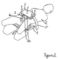
- FIG 2 is the patient (2) from a compared to figure 1 another perspective shown schematically lying.
- an adjustment device (5) is shown.
- a standard receiving coil element (1) is fitted underneath the patient, on which the patient rests with the lower back region and the rear part.
- the coil element (3) according to the invention is located directly on the lower abdominal wall and in the groin area of the patient.
- the two coils (3b) are oriented on the patient's abdomen.
- the third coil (3a) connects, which encloses the penis and scrotum.
- the coils located above the patient are attached to a fixing device (5) which partially circumscribes the patient's torso in the form of an arc. Above the two upper coils (3b), this device is adapted to the shape of the coils.
- Five adjusting screws (6) allow the alignment of the coils (3) relative to the patient (2) to be optimized by means of adjusting devices (not shown).
Description
Die Erfindung bezieht sich auf ein magnetisches Resonanz-tomographisches Gerät für Prostatauntersuchungen an einem darin befindlichen Patienten
gemäß des Oberbegriffs des Anspruchs 1.The invention relates to a magnetic resonance tomographic device for prostate examinations on a patient located therein
according to the preamble of claim 1.
Frühzeitige Erkennung von insbesondere Prostatakrebs ist wichtig für eine erfolgreiche Behandlung. Die normalen Methoden zur Suche nach Prostatakrebs wie manuelle Untersuchungen und Bluttests versagen bei der Auffindung von manchen bösartigen Tumoren oder geben manchmal fälschlicherweise ein positives Testergebnis. Biopsie ist der Weg zur Auffindung eines Tumors und zur Bewertung von dessen Gefährlichkeit. Leider verfehlt diese Biopsie oft den Tumor.Early detection of prostate cancer in particular is important for successful treatment. The normal methods of checking for prostate cancer, such as manual exams and blood tests, fail to detect some malignancies or sometimes give a false positive test result. Biopsy is the way to find a tumor and to assess its dangerousness. Unfortunately, this biopsy often misses the tumor.
Die magnetische Resonanz-Tomographie ist ein bildgebendes Verfahren mit exzellentem Weichteilkontrast, Knochen hingegen werden nicht scharf abgebildet. Deshalb wird es für die Untersuchung der Prostata eingesetzt, wobei eine möglichst gute Auflösung erzielt werden soll.Magnetic resonance tomography is an imaging method with excellent soft-tissue contrast, but bones are not sharply imaged. It is therefore used for examining the prostate, whereby the best possible resolution should be achieved.
Die magnetische Resonanz-Tomographie basiert auf den Prinzipien der Kernspinresonanz (NMR), insbesondere der Feldgradienten-NMR, und wird daher auch als Kernspintomographie bezeichnet. Mit Hilfe der magnetischen Resonanz-Tomographie kann man Schnittbilder des menschlichen (oder tierischen) Körpers anfertigen, die eine Beurteilung der Organe und vieler krankhafter Organveränderungen möglich machen. Die magnetische Resonanz-Tomographie erfordert ein sehr starkes statisches Magnetfeld sowie elektromagnetische Wechselfeldern im Radiofrequenzbereich, mit denen bestimmte Atomkerne (eigentlich immer die Wasserstoffkerne) im Körper resonant angeregt werden, welche dann emittiert und im Empfängerstromkreis elektrische Signale induzieren. Zur Erreichung der Ortsauflösung werden Gradientenspulen verwandt, die zur Erzeugung der magnetischen Gradientenfelder dienen. Die Gradientenspulen werden paarweise mit gleicher Stromstärke aber gegensinniger Polung benutzt, sodass die eine Spule das statische magnetische Feld verringert, die gegenüberliegende Spule hingegen, es um den gleichen Betrag erhöht. Dadurch wird im Ergebnis das magnetische Feld mit einem linearen Gradienten versehen. Für alle drei Raumrichtungen gibt es so eine Vorrichtung. Hintergrund ist, dass das lokale magnetische Feld die Resonanzfrequenz bestimmt und dadurch eine räumliche Lokalisierung möglich macht. Nach dem Stand der Technik werden normalerweise flächige Empfangsspulen verwendet, d.h. mindestens ein flächiges Spulenelement liegt unter dem Rumpf des Patienten und ein flächiges Spulenelement liegt auf dem Patienten. Typischerweise bestehen diese Spulenelemente jeweils aus sechs Spulen, wobei meist zu jeder Spule ein Vorverstärker vorhanden ist. Diese sogenannten Phased-Array Spulen sind eine Kombination von mehreren Oberflächenspulen zu einem Array. Die Idee ist, mit relativ kleinen Spulen, welche ein gutes Signal- zu Rausch-Verhältnis aufweisen, trotzdem ein großes Gebiet abdecken zu können. Das Rauschen setzt sich aus dem thermischen Rauschen des Messobjektes und dem thermischen Rauschen der Hochfrequenzspule zusammen.Magnetic resonance tomography is based on the principles of nuclear magnetic resonance (NMR), in particular field gradient NMR, and is therefore also referred to as nuclear spin tomography. With Magnetic resonance tomography can be used to create sectional images of the human (or animal) body, which make it possible to assess the organs and many pathological organ changes. Magnetic resonance tomography requires a very strong static magnetic field and electromagnetic alternating fields in the radio frequency range, with which certain atomic nuclei (actually always the hydrogen nuclei) in the body are resonantly excited, which then emit and induce electrical signals in the receiver circuit. To achieve spatial resolution, gradient coils are used, which are used to generate the magnetic gradient fields. The gradient coils are used in pairs with the same current but opposite polarity, so that one coil reduces the static magnetic field while the opposite coil increases it by the same amount. As a result, the magnetic field is provided with a linear gradient. There is such a device for all three spatial directions. The background is that the local magnetic field determines the resonance frequency and thus makes spatial localization possible. According to the prior art, flat receiving coils are normally used, ie at least one flat coil element lies under the patient's torso and a flat coil element lies on top of the patient. Typically, these coil elements each consist of six coils, with each coil usually having a preamplifier. These so-called phased array coils are a combination of several surface coils to form an array. The idea is to be able to cover a large area with relatively small coils that have a good signal-to-noise ratio. The noise consists of the thermal noise of the measurement object and the thermal noise of the high-frequency coil.
Jedoch sind diese Empfangsspulen baulich bedingt relativ weit von der Prostata entfernt. Dadurch ist nur eine unzulängliche Auflösung der Prostata gewährleistet. Des Weiteren wird zur Verbesserung der räumlichen Auflösung bereits heute eine sog. Endorektalspule genutzt, die eine bessere räumliche Auflösung der Prostata erlaubt, da hier die Spule in unmittelbarer Nähe zur Prostata positionierbar ist.However, due to their construction, these receiving coils are relatively far away from the prostate. As a result, only insufficient dissolution of the prostate is guaranteed. Furthermore, to improve spatial resolution, a so-called endorectal coil is already used today, which allows better spatial resolution of the prostate, since the coil can be positioned in the immediate vicinity of the prostate.
Die Offenlegungsschrift
Die Offenlegungsschrift
Aufgabe der Erfindung ist es, ein Gerät zu schaffen, bei dem ohne eine Endorektalspule einsetzen zu müssen, dennoch die räumliche Auflösung der Prostata entscheidend erhöht wird.It is the object of the invention to create a device in which the spatial resolution of the prostate is nevertheless decisively increased without having to use an endorectal coil.
Die Lösung dieser Aufgabe besteht darin, dass ein Spulenelement vorgesehen ist, das in drei dreiecksförmig angeordnete Teilspulen unterteilt ist und so eingerichtet ist, dass, wenn sich zwei der Teilspulen parallel nebeneinander auf der unteren Bauchregion des Patienten befinden, eine dritte, geschlossene und mittig angefügte V-förmige Empfangsspule den Hodensack und den Penis umschließt und an den Leisten des Patienten anliegt, wobei Hodensack und Penis eine Öffnung der Empfangsspule durchgreifen.The solution to this problem is that a coil element is provided, which is divided into three triangularly arranged partial coils and is set up in such a way that when two of the partial coils are located parallel to one another on the lower abdominal region of the patient, a third, closed and centrally attached V-shaped receiver coil encloses the scrotum and penis and lies against the patient's groin, with the scrotum and penis passing through an opening in the receiver coil.
Dadurch wird die Spule in unmittelbarer Nähe der Prostata positioniert und erlaubt somit eine bessere räumliche Auflösung, da sie mehr Signal vom Volumenelement Prostata auffangen kann. Diese neuartige Spule wird in Kombination mit einem herkömmlichen flächigen Spulenelement am Rücken des Patienten eingesetzt. Eigentlich müsste man den Patienten von allen Seiten mit Empfangsspulen umgeben, um möglichst viel Signal aufzufangen, d.h. auch seitlich wären Empfangsspulen sinnvoll. Dies ist jedoch aufgrund der unterschiedlichen Anatomie der Körper der Patienten praktisch schlecht umsetzbar. Beim schlanken Patienten wird ein größerer Umfangswinkel vom Standardspulenelement abgedeckt, d.h. die Signalmenge, die verloren geht, ist kleiner, da auch der Abstand zwischen Ober- und Unterseite des Patienten kleiner ist; so wird hier eine bessere Auflösung erreicht. Beim dickeren Patienten ist der vom Standardspulenelement abdeckte Umfangswinkel kleiner, d. h. hier geht mehr Signal seitlich verloren. Folglich ist die Auflösung schlechter als beim schlanken Patienten. Die naheliegende Lösung wäre für unterschiedliche Patienten unterschiedliche Standardspulenelemente vorzusehen, was jedoch nicht praktikabel ist.This places the coil in close proximity to the prostate, allowing better spatial resolution as it can capture more signal from the prostate volume element. This innovative coil is used in combination with a conventional flat coil element on the patient's back. Actually, one would have to surround the patient with receiving coils on all sides in order to pick up as much signal as possible, ie receiving coils on the sides would also be useful. However, due to the different anatomy of the patients' bodies, this is difficult to implement in practice. In the case of the slender patient, a larger circumferential angle is covered by the standard coil element, ie the amount of signal that is lost is less because the distance between the top and bottom of the patient is also smaller; so a better resolution is achieved here. In the case of the thicker patient, the circumferential angle covered by the standard coil element is smaller, ie here more signal is lost laterally. Consequently, the resolution is worse than in the slim patient. The obvious solution would be to provide different standard coil elements for different patients, but this is impractical.
Eine optimale Bildqualität lässt sich dann erreichen, wenn die die Hoden umgebende Empfangsspule mit ihrer Flächennormalen in Richtung der Prostata ausgerichtet ist. Der Begriff "Flächennormale" ist bereits bei ebenen Spulen nicht eindeutig, da eine Vielzahl von parallel zueinander ausgerichteten Flächennormalen existiert. Bei gekrümmten Spulen gilt weiterhin, dass die in den einzelnen Punkten der Fläche senkrecht, also senkrecht zu der dort verlaufenden Tangentialebene definierten Flächennormalen, unterschiedliche Orientierungen aufweisen, soll zur eindeutigen Bestimmung des Verlaufs der Flächennormalen jene ausgewählt werden, die durch den Flächenschwerpunkt der Empfangsspule verläuft, sodass im Ergebnis eine eindeutige Anweisung zum Handeln vorliegt.Optimum image quality can be achieved when the receiving coil surrounding the testicles is aligned with its surface normal in the direction of the prostate. The term "surface normal" is not unambiguous even in the case of flat coils, since there are a large number of surface normals aligned parallel to one another. In the case of curved coils, it also applies that the surface normals defined perpendicularly, i.e. perpendicularly to the tangential plane running there, have different orientations at the individual points of the surface. If the course of the surface normal is to be selected unambiguously, that which runs through the centroid of the receiving coil, so that the result is a clear instruction to act.
Erfindungsgemäß werden oberhalb des Patienten drei Spulen dreiecksförmig angeordnet, d.h. dass zwei Spulen parallel nebeneinander auf dem Bauch des Patienten anliegen und die dritte Spule den Hodensack und den Penis umschließt. Die dritte Spule liegt mit den unteren Längsseiten V-förmig an der rechten und linken Leiste an, sodass der Hodensack und der Penis die Öffnung der Spule durchgreifen. Durch das Spreizen der Oberschenkel und mit leichtem Andruck der Spule bekommt man eine optimale Ausrichtung des Spulenelementes. Die beiden oberen Spulenelemente befinden sich zwischen der Leiste und der unteren Bauchdecke und können mit ihrer Flächennormale in Richtung Prostata ausgerichtet sein.According to the invention, three coils are arranged in a triangular shape above the patient, ie two coils lie parallel to one another on the patient's stomach and the third coil encloses the scrotum and the penis. The lower longitudinal sides of the third coil lie in a V-shape on the right and left groin, so that the scrotum and the penis reach through the opening of the coil. By spreading your thighs and applying slight pressure on the coil, you get an optimal alignment of the coil element. The two upper coil elements are located between the groin and the lower abdominal wall and can be aligned with their surface normal in the direction of the prostate.
Gem. einer Alternativen kann die magnetische Resonanz-Tomographie-Spule auch aus mehr als drei Spulen an der Oberseite des Patienten aufgebaut sein. Dadurch kann das Auflösungsvermögen erhöht werden, da das Signal- zu Rausch-Verhältnis bei kleineren Spulen günstiger wird. Die Anzahl der Spulen definiert in ihrer Gesamtheit jene Fläche, in der Signale erfasst und damit auch ausgewertet werden können. Dabei bestimmt die äußere Umrandung dieser Fläche die sich als Summe der Flächen der einzelnen Spulen addiert, die Eindringtiefe der gesamten Anordnung, die aus allen Spulen gebildet wird. Werden mehrere Spulen zusammen und gleichzeitig eingesetzt, erhält man ein Messergebnis, bei dem die hohe Empfindlichkeit der einzelnen Spule zum einen und die hohe Eindringtiefe der gesamten Anordnung zum anderen kombiniert werden.According to an alternative, the magnetic resonance tomography coil can also be constructed from more than three coils on the upper side of the patient. As a result, the resolution can be increased since the signal-to-noise ratio is more favorable with smaller coils. The total number of coils defines the area in which signals can be recorded and thus also evaluated. The outer border of this area, which adds up as the sum of the areas of the individual coils, determines the penetration depth of the entire arrangement, which is formed from all the coils. If several coils are used together and at the same time, a measurement result is obtained in which the high sensitivity of the individual coils on the one hand and the high penetration depth of the entire arrangement on the other are combined.
Die relative Zuordnung der Spulen ist im Rahmen der Erfindung grundsätzlich beliebig. So können die Spulen zueinander beabstandet sein, was durch bauliche Zwänge geboten sein kann. Als nachteilig ist anzusehen, dass die in Zwischenräume der Spule emittierten Signale nicht genutzt werden können.The relative assignment of the coils is fundamentally arbitrary within the scope of the invention. The coils can be spaced apart from one another, which may be required by structural constraints. The disadvantage is that the signals emitted in the spaces between the coils cannot be used.
In einem bevorzugten Fall schließen die Spulen direkt aneinander an, was den Vorteil hat, dass möglichst wenig emittierte Signale verloren gehen. Je höher die empfangene Intensität der Signale, desto besser wird die Bildqualität.In a preferred case, the coils connect directly to one another, which has the advantage that as few emitted signals as possible are lost. The higher the received signal intensity, the better the image quality.
Das Auflegen und Entfernen wird stark vereinfacht, wenn die Spulen in einer flexibeln Matte untergebracht sind. Dies hat den Vorteil, dass sich diese Matte weitgehend der individuellen Körperform des Patienten anpasst. Damit liegen die Empfangsspulen möglichst dicht am Patienten an und erlauben somit eine bessere Bildqualität. Ein Durchgriff für Penis und Hodensack muss in der Matte vorhanden sein.Loading and unloading is greatly simplified when the coils are housed in a flexible mat. This has the advantage that this mat largely adapts to the individual body shape of the patient. This means that the receiving coils are as close as possible to the patient and thus allow better image quality. A Access for the penis and scrotum must be available in the mat.
Ziel ist es, das die Prostata umgebende und darstellende Volumenelement scharf abzubilden. Zur Optimierung ist der Radius der Empfangsspule so gewählt, dass er größer oder gleich dem durchschnittlichen Abstand der Spulenebene zum zu untersuchenden Organ, hier der Prostata, ist.The aim is to sharply image the volume element surrounding and representing the prostate. For optimization, the radius of the receiving coil is selected so that it is greater than or equal to the average distance between the coil plane and the organ to be examined, in this case the prostate.
Der Abstand variiert von Patient zu Patient, deshalb wird hier der Begriff "durchschnittlicher Abstand" als Mittelwert der anatomischen Gegebenheiten beschrieben. Die Eindringtiefe hängt direkt vom Spulenradius ab. Die Auflösung ist optimal, wenn die Entfernung des zu untersuchenden Organs von der Spulenebene maximal dem Radius der Spule entspricht. Grundsätzlich gilt, dass die Bildqualität umso besser wird, je geringer der Abstand Spule-Prostata ist.The distance varies from patient to patient, therefore the term "average distance" is described here as the average of the anatomical conditions. The penetration depth depends directly on the coil radius. The resolution is optimal when the distance of the organ to be examined from the plane of the coil corresponds at most to the radius of the coil. Basically, the smaller the distance between the coil and the prostate, the better the image quality.
Es wurde als empfehlenswert erkannt, während der Aufnahmephase den Patienten im Bereich des Bauches oder Rumpfes zumindest mit einer diese teilweise umschließende Fixiereinrichtung räumlich zu positionieren. Der Patient wird dann mit Hilfe eines Korsetts festgehalten, sodass keine zu Unschärfen der Aufnahme Anlass gebenden Bewegungen möglich sind. Durch die Fixierung erreicht man eine bessere Bildqualität, da die Bewegung des Patienten eingeschränkt ist und weniger Bewegungsartefakte auftreten können.It was found to be advisable during the recording phase to spatially position the patient in the area of the stomach or trunk at least with a fixation device that partially encloses the latter. The patient is then held in place with the help of a corset, so that no movements that would cause blurring of the recording are possible. The fixation achieves a better image quality since the patient's movement is restricted and fewer movement artifacts can occur.
Schließlich wird vorgeschlagen, die Empfangsspulen über Justiereinrichtungen zu befestigen, die es in der praktischen Anwendung erlauben, die Empfangsspulen optimal auszurichten, um dem zu Folge auch eine bessere Bildqualität zu erzielen. Eine ausdrücklich empfehlenswerte Möglichkeit besteht darin, die Justiereinrichtungen an der Fixiereinrichtung zu befestigen.Finally, it is proposed to fasten the receiving coils using adjustment devices which, in practical use, allow the receiving coils to be optimally aligned in order to also achieve better image quality as a result. An option that is expressly recommended is to attach the adjustment devices to the fixing device.
In einer vorteilhaften Ausgestaltung wird ein keilförmiges Kissen eingesetzt, das unterhalb des Beckens des Patienten derart eingeschoben wird, dass das Becken leicht nach oben gekippt, was ein Einschieben der Keilspitze in Richtung der Längsachse des Patienten erfordert. Dieses Kissen dient der Ausrichtung des Beckens und damit der Ausrichtung der Prostata zur Empfangsspule. Durch eine optimale Ausrichtung kann eine bessere Bildqualität erreicht werden.In an advantageous embodiment, a wedge-shaped cushion is used, which is inserted below the patient's pelvis in such a way that the pelvis tilts slightly upwards, which requires the tip of the wedge to be inserted in the direction of the longitudinal axis of the patient. This cushion is used to align the pelvis and thus the alignment of the prostate to the receiving coil. Better image quality can be achieved with optimal alignment.
In einer Weiterbildung wird ein Kissen verwandt, das mit Flüssigkeit oder Gas beaufschlagt werden kann, um somit die Form des Kissens zu ändern und damit die Ausrichtung des Beckens des Patienten zu optimieren. Durch eine entsprechende Beaufschlagung des Kissens lassen sich in infinitesimalen Schritten und in weiten Grenzen eine beliebige Ausrichtung des Beckens realisieren.In a development, a cushion is used that can be charged with liquid or gas in order to change the shape of the cushion and thus optimize the alignment of the patient's pelvis. Any adjustment of the pelvis can be achieved in infinitesimal steps and within wide limits by applying pressure to the cushion accordingly.
In einer Ausführungsform kann das Kissen in mehrere Sektoren bzw. Kammern unterteilt sein, welche unterschiedlich mit Gas oder Flüssigkeit beaufschlagt werden können. Wird eine Kammer mit höherem Druck beaufschlagt, vergrößert sie sich, bei geringerem Druck ist die jeweilige Kammer kleiner. Dies hat den Vorteil, dass man zielgenau das Becken des Patienten in unterschiedlichen Raumrichtungen ausrichten kann, indem man die einzelnen Kammern individuell beaufschlagt und damit einstellt. Die Anzahl der Sektoren bzw. Kammern entspricht der Anzahl der Einstellungsparametern, die zur Verfügung stehen.In one embodiment, the cushion can be divided into a number of sectors or chambers, which can be charged with gas or liquid in different ways. If a chamber is pressurized with higher pressure, it enlarges, with lower pressure the respective chamber is smaller. This has the advantage that the patient's pelvis can be precisely aligned in different spatial directions by individually loading and adjusting the individual chambers. The number of sectors or chambers corresponds to the number of setting parameters that are available.
Ziel ist auch hier die Bildqualität zu verbessern.The aim here is also to improve the image quality.
Schließlich können auf oder in diesem Kissen auch Empfangsspulen untergebracht sein. Das Verbauen der Empfangsspulen direkt auf oder im Kissen erlaubt eine nähere Platzierung am Patienten, damit verbunden ist eine höhere Auflösung und ein besseres Signal- zu Rausch-Verhältnis.Finally, receiving coils can also be accommodated on or in this cushion. Installing the receiving coils directly on or in the pillow allows them to be placed closer to the patient, connected is a higher resolution and a better signal-to-noise ratio.
In einer weiteren Ausgestaltung können für jede Spule elektrische Vorverstärker verbaut sein, um das Signal möglichst schon an der Spule zu verstärken. Dadurch wird die zusätzliche relative Rauschamplitude durch die Leitungen zur Elektronik des magnetischen Resonanz-tomographischen Gerätes kleiner, damit die Signalqualität besser und schließlich auch die Bildqualität.In a further embodiment, electrical preamplifiers can be installed for each coil in order to amplify the signal as early as possible at the coil. As a result, the additional relative noise amplitude through the lines to the electronics of the magnetic resonance tomography device becomes smaller, thus improving the signal quality and ultimately also the image quality.
Im Folgenden soll die Erfindung an Hand von der in der Zeichnung darstellten Ausführungsformen näher beschrieben werden. Es zeigen in prinzipienhaft gehaltenen Darstellungen:
- Figur 1:
- ein erfindungsgemäßes Spulenelement mit Patienten in Ansicht
- Figur 2:
- Spulenelement mit Patienten sowie eine Fixiereinrichtung
- Figure 1:
- an inventive coil element with patients in view
- Figure 2:
- Coil element with patient and a fixation device
In der 3D-Darstellung der
Auf der unteren Bauchregion und auf dem Leistenbereich des Patienten befindet sich das erfindungsgemäße Spulenelement (3). Dieses ist in drei Teilspulen unterteilt, die dreiecksförmig angeordnet sind. Zwei Spulen (3b) befinden sich parallel nebeneinander auf der unteren Bauchregion des Patienten und sind mit ihrer Flächennormale in Richtung Prostata ausgerichtet. Eine dritte Spule (3a), die in Zusammenhang mit der Erfindung von entscheidender Bedeutung ist, wurde unten an diese zwei Spulen (3b) mittig angefügt, sodass sie Hodensack und Penis umschließt und an den Leisten des Patienten anliegt, wenn dieser die Oberschenkel leicht spreizt. Diese dritte Spule (3a) ist V-förmig gestaltet und ebenfalls mit ihrer Flächennormale in Richtung Prostata ausgerichtet. Die ebenfalls eingezeichnete Biopsieeinrichtung (4) spielt keine Rolle für die Erfindung. Nicht eingezeichnet ist das eigentliche magnetische Resonanztomographische Gerät, d. h. die das starke homogene Magnetfeld erzeugende Spule sowie die Sendespule. Auch nicht dargestellt sind die Gradientenspulen.The coil element (3) according to the invention is located on the lower abdominal region and on the groin area of the patient. This is divided into three sub-coils arranged in a triangular shape are. Two coils (3b) are located parallel to one another on the patient's lower abdominal region and are aligned with their surface normal in the direction of the prostate. A third coil (3a), which is of crucial importance in the context of the invention, has been added at the bottom of these two coils (3b) centrally so that it encloses the scrotum and penis and rests against the patient's groin when the thighs are spread slightly . This third coil (3a) is V-shaped and is also aligned with its surface normal in the direction of the prostate. The biopsy device (4), which is also shown, plays no role in the invention. The actual magnetic resonance tomographic device is not shown, ie the coil generating the strong homogeneous magnetic field and the transmitting coil. The gradient coils are also not shown.
In
In allen zeichnerischen Darstellungen werden aus Gründen der Klarheit funktionswesentliche Geräteelemente nicht dargestellt. Hierzu zählen die homogene Spule, die Gradientenspulen sowie die zur Auswertung notwendige Datenverarbeitungsanlage.Functionally essential device elements are not shown in any of the drawings for reasons of clarity. These include the homogeneous coil, the gradient coils and the data processing system required for evaluation.
- 1 Standardspulenelement1 standard coil element
- 2 Patient2 patient
- 3 Spulen3 coils
- 3a Empfangsspule3a receiving coil
- 3b Spulen3b coils
- 4 Biopsieeinrichtung4 biopsy device
- 5 Fixiereinrichtung5 fixing device
- 6 Justierschrauben6 adjustment screws
Claims (14)
- Magnetic resonance tomographic device for prostate examinations on a patient (2) located therein, consisting of a coil for generating a strong homogeneous magnetic field in the direction of the longitudinal axis of the patient, at least one transmission coil for generating an electromagnetic alternating field, three gradient coils and suitable receiving coils (1), of which some are to be arranged below in the lower back region and/or on the rear and at least three are to be arranged above the patient, as well as data processing for image acquisition from the signals of the transmission and receiving coils, wherein a coil element (3) is provided, which is divided into three triangularly arranged sub-coils (3a, 3b) and is set up in such a way that when two of the sub-coils (3b) are located parallel to one another on the lower abdominal region of the patient, a third, closed and centrally attached V-shaped receiving coil (3a) encloses the scrotum and the penis and rests against the patient's groins, with the scrotum and penis reaching through an opening in the receiving coil (3a).
- Magnetic resonance tomographic device according to claim 1, characterized in that the receiving coil (3a) enclosing the scrotum and/or the sub-coils (3b) are, with their surface normal going through respective center of area, pointing in the direction of the prostate.
- Magnetic resonance tomographic device according to claim 1 or 2, characterized in that more than three coils are arranged on the patient.
- Magnetic resonance tomographic device according to one of the preceding claims, characterized in that the coils are distanced from one another.
- Magnetic resonance tomographic device according to one of the claims 1 - 3, characterized in that the coils are immediately adjacent to one another.
- Magnetic resonance tomographic device according to one of the preceding claims, characterized in that the coils are housed in a flexible mat which lies on the patient.
- Magnetic resonance tomographic device according to one of the preceding claims, characterized in that the radius of the coils is larger or equal the average distance between the coil plane and the prostate.
- Magnetic resonance tomographic device according to one of the preceding claims, characterized in that a fixing device arcuately encloses stomach, torso of the patient at least partially.
- Magnetic resonance tomographic device according to one of the preceding claims, characterized in that the receiving coil is attached via an adjustment device.
- Magnetic resonance tomographic device according to one of the preceding claims, characterized in that a wedge-shape cushion is arranged below the pelvis of the patient.
- Magnetic resonance tomographic device according to claim 10, characterized in that a cushion which can be filled with liquid or gas, is arranged below the pelvis of the patient.
- Magnetic resonance tomographic device according to claim 11, characterized in that the cushion is subdevided into several sections/chambers, which can be filled with liquid or gas differently.
- Magnetic resonance tomographic device according to one of the claims 10 to 12, characterized in that on or in the cushion receiving coils are installed.
- Magnetic resonance tomographic device according to claim 1-6 and 12, characterized in that a pre-amplifier is present for each coil.
Applications Claiming Priority (2)
| Application Number | Priority Date | Filing Date | Title |
|---|---|---|---|
| DE102012022779.5A DE102012022779A1 (en) | 2012-11-22 | 2012-11-22 | Magnetic resonance tomographic device |
| PCT/DE2013/100386 WO2014079416A1 (en) | 2012-11-22 | 2013-11-15 | Coil arrangement for a magnetic resonance imaging device |
Publications (2)
| Publication Number | Publication Date |
|---|---|
| EP2922467A1 EP2922467A1 (en) | 2015-09-30 |
| EP2922467B1 true EP2922467B1 (en) | 2022-10-26 |
Family
ID=49765747
Family Applications (1)
| Application Number | Title | Priority Date | Filing Date |
|---|---|---|---|
| EP13805746.8A Active EP2922467B1 (en) | 2012-11-22 | 2013-11-15 | Coil arrangement for a magnetic resonance imaging device |
Country Status (6)
| Country | Link |
|---|---|
| US (1) | US9913597B2 (en) |
| EP (1) | EP2922467B1 (en) |
| CN (1) | CN104822318B (en) |
| CA (1) | CA2891369C (en) |
| DE (2) | DE102012022779A1 (en) |
| WO (1) | WO2014079416A1 (en) |
Families Citing this family (5)
| Publication number | Priority date | Publication date | Assignee | Title |
|---|---|---|---|---|
| US11039787B2 (en) | 2011-11-23 | 2021-06-22 | Scanmed, Llc | Garment MRI antenna array |
| CN106680745B (en) * | 2017-02-24 | 2023-03-10 | 深圳市金石医疗科技有限公司 | Magnetic resonance imaging system |
| JP1623846S (en) | 2017-10-27 | 2019-02-04 | ||
| USD911526S1 (en) | 2018-05-21 | 2021-02-23 | Scanmed, Llc | Pelvic MRI coil |
| CN114176879A (en) * | 2021-11-29 | 2022-03-15 | 天津医科大学第二医院 | Male penis position magnetic resonance imaging integrated coil with erection assisting function |
Family Cites Families (6)
| Publication number | Priority date | Publication date | Assignee | Title |
|---|---|---|---|---|
| DE10317629B8 (en) * | 2002-04-17 | 2010-03-04 | Ge Medical Systems Global Technology Company Llc, Waukesha | RF coil and magnetic resonance imaging device |
| DE10221644A1 (en) * | 2002-05-15 | 2003-12-11 | Siemens Ag | Magnetic resonance local coil arrangement for prostrate and cervical carcinoma examinations comprises a trouser like support for the coil arrangement so that the coil is simply positioned by pulling the trousers on |
| US7940047B2 (en) * | 2007-11-23 | 2011-05-10 | Sentinelle Medical, Inc. | Microcontroller system for identifying RF coils in the bore of a magnetic resonance imaging system |
| GB0905769D0 (en) * | 2009-04-03 | 2009-05-20 | Siemens Ag | Microwave connection |
| DE102011075440B4 (en) * | 2011-05-06 | 2014-05-22 | Siemens Aktiengesellschaft | Head support cushion with integrated patient fixation |
| EP2859372A1 (en) * | 2012-06-07 | 2015-04-15 | Koninklijke Philips N.V. | Non-invasive prostate coil for mr systems with vertical main field |
-
2012
- 2012-11-22 DE DE102012022779.5A patent/DE102012022779A1/en not_active Withdrawn
-
2013
- 2013-11-15 DE DE112013005596.1T patent/DE112013005596A5/en not_active Withdrawn
- 2013-11-15 CA CA2891369A patent/CA2891369C/en not_active Expired - Fee Related
- 2013-11-15 CN CN201380060533.2A patent/CN104822318B/en not_active Expired - Fee Related
- 2013-11-15 EP EP13805746.8A patent/EP2922467B1/en active Active
- 2013-11-15 US US14/646,056 patent/US9913597B2/en not_active Expired - Fee Related
- 2013-11-15 WO PCT/DE2013/100386 patent/WO2014079416A1/en active Application Filing
Also Published As
| Publication number | Publication date |
|---|---|
| CN104822318A (en) | 2015-08-05 |
| CA2891369C (en) | 2020-09-29 |
| US9913597B2 (en) | 2018-03-13 |
| EP2922467A1 (en) | 2015-09-30 |
| CN104822318B (en) | 2018-02-27 |
| DE102012022779A1 (en) | 2014-05-22 |
| DE112013005596A5 (en) | 2015-10-22 |
| US20150305647A1 (en) | 2015-10-29 |
| WO2014079416A1 (en) | 2014-05-30 |
| CA2891369A1 (en) | 2014-05-30 |
Similar Documents
| Publication | Publication Date | Title |
|---|---|---|
| EP2922467B1 (en) | Coil arrangement for a magnetic resonance imaging device | |
| DE60221781T2 (en) | Wireless position sensor | |
| DE102007054324B4 (en) | Device for radiotherapy under image monitoring | |
| DE102009021232B4 (en) | Patient couch, method for a patient couch and imaging medical device | |
| DE102007013564B4 (en) | Method and device for automatic determination of radiation-attenuating objects by means of a magnetic resonance system | |
| DE102007030568A1 (en) | Couch device with a local antenna device for a magnetic resonance device | |
| EP1021730A1 (en) | Mr imaging method and medical device for use in method | |
| DE102013206055A1 (en) | Method and local coil system for generating a magnetic resonance high-frequency field | |
| DE69822709T2 (en) | Open magnet for magnetic resonance imaging with inhomogeneous field | |
| DE102011079577A1 (en) | Oral coil of radio frequency receiver for magnetic resonance imaging system for generating magnetic resonance image of jaw region of patient, has shim elements for homogenization of static magnetic field | |
| DE102015205694B3 (en) | MR saturation taking into account the anatomical structures to be imaged | |
| DE102013226745A1 (en) | Magnetic resonance scanning device for medical diagnostics | |
| DE69432605T2 (en) | MAGNETIC RESONANCE DISPLAY DEVICE FOR TOOLING | |
| EP3073913B1 (en) | Patient table for establishing nmr recordings and/or ct recordings | |
| DE102013214880A1 (en) | magnetic resonance apparatus | |
| EP3223699B1 (en) | Patient examination table for a nuclear resonance tomography examination | |
| DE102014204381B4 (en) | Planning a brachytherapy treatment based on magnetic resonance image data with hyperintense areas | |
| DE102011054832B3 (en) | High frequency MRI local coil device for MRI-controlled high-intensity focused ultrasound treatment of prostate carcinoma in e.g. human patient, has cuffs comprising openings, where device comprises locating units for instrument | |
| DE69632349T2 (en) | RF coil arrangement for magnetic resonance | |
| DE102006054599B3 (en) | Analysis area's core spin selective excitation method, involves selecting orientation of layer-selective magnetic field gradients based on relative layer of analysis area at structure, such excitation area lies far away from structure | |
| DE102012217439A1 (en) | Patient couch for combined magnetic resonance and PET examination | |
| DE10340002B3 (en) | Positioning device for positioning a patient | |
| DE102015224969A1 (en) | Adjustable shoulder coil | |
| DE102009012851A1 (en) | Method, magnetic resonance apparatus, computer program product and electronically readable data carrier for obtaining a first image data record and a second image data record of an examination subject | |
| DE10322141A1 (en) | Adaptation of magnetic resonance metrology record to investigated object, by analyzing measuring data to determine geometric parameters to describe the maximum expansion of the object in each measured dimension |
Legal Events
| Date | Code | Title | Description |
|---|---|---|---|
| PUAI | Public reference made under article 153(3) epc to a published international application that has entered the european phase |
Free format text: ORIGINAL CODE: 0009012 |
|
| 17P | Request for examination filed |
Effective date: 20150507 |
|
| AK | Designated contracting states |
Kind code of ref document: A1 Designated state(s): AL AT BE BG CH CY CZ DE DK EE ES FI FR GB GR HR HU IE IS IT LI LT LU LV MC MK MT NL NO PL PT RO RS SE SI SK SM TR |
|
| AX | Request for extension of the european patent |
Extension state: BA ME |
|
| DAX | Request for extension of the european patent (deleted) | ||
| STAA | Information on the status of an ep patent application or granted ep patent |
Free format text: STATUS: EXAMINATION IS IN PROGRESS |
|
| 17Q | First examination report despatched |
Effective date: 20191210 |
|
| STAA | Information on the status of an ep patent application or granted ep patent |
Free format text: STATUS: EXAMINATION IS IN PROGRESS |
|
| GRAP | Despatch of communication of intention to grant a patent |
Free format text: ORIGINAL CODE: EPIDOSNIGR1 |
|
| STAA | Information on the status of an ep patent application or granted ep patent |
Free format text: STATUS: GRANT OF PATENT IS INTENDED |
|
| INTG | Intention to grant announced |
Effective date: 20220520 |
|
| GRAS | Grant fee paid |
Free format text: ORIGINAL CODE: EPIDOSNIGR3 |
|
| GRAA | (expected) grant |
Free format text: ORIGINAL CODE: 0009210 |
|
| STAA | Information on the status of an ep patent application or granted ep patent |
Free format text: STATUS: THE PATENT HAS BEEN GRANTED |
|
| AK | Designated contracting states |
Kind code of ref document: B1 Designated state(s): AL AT BE BG CH CY CZ DE DK EE ES FI FR GB GR HR HU IE IS IT LI LT LU LV MC MK MT NL NO PL PT RO RS SE SI SK SM TR |
|
| REG | Reference to a national code |
Ref country code: GB Ref legal event code: FG4D Free format text: NOT ENGLISH |
|
| REG | Reference to a national code |
Ref country code: CH Ref legal event code: EP |
|
| REG | Reference to a national code |
Ref country code: DE Ref legal event code: R096 Ref document number: 502013016272 Country of ref document: DE |
|
| REG | Reference to a national code |
Ref country code: AT Ref legal event code: REF Ref document number: 1526459 Country of ref document: AT Kind code of ref document: T Effective date: 20221115 |
|
| REG | Reference to a national code |
Ref country code: IE Ref legal event code: FG4D Free format text: LANGUAGE OF EP DOCUMENT: GERMAN |
|
| PGFP | Annual fee paid to national office [announced via postgrant information from national office to epo] |
Ref country code: GB Payment date: 20221129 Year of fee payment: 10 Ref country code: FR Payment date: 20221121 Year of fee payment: 10 Ref country code: DE Payment date: 20221117 Year of fee payment: 10 Ref country code: AT Payment date: 20221207 Year of fee payment: 10 |
|
| REG | Reference to a national code |
Ref country code: LT Ref legal event code: MG9D |
|
| PGFP | Annual fee paid to national office [announced via postgrant information from national office to epo] |
Ref country code: BE Payment date: 20221207 Year of fee payment: 10 |
|
| REG | Reference to a national code |
Ref country code: NL Ref legal event code: MP Effective date: 20221026 |
|
| PG25 | Lapsed in a contracting state [announced via postgrant information from national office to epo] |
Ref country code: NL Free format text: LAPSE BECAUSE OF FAILURE TO SUBMIT A TRANSLATION OF THE DESCRIPTION OR TO PAY THE FEE WITHIN THE PRESCRIBED TIME-LIMIT Effective date: 20221026 |
|
| PG25 | Lapsed in a contracting state [announced via postgrant information from national office to epo] |
Ref country code: SE Free format text: LAPSE BECAUSE OF FAILURE TO SUBMIT A TRANSLATION OF THE DESCRIPTION OR TO PAY THE FEE WITHIN THE PRESCRIBED TIME-LIMIT Effective date: 20221026 Ref country code: PT Free format text: LAPSE BECAUSE OF FAILURE TO SUBMIT A TRANSLATION OF THE DESCRIPTION OR TO PAY THE FEE WITHIN THE PRESCRIBED TIME-LIMIT Effective date: 20230227 Ref country code: NO Free format text: LAPSE BECAUSE OF FAILURE TO SUBMIT A TRANSLATION OF THE DESCRIPTION OR TO PAY THE FEE WITHIN THE PRESCRIBED TIME-LIMIT Effective date: 20230126 Ref country code: LT Free format text: LAPSE BECAUSE OF FAILURE TO SUBMIT A TRANSLATION OF THE DESCRIPTION OR TO PAY THE FEE WITHIN THE PRESCRIBED TIME-LIMIT Effective date: 20221026 Ref country code: FI Free format text: LAPSE BECAUSE OF FAILURE TO SUBMIT A TRANSLATION OF THE DESCRIPTION OR TO PAY THE FEE WITHIN THE PRESCRIBED TIME-LIMIT Effective date: 20221026 Ref country code: ES Free format text: LAPSE BECAUSE OF FAILURE TO SUBMIT A TRANSLATION OF THE DESCRIPTION OR TO PAY THE FEE WITHIN THE PRESCRIBED TIME-LIMIT Effective date: 20221026 |
|
| PG25 | Lapsed in a contracting state [announced via postgrant information from national office to epo] |
Ref country code: RS Free format text: LAPSE BECAUSE OF FAILURE TO SUBMIT A TRANSLATION OF THE DESCRIPTION OR TO PAY THE FEE WITHIN THE PRESCRIBED TIME-LIMIT Effective date: 20221026 Ref country code: PL Free format text: LAPSE BECAUSE OF FAILURE TO SUBMIT A TRANSLATION OF THE DESCRIPTION OR TO PAY THE FEE WITHIN THE PRESCRIBED TIME-LIMIT Effective date: 20221026 Ref country code: LV Free format text: LAPSE BECAUSE OF FAILURE TO SUBMIT A TRANSLATION OF THE DESCRIPTION OR TO PAY THE FEE WITHIN THE PRESCRIBED TIME-LIMIT Effective date: 20221026 Ref country code: IS Free format text: LAPSE BECAUSE OF FAILURE TO SUBMIT A TRANSLATION OF THE DESCRIPTION OR TO PAY THE FEE WITHIN THE PRESCRIBED TIME-LIMIT Effective date: 20230226 Ref country code: HR Free format text: LAPSE BECAUSE OF FAILURE TO SUBMIT A TRANSLATION OF THE DESCRIPTION OR TO PAY THE FEE WITHIN THE PRESCRIBED TIME-LIMIT Effective date: 20221026 Ref country code: GR Free format text: LAPSE BECAUSE OF FAILURE TO SUBMIT A TRANSLATION OF THE DESCRIPTION OR TO PAY THE FEE WITHIN THE PRESCRIBED TIME-LIMIT Effective date: 20230127 |
|
| REG | Reference to a national code |
Ref country code: CH Ref legal event code: PL |
|
| REG | Reference to a national code |
Ref country code: DE Ref legal event code: R097 Ref document number: 502013016272 Country of ref document: DE |
|
| PG25 | Lapsed in a contracting state [announced via postgrant information from national office to epo] |
Ref country code: SM Free format text: LAPSE BECAUSE OF FAILURE TO SUBMIT A TRANSLATION OF THE DESCRIPTION OR TO PAY THE FEE WITHIN THE PRESCRIBED TIME-LIMIT Effective date: 20221026 Ref country code: RO Free format text: LAPSE BECAUSE OF FAILURE TO SUBMIT A TRANSLATION OF THE DESCRIPTION OR TO PAY THE FEE WITHIN THE PRESCRIBED TIME-LIMIT Effective date: 20221026 Ref country code: MC Free format text: LAPSE BECAUSE OF FAILURE TO SUBMIT A TRANSLATION OF THE DESCRIPTION OR TO PAY THE FEE WITHIN THE PRESCRIBED TIME-LIMIT Effective date: 20221026 Ref country code: LI Free format text: LAPSE BECAUSE OF NON-PAYMENT OF DUE FEES Effective date: 20221130 Ref country code: EE Free format text: LAPSE BECAUSE OF FAILURE TO SUBMIT A TRANSLATION OF THE DESCRIPTION OR TO PAY THE FEE WITHIN THE PRESCRIBED TIME-LIMIT Effective date: 20221026 Ref country code: DK Free format text: LAPSE BECAUSE OF FAILURE TO SUBMIT A TRANSLATION OF THE DESCRIPTION OR TO PAY THE FEE WITHIN THE PRESCRIBED TIME-LIMIT Effective date: 20221026 Ref country code: CZ Free format text: LAPSE BECAUSE OF FAILURE TO SUBMIT A TRANSLATION OF THE DESCRIPTION OR TO PAY THE FEE WITHIN THE PRESCRIBED TIME-LIMIT Effective date: 20221026 Ref country code: CH Free format text: LAPSE BECAUSE OF NON-PAYMENT OF DUE FEES Effective date: 20221130 |
|
| PG25 | Lapsed in a contracting state [announced via postgrant information from national office to epo] |
Ref country code: SK Free format text: LAPSE BECAUSE OF FAILURE TO SUBMIT A TRANSLATION OF THE DESCRIPTION OR TO PAY THE FEE WITHIN THE PRESCRIBED TIME-LIMIT Effective date: 20221026 Ref country code: LU Free format text: LAPSE BECAUSE OF NON-PAYMENT OF DUE FEES Effective date: 20221115 Ref country code: AL Free format text: LAPSE BECAUSE OF FAILURE TO SUBMIT A TRANSLATION OF THE DESCRIPTION OR TO PAY THE FEE WITHIN THE PRESCRIBED TIME-LIMIT Effective date: 20221026 |
|
| PLBE | No opposition filed within time limit |
Free format text: ORIGINAL CODE: 0009261 |
|
| STAA | Information on the status of an ep patent application or granted ep patent |
Free format text: STATUS: NO OPPOSITION FILED WITHIN TIME LIMIT |
|
| 26N | No opposition filed |
Effective date: 20230727 |
|
| PG25 | Lapsed in a contracting state [announced via postgrant information from national office to epo] |
Ref country code: IE Free format text: LAPSE BECAUSE OF NON-PAYMENT OF DUE FEES Effective date: 20221115 |
|
| PG25 | Lapsed in a contracting state [announced via postgrant information from national office to epo] |
Ref country code: SI Free format text: LAPSE BECAUSE OF FAILURE TO SUBMIT A TRANSLATION OF THE DESCRIPTION OR TO PAY THE FEE WITHIN THE PRESCRIBED TIME-LIMIT Effective date: 20221026 |
|
| PG25 | Lapsed in a contracting state [announced via postgrant information from national office to epo] |
Ref country code: HU Free format text: LAPSE BECAUSE OF FAILURE TO SUBMIT A TRANSLATION OF THE DESCRIPTION OR TO PAY THE FEE WITHIN THE PRESCRIBED TIME-LIMIT; INVALID AB INITIO Effective date: 20131115 |