EP2922129A1 - Fuell cell system - Google Patents
Fuell cell system Download PDFInfo
- Publication number
- EP2922129A1 EP2922129A1 EP15159188.0A EP15159188A EP2922129A1 EP 2922129 A1 EP2922129 A1 EP 2922129A1 EP 15159188 A EP15159188 A EP 15159188A EP 2922129 A1 EP2922129 A1 EP 2922129A1
- Authority
- EP
- European Patent Office
- Prior art keywords
- water
- storage water
- water circulation
- fuel cell
- heat exchanger
- Prior art date
- Legal status (The legal status is an assumption and is not a legal conclusion. Google has not performed a legal analysis and makes no representation as to the accuracy of the status listed.)
- Granted
Links
- XLYOFNOQVPJJNP-UHFFFAOYSA-N water Substances O XLYOFNOQVPJJNP-UHFFFAOYSA-N 0.000 claims abstract description 447
- 229910001868 water Inorganic materials 0.000 claims abstract description 433
- 239000000446 fuel Substances 0.000 claims abstract description 157
- 238000001514 detection method Methods 0.000 claims abstract description 58
- 239000000567 combustion gas Substances 0.000 claims abstract description 52
- 238000010248 power generation Methods 0.000 claims abstract description 24
- 230000007423 decrease Effects 0.000 claims description 29
- 238000003487 electrochemical reaction Methods 0.000 claims description 5
- 238000010326 electrochemical discharging Methods 0.000 claims description 4
- 238000011144 upstream manufacturing Methods 0.000 claims description 4
- 238000007599 discharging Methods 0.000 abstract description 2
- 239000007789 gas Substances 0.000 description 61
- 238000002485 combustion reaction Methods 0.000 description 35
- 238000001704 evaporation Methods 0.000 description 23
- 230000003197 catalytic effect Effects 0.000 description 20
- 239000003054 catalyst Substances 0.000 description 19
- VNWKTOKETHGBQD-UHFFFAOYSA-N methane Chemical compound C VNWKTOKETHGBQD-UHFFFAOYSA-N 0.000 description 16
- 238000002407 reforming Methods 0.000 description 16
- 238000009833 condensation Methods 0.000 description 13
- 230000005494 condensation Effects 0.000 description 13
- 238000010438 heat treatment Methods 0.000 description 13
- 230000008021 deposition Effects 0.000 description 12
- 239000000463 material Substances 0.000 description 12
- 239000000126 substance Substances 0.000 description 9
- 238000006243 chemical reaction Methods 0.000 description 8
- UGFAIRIUMAVXCW-UHFFFAOYSA-N Carbon monoxide Chemical compound [O+]#[C-] UGFAIRIUMAVXCW-UHFFFAOYSA-N 0.000 description 7
- 229910002091 carbon monoxide Inorganic materials 0.000 description 7
- 229910052739 hydrogen Inorganic materials 0.000 description 7
- 239000001257 hydrogen Substances 0.000 description 7
- 239000011800 void material Substances 0.000 description 7
- OYPRJOBELJOOCE-UHFFFAOYSA-N Calcium Chemical compound [Ca] OYPRJOBELJOOCE-UHFFFAOYSA-N 0.000 description 6
- 229910052791 calcium Inorganic materials 0.000 description 6
- 239000011575 calcium Substances 0.000 description 6
- 230000007797 corrosion Effects 0.000 description 6
- 238000005260 corrosion Methods 0.000 description 6
- 230000008020 evaporation Effects 0.000 description 6
- 238000005259 measurement Methods 0.000 description 6
- 239000007800 oxidant agent Substances 0.000 description 6
- 230000001590 oxidative effect Effects 0.000 description 6
- CURLTUGMZLYLDI-UHFFFAOYSA-N Carbon dioxide Chemical compound O=C=O CURLTUGMZLYLDI-UHFFFAOYSA-N 0.000 description 5
- UFHFLCQGNIYNRP-UHFFFAOYSA-N Hydrogen Chemical compound [H][H] UFHFLCQGNIYNRP-UHFFFAOYSA-N 0.000 description 5
- 230000000875 corresponding effect Effects 0.000 description 5
- 239000003345 natural gas Substances 0.000 description 5
- 238000005192 partition Methods 0.000 description 5
- 238000011084 recovery Methods 0.000 description 5
- 238000009423 ventilation Methods 0.000 description 5
- 150000002431 hydrogen Chemical class 0.000 description 4
- 238000006057 reforming reaction Methods 0.000 description 4
- OKKJLVBELUTLKV-UHFFFAOYSA-N Methanol Chemical compound OC OKKJLVBELUTLKV-UHFFFAOYSA-N 0.000 description 3
- 230000003213 activating effect Effects 0.000 description 3
- 229910002092 carbon dioxide Inorganic materials 0.000 description 3
- 238000004891 communication Methods 0.000 description 3
- 230000001276 controlling effect Effects 0.000 description 3
- 239000003792 electrolyte Substances 0.000 description 3
- 239000007788 liquid Substances 0.000 description 3
- PXHVJJICTQNCMI-UHFFFAOYSA-N Nickel Chemical compound [Ni] PXHVJJICTQNCMI-UHFFFAOYSA-N 0.000 description 2
- KDLHZDBZIXYQEI-UHFFFAOYSA-N Palladium Chemical compound [Pd] KDLHZDBZIXYQEI-UHFFFAOYSA-N 0.000 description 2
- 230000004913 activation Effects 0.000 description 2
- 239000001569 carbon dioxide Substances 0.000 description 2
- 239000000919 ceramic Substances 0.000 description 2
- 239000003034 coal gas Substances 0.000 description 2
- 238000001816 cooling Methods 0.000 description 2
- 239000008367 deionised water Substances 0.000 description 2
- 229910021641 deionized water Inorganic materials 0.000 description 2
- 229910052751 metal Inorganic materials 0.000 description 2
- 239000002184 metal Substances 0.000 description 2
- 229910000510 noble metal Inorganic materials 0.000 description 2
- BASFCYQUMIYNBI-UHFFFAOYSA-N platinum Chemical compound [Pt] BASFCYQUMIYNBI-UHFFFAOYSA-N 0.000 description 2
- 239000007787 solid Substances 0.000 description 2
- NWUYHJFMYQTDRP-UHFFFAOYSA-N 1,2-bis(ethenyl)benzene;1-ethenyl-2-ethylbenzene;styrene Chemical compound C=CC1=CC=CC=C1.CCC1=CC=CC=C1C=C.C=CC1=CC=CC=C1C=C NWUYHJFMYQTDRP-UHFFFAOYSA-N 0.000 description 1
- KJTLSVCANCCWHF-UHFFFAOYSA-N Ruthenium Chemical compound [Ru] KJTLSVCANCCWHF-UHFFFAOYSA-N 0.000 description 1
- 230000002596 correlated effect Effects 0.000 description 1
- 230000003247 decreasing effect Effects 0.000 description 1
- 238000010586 diagram Methods 0.000 description 1
- 239000006260 foam Substances 0.000 description 1
- 239000003502 gasoline Substances 0.000 description 1
- 239000003456 ion exchange resin Substances 0.000 description 1
- 229920003303 ion-exchange polymer Polymers 0.000 description 1
- 239000003350 kerosene Substances 0.000 description 1
- 238000003475 lamination Methods 0.000 description 1
- 239000000203 mixture Substances 0.000 description 1
- AHKZTVQIVOEVFO-UHFFFAOYSA-N oxide(2-) Chemical compound [O-2] AHKZTVQIVOEVFO-UHFFFAOYSA-N 0.000 description 1
- RVTZCBVAJQQJTK-UHFFFAOYSA-N oxygen(2-);zirconium(4+) Chemical compound [O-2].[O-2].[Zr+4] RVTZCBVAJQQJTK-UHFFFAOYSA-N 0.000 description 1
- 229910052763 palladium Inorganic materials 0.000 description 1
- 239000008188 pellet Substances 0.000 description 1
- 229910052697 platinum Inorganic materials 0.000 description 1
- 238000003825 pressing Methods 0.000 description 1
- 230000001105 regulatory effect Effects 0.000 description 1
- 229910052707 ruthenium Inorganic materials 0.000 description 1
- 239000008399 tap water Substances 0.000 description 1
- 235000020679 tap water Nutrition 0.000 description 1
- 229910001928 zirconium oxide Inorganic materials 0.000 description 1
Images




Classifications
-
- H—ELECTRICITY
- H01—ELECTRIC ELEMENTS
- H01M—PROCESSES OR MEANS, e.g. BATTERIES, FOR THE DIRECT CONVERSION OF CHEMICAL ENERGY INTO ELECTRICAL ENERGY
- H01M8/00—Fuel cells; Manufacture thereof
- H01M8/04—Auxiliary arrangements, e.g. for control of pressure or for circulation of fluids
- H01M8/04007—Auxiliary arrangements, e.g. for control of pressure or for circulation of fluids related to heat exchange
- H01M8/04014—Heat exchange using gaseous fluids; Heat exchange by combustion of reactants
- H01M8/04022—Heating by combustion
-
- F—MECHANICAL ENGINEERING; LIGHTING; HEATING; WEAPONS; BLASTING
- F24—HEATING; RANGES; VENTILATING
- F24D—DOMESTIC- OR SPACE-HEATING SYSTEMS, e.g. CENTRAL HEATING SYSTEMS; DOMESTIC HOT-WATER SUPPLY SYSTEMS; ELEMENTS OR COMPONENTS THEREFOR
- F24D17/00—Domestic hot-water supply systems
- F24D17/0005—Domestic hot-water supply systems using recuperation of waste heat
- F24D17/001—Domestic hot-water supply systems using recuperation of waste heat with accumulation of heated water
-
- F—MECHANICAL ENGINEERING; LIGHTING; HEATING; WEAPONS; BLASTING
- F24—HEATING; RANGES; VENTILATING
- F24D—DOMESTIC- OR SPACE-HEATING SYSTEMS, e.g. CENTRAL HEATING SYSTEMS; DOMESTIC HOT-WATER SUPPLY SYSTEMS; ELEMENTS OR COMPONENTS THEREFOR
- F24D19/00—Details
- F24D19/0092—Devices for preventing or removing corrosion, slime or scale
-
- F—MECHANICAL ENGINEERING; LIGHTING; HEATING; WEAPONS; BLASTING
- F24—HEATING; RANGES; VENTILATING
- F24D—DOMESTIC- OR SPACE-HEATING SYSTEMS, e.g. CENTRAL HEATING SYSTEMS; DOMESTIC HOT-WATER SUPPLY SYSTEMS; ELEMENTS OR COMPONENTS THEREFOR
- F24D19/00—Details
- F24D19/10—Arrangement or mounting of control or safety devices
- F24D19/1006—Arrangement or mounting of control or safety devices for water heating systems
- F24D19/1051—Arrangement or mounting of control or safety devices for water heating systems for domestic hot water
-
- H—ELECTRICITY
- H01—ELECTRIC ELEMENTS
- H01M—PROCESSES OR MEANS, e.g. BATTERIES, FOR THE DIRECT CONVERSION OF CHEMICAL ENERGY INTO ELECTRICAL ENERGY
- H01M8/00—Fuel cells; Manufacture thereof
- H01M8/04—Auxiliary arrangements, e.g. for control of pressure or for circulation of fluids
- H01M8/04298—Processes for controlling fuel cells or fuel cell systems
- H01M8/04313—Processes for controlling fuel cells or fuel cell systems characterised by the detection or assessment of variables; characterised by the detection or assessment of failure or abnormal function
- H01M8/0432—Temperature; Ambient temperature
- H01M8/04373—Temperature; Ambient temperature of auxiliary devices, e.g. reformers, compressors, burners
-
- H—ELECTRICITY
- H01—ELECTRIC ELEMENTS
- H01M—PROCESSES OR MEANS, e.g. BATTERIES, FOR THE DIRECT CONVERSION OF CHEMICAL ENERGY INTO ELECTRICAL ENERGY
- H01M8/00—Fuel cells; Manufacture thereof
- H01M8/04—Auxiliary arrangements, e.g. for control of pressure or for circulation of fluids
- H01M8/04298—Processes for controlling fuel cells or fuel cell systems
- H01M8/04313—Processes for controlling fuel cells or fuel cell systems characterised by the detection or assessment of variables; characterised by the detection or assessment of failure or abnormal function
- H01M8/0438—Pressure; Ambient pressure; Flow
- H01M8/04425—Pressure; Ambient pressure; Flow at auxiliary devices, e.g. reformers, compressors, burners
-
- H—ELECTRICITY
- H01—ELECTRIC ELEMENTS
- H01M—PROCESSES OR MEANS, e.g. BATTERIES, FOR THE DIRECT CONVERSION OF CHEMICAL ENERGY INTO ELECTRICAL ENERGY
- H01M8/00—Fuel cells; Manufacture thereof
- H01M8/04—Auxiliary arrangements, e.g. for control of pressure or for circulation of fluids
- H01M8/04298—Processes for controlling fuel cells or fuel cell systems
- H01M8/04313—Processes for controlling fuel cells or fuel cell systems characterised by the detection or assessment of variables; characterised by the detection or assessment of failure or abnormal function
- H01M8/04664—Failure or abnormal function
- H01M8/04686—Failure or abnormal function of auxiliary devices, e.g. batteries, capacitors
-
- H—ELECTRICITY
- H01—ELECTRIC ELEMENTS
- H01M—PROCESSES OR MEANS, e.g. BATTERIES, FOR THE DIRECT CONVERSION OF CHEMICAL ENERGY INTO ELECTRICAL ENERGY
- H01M8/00—Fuel cells; Manufacture thereof
- H01M8/04—Auxiliary arrangements, e.g. for control of pressure or for circulation of fluids
- H01M8/04298—Processes for controlling fuel cells or fuel cell systems
- H01M8/04694—Processes for controlling fuel cells or fuel cell systems characterised by variables to be controlled
- H01M8/04746—Pressure; Flow
- H01M8/04776—Pressure; Flow at auxiliary devices, e.g. reformer, compressor, burner
-
- F—MECHANICAL ENGINEERING; LIGHTING; HEATING; WEAPONS; BLASTING
- F24—HEATING; RANGES; VENTILATING
- F24D—DOMESTIC- OR SPACE-HEATING SYSTEMS, e.g. CENTRAL HEATING SYSTEMS; DOMESTIC HOT-WATER SUPPLY SYSTEMS; ELEMENTS OR COMPONENTS THEREFOR
- F24D2200/00—Heat sources or energy sources
- F24D2200/16—Waste heat
- F24D2200/19—Fuel cells
-
- H—ELECTRICITY
- H01—ELECTRIC ELEMENTS
- H01M—PROCESSES OR MEANS, e.g. BATTERIES, FOR THE DIRECT CONVERSION OF CHEMICAL ENERGY INTO ELECTRICAL ENERGY
- H01M8/00—Fuel cells; Manufacture thereof
- H01M8/10—Fuel cells with solid electrolytes
- H01M8/12—Fuel cells with solid electrolytes operating at high temperature, e.g. with stabilised ZrO2 electrolyte
- H01M2008/1293—Fuel cells with solid oxide electrolytes
-
- H—ELECTRICITY
- H01—ELECTRIC ELEMENTS
- H01M—PROCESSES OR MEANS, e.g. BATTERIES, FOR THE DIRECT CONVERSION OF CHEMICAL ENERGY INTO ELECTRICAL ENERGY
- H01M2250/00—Fuel cells for particular applications; Specific features of fuel cell system
- H01M2250/40—Combination of fuel cells with other energy production systems
- H01M2250/405—Cogeneration of heat or hot water
-
- H—ELECTRICITY
- H01—ELECTRIC ELEMENTS
- H01M—PROCESSES OR MEANS, e.g. BATTERIES, FOR THE DIRECT CONVERSION OF CHEMICAL ENERGY INTO ELECTRICAL ENERGY
- H01M8/00—Fuel cells; Manufacture thereof
- H01M8/06—Combination of fuel cells with means for production of reactants or for treatment of residues
- H01M8/0606—Combination of fuel cells with means for production of reactants or for treatment of residues with means for production of gaseous reactants
- H01M8/0612—Combination of fuel cells with means for production of reactants or for treatment of residues with means for production of gaseous reactants from carbon-containing material
- H01M8/0618—Reforming processes, e.g. autothermal, partial oxidation or steam reforming
-
- H—ELECTRICITY
- H01—ELECTRIC ELEMENTS
- H01M—PROCESSES OR MEANS, e.g. BATTERIES, FOR THE DIRECT CONVERSION OF CHEMICAL ENERGY INTO ELECTRICAL ENERGY
- H01M8/00—Fuel cells; Manufacture thereof
- H01M8/24—Grouping of fuel cells, e.g. stacking of fuel cells
- H01M8/2465—Details of groupings of fuel cells
- H01M8/247—Arrangements for tightening a stack, for accommodation of a stack in a tank or for assembling different tanks
- H01M8/2475—Enclosures, casings or containers of fuel cell stacks
-
- Y—GENERAL TAGGING OF NEW TECHNOLOGICAL DEVELOPMENTS; GENERAL TAGGING OF CROSS-SECTIONAL TECHNOLOGIES SPANNING OVER SEVERAL SECTIONS OF THE IPC; TECHNICAL SUBJECTS COVERED BY FORMER USPC CROSS-REFERENCE ART COLLECTIONS [XRACs] AND DIGESTS
- Y02—TECHNOLOGIES OR APPLICATIONS FOR MITIGATION OR ADAPTATION AGAINST CLIMATE CHANGE
- Y02B—CLIMATE CHANGE MITIGATION TECHNOLOGIES RELATED TO BUILDINGS, e.g. HOUSING, HOUSE APPLIANCES OR RELATED END-USER APPLICATIONS
- Y02B10/00—Integration of renewable energy sources in buildings
- Y02B10/70—Hybrid systems, e.g. uninterruptible or back-up power supplies integrating renewable energies
-
- Y—GENERAL TAGGING OF NEW TECHNOLOGICAL DEVELOPMENTS; GENERAL TAGGING OF CROSS-SECTIONAL TECHNOLOGIES SPANNING OVER SEVERAL SECTIONS OF THE IPC; TECHNICAL SUBJECTS COVERED BY FORMER USPC CROSS-REFERENCE ART COLLECTIONS [XRACs] AND DIGESTS
- Y02—TECHNOLOGIES OR APPLICATIONS FOR MITIGATION OR ADAPTATION AGAINST CLIMATE CHANGE
- Y02B—CLIMATE CHANGE MITIGATION TECHNOLOGIES RELATED TO BUILDINGS, e.g. HOUSING, HOUSE APPLIANCES OR RELATED END-USER APPLICATIONS
- Y02B30/00—Energy efficient heating, ventilation or air conditioning [HVAC]
- Y02B30/18—Domestic hot-water supply systems using recuperated or waste heat
-
- Y—GENERAL TAGGING OF NEW TECHNOLOGICAL DEVELOPMENTS; GENERAL TAGGING OF CROSS-SECTIONAL TECHNOLOGIES SPANNING OVER SEVERAL SECTIONS OF THE IPC; TECHNICAL SUBJECTS COVERED BY FORMER USPC CROSS-REFERENCE ART COLLECTIONS [XRACs] AND DIGESTS
- Y02—TECHNOLOGIES OR APPLICATIONS FOR MITIGATION OR ADAPTATION AGAINST CLIMATE CHANGE
- Y02B—CLIMATE CHANGE MITIGATION TECHNOLOGIES RELATED TO BUILDINGS, e.g. HOUSING, HOUSE APPLIANCES OR RELATED END-USER APPLICATIONS
- Y02B90/00—Enabling technologies or technologies with a potential or indirect contribution to GHG emissions mitigation
- Y02B90/10—Applications of fuel cells in buildings
-
- Y—GENERAL TAGGING OF NEW TECHNOLOGICAL DEVELOPMENTS; GENERAL TAGGING OF CROSS-SECTIONAL TECHNOLOGIES SPANNING OVER SEVERAL SECTIONS OF THE IPC; TECHNICAL SUBJECTS COVERED BY FORMER USPC CROSS-REFERENCE ART COLLECTIONS [XRACs] AND DIGESTS
- Y02—TECHNOLOGIES OR APPLICATIONS FOR MITIGATION OR ADAPTATION AGAINST CLIMATE CHANGE
- Y02E—REDUCTION OF GREENHOUSE GAS [GHG] EMISSIONS, RELATED TO ENERGY GENERATION, TRANSMISSION OR DISTRIBUTION
- Y02E60/00—Enabling technologies; Technologies with a potential or indirect contribution to GHG emissions mitigation
- Y02E60/30—Hydrogen technology
- Y02E60/50—Fuel cells
Definitions
- This disclosure generally relates to a fuel cell system.
- a known fuel cell system performs a heat exchange between exhaust heat of a fuel cell module and storage water (hot or warmed water) so that the exhaust heat is recovered and stored in the storage water.
- the fuel cell system therefore includes the fuel cell module for performing a power generation by electrochemical reaction and emitting exhaust combustion gas that is generated by the power generation, a water storage tank storing water (hot or warmed water) that serves as the storage water, a water circulation line at which the storage water is circulated, a water circulation pump provided at the water circulation line, and a heat exchanger that performs the heat exchange between the exhaust combustion gas from the fuel cell module and the storage water.
- dissolved air such as air dissolved in the storage water or water vapor, for example, turns to air bubbles which stay or remain at the storage water circulation line. In consequence, a circulation flow rate of the storage water may be difficult to be secured.
- the number of rotations (i.e., rotation speed) of the storage water circulation pump increases by the maximum output power thereof so that the air bubbles are pushed out
- the water pressures at an inlet of the storage water circulation pump for suctioning the storage water and a periphery of an impeller of the storage water circulation pump decrease, which may cause the dissolved air in the storage water to easily become the air bubbles.
- the increased air bubbles are stirred by the operation of the storage water circulation pump, which may lead to an idle running of the storage water circulation pump and a difficulty in pushing out the air bubbles.
- a fuel cell system includes a fuel cell module performing a power generation by an electrochemical reaction and discharging an exhaust combustion gas that is generated by the power generation, a water storage tank storing water that serves as a storage water, a storage water circulation line at which the storage water circulates, a storage water circulation pump provided at the storage water circulation line and driven by an electric motor, a heat exchanger performing a heat exchange between the exhaust combustion gas and the storage water, an air bubble detection portion detecting a generation of air bubbles at the storage water circulation line and a control unit controlling the storage water circulation pump to stop operating for a predetermined time period in response to an air bubble detection signal generated by the air bubble detection portion and to resume the operation of the storage water circulation pump.
- the operation of the storage water circulation pump is controlled to stop for the predetermined time period so that the air bubbles which are stirred are raised by buoyancy to be collected at an upper portion of an inside of the storage water circulation pump, which results in a mass of air bubbles (enlarged air bubbles).
- the mass of air bubbles may be pushed out by a return or recovery of the operation of the storage water circulation pump.
- the air bubbles move to the upper portion of the water storage tank to stay thereat eventually so that a circulation flow rate of the storage water may be ensured.
- the air bubble detection portion generates the air bubble detection signal in a case where one of an internal temperature and an outlet temperature of the heat exchanger exceeds a threshold value.
- the flow rate of the storage water decreases due to the generation of air bubbles and a cooling performance of the storage water is weaken.
- the generation of air bubbles is detectable on the basis of measurement of increase of the internal temperature or the outlet temperature of the heat exchanger.
- the air bubble detection portion generates the air bubble detection signal in a case where a rotation speed of the storage water circulation pump relative to an input value to the electric motor exceeds a threshold value.
- the rotation speed of the storage water circulation pump increases because the air bubbles are lighter than the storage water and thus a load relative to the storage water circulation pump decreases. Consequently, the generation of air bubbles is detectable on the basis of measurement of the rotation speed of the storage water circulation pump.
- the fuel cell system further includes a water pressure decrease detection portion detecting that a water pressure at the storage water circulation line is lower than a threshold value.
- the control unit controls the operation of the storage water circulation pump so that a flow rate of the storage water flowing through the storage water circulation line increases in response to a water pressure decrease detection signal generated by the water pressure decrease detection portion.
- the storage water circulation pump is operated to increase the flow rate of the storage water flowing through the storage water circulation line so as to ensure the flow rate of the storage water.
- the water pressure decrease detection portion includes a pressure sensor provided at an upstream side than the heat exchanger at the storage water circulation line.
- the decrease of water pressure at the storage water circulation line is directly detectable by the pressure sensor.
- a fuel cell system of the embodiment includes a case 11 substantially in a box form, a fuel cell module 20, an exhaust heat recovery system 30, an inverter device 50, and a control unit 60.
- the case 11 includes a partition member 12 dividing an inside of the case 11 into a first chamber R1 serving as a first void and a second chamber R2 serving as a second void.
- the partition member 12 is a member dividing or separating the inside of the case 11 in a vertical direction (in an up-and-down direction).
- the first chamber R1 and the second chamber R2 are in communication with each other.
- the fuel cell module 20 is accommodated within the first chamber R1 while having a distance (or a void) from an inner wall surface of the first chamber R1.
- the fuel cell module 20 at least includes a casing 21 and a fuel cell 24.
- the fuel cell module 20 includes the casing 21, an evaporating portion 22, a reforming portion 23, and the fuel cell 24.
- the casing 21 in a box form is made of an insulative material.
- the casing 21 is disposed at the partition member 12 via a support structure within the first chamber R1 while having the distance from the inner wall surface of the first chamber R1.
- the evaporating portion 22, the reforming portion 23, the fuel cell 24, and a combustion void R3 serving as a first combusting portion 26 are arranged within the casing 21 in a state where the evaporating portion 22 and the reforming portion 23 are positioned at an upper side of the fuel cell 24.
- the evaporating portion 22 which is heated by combustion gas, evaporates water (i.e., water for reforming) supplied to the evaporating portion 22 so as to generate water vapor and preheats a source material (fuel) supplied to the evaporating portion 22.
- the evaporating portion 22 mixes the water vapor generated in the aforementioned manner and the source material that is preheated so as to supply the mixture to the reforming portion 23.
- the source material corresponds to gaseous fuel such as natural gas and LPG, for example, and liquid fuel such as kerosene, gasoline, and methanol, for example. According to the present embodiment, the natural gas is used as the source material.
- a first end of a water supply pipe 41 is connected to the evaporating portion 22.
- a second end (a lower end) of the water supply pipe 41 is connected to a water tank 13 (a water reservoir) so that the second end is positioned within the water tank 13.
- a water pump 41 a is provided at the water supply pipe 41.
- the water pump 41 a supplies water to the evaporating portion 22 and controls or adjusts a volume of water (i.e., a flow rate of water per unit time) supplied to the evaporating portion 22.
- the water pump 41 a supplies condensed water stored at the water tank 13 to the evaporating portion 22 as water for reforming.
- the source material is supplied to the evaporating portion 22 via a fuel supply pipe 42 from a supply source of the source material (which will be hereinafter simply referred to as a supply source) Gs.
- the supply source Gs corresponds to a city gas supply line or an LP gas cylinder, for example.
- a fuel pump 42a is provided at the fuel supply pipe 42 in a state to be housed in the case 11.
- the fuel pump 42a is a supply device that supplies fuel (source material) to the fuel cell 24.
- the fuel pump 42a adjusts or controls a supply amount of fuel (i.e., a flow rate of fuel per unit time) from the supply source Gs.
- the fuel pump 42a suctions the source material and sends the source material in a pressing manner to the evaporating portion 22.
- the reforming portion 23 is heated by the combustion gas so as to receive heat necessary for a water vapor reforming reaction. As a result, the reforming portion 23 generates reformed gas from mixed gas (source material and water vapor) supplied from the evaporating portion 22. Specifically, the inside of the reforming portion 23 is filled with a catalyst, for example, a ruthenium catalyst (Ru catalyst) and a nickel catalyst (Ni catalyst). The mixed gas supplied from the evaporating portion 22 reacts by means of the catalyst so as to be reformed, thereby generating hydrogen gas and carbon monoxide gas (water vapor reforming reaction).
- a catalyst for example, a ruthenium catalyst (Ru catalyst) and a nickel catalyst (Ni catalyst).
- Ru catalyst ruthenium catalyst
- Ni catalyst nickel catalyst
- the thus generated gas (reformed gas) is supplied to a fuel electrode of the fuel cell 24.
- the reformed gas includes hydrogen, carbon monoxide, carbon dioxide, water vapor, natural gas (methane gas) that is not reformed, and water (water vapor) not used for reforming.
- the reforming portion 23 generates the reformed gas serving as fuel from the source material and water to supply the reformed gas to the fuel cell 24.
- the water vapor reforming reaction is an endothermic reaction while the carbon monoxide shift reaction is an exothermic reaction.
- the fuel cell 24 includes a lamination of plural cells 24a each including a fuel electrode, an air electrode (an oxidant electrode), and an electrolyte disposed between the fuel electrode and the air electrode.
- the fuel cell 24 according to the present embodiment is a solid oxide fuel cell (SOFC) where zirconium oxide serving as a solid oxide is used as the electrolyte.
- SOFC solid oxide fuel cell
- the fuel electrode of the fuel cell 24 is supplied with hydrogen, carbon monoxide, and methane gas, for example, as fuel.
- An operating temperature of the fuel cell 24 is substantially in a range from 400 °C to 1,000 °C. Not only hydrogen is used as the fuel but also natural gas or coal gas may be directly used as the fuel.
- the reforming portion 23 may be omitted.
- a fuel flow passage 24b through which the reformed gas serving as the fuel flows is formed at each of the cells 24a so as to face the fuel electrode thereof.
- An air flow passage 24c through which air (cathode air) serving as oxidant gas flows is formed at each of the cells 24a so as to face the air electrode thereof.
- the fuel cell 24 is placed on a manifold 25.
- the reformed gas is supplied from the reforming portion 23 to the manifold 25 via a reformed gas supply pipe 43.
- a lower end (a first end) of the fuel flow passage 24b is connected to a fuel lead-out port formed at the manifold 25.
- the reformed gas led out from the fuel lead-out port of the manifold 25 is introduced from the lower end of the fuel flow passage 24b and is discharged from an upper end of the fuel flow passage 24b.
- the cathode air sent from a cathode air blower 44a flows through a cathode air supply pipe 44 so as to be supplied from a lower end of the air flow passage 24c and be discharged from an upper end of the air flow passage 24c.
- the cathode air blower 44a is arranged within the second chamber R2.
- the cathode air blower 44a suctions air within the second chamber R2 and discharges the air to the air electrode of the fuel cell 24.
- a discharge volume of air by the cathode air blower 44a is regulated and controlled (for example, controlled on a basis of a load electric power (power consumption) of the fuel cell 24).
- a flow sensor 44a1 provided at a downstream side of the cathode air blower 44a at the cathode air supply pipe 44 detects a flow rate of cathode air discharged from the cathode air blower 44a.
- the fuel supplied to the fuel electrode and the oxidant gas supplied to the air electrode achieve a power generation.
- Reactions indicated by a chemical formula (1) and a chemical formula (2) as below occur at the fuel electrode while a reaction indicated by a chemical formula (3) as below occurs at the air electrode. That is, oxide ion (O 2- ) generated at the air electrode penetrates through the electrolyte so as to react with hydrogen at the fuel electrode, thereby generating an electric energy.
- the reformed gas and the oxidant gas (air) that have not been used in the power generation are discharged from the fuel flow passage 24b and the air flow passage 24c respectively.
- (1) H 2 + O 2- ⁇ H 2 O + 2e - (2) CO + O 2- ⁇ CO 2 + 2e - (3) 1/2O 2 + 2e - ⁇ O 2-
- the reformed gas (anode-off gas) that has not been used in the power generation is discharged from the fuel flow passage 24b and is burnt at the combustion void R3 formed between the fuel cell 24 and the evaporating portion 22 (the reforming portion 23) by means of the oxidant gas (cathode-off gas) that has not been used in the power generation.
- the resulting combustion gas (flames 27) heats the evaporating portion 22 and the reforming portion 23, and further brings the inside of the fuel cell module 20 to be heated at an operating temperature. Afterwards, the combustion gas is discharged to the outside of the fuel cell module 20 from an exhaust opening 21 a.
- the aforementioned combustion void R3 constitutes the first combusting portion 26 heating the reforming portion 23 by burning the anode-off gas and the cathode-off gas from the fuel cell 24.
- the first combusting portion 26 receives combustible gas including unused fuel not used for generating an electric power from the fuel cell 24 to burn the combustible gas by the oxidant gas and sends out exhaust combustion gas.
- the anode-off gas is burnt to generate the flames 27 at the first combusting portion 26 (the combustion void R3).
- First and second ignition heaters 26a1 and 26a2 are provided at the first combusting portion 26 so as to ignite the anode-off gas.
- the exhaust heat recovery system 30 performs a heat exchange between exhaust heat of the fuel cell 24 and storage water so that the exhaust heat is recovered and stored in the storage water.
- the exhaust heat recovery system 30 includes a water storage tank 31 storing water (hot or warmed water) serving as the storage water, a water circulation line 32 (a storage water circulation line) where the water (storage water) is circulated, and a heat exchanger 33 where the heat exchange is performed between the exhaust combustion gas from the fuel cell module 20 and the water (storage water).
- the water storage tank 31 includes a single columnar container in which the water (hot or warmed water) is stored in such a manner that a temperature is the highest at an upper portion of the water in the container, is gradually decreasing towards a lower portion of the water, and is the lowest at the lower portion of the water in the container.
- a water supply source Ws i.e., a water pipe, for example, is connected to a lower portion of the columnar container of the water storage tank 31 so that water at a relatively low temperature is supplied from the water supply source Ws, for example, tap water is supplied, to the water storage tank 31.
- a pressure sensor 32e is provided at an entrance of the water storage tank 31 where the water is supplied from the water supply source Ws so as to detect a pressure of the water supplied to the water storage tank 31 from the water supply source Ws and to send a detection result to the control unit 60.
- the pressure sensor 32e may be disposed at an upstream side of a water circulation pump 32a (a storage water circulation pump) that is provided at the water circulation line 32 to send the detection result to the control unit 60. Then, based on the detection result from the pressure sensor 32e, the water pressure at the water circulation line 32 and a cutoff of water supply from the water supply source Ws is detectable.
- the water at a high temperature, i.e., hot or warmed water, stored at the water storage tank 31 is led out from the upper portion of the columnar container of the water storage tank 31.
- a first end of the water circulation line 32 is connected to the lower portion of the water storage tank 31 while a second end of the water circulation line 32 is connected to the upper portion of the water storage tank 31.
- the water circulation pump 32a, a first temperature sensor 32b, the heat exchanger 33, a third temperature sensor 32d, and a second temperature sensor 32c are provided in the mentioned order at the water circulation line 32 from the first end towards the second end thereof.
- the water circulation pump 32a suctions the water (storage water) at the lower portion of the water storage tank 31 so that the water flows in an arrow direction in Fig. 1 through the water circulation line 32 to be supplied and discharged to the upper portion of the water storage tank 31.
- a flow rate (a sending amount) of the water flowing through the water circulation line 32 is controlled by the water circulation pump 32a.
- the sending amount of the water by the water circulation pump 32a is controlled so that a detection temperature by the second temperature sensor 32c (i.e., a temperature of the water at an inlet side of the water storage tank 31) turns to be a predetermined temperature or falls within a predetermined temperature range.
- the water circulation pump 32a is driven by an electric motor 32a1.
- the water circulation pump 32a rotates at a predetermined speed (i.e., predetermined rotation numbers) in response to an input value input to the electric motor 32a1, i.e., a voltage value of a power supply voltage.
- a voltage sensor 32a2 detects the input value of the electric motor 32a1, i.e., the voltage value of the power supply voltage, and sends a detection result to the control unit 60.
- a rotation sensor 32a3 detects a rotation speed (rotation numbers) of the water circulation pump 32a and sends a detection result to the control unit 60.
- the first temperature sensor 32b is provided at a portion of the water circulation line 32 where the storage water flows towards the heat exchanger 33 between the heat exchanger 33 and the water storage tank 31.
- the first temperature sensor 32b detects the temperature of the water at an inlet portion of the heat exchanger 33 into which the water flows (i.e., a heat exchanger inlet water temperature) corresponding to the temperature of the water that flows out of (exits from) the water storage tank 31 (i.e., a storage tank outlet water temperature).
- the first temperature sensor 32b transmits a detection result to the control unit 60.
- the second temperature sensor 32c is provided at a portion of the water circulation line 32 where the storage water flows out from the heat exchanger 33.
- the second temperature sensor 32c detects the temperature of the water at an outlet portion of the heat exchanger 33 out of which the water flows (i.e., a heat exchanger outlet water temperature) corresponding to the temperature of the water that flows into the water storage tank 31 (i.e., a storage tank inlet water temperature).
- the second temperature sensor 32c transmits a detection result to the control unit 60.
- the third temperature sensor 32d is provided at a portion of the water circulation line 32 within the heat exchanger 33.
- the third temperature sensor 32d detects the temperature of the water at an inside of the heat exchanger 33 (i.e., a heat exchanger internal water temperature).
- the third temperature sensor 32d transmits a detection result to the control unit 60.
- the heat exchanger 33 is supplied with the exhaust combustion gas emitted from the fuel cell module 20 and with the storage water from the water storage tank 31 so as to perform the heat exchange between the exhaust combustion gas and the storage water.
- the heat exchanger 33 is arranged within the case 11. According to the present embodiment, the heat exchanger 33 is provided at a lower side of the fuel cell module 20. At least a lower portion of the heat exchanger 33 penetrates through the partition member 12 and projects to the second chamber R2.
- the heat exchanger 33 includes a casing 33a.
- An upper portion of the casing 33a is in communication with the exhaust opening 21 a provided at a lower portion of the casing 21 of the fuel cell module 20 so that the exhaust combustion gas is discharged through the exhaust opening 21 a.
- An exhaust pipe 46 which is connected to an exhaust port 11 a, is connected to a lower portion of the casing 33a.
- a condensed water supply pipe 47 connected to a deionizer 14 is connected to a bottom portion of the casing 33a.
- a heat exchanging portion 33b serving as a condensation portion connected to the water circulation line 32 is provided within the casing 33a.
- the exhaust combustion gas from the fuel cell module 20 flows into the casing 33a through the exhaust opening 21 a.
- the heat exchange is performed between the exhaust combustion gas and the storage water, thereby causing the exhaust combustion gas to be condensed and cooled.
- the exhaust combustion gas after condensation flows through the exhaust pipe 46 to be discharged to the outside of the case 11 via the exhaust port 11 a.
- Condensed water resulting from the aforementioned heat exchange flows through the condensed water supply pipe 47 so as to be supplied to the deionizer 14 (i.e., the condensed water drops by its own weight).
- the storage water flowing to the heat exchanging portion 33b is heated so as to flow out towards the upper portion of the water storage tank 31.
- the heat exchanger 33 serves as a condenser that generates the condensed water by condensation of water vapor in gas that flows through the fuel cell system and that includes water via the heat exchange between the gas and a heat medium in liquid state.
- the gas including water and flowing through the fuel cell system is the exhaust combustion gas and the heat medium in liquid state is the storage water.
- a second combusting portion 28 is provided at an inlet port of the heat exchanger 33 into which the exhaust combustion gas flows, i.e., at the exhaust opening 21 a of the casing 21.
- the second combusting portion 28 receives and brings in offgas of the first combusting portion 26, i.e., unused combustible gas discharged from the first combusting portion 26 (for example, hydrogen, methane gas, or carbon monoxide) so as to burn and send out the aforementioned offgas.
- the second combusting portion 28 is constituted by a combustion catalyst serving as a catalyst for burning the combustible gas.
- the combustion catalyst is obtained, for example, by noble metal such as platinum or palladium deposited on a ceramic carrier.
- a pellet catalyst, a ceramic honeycomb catalyst, or a metal honeycomb catalyst may be used as the combustion catalyst.
- noble metal may be deposited on a foam metal carrier, for example.
- a combustion catalytic heater 28a is provided at the second combusting portion 28 for heating the combustion catalyst to an activating temperature thereof so as to burn the combustible gas.
- the combustion catalytic heater 28a is operated by a command of the control unit 60.
- a fourth temperature sensor 33c is provided at a portion (inlet port) of the heat exchanger 33 where the exhaust combustion gas flows in, i.e., at the downstream side of the combustion catalyst heater 28a.
- the fourth temperature sensor 33c detects the temperature of the exhaust combustion gas that flows into (enters) the heat exchanger 33 (i.e., a heat exchanger inlet gas temperature) and sends a detection result to the control unit 60.
- the fuel cell system of the present embodiment also includes the water tank 13 and the deionizer 14.
- the water tank 13 and the deionizer 14 are arranged within the second chamber R2.
- the water tank 13 stores pure water (deionized water) supplied from the deionizer 14.
- the water tank 13 is a water reservoir for storing the condensed water supplied from the heat exchanger 33.
- a condensation water line which includes the water tank 13 serves as a water conduit through which the condensation water flowing out from the heat exchanger 33 flows.
- the condensation water line Lg is constituted by the condensed water supply pipe 47, the deionizer 14, a pipe 48 and the water tank 13.
- the condensation water line Lg may be constituted without the deionizer 14.
- a water tank antifreezing heater 13b serving as a heating device is provided at the water tank 13 for heating the condensation water within the water tank 13 (i.e., for heating the water tank 13).
- the heating device is configured to heat the condensation water, i.e., condensation water system.
- the water tank antifreezing heater 13b corresponds to, for example, an electric heater or a combustion device (for example, a burner) and is configured to be controlled by the control unit 60.
- the water tank antifreezing heater 13b heats the water tank 13 so that the water tank 13 is inhibited from being frozen.
- the deionizer 14 brings the condensation water sent from the heat exchanger 33 to be formed into the pure water (deionized water) by means of ion-exchange resin.
- the deionizer 14 is in communication with the water tank 13 via the pipe 48.
- the pure water in the deionizer 14 is supplied to the water tank 13 by flowing through the pipe 48. That is, the deionizer 14 makes the condensation water supplied from the water tank 13 to be formed into the pure water which is then supplied to the water tank 13.
- a deionizer antifreezing heater 14a serving as a heating device is provided at the deionizer 14 for heating the condensation water within the deionizer 14 (i.e., for heating the deionizer 14).
- the deionizer antifreezing heater 14a is configured in the similar way to the water tank antifreezing heater 13b. The deionizer antifreezing heater 14a heats the deionizer 14 so that the deionizer 14 is inhibited from being frozen.
- the fuel cell system includes a drainage system 70.
- the drainage system 70 includes a water-receiving member 71 and a drainage pipe 72.
- the water-receiving member 71 at least receives water leaking from the water tank 13 that is provided within the case 11. Respective lower ends of an overflow line 13c and a drain pipe 46a are disposed immediately above the water-receiving member 71.
- the water-receiving member 71 may securely receive the water leaking from the water tank 13 via the overflow line 13c. Outside water, for example, rainwater that enters through the exhaust port 11 a may be securely received via the exhaust pipe 46 and the drain pipe 46a.
- the drainage pipe 72 is configured to discharge the water received by the water-receiving member 71 to the outside of the case 11.
- An upper end of the drain pipe 46a is connected to the exhaust pipe 46.
- the lower end of the drain pipe 46a is elongated downward to an upper position of the water-receiving member 71.
- the drain pipe 46a is provided to restrain the outside water that enters through the exhaust port 11 a from flowing into the deionizer 14 via the heat exchanger 33.
- the fuel cell system includes an air inlet port 11 b formed at the case 11 forming the second chamber R2, an air outlet port 11 c formed at the case 11 forming the first chamber R1, and a ventilation air blower 15 provided at the air inlet port 11 b.
- the ventilation air blower 15 is a ventilator for ventilating the case 11. In a case where the ventilation air blower 15 is operated, outside air is suctioned to the ventilation air blower 15 via the air inlet port 11 b and is sent to the second chamber R2. Further, gas (mainly air) within the second chamber R2 flows to the first chamber R1 by passing through the partition member 12. Gas within the first chamber R1 is discharged to the outside of the case 11 via the air outlet port 11c.
- the fuel cell system also includes the inverter device 50.
- the inverter device 50 includes a first function for receiving a direct-current (DC) voltage output from the fuel cell 24 and converting the DC voltage into a predetermined alternating-current (AC) voltage so as to output the AC voltage to a power line 52 connected to an alternating system power supply 51 (hereinafter simply referred to as a system power supply 51) and an external electric power load 53 (hereinafter simply referred to as an electric power load 53).
- the inverter device 50 also includes a second function for receiving an AC voltage from the system power supply 51 via the power line 52 and converting the AC voltage into a predetermined DC voltage so as to output the DC voltage to an auxiliary machinery and/or the control unit 60.
- the inverter device 50 further includes a power failure sensor 50a that detects a power failure of the AC voltage of the system power supply 51 and transmits a detection result to the control unit 60.
- the system power supply (or a commercial power supply) 51 supplies the electric power to the electric power load 53 via the power line 52 connected to the system power supply 51.
- the fuel cell 24 is connected to the power line 52 via the inverter device 50.
- the electric power load 53 is a load driven by an AC power source, i.e., a hair drier, a refrigerator, and a television, for example.
- the fuel cell system includes a distribution board 81, an automatic power switching device 82, and an electric outlet for a self-sustained operation of the fuel cell system (which will be hereinafter simply referred to as an electric outlet) 83.
- an electric outlet for a self-sustained operation of the fuel cell system (which will be hereinafter simply referred to as an electric outlet) 83.
- the control unit 60 switches an operation mode of the fuel cell system to the self-sustained operation in which the electric power is supplied to the electric outlet 83.
- a household electric appliance 84 i.e., a television, a laptop computer, a desk lamp, an electric fan, and the like is connected to the electric outlet 83 so that the household electric appliance 84 can be used.
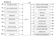
- the auxiliary machinery is constituted by the motor-driven pumps 41 a, 42a for supplying water and air, the ventilation air blower 15, the cathode air blower 44a, the deionizer antifreezing heater 14a, the water tank antifreezing heater 13b, the ignition heaters 26a, 26b1, the combustion catalyst heater 28a, the water circulation pump 32a, and the like.
- the temperature sensors 32b, 32c, 32d, 33c, the voltage sensor 32a2, the rotation sensor 32a3, the pressure sensor 32e, the power failure sensor 50a, the flow sensor 44a1, the pumps 32a, 41 a, 42a, the blowers 15, 44a, and the heaters 13b, 14a, 26a1, 26a2, 28a, the distribution board 81, and the automatic power switching device 82 are connected to the control unit 60.
- the control unit 60 includes a microcomputer having an input-output interface (I/O interface), a CPU, a RAM, and a ROM all of which are connected to one another via a bus.
- the CPU has a function to operate the fuel cell system.
- the RAM temporarily stores a variable necessary to perform program (control program) for the operation of the fuel cell system.
- the ROM stores such program.
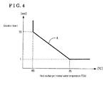
- step S102 the control unit 60 determines whether or not air bubbles are generated at the water circulation line 32. For example, the control unit 60 performs the aforementioned determination based on whether or not an internal temperature T32d of the heat exchanger 33 correlated to or based on a duration time t during which the internal temperature T32d is continued or maintained exceeds a threshold value A.
- the internal temperature T32d which is detected by the third temperature sensor 32d corresponds to the temperature of the storage water at the water circulation line 32 within the heat exchanger 33.
- the threshold value A is specified on a basis of the duration time t during which the internal temperature T32d is continued or maintained.
- the duration time t is specified to be 15 seconds. In a case where the internal temperature T32d is 75 °C, the duration time t is specified to be 1 second.
- the determination of whether or not the air bubbles are generated at the water circulation line 32 may be conducted on a basis of whether or not an outlet temperature T32c of the heat exchanger 33 at the water circulation line 32 detected by the temperature sensor 32c exceeds a predetermined value.
- the outlet temperature T32c corresponds to the temperature of the storage water flowing out of the heat exchanger 33 at the water circulation line 32.
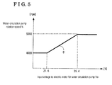
- the determination of whether or not the air bubbles are generated at the water circulation line 32 may be conducted on a basis of whether or not the rotation speed (i.e., the number of rotations) of the water circulation pump 32a relative to the input value input to the electric motor 32a1 (i.e., input voltage) that drives the water circulation pump 32a exceeds a threshold value B by the detection results of the voltage sensor 32a2 and the rotation sensor 32a3.
- the threshold value B is specified on a basis of the number of rotations N (rotation speed) of the water circulation pump 32a relative to an input voltage Va serving as the input value to the electric motor 32a1.
- the number of rotations N is 4000. In a case where the input voltage Va is 26.4 volts, the number of rotations N is 5000.
- the input voltage Va is detected by the voltage sensor 32a2.
- a predetermined voltage, i.e., 24 volts, of the input voltage Va is generally applied to the electric motor 32a1, however, the input voltage may fluctuate.
- S102 serves as an air bubble detection portion.
- control unit 60 stops the operation of the water circulation pump 32a. In association with the stop of the operation of the water circulation pump 32a, i.e., decrease or stop of rotations of the water circulation pump 32a, the circulation of the storage water at the water circulation line 32 is stopped.
- the program proceeds to S106 at the substantially same time as the program proceeds to S104 so that a timer TM starts counting. While the timer TM is counting, the circulation of the storage water at the water circulation line 32 is stopped. Thus, the air bubbles stirred by a rotation of an impeller 32f of the water circulation pump 32a are lifted up by buoyancy to be collected at an upper portion of an inside of the water circulation pump 32a. As illustrated in Fig. 6 , the air bubbles are enlarged to become a mass 32g. The air bubbles are likely to be generated at an inlet 32i of the water circulation pump 32a and a rear side of the impeller 32f in a rotation direction thereof where the water pressure decreases.
- the water circulation pump 32a also includes an outlet portion 32o as illustrated in Fig. 6 . An arrow R in Fig. 6 indicates the rotation direction of the impeller 32f.
- the control unit 60 determines whether or not the operation stop of the water circulation pump 32a continues for a predetermined time period. Specifically, the control unit 60 determines that the air bubbles are collected at the upper portion of the inside of the water circulation pump 32a to become the mass 32g serving as the large air bubbles as illustrated in Fig. 6 in a case where the value counted by the timer TM reaches or exceeds a predetermined value TM1 from the start of counting at which the air bubbles are detected.
- the predetermined value TM1 corresponds to a time period required for the air bubbles to be lifted up by buoyancy so that the air bubbles are enlarged to become the mass 32g.
- the predetermined value TM1 is specified to be 1.5 seconds.
- the control unit 60 determines Yes in S108 and the program proceeds to S110 so as to resume or return the operation of the water circulation pump 32a.
- the mass 32g collected at the upper portion of the inside of the water circulation pump 32a may be pushed out therefrom by the rotation of the water circulation pump 32a.
- the aforementioned air bubbles (the mass 32g) are moved by the operation of the water circulation pump 32a so as to eventually stay and remain at the upper portion of the water storage tank 31.
- a circulation flow rate of the storage water may be thus secured.
- deposition of a component for example, calcium
- a corrosion of the heat exchanger 33 resulting from an adhesion of a deposition substance (scale) to the heat exchanger 33 is inhibited accordingly.
- the control unit 60 determines whether or not the water pressure at the water circulation line 32 is equal to or smaller than a threshold value C based on the detection result of the pressure sensor 32e.
- the threshold value C corresponds to a water pressure at the time of cutoff of water supply or a water pressure at which a flow volume of storage water at the water circulation line 32 is ensured, for example.
- the control unit 60 determines "Yes” in S202 and the program proceeds to S204. On the other hand, in a case where it is determined that the water pressure is greater than the threshold value C, the control unit 60 determines "No” in S202 and the program proceeds to S206.
- the water circulation pump 32a is operated normally (i.e., a normal operation of the water circulation pump 32a is performed). S202 serves as a water pressure decrease detection portion.
- the output of the water circulation pump 32a increases. Specifically, the speed (the number of rotations) of the electric motor 32a1 increases to thereby increase the circulation flow rate of the storage water at the water circulation line 32 and to increase the water pressure of the storage water at the water circulation line 32. Until the water pressure reaches the threshold value C, the aforementioned operation is repeated in S202.
- the third control example is related to a control in a state where the fuel cell system performs the self-sustained operation in which the fuel cell system is configured to supply the electric power to the electric outlet 83 while supplying a necessary electric power to the auxiliary machinery of the fuel cell system for continuing the power generation in a state where the fuel cell system is disconnected from a commercial power system constituted by the power line 52 that is connected to the system power supply 51 and the electric power load 53.
- the portion of the auxiliary machinery that absorbs the surplus power in the output power of the fuel cell module 20 is a heater, specifically, the combustion catalytic heater 28a for heating the combustion catalyst to the activating temperature thereof to burn the combustible gas contained in the exhaust combustion gas
- the temperature of the exhaust combustion gas that flows into the inlet port of the heat exchanger 33 increases and the temperature of the storage water that is heated by the heat exchanger 33 excessively increases.
- the deposition of the component (for example, calcium) contained in the storage water is caused by evaporation of the storage water flowing through the heat exchanger 33.
- the corrosion of the heat exchanger 33 resulting from the adhesion of the deposition substance (scale) to the heat exchanger 33 occurs accordingly.
- the third control example aims to provide the fuel cell system that may inhibit the excessive increase of the temperature of storage water that is heated by the heat exchanger 33 in a state where the fuel cell system performs the self-sustained operation.
- the third control example includes a maximum load output limitation control portion for limiting or restricting a maximum load output of the portion of the auxiliary machinery of the fuel cell system that absorbs the surplus power in the output power of the fuel cell module 20 based on a heat capacity of the exhaust combustion gas and the temperature of the water at the inlet portion of the heat exchanger 33 into which the water flows (the heat exchanger inlet water temperature) during the self-sustained operation of the fuel cell system. Accordingly, the maximum load output of the portion of the auxiliary machinery that absorbs the surplus power in the output power of the fuel cell module 20 is restricted and limited on a basis of the heat capacity of the exhaust combustion gas and the heat exchanger inlet water temperature, i.e., heat applied to the heat exchanger 33.
- the operation of the fuel cell system by the aforementioned portion of the auxiliary machinery is restricted and limited, so that the heat resulting from the operation of the fuel cell system acting on the heat exchanger 33 is limited and restricted.
- the excessive temperature increase of the storage water that is heated by the heat exchanger 33 is inhibited accordingly.
- the deposition of the component (calcium, for example) contained in the storage water which is caused by evaporation of the storage water flowing through the heat exchanger 33, may be prevented to thereby inhibit the corrosion of the heat exchanger 33 resulting from the adhesion of the deposition substance (scale) to the heat exchanger 33.
- the heat capacity of the exhaust combustion gas is obtained by multiplication of the flow rate of cathode air sent to the fuel cell module 20 for the reaction with hydrogen, and the temperature of the exhaust combustion gas at the inlet port of the heat exchanger 33 into which the exhaust combustion gas flows (the heat exchanger inlet gas temperature). Accordingly, the heat capacity of the exhaust combustion gas may be accurately obtained on the basis of measurements of the flow rate of cathode air and the heat exchanger inlet gas temperature.
- the portion of the auxiliary machinery absorbing the surplus power in the output power of the fuel cell module 20 is specifically the heater.
- the operation of the heater serving as a heat source for thermally influencing the heat exchanger 33 is controllable.
- the heater corresponds to the combustion catalytic heater 28a, the ignition heater 26a1 or 26a2, for example.
- the heater serving as the portion of the auxiliary machinery absorbing the surplus power in the output power of the fuel cell module 20 is the combustion catalytic heater 28a provided at the inlet port of the heat exchanger 33 into which the exhaust combustion gas flows to heat the combustion catalyst to the activation temperature. Accordingly, because the heater absorbing the surplus power in the output power of the fuel cell module 20 is the combustion catalytic heater 28a provided at the inlet port of the heat exchanger 33 to heat the combustion catalyst to the activation temperature, the excessive temperature increase of the storage water at the heat exchanger 33 by the combustion catalytic heater 28a may be directly inhibited.
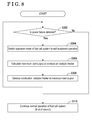
- the fuel cell system starts the power generation by the normal operation and the control unit 60 starts executing program illustrated in a flowchart in Fig. 8 .
- the control unit 60 determines whether or not the power failure of the AC voltage of the system power supply 51 occurs on a basis of the operation of the power failure sensor 50a. In a case where the power failure is detected, the control unit 60 determines "Yes" in S302 and the program proceeds to S304. On the other hand, in a case where the power failure is not detected, the control unit 60 determines "No" in S302 and the program proceeds to S310. The fuel cell system continues the normal operation.
- the control unit 60 switches the operation mode of the fuel cell system to the self-sustained operation in S304.
- the distribution board 81 and the automatic power switching device 82 are operated so that the system power supply 51 is immediately disconnected from the fuel cell system.
- the control unit 60 supplies a necessary power to the auxiliary machinery such as the pump and the fan, for example, which is necessary for continuing the power generation and supplies an electric power to the electric outlet 83.
- the household electric appliance 84 such as a television, a laptop computer, a desk lamp, or an electric fan, for example, is connected to the electric outlet 83 to be usable so that the self-sustained operation at the time of power failure is achieved.
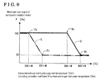
- the program proceeds to S306 at the substantially same time as the program proceeds to S304 to calculate a maximum load output P of the combustion catalytic heater 28a. Specifically, the calculation of the maximum load output P of the combustion catalytic heater 28a is conducted by using a control map illustrated in Fig.
- the maximum load output P of the combustion catalytic heater 28a is specified within a range from 100% to 30% as indicated by a solid line D in Fig.
- the corrected heat exchanger inlet gas temperature T33cm is obtained by multiplying the heat exchanger inlet gas temperature T33c by a correction coefficient M which is based on a difference between a reference temperature of the heat exchanger inlet water temperature T32b and an operation temperature of the heat exchanger inlet water temperature T32b (i.e., temperature in a state where the fuel cell system is operated).
- the corrected heat exchanger inlet gas temperature T33cm is obtained by the correction of the heat exchanger inlet gas temperature T33c by the correction coefficient M which converts the difference between the reference temperature and the operation temperature of the heat exchanger inlet water temperature T32b into the heat exchanger inlet gas temperature T33c.
- the maximum load output P of the combustion catalytic heater 28a decreases from 100% at which a limitation control is started as indicated by a point Dy on the solid line D to 30% serving as an upper limit as indicated by a point Dz, and changes proportionally between the point Dy and the point Dz in association with increase of the heat exchanger inlet gas temperature T33c.
- the corrected heat exchanger inlet gas temperature T33cm at the point Dy is 360 x M °C, for example.
- the corrected heat exchanger inlet gas temperature T33cm at the point Dz is 400 x M °C, for example.
- the maximum load output P of the combustion catalytic heater 28a decreases from 100% at which the limitation control is started as indicated by a point Ey on a chain double-dashed line E to 30% serving as the upper limit as indicated by a point Ez, and changes proportionally between the point Ey and the point Ez in association with increase of the heat exchanger inlet gas temperature T33c.
- the corrected heat exchanger inlet gas temperature T33cm at the point Ey is 300 x M °C, for example.
- the corrected heat exchanger inlet gas temperature T33cm at the point Ez is 320 x M °C, for example.
- the corrected heat exchanger inlet gas temperature T33cm based on which the maximum load output P of the combustion catalytic heater 28a is determined as the limitation control start or the upper limit is specified to decrease in a case where the discharge amount Q of the cathode air blower 44a increases to 64.5 NLM as compared to a case where the discharge amount Q of the cathode air blower 44a is 19.15 NLM. It may be clear that the limitation control start and the upper limit of the maximum load output P of the combustion catalytic heater 28a is specified on the basis of the discharge amount Q of the cathode air blower 44a and the corrected exhaust combustion gas inlet temperatureT33cm.
- the program proceeds to S308 in which the combustion catalytic heater 28a is controlled to operate with the value (i.e., 100% to 30%) of the maximum load output P calculated in S306, i.e., the output of the combustion catalytic heater 28a is limited and restricted as calculated in S306. Accordingly, an excessive increase of an inside temperature of the heat exchanger 33 (excessive heating of the heat exchanger 33) resulting from heating of the exhaust combustion gas is inhibited.
- the operation in S308 is repeated until the power failure is not detected in S302, i.e., until the power supply is recovered.
- S306 and S308 collectively serve as the maximum load output limitation control portion.
- the fuel cell system of the embodiment includes the fuel cell module 20 performing the power generation by electrochemical reaction and discharging the exhaust combustion gas that is generated by the power generation, the water storage tank 31 storing water that serves as the storage water, the water circulation line 32 (storage water circulation line) at which the storage water circulates, the water circulation pump 32a (storage water circulation pump) provided at the water circulation line 32 and driven by the electric motor 32a1, the heat exchanger 33 performing the heat exchange between the exhaust combustion gas and the storage water, the air bubble detection portion S102 detecting a generation of air bubbles at the water circulation line 32 and the control unit 60 controlling the water circulation pump 32a to stop operating for a predetermined time period in response to an air bubble detection signal generated by the air bubble detection portion S102 and to resume the operation of the water circulation pump 32a.
- the operation of the water circulation pump 32a is controlled to stop for the predetermined time period so that the air bubbles which are stirred are raised by buoyancy to be collected at the upper portion of the inside of the water circulation pump 32a, which results in a mass of air bubbles (enlarged air bubbles).
- the mass of air bubbles may be pushed out by the return or recovery of the operation of the water circulation pump 32a.
- the air bubbles move to the upper portion of the water storage tank 31 to stay thereat eventually so that the circulation flow rate of the storage water may be ensured.
- the deposition of the component (calcium, for example) contained in the storage water which is caused by evaporation of the storage water flowing through the heat exchanger 33, is inhibited.
- the corrosion of the heat exchanger 33 resulting from the adhesion of the deposition substance (scale) to the heat exchanger 33 is inhibited accordingly.
- the air bubble detection portion S102 generates the air bubble detection signal in a case where one of the internal temperature T32d and the outlet temperature T32c of the heat exchanger 33 exceeds a threshold value.
- the air bubbles When the air bubbles are generated, the flow rate of the storage water decreases due to the generation of air bubbles and a cooling performance of the storage water is weaken.
- the generation of air bubbles is detectable on the basis of measurement of increase of the internal temperature T32d or the outlet temperature T32c of the heat exchanger 33.
- the air bubble detection portion S102 generates the air bubble detection signal in a case where the number of rotations (the rotation speed) N of the water circulation pump 32a relative to the input value Va to the electric motor 32a1 exceeds the threshold value B.
- the number of rotations N of the water circulation pump 32a increases because the air bubbles are lighter than the storage water and thus a load relative to the water circulation pump 32a decreases. Consequently, the generation of air bubbles is detectable on the basis of the measurement of the number of rotations (rotation speed) N of the water circulation pump 32a.
- the fuel cell system includes the water pressure decrease detection portion S202 detecting that the water pressure at the water circulation line 32 is lower than the threshold value C.
- the control unit 60 controls the operation of the water circulation pump 32a so that the flow rate of the storage water flowing through the water circulation line 32 increases in response to a water pressure decrease detection signal generated by the water pressure decrease detection portion S202.
- the water circulation pump 32a is operated to increase the flow rate of the storage water flowing through the water circulation line 32 so as to ensure the flow rate of the storage water.
- the water pressure decrease detection portion S202 includes the pressure sensor 32e provided at the upstream side than the heat exchanger 33 at the water circulation line 32.
- the decrease of water pressure at the water circulation line 32 is directly detectable by the pressure sensor 32e.
- the fuel cell system includes the fuel cell module 20 performing the power generation by electrochemical reaction and discharging the exhaust combustion gas that is generated by the power generation, the water storage tank 31 storing water that serves as the storage water, the water circulation line 32 at which the storage water circulates, the heat exchanger 33 performing the heat exchange between the exhaust combustion gas and the storage water, and the maximum load output limitation control portion S306, S308 restricting the maximum load output P of the portion of the auxiliary machinery which is configured to absorb the surplus electric power in the output electric power of the fuel cell module 20 based on the heat capacity of the exhaust combustion gas and the temperature (heat exchanger inlet water temperature) T32b of the storage water at the inlet portion of the heat exchanger 33 into which the storage water flows in a state where the self-sustained operation at the power failure is performed, in the self-sustained operation in which an electric power is configured to be supplied to the external electric outlet for the self-sustained operation (electric outlet) 83 while a necessary electric power is supplied to the auxiliary machinery for continuing the power generation in
- the maximum load output P of the portion of the auxiliary machinery that absorbs the surplus power in the output power of the fuel cell module 20 is limited and restricted on the basis of the heat capacity of the exhaust combustion gas and the heat exchanger inlet water temperature T32b, i.e., on the basis of the heat acting on the heat exchanger 33.
- the operation of the fuel cell system by the aforementioned auxiliary machinery is restricted.
- the heat acting on the heat exchanger 33 because of the operation of the fuel cell system is restricted accordingly.
- the excessive temperature increase of the storage water heated by the heat exchanger 33 is inhibited.
- the deposition of the component (calcium, for example) contained in the storage water, caused by evaporation of the storage water flowing through the heat exchanger 33, is inhibited so that the corrosion of the heat exchanger 33 resulting from the adhesion of the deposition substance (scale) to the heat exchanger 33 is inhibited.
- the heat capacity of the exhaust combustion gas is obtained by multiplication of the flow rate of cathode air sent to the fuel cell module 20 for the reaction with hydrogen and the heat exchanger inlet gas temperature T33c. Accordingly, the heat capacity of the exhaust combustion gas may be accurately obtained on the basis of measurements of the flow rate of cathode air and the temperature of the exhaust combustion gas at the inlet port of the heat exchanger 33.
- the portion of the auxiliary machinery that absorbs the surplus power in the output power of the fuel cell module 20 is the heaters 28a, 26a1 and 26a2.
- the operations of the aforementioned heaters each of which serves as the heat source for thermally influencing the heat exchanger 33 are controllable.
- the heater that absorbs the surplus power in the output power of the fuel cell module 20 is the combustion catalytic heater 28a heating the combustion catalyst to the activating temperature thereof, the combustion catalytic heater 28a being provided at the inlet port of the heat exchanger 33 into which the exhaust combustion gas flows.
- the excessive temperature increase of the storage water at the heat exchanger 33 by the combustion catalytic heater 28a is inhibited.
- a fuel cell system includes a fuel cell module (20) performing a power generation and discharging an exhaust combustion gas generated by the power generation, a water storage tank (31) storing water that serves as a storage water, a storage water circulation line (32) at which the storage water circulates, a storage water circulation pump (32a) provided at the storage water circulation line and driven by an electric motor, a heat exchanger performing a heat exchange (33) between the exhaust combustion gas and the storage water, an air bubble detection portion (S102) detecting a generation of air bubbles at the storage water circulation line and a control unit (60) controlling the storage water circulation pump to stop operating for a predetermined time period in response to an air bubble detection signal generated by the air bubble detection portion and to resume the operation of the storage water circulation pump.
Landscapes
- Engineering & Computer Science (AREA)
- Chemical & Material Sciences (AREA)
- Combustion & Propulsion (AREA)
- Chemical Kinetics & Catalysis (AREA)
- Sustainable Energy (AREA)
- Sustainable Development (AREA)
- Life Sciences & Earth Sciences (AREA)
- Electrochemistry (AREA)
- General Chemical & Material Sciences (AREA)
- Manufacturing & Machinery (AREA)
- Physics & Mathematics (AREA)
- Thermal Sciences (AREA)
- Mechanical Engineering (AREA)
- General Engineering & Computer Science (AREA)
- Fuel Cell (AREA)
Abstract
Description
- This disclosure generally relates to a fuel cell system.
- A known fuel cell system performs a heat exchange between exhaust heat of a fuel cell module and storage water (hot or warmed water) so that the exhaust heat is recovered and stored in the storage water. The fuel cell system therefore includes the fuel cell module for performing a power generation by electrochemical reaction and emitting exhaust combustion gas that is generated by the power generation, a water storage tank storing water (hot or warmed water) that serves as the storage water, a water circulation line at which the storage water is circulated, a water circulation pump provided at the water circulation line, and a heat exchanger that performs the heat exchange between the exhaust combustion gas from the fuel cell module and the storage water. Because the storage water is heated at the heat exchanger, dissolved air such as air dissolved in the storage water or water vapor, for example, turns to air bubbles which stay or remain at the storage water circulation line. In consequence, a circulation flow rate of the storage water may be difficult to be secured.
- In order to solve the aforementioned drawback, according to a fuel cell system disclosed in
JP2006-24431 A Reference 1, in a case where it is determined that the air bubbles exist within the heat exchanger or the storage water circulation line, for example, and that the aforementioned air bubbles block a flow of the storage water, the water circulation pump is controlled to produce a maximum power output, thereby pushing out the air bubbles within the heat exchanger or the storage water circulation line. - Nevertheless, according to the fuel cell system disclosed in
Reference 1, in a case where a pressure of the storage water (water pressure) at the storage water circulation line decreases, i.e., in a case where the water pressure decreases by cutoff of water supply to the water storage tank, for example, the dissolved air in the storage water is likely to become air bubbles based on Henry's law and Dalton's law. In addition, even when the number of rotations (i.e., rotation speed) of the storage water circulation pump increases by the maximum output power thereof so that the air bubbles are pushed out, for example, the water pressures at an inlet of the storage water circulation pump for suctioning the storage water and a periphery of an impeller of the storage water circulation pump decrease, which may cause the dissolved air in the storage water to easily become the air bubbles. As a result, the increased air bubbles are stirred by the operation of the storage water circulation pump, which may lead to an idle running of the storage water circulation pump and a difficulty in pushing out the air bubbles. - A need thus exists for a fuel cell system which may push out air bubbles from a storage water circulation line even in a case where a pressure of storage water at the storage water circulation line decreases.
- According to an aspect of this disclosure, a fuel cell system includes a fuel cell module performing a power generation by an electrochemical reaction and discharging an exhaust combustion gas that is generated by the power generation, a water storage tank storing water that serves as a storage water, a storage water circulation line at which the storage water circulates, a storage water circulation pump provided at the storage water circulation line and driven by an electric motor, a heat exchanger performing a heat exchange between the exhaust combustion gas and the storage water, an air bubble detection portion detecting a generation of air bubbles at the storage water circulation line and a control unit controlling the storage water circulation pump to stop operating for a predetermined time period in response to an air bubble detection signal generated by the air bubble detection portion and to resume the operation of the storage water circulation pump.
- Accordingly, in a case where it is detected that the air bubbles are generated at the storage water circulation line, the operation of the storage water circulation pump is controlled to stop for the predetermined time period so that the air bubbles which are stirred are raised by buoyancy to be collected at an upper portion of an inside of the storage water circulation pump, which results in a mass of air bubbles (enlarged air bubbles). The mass of air bubbles may be pushed out by a return or recovery of the operation of the storage water circulation pump. The air bubbles move to the upper portion of the water storage tank to stay thereat eventually so that a circulation flow rate of the storage water may be ensured. As a result, deposition of a component (calcium, for example) contained in the storage water, which is caused by evaporation of the storage water flowing through the heat exchanger, is inhibited. A corrosion of the heat exchanger resulting from an adhesion of a deposition substance (scale) to the heat exchanger is inhibited accordingly.
- The air bubble detection portion generates the air bubble detection signal in a case where one of an internal temperature and an outlet temperature of the heat exchanger exceeds a threshold value.
- When the air bubbles are generated, the flow rate of the storage water decreases due to the generation of air bubbles and a cooling performance of the storage water is weaken. Thus, the generation of air bubbles is detectable on the basis of measurement of increase of the internal temperature or the outlet temperature of the heat exchanger.
- The air bubble detection portion generates the air bubble detection signal in a case where a rotation speed of the storage water circulation pump relative to an input value to the electric motor exceeds a threshold value.
- When the air bubbles are generated, the rotation speed of the storage water circulation pump increases because the air bubbles are lighter than the storage water and thus a load relative to the storage water circulation pump decreases. Consequently, the generation of air bubbles is detectable on the basis of measurement of the rotation speed of the storage water circulation pump.
- The fuel cell system further includes a water pressure decrease detection portion detecting that a water pressure at the storage water circulation line is lower than a threshold value. The control unit controls the operation of the storage water circulation pump so that a flow rate of the storage water flowing through the storage water circulation line increases in response to a water pressure decrease detection signal generated by the water pressure decrease detection portion.
- Accordingly, in a case where the water pressure at the storage water circulation line becomes lower than the threshold value, the storage water circulation pump is operated to increase the flow rate of the storage water flowing through the storage water circulation line so as to ensure the flow rate of the storage water.
- The water pressure decrease detection portion includes a pressure sensor provided at an upstream side than the heat exchanger at the storage water circulation line.
- Accordingly, the decrease of water pressure at the storage water circulation line is directly detectable by the pressure sensor.
- The foregoing and additional features and characteristics of this disclosure will become more apparent from the following detailed description considered with the reference to the accompanying drawings, wherein:
-
Fig. 1 is a schematic view illustrating a fuel cell system according to an embodiment disclosed here; -
Fig. 2 is a block diagram of the fuel cell system illustrated inFig. 1 ; -
Fig. 3 is a flowchart of a control program (first control example) performed by a control unit illustrated inFig. 2 ; -
Fig. 4 is a graph illustrating a threshold value for a temperature of storage water at an inside of a heat exchanger used for a detection of air bubbles; -
Fig. 5 is a graph illustrating a threshold value for a rotation speed of a water circulation pump used for the detection of air bubbles; -
Fig. 6 is an explanatory view illustrating the water circulation pump and a mass of air bubbles; -
Fig. 7 is a flowchart of a control program (second control example) performed by the control unit illustrated inFig. 2 ; -
Fig. 8 is a flowchart of a control program (third control example) performed by the control unit illustrated inFig. 2 ; and -
Fig. 9 is a graph illustrating an example of a maximum load output of a combustion catalytic heater during a self-sustained operation of the fuel cell system. - An embodiment will be explained with reference to the attached drawings. As illustrated in
Fig. 1 , a fuel cell system of the embodiment includes acase 11 substantially in a box form, afuel cell module 20, an exhaustheat recovery system 30, aninverter device 50, and acontrol unit 60. - The
case 11 includes apartition member 12 dividing an inside of thecase 11 into a first chamber R1 serving as a first void and a second chamber R2 serving as a second void. Thepartition member 12 is a member dividing or separating the inside of thecase 11 in a vertical direction (in an up-and-down direction). The first chamber R1 and the second chamber R2 are in communication with each other. - The
fuel cell module 20 is accommodated within the first chamber R1 while having a distance (or a void) from an inner wall surface of the first chamber R1. Thefuel cell module 20 at least includes acasing 21 and afuel cell 24. According to the present embodiment, thefuel cell module 20 includes thecasing 21, an evaporatingportion 22, a reformingportion 23, and thefuel cell 24. - The
casing 21 in a box form is made of an insulative material. Thecasing 21 is disposed at thepartition member 12 via a support structure within the first chamber R1 while having the distance from the inner wall surface of the first chamber R1. The evaporatingportion 22, the reformingportion 23, thefuel cell 24, and a combustion void R3 serving as a first combustingportion 26 are arranged within thecasing 21 in a state where the evaporatingportion 22 and the reformingportion 23 are positioned at an upper side of thefuel cell 24. - The evaporating
portion 22, which is heated by combustion gas, evaporates water (i.e., water for reforming) supplied to the evaporatingportion 22 so as to generate water vapor and preheats a source material (fuel) supplied to the evaporatingportion 22. The evaporatingportion 22 mixes the water vapor generated in the aforementioned manner and the source material that is preheated so as to supply the mixture to the reformingportion 23. The source material corresponds to gaseous fuel such as natural gas and LPG, for example, and liquid fuel such as kerosene, gasoline, and methanol, for example. According to the present embodiment, the natural gas is used as the source material. - A first end of a
water supply pipe 41 is connected to the evaporatingportion 22. A second end (a lower end) of thewater supply pipe 41 is connected to a water tank 13 (a water reservoir) so that the second end is positioned within thewater tank 13. Awater pump 41 a is provided at thewater supply pipe 41. The water pump 41 a supplies water to the evaporatingportion 22 and controls or adjusts a volume of water (i.e., a flow rate of water per unit time) supplied to the evaporatingportion 22. Thewater pump 41 a supplies condensed water stored at thewater tank 13 to the evaporatingportion 22 as water for reforming. - The source material is supplied to the evaporating
portion 22 via afuel supply pipe 42 from a supply source of the source material (which will be hereinafter simply referred to as a supply source) Gs. The supply source Gs corresponds to a city gas supply line or an LP gas cylinder, for example. Afuel pump 42a is provided at thefuel supply pipe 42 in a state to be housed in thecase 11. Thefuel pump 42a is a supply device that supplies fuel (source material) to thefuel cell 24. In response to a control command value from thecontrol unit 60, thefuel pump 42a adjusts or controls a supply amount of fuel (i.e., a flow rate of fuel per unit time) from the supply source Gs. Thefuel pump 42a suctions the source material and sends the source material in a pressing manner to the evaporatingportion 22. - The reforming
portion 23 is heated by the combustion gas so as to receive heat necessary for a water vapor reforming reaction. As a result, the reformingportion 23 generates reformed gas from mixed gas (source material and water vapor) supplied from the evaporatingportion 22. Specifically, the inside of the reformingportion 23 is filled with a catalyst, for example, a ruthenium catalyst (Ru catalyst) and a nickel catalyst (Ni catalyst). The mixed gas supplied from the evaporatingportion 22 reacts by means of the catalyst so as to be reformed, thereby generating hydrogen gas and carbon monoxide gas (water vapor reforming reaction). At the same time, carbon monoxide generated during the water vapor reforming reaction and water vapor react so as to be converted to hydrogen gas and carbon dioxide, i.e., a carbon monoxide shift reaction occurs. The thus generated gas (reformed gas) is supplied to a fuel electrode of thefuel cell 24. The reformed gas includes hydrogen, carbon monoxide, carbon dioxide, water vapor, natural gas (methane gas) that is not reformed, and water (water vapor) not used for reforming. Accordingly, the reformingportion 23 generates the reformed gas serving as fuel from the source material and water to supply the reformed gas to thefuel cell 24. The water vapor reforming reaction is an endothermic reaction while the carbon monoxide shift reaction is an exothermic reaction. - The
fuel cell 24 includes a lamination ofplural cells 24a each including a fuel electrode, an air electrode (an oxidant electrode), and an electrolyte disposed between the fuel electrode and the air electrode. Thefuel cell 24 according to the present embodiment is a solid oxide fuel cell (SOFC) where zirconium oxide serving as a solid oxide is used as the electrolyte. The fuel electrode of thefuel cell 24 is supplied with hydrogen, carbon monoxide, and methane gas, for example, as fuel. An operating temperature of thefuel cell 24 is substantially in a range from 400 °C to 1,000 °C. Not only hydrogen is used as the fuel but also natural gas or coal gas may be directly used as the fuel. When the natural gas or the coal gas is directly used as the fuel, the reformingportion 23 may be omitted. Afuel flow passage 24b through which the reformed gas serving as the fuel flows is formed at each of thecells 24a so as to face the fuel electrode thereof. Anair flow passage 24c through which air (cathode air) serving as oxidant gas flows is formed at each of thecells 24a so as to face the air electrode thereof. - The
fuel cell 24 is placed on amanifold 25. The reformed gas is supplied from the reformingportion 23 to the manifold 25 via a reformedgas supply pipe 43. A lower end (a first end) of thefuel flow passage 24b is connected to a fuel lead-out port formed at the manifold 25. The reformed gas led out from the fuel lead-out port of the manifold 25 is introduced from the lower end of thefuel flow passage 24b and is discharged from an upper end of thefuel flow passage 24b. The cathode air sent from acathode air blower 44a flows through a cathodeair supply pipe 44 so as to be supplied from a lower end of theair flow passage 24c and be discharged from an upper end of theair flow passage 24c. - The
cathode air blower 44a is arranged within the second chamber R2. Thecathode air blower 44a suctions air within the second chamber R2 and discharges the air to the air electrode of thefuel cell 24. A discharge volume of air by thecathode air blower 44a is regulated and controlled (for example, controlled on a basis of a load electric power (power consumption) of the fuel cell 24). A flow sensor 44a1 provided at a downstream side of thecathode air blower 44a at the cathodeair supply pipe 44 detects a flow rate of cathode air discharged from thecathode air blower 44a. - In the
fuel cell 24, the fuel supplied to the fuel electrode and the oxidant gas supplied to the air electrode achieve a power generation. Reactions indicated by a chemical formula (1) and a chemical formula (2) as below occur at the fuel electrode while a reaction indicated by a chemical formula (3) as below occurs at the air electrode. That is, oxide ion (O2-) generated at the air electrode penetrates through the electrolyte so as to react with hydrogen at the fuel electrode, thereby generating an electric energy. As a result, the reformed gas and the oxidant gas (air) that have not been used in the power generation are discharged from thefuel flow passage 24b and theair flow passage 24c respectively.
(1) H2 + O2- → H2O + 2e-
(2) CO + O2- → CO2 + 2e-
(3) 1/2O2 + 2e- → O2-
- The reformed gas (anode-off gas) that has not been used in the power generation is discharged from the
fuel flow passage 24b and is burnt at the combustion void R3 formed between thefuel cell 24 and the evaporating portion 22 (the reforming portion 23) by means of the oxidant gas (cathode-off gas) that has not been used in the power generation. The resulting combustion gas (flames 27) heats the evaporatingportion 22 and the reformingportion 23, and further brings the inside of thefuel cell module 20 to be heated at an operating temperature. Afterwards, the combustion gas is discharged to the outside of thefuel cell module 20 from an exhaust opening 21 a. Accordingly, the aforementioned combustion void R3 constitutes the first combustingportion 26 heating the reformingportion 23 by burning the anode-off gas and the cathode-off gas from thefuel cell 24. Thefirst combusting portion 26 receives combustible gas including unused fuel not used for generating an electric power from thefuel cell 24 to burn the combustible gas by the oxidant gas and sends out exhaust combustion gas. The anode-off gas is burnt to generate theflames 27 at the first combusting portion 26 (the combustion void R3). First and second ignition heaters 26a1 and 26a2 are provided at the first combustingportion 26 so as to ignite the anode-off gas. - The exhaust
heat recovery system 30 performs a heat exchange between exhaust heat of thefuel cell 24 and storage water so that the exhaust heat is recovered and stored in the storage water. The exhaustheat recovery system 30 includes awater storage tank 31 storing water (hot or warmed water) serving as the storage water, a water circulation line 32 (a storage water circulation line) where the water (storage water) is circulated, and aheat exchanger 33 where the heat exchange is performed between the exhaust combustion gas from thefuel cell module 20 and the water (storage water). - The
water storage tank 31 includes a single columnar container in which the water (hot or warmed water) is stored in such a manner that a temperature is the highest at an upper portion of the water in the container, is gradually decreasing towards a lower portion of the water, and is the lowest at the lower portion of the water in the container. A water supply source Ws, i.e., a water pipe, for example, is connected to a lower portion of the columnar container of thewater storage tank 31 so that water at a relatively low temperature is supplied from the water supply source Ws, for example, tap water is supplied, to thewater storage tank 31. Apressure sensor 32e is provided at an entrance of thewater storage tank 31 where the water is supplied from the water supply source Ws so as to detect a pressure of the water supplied to thewater storage tank 31 from the water supply source Ws and to send a detection result to thecontrol unit 60. Alternatively, thepressure sensor 32e may be disposed at an upstream side of awater circulation pump 32a (a storage water circulation pump) that is provided at thewater circulation line 32 to send the detection result to thecontrol unit 60. Then, based on the detection result from thepressure sensor 32e, the water pressure at thewater circulation line 32 and a cutoff of water supply from the water supply source Ws is detectable. In addition, the water at a high temperature, i.e., hot or warmed water, stored at thewater storage tank 31 is led out from the upper portion of the columnar container of thewater storage tank 31. - A first end of the
water circulation line 32 is connected to the lower portion of thewater storage tank 31 while a second end of thewater circulation line 32 is connected to the upper portion of thewater storage tank 31. Thewater circulation pump 32a, afirst temperature sensor 32b, theheat exchanger 33, athird temperature sensor 32d, and asecond temperature sensor 32c are provided in the mentioned order at thewater circulation line 32 from the first end towards the second end thereof. Thewater circulation pump 32a suctions the water (storage water) at the lower portion of thewater storage tank 31 so that the water flows in an arrow direction inFig. 1 through thewater circulation line 32 to be supplied and discharged to the upper portion of thewater storage tank 31. A flow rate (a sending amount) of the water flowing through thewater circulation line 32 is controlled by thewater circulation pump 32a. The sending amount of the water by thewater circulation pump 32a is controlled so that a detection temperature by thesecond temperature sensor 32c (i.e., a temperature of the water at an inlet side of the water storage tank 31) turns to be a predetermined temperature or falls within a predetermined temperature range. - The
water circulation pump 32a is driven by an electric motor 32a1. Thewater circulation pump 32a rotates at a predetermined speed (i.e., predetermined rotation numbers) in response to an input value input to the electric motor 32a1, i.e., a voltage value of a power supply voltage. A voltage sensor 32a2 detects the input value of the electric motor 32a1, i.e., the voltage value of the power supply voltage, and sends a detection result to thecontrol unit 60. A rotation sensor 32a3 detects a rotation speed (rotation numbers) of thewater circulation pump 32a and sends a detection result to thecontrol unit 60. - The
first temperature sensor 32b is provided at a portion of thewater circulation line 32 where the storage water flows towards theheat exchanger 33 between theheat exchanger 33 and thewater storage tank 31. Thefirst temperature sensor 32b detects the temperature of the water at an inlet portion of theheat exchanger 33 into which the water flows (i.e., a heat exchanger inlet water temperature) corresponding to the temperature of the water that flows out of (exits from) the water storage tank 31 (i.e., a storage tank outlet water temperature). Thefirst temperature sensor 32b transmits a detection result to thecontrol unit 60. - The
second temperature sensor 32c is provided at a portion of thewater circulation line 32 where the storage water flows out from theheat exchanger 33. Thesecond temperature sensor 32c detects the temperature of the water at an outlet portion of theheat exchanger 33 out of which the water flows (i.e., a heat exchanger outlet water temperature) corresponding to the temperature of the water that flows into the water storage tank 31 (i.e., a storage tank inlet water temperature). Thesecond temperature sensor 32c transmits a detection result to thecontrol unit 60. - The
third temperature sensor 32d is provided at a portion of thewater circulation line 32 within theheat exchanger 33. Thethird temperature sensor 32d detects the temperature of the water at an inside of the heat exchanger 33 (i.e., a heat exchanger internal water temperature). Thethird temperature sensor 32d transmits a detection result to thecontrol unit 60. - The
heat exchanger 33 is supplied with the exhaust combustion gas emitted from thefuel cell module 20 and with the storage water from thewater storage tank 31 so as to perform the heat exchange between the exhaust combustion gas and the storage water. Theheat exchanger 33 is arranged within thecase 11. According to the present embodiment, theheat exchanger 33 is provided at a lower side of thefuel cell module 20. At least a lower portion of theheat exchanger 33 penetrates through thepartition member 12 and projects to the second chamber R2. - The
heat exchanger 33 includes acasing 33a. An upper portion of thecasing 33a is in communication with the exhaust opening 21 a provided at a lower portion of thecasing 21 of thefuel cell module 20 so that the exhaust combustion gas is discharged through the exhaust opening 21 a. Anexhaust pipe 46, which is connected to anexhaust port 11 a, is connected to a lower portion of thecasing 33a. A condensedwater supply pipe 47 connected to adeionizer 14 is connected to a bottom portion of thecasing 33a. Aheat exchanging portion 33b serving as a condensation portion connected to thewater circulation line 32 is provided within thecasing 33a. - According to the
heat exchanger 33 including the aforementioned configuration, the exhaust combustion gas from thefuel cell module 20 flows into thecasing 33a through the exhaust opening 21 a. In a case where the exhaust combustion gas flows through theheat exchanging portion 33b where the storage water flows, the heat exchange is performed between the exhaust combustion gas and the storage water, thereby causing the exhaust combustion gas to be condensed and cooled. The exhaust combustion gas after condensation flows through theexhaust pipe 46 to be discharged to the outside of thecase 11 via theexhaust port 11 a. Condensed water resulting from the aforementioned heat exchange flows through the condensedwater supply pipe 47 so as to be supplied to the deionizer 14 (i.e., the condensed water drops by its own weight). On the other hand, the storage water flowing to theheat exchanging portion 33b is heated so as to flow out towards the upper portion of thewater storage tank 31. - Accordingly, the
heat exchanger 33 serves as a condenser that generates the condensed water by condensation of water vapor in gas that flows through the fuel cell system and that includes water via the heat exchange between the gas and a heat medium in liquid state. In the embodiment, the gas including water and flowing through the fuel cell system is the exhaust combustion gas and the heat medium in liquid state is the storage water. - A
second combusting portion 28 is provided at an inlet port of theheat exchanger 33 into which the exhaust combustion gas flows, i.e., at the exhaust opening 21 a of thecasing 21. Thesecond combusting portion 28 receives and brings in offgas of the first combustingportion 26, i.e., unused combustible gas discharged from the first combusting portion 26 (for example, hydrogen, methane gas, or carbon monoxide) so as to burn and send out the aforementioned offgas. Thesecond combusting portion 28 is constituted by a combustion catalyst serving as a catalyst for burning the combustible gas. The combustion catalyst is obtained, for example, by noble metal such as platinum or palladium deposited on a ceramic carrier. A pellet catalyst, a ceramic honeycomb catalyst, or a metal honeycomb catalyst may be used as the combustion catalyst. In addition, noble metal may be deposited on a foam metal carrier, for example. - A combustion
catalytic heater 28a is provided at thesecond combusting portion 28 for heating the combustion catalyst to an activating temperature thereof so as to burn the combustible gas. The combustioncatalytic heater 28a is operated by a command of thecontrol unit 60. - A
fourth temperature sensor 33c is provided at a portion (inlet port) of theheat exchanger 33 where the exhaust combustion gas flows in, i.e., at the downstream side of thecombustion catalyst heater 28a. Thefourth temperature sensor 33c detects the temperature of the exhaust combustion gas that flows into (enters) the heat exchanger 33 (i.e., a heat exchanger inlet gas temperature) and sends a detection result to thecontrol unit 60. - The fuel cell system of the present embodiment also includes the
water tank 13 and thedeionizer 14. Thewater tank 13 and thedeionizer 14 are arranged within the second chamber R2. Thewater tank 13 stores pure water (deionized water) supplied from thedeionizer 14. Thewater tank 13 is a water reservoir for storing the condensed water supplied from theheat exchanger 33. In the embodiment, a condensation water line which includes thewater tank 13 serves as a water conduit through which the condensation water flowing out from theheat exchanger 33 flows. The condensation water line Lg is constituted by the condensedwater supply pipe 47, thedeionizer 14, apipe 48 and thewater tank 13. Alternatively, the condensation water line Lg may be constituted without thedeionizer 14. - A water
tank antifreezing heater 13b serving as a heating device is provided at thewater tank 13 for heating the condensation water within the water tank 13 (i.e., for heating the water tank 13). The heating device is configured to heat the condensation water, i.e., condensation water system. The watertank antifreezing heater 13b corresponds to, for example, an electric heater or a combustion device (for example, a burner) and is configured to be controlled by thecontrol unit 60. The watertank antifreezing heater 13b heats thewater tank 13 so that thewater tank 13 is inhibited from being frozen. - The
deionizer 14 brings the condensation water sent from theheat exchanger 33 to be formed into the pure water (deionized water) by means of ion-exchange resin. Thedeionizer 14 is in communication with thewater tank 13 via thepipe 48. The pure water in thedeionizer 14 is supplied to thewater tank 13 by flowing through thepipe 48. That is, thedeionizer 14 makes the condensation water supplied from thewater tank 13 to be formed into the pure water which is then supplied to thewater tank 13. - A
deionizer antifreezing heater 14a serving as a heating device is provided at thedeionizer 14 for heating the condensation water within the deionizer 14 (i.e., for heating the deionizer 14). Thedeionizer antifreezing heater 14a is configured in the similar way to the watertank antifreezing heater 13b. Thedeionizer antifreezing heater 14a heats thedeionizer 14 so that thedeionizer 14 is inhibited from being frozen. - The fuel cell system includes a drainage system 70. The drainage system 70 includes a water-receiving member 71 and a drainage pipe 72. The water-receiving member 71 at least receives water leaking from the
water tank 13 that is provided within thecase 11. Respective lower ends of anoverflow line 13c and adrain pipe 46a are disposed immediately above the water-receiving member 71. Thus, the water-receiving member 71 may securely receive the water leaking from thewater tank 13 via theoverflow line 13c. Outside water, for example, rainwater that enters through theexhaust port 11 a may be securely received via theexhaust pipe 46 and thedrain pipe 46a. The drainage pipe 72 is configured to discharge the water received by the water-receiving member 71 to the outside of thecase 11. - An upper end of the
drain pipe 46a is connected to theexhaust pipe 46. The lower end of thedrain pipe 46a is elongated downward to an upper position of the water-receiving member 71. Thedrain pipe 46a is provided to restrain the outside water that enters through theexhaust port 11 a from flowing into thedeionizer 14 via theheat exchanger 33. - The fuel cell system includes an air inlet port 11 b formed at the
case 11 forming the second chamber R2, anair outlet port 11 c formed at thecase 11 forming the first chamber R1, and aventilation air blower 15 provided at the air inlet port 11 b. Theventilation air blower 15 is a ventilator for ventilating thecase 11. In a case where theventilation air blower 15 is operated, outside air is suctioned to theventilation air blower 15 via the air inlet port 11 b and is sent to the second chamber R2. Further, gas (mainly air) within the second chamber R2 flows to the first chamber R1 by passing through thepartition member 12. Gas within the first chamber R1 is discharged to the outside of thecase 11 via theair outlet port 11c. - The fuel cell system also includes the
inverter device 50. Theinverter device 50 includes a first function for receiving a direct-current (DC) voltage output from thefuel cell 24 and converting the DC voltage into a predetermined alternating-current (AC) voltage so as to output the AC voltage to apower line 52 connected to an alternating system power supply 51 (hereinafter simply referred to as a system power supply 51) and an external electric power load 53 (hereinafter simply referred to as an electric power load 53). Theinverter device 50 also includes a second function for receiving an AC voltage from thesystem power supply 51 via thepower line 52 and converting the AC voltage into a predetermined DC voltage so as to output the DC voltage to an auxiliary machinery and/or thecontrol unit 60. Theinverter device 50 further includes apower failure sensor 50a that detects a power failure of the AC voltage of thesystem power supply 51 and transmits a detection result to thecontrol unit 60. - The system power supply (or a commercial power supply) 51 supplies the electric power to the
electric power load 53 via thepower line 52 connected to thesystem power supply 51. Thefuel cell 24 is connected to thepower line 52 via theinverter device 50. Theelectric power load 53 is a load driven by an AC power source, i.e., a hair drier, a refrigerator, and a television, for example. - Further, as illustrated in
Fig. 1 , the fuel cell system includes adistribution board 81, an automaticpower switching device 82, and an electric outlet for a self-sustained operation of the fuel cell system (which will be hereinafter simply referred to as an electric outlet) 83. In a case where a power failure of the AC voltage of thesystem power supply 51 is detected by thepower failure sensor 50a during the power generation of thefuel cell module 20, thecontrol unit 60 of the fuel cell system operates thedistribution board 81 and the automaticpower switching device 82 so that thesystem power supply 51 is immediately disconnected from the fuel cell system. At the same time as the disconnection of thesystem power supply 51 from the fuel cell system, while supplying a necessary electric power to the auxiliary machinery such as a pump and a fan, for example, for continuing the power generation, thecontrol unit 60 switches an operation mode of the fuel cell system to the self-sustained operation in which the electric power is supplied to theelectric outlet 83. A householdelectric appliance 84, i.e., a television, a laptop computer, a desk lamp, an electric fan, and the like is connected to theelectric outlet 83 so that the householdelectric appliance 84 can be used. - The auxiliary machinery is constituted by the motor-driven
pumps ventilation air blower 15, thecathode air blower 44a, thedeionizer antifreezing heater 14a, the watertank antifreezing heater 13b, the ignition heaters 26a, 26b1, thecombustion catalyst heater 28a, thewater circulation pump 32a, and the like. - As illustrated in
Fig. 2 , thetemperature sensors pressure sensor 32e, thepower failure sensor 50a, the flow sensor 44a1, thepumps blowers heaters distribution board 81, and the automaticpower switching device 82 are connected to thecontrol unit 60. Thecontrol unit 60 includes a microcomputer having an input-output interface (I/O interface), a CPU, a RAM, and a ROM all of which are connected to one another via a bus. The CPU has a function to operate the fuel cell system. The RAM temporarily stores a variable necessary to perform program (control program) for the operation of the fuel cell system. The ROM stores such program. - Next, detection and pushing-out of air bubbles at the
water circulation line 32 will be explained as a first control example for the operation of the fuel cell system. In a case where a start switch is turned on (or in a case where an automatic start is conducted because a start time which is specified beforehand by a user is reached), thewater circulation pump 32a starts operating and program corresponding to a flowchart illustrated inFig. 3 is started. - In step S102 (hereinafter "step" will be omitted), the
control unit 60 determines whether or not air bubbles are generated at thewater circulation line 32. For example, thecontrol unit 60 performs the aforementioned determination based on whether or not an internal temperature T32d of theheat exchanger 33 correlated to or based on a duration time t during which the internal temperature T32d is continued or maintained exceeds a threshold value A. The internal temperature T32d which is detected by thethird temperature sensor 32d corresponds to the temperature of the storage water at thewater circulation line 32 within theheat exchanger 33. As illustrated inFig. 4 , the threshold value A is specified on a basis of the duration time t during which the internal temperature T32d is continued or maintained. For example, in a case where the internal temperature T32d of theheat exchanger 33 is 65 °C, the duration time t is specified to be 15 seconds. In a case where the internal temperature T32d is 75 °C, the duration time t is specified to be 1 second. - Instead, the determination of whether or not the air bubbles are generated at the
water circulation line 32 may be conducted on a basis of whether or not an outlet temperature T32c of theheat exchanger 33 at thewater circulation line 32 detected by thetemperature sensor 32c exceeds a predetermined value. The outlet temperature T32c corresponds to the temperature of the storage water flowing out of theheat exchanger 33 at thewater circulation line 32. - Further, the determination of whether or not the air bubbles are generated at the
water circulation line 32 may be conducted on a basis of whether or not the rotation speed (i.e., the number of rotations) of thewater circulation pump 32a relative to the input value input to the electric motor 32a1 (i.e., input voltage) that drives thewater circulation pump 32a exceeds a threshold value B by the detection results of the voltage sensor 32a2 and the rotation sensor 32a3. Specifically, as illustrated inFig. 5 , the threshold value B is specified on a basis of the number of rotations N (rotation speed) of thewater circulation pump 32a relative to an input voltage Va serving as the input value to the electric motor 32a1. For example, in a case where the input voltage Va is 21.6 volts, the number of rotations N is 4000. In a case where the input voltage Va is 26.4 volts, the number of rotations N is 5000. The input voltage Va is detected by the voltage sensor 32a2. A predetermined voltage, i.e., 24 volts, of the input voltage Va is generally applied to the electric motor 32a1, however, the input voltage may fluctuate. - In a case where the
control unit 60 determines that the air bubbles are generated, a positive determination ("Yes") is made in S102 and the program proceeds to S104. On the other hand, in a case where the generation of air bubbles is not detected, thecontrol unit 60 makes a negative determination ("No") in S102 and the operation in S102 is repeated. S102 serves as an air bubble detection portion. - In S104, the
control unit 60 stops the operation of thewater circulation pump 32a. In association with the stop of the operation of thewater circulation pump 32a, i.e., decrease or stop of rotations of thewater circulation pump 32a, the circulation of the storage water at thewater circulation line 32 is stopped. - The program proceeds to S106 at the substantially same time as the program proceeds to S104 so that a timer TM starts counting. While the timer TM is counting, the circulation of the storage water at the
water circulation line 32 is stopped. Thus, the air bubbles stirred by a rotation of animpeller 32f of thewater circulation pump 32a are lifted up by buoyancy to be collected at an upper portion of an inside of thewater circulation pump 32a. As illustrated inFig. 6 , the air bubbles are enlarged to become a mass 32g. The air bubbles are likely to be generated at aninlet 32i of thewater circulation pump 32a and a rear side of theimpeller 32f in a rotation direction thereof where the water pressure decreases. Thewater circulation pump 32a also includes an outlet portion 32o as illustrated inFig. 6 . An arrow R inFig. 6 indicates the rotation direction of theimpeller 32f. - In S108, the
control unit 60 determines whether or not the operation stop of thewater circulation pump 32a continues for a predetermined time period. Specifically, thecontrol unit 60 determines that the air bubbles are collected at the upper portion of the inside of thewater circulation pump 32a to become the mass 32g serving as the large air bubbles as illustrated inFig. 6 in a case where the value counted by the timer TM reaches or exceeds a predetermined value TM1 from the start of counting at which the air bubbles are detected. The predetermined value TM1 corresponds to a time period required for the air bubbles to be lifted up by buoyancy so that the air bubbles are enlarged to become the mass 32g. For example, the predetermined value TM1 is specified to be 1.5 seconds. - In a case where the value counted by the timer TM reaches or exceeds the predetermined value TM1, the
control unit 60 determines Yes in S108 and the program proceeds to S110 so as to resume or return the operation of thewater circulation pump 32a. Themass 32g collected at the upper portion of the inside of thewater circulation pump 32a may be pushed out therefrom by the rotation of thewater circulation pump 32a. - The aforementioned air bubbles (the mass 32g) are moved by the operation of the
water circulation pump 32a so as to eventually stay and remain at the upper portion of thewater storage tank 31. A circulation flow rate of the storage water may be thus secured. In consequence, because the circulation flow rate of the storage water is secured, deposition of a component (for example, calcium) contained in the storage water caused by evaporation of the storage water that flows through theheat exchanger 33 is inhibited. A corrosion of theheat exchanger 33 resulting from an adhesion of a deposition substance (scale) to theheat exchanger 33 is inhibited accordingly. - Next, detection and control of decrease of the water pressure at the
water circulation line 32 will be explained as a second control example for the operation of the fuel cell system. In a case where the start switch is turned on (or in a case where the automatic start is conducted because the start time which is specified beforehand by the user is reached), thewater circulation pump 32a starts operating and program corresponding to a flowchart illustrated inFig. 7 is started. - In S202, the
control unit 60 determines whether or not the water pressure at thewater circulation line 32 is equal to or smaller than a threshold value C based on the detection result of thepressure sensor 32e. The threshold value C corresponds to a water pressure at the time of cutoff of water supply or a water pressure at which a flow volume of storage water at thewater circulation line 32 is ensured, for example. - In a case where it is determined that the water pressure is equal to or smaller than the threshold value C, the
control unit 60 determines "Yes" in S202 and the program proceeds to S204. On the other hand, in a case where it is determined that the water pressure is greater than the threshold value C, thecontrol unit 60 determines "No" in S202 and the program proceeds to S206. Thewater circulation pump 32a is operated normally (i.e., a normal operation of thewater circulation pump 32a is performed). S202 serves as a water pressure decrease detection portion. - In S204, the output of the
water circulation pump 32a increases. Specifically, the speed (the number of rotations) of the electric motor 32a1 increases to thereby increase the circulation flow rate of the storage water at thewater circulation line 32 and to increase the water pressure of the storage water at thewater circulation line 32. Until the water pressure reaches the threshold value C, the aforementioned operation is repeated in S202. - Next, a control in the self-sustained operation of the fuel cell system at the power failure will be explained as a third control example for the operation of the fuel cell system. The third control example is related to a control in a state where the fuel cell system performs the self-sustained operation in which the fuel cell system is configured to supply the electric power to the
electric outlet 83 while supplying a necessary electric power to the auxiliary machinery of the fuel cell system for continuing the power generation in a state where the fuel cell system is disconnected from a commercial power system constituted by thepower line 52 that is connected to thesystem power supply 51 and theelectric power load 53. In the self-sustained operation, when a portion of the auxiliary machinery absorbing a surplus electric power (surplus power) in an output electric power (output power) of thefuel cell module 20 outputs a load fully corresponding to the surplus power, the operation of thefuel cell module 20 is intensified, which results in an increase of temperature of the exhaust combustion gas. In a case where the portion of the auxiliary machinery that absorbs the surplus power in the output power of thefuel cell module 20 is a heater, specifically, the combustioncatalytic heater 28a for heating the combustion catalyst to the activating temperature thereof to burn the combustible gas contained in the exhaust combustion gas, the temperature of the exhaust combustion gas that flows into the inlet port of theheat exchanger 33 increases and the temperature of the storage water that is heated by theheat exchanger 33 excessively increases. As a result, the deposition of the component (for example, calcium) contained in the storage water is caused by evaporation of the storage water flowing through theheat exchanger 33. The corrosion of theheat exchanger 33 resulting from the adhesion of the deposition substance (scale) to theheat exchanger 33 occurs accordingly. The third control example aims to provide the fuel cell system that may inhibit the excessive increase of the temperature of storage water that is heated by theheat exchanger 33 in a state where the fuel cell system performs the self-sustained operation. - The third control example includes a maximum load output limitation control portion for limiting or restricting a maximum load output of the portion of the auxiliary machinery of the fuel cell system that absorbs the surplus power in the output power of the
fuel cell module 20 based on a heat capacity of the exhaust combustion gas and the temperature of the water at the inlet portion of theheat exchanger 33 into which the water flows (the heat exchanger inlet water temperature) during the self-sustained operation of the fuel cell system. Accordingly, the maximum load output of the portion of the auxiliary machinery that absorbs the surplus power in the output power of thefuel cell module 20 is restricted and limited on a basis of the heat capacity of the exhaust combustion gas and the heat exchanger inlet water temperature, i.e., heat applied to theheat exchanger 33. Thus, the operation of the fuel cell system by the aforementioned portion of the auxiliary machinery is restricted and limited, so that the heat resulting from the operation of the fuel cell system acting on theheat exchanger 33 is limited and restricted. The excessive temperature increase of the storage water that is heated by theheat exchanger 33 is inhibited accordingly. In consequence, the deposition of the component (calcium, for example) contained in the storage water, which is caused by evaporation of the storage water flowing through theheat exchanger 33, may be prevented to thereby inhibit the corrosion of theheat exchanger 33 resulting from the adhesion of the deposition substance (scale) to theheat exchanger 33. - In the third control example, the heat capacity of the exhaust combustion gas is obtained by multiplication of the flow rate of cathode air sent to the
fuel cell module 20 for the reaction with hydrogen, and the temperature of the exhaust combustion gas at the inlet port of theheat exchanger 33 into which the exhaust combustion gas flows (the heat exchanger inlet gas temperature). Accordingly, the heat capacity of the exhaust combustion gas may be accurately obtained on the basis of measurements of the flow rate of cathode air and the heat exchanger inlet gas temperature. - In the third control example, the portion of the auxiliary machinery absorbing the surplus power in the output power of the
fuel cell module 20 is specifically the heater. The operation of the heater serving as a heat source for thermally influencing theheat exchanger 33 is controllable. The heater corresponds to the combustioncatalytic heater 28a, the ignition heater 26a1 or 26a2, for example. - In the third control example, the heater serving as the portion of the auxiliary machinery absorbing the surplus power in the output power of the
fuel cell module 20 is the combustioncatalytic heater 28a provided at the inlet port of theheat exchanger 33 into which the exhaust combustion gas flows to heat the combustion catalyst to the activation temperature. Accordingly, because the heater absorbing the surplus power in the output power of thefuel cell module 20 is the combustioncatalytic heater 28a provided at the inlet port of theheat exchanger 33 to heat the combustion catalyst to the activation temperature, the excessive temperature increase of the storage water at theheat exchanger 33 by the combustioncatalytic heater 28a may be directly inhibited. - In a case where the start switch is turned on (or in a case where the automatic start is conducted because the start time which is specified beforehand by the user is reached), the fuel cell system starts the power generation by the normal operation and the
control unit 60 starts executing program illustrated in a flowchart inFig. 8 . - In S302, the
control unit 60 determines whether or not the power failure of the AC voltage of thesystem power supply 51 occurs on a basis of the operation of thepower failure sensor 50a. In a case where the power failure is detected, thecontrol unit 60 determines "Yes" in S302 and the program proceeds to S304. On the other hand, in a case where the power failure is not detected, thecontrol unit 60 determines "No" in S302 and the program proceeds to S310. The fuel cell system continues the normal operation. - The
control unit 60 switches the operation mode of the fuel cell system to the self-sustained operation in S304. In the self-sustained operation, thedistribution board 81 and the automaticpower switching device 82 are operated so that thesystem power supply 51 is immediately disconnected from the fuel cell system. At the same time as the disconnection of thesystem power supply 51, thecontrol unit 60 supplies a necessary power to the auxiliary machinery such as the pump and the fan, for example, which is necessary for continuing the power generation and supplies an electric power to theelectric outlet 83. The householdelectric appliance 84 such as a television, a laptop computer, a desk lamp, or an electric fan, for example, is connected to theelectric outlet 83 to be usable so that the self-sustained operation at the time of power failure is achieved. - The program proceeds to S306 at the substantially same time as the program proceeds to S304 to calculate a maximum load output P of the combustion
catalytic heater 28a. Specifically, the calculation of the maximum load output P of the combustioncatalytic heater 28a is conducted by using a control map illustrated inFig. 9 based on a discharge amount Q of thecathode air blower 44a detected by the flow sensor 44a1, the temperature of the exhaust combustion gas at the inlet port of theheat exchanger 33, i.e., a heat exchanger inlet gas temperature T33c, detected by thetemperature sensor 33c, and the temperature of the storage water at the inlet portion of theheat exchanger 33 into which the storage water flows, i.e., a heat exchanger inlet water temperature T32b, detected by thetemperature sensor 32b. In a case where the discharge amount Q of thecathode air blower 44a is 19.15 NLM, the maximum load output P of the combustioncatalytic heater 28a is specified within a range from 100% to 30% as indicated by a solid line D inFig. 9 based on a corrected temperature of the exhaust combustion gas at the inlet port of theheat exchanger 33, i.e., a corrected heat exchanger inlet gas temperature T33cm calculated on a basis of the heat exchanger inlet gas temperature T33c and the heat exchanger inlet water temperature T32b. The corrected heat exchanger inlet gas temperature T33cm is obtained by multiplying the heat exchanger inlet gas temperature T33c by a correction coefficient M which is based on a difference between a reference temperature of the heat exchanger inlet water temperature T32b and an operation temperature of the heat exchanger inlet water temperature T32b (i.e., temperature in a state where the fuel cell system is operated). Accordingly, the corrected heat exchanger inlet gas temperature T33cm is obtained by the correction of the heat exchanger inlet gas temperature T33c by the correction coefficient M which converts the difference between the reference temperature and the operation temperature of the heat exchanger inlet water temperature T32b into the heat exchanger inlet gas temperature T33c. - In a case where the discharge amount Q of the
cathode air blower 44a is 19.15 NLM, the maximum load output P of the combustioncatalytic heater 28a decreases from 100% at which a limitation control is started as indicated by a point Dy on the solid line D to 30% serving as an upper limit as indicated by a point Dz, and changes proportionally between the point Dy and the point Dz in association with increase of the heat exchanger inlet gas temperature T33c. Specifically, the corrected heat exchanger inlet gas temperature T33cm at the point Dy is 360 x M °C, for example. In addition, the corrected heat exchanger inlet gas temperature T33cm at the point Dz is 400 x M °C, for example. - Further, in a case where the discharge amount Q of the
cathode air blower 44a is 64.5 NLM, the maximum load output P of the combustioncatalytic heater 28a decreases from 100% at which the limitation control is started as indicated by a point Ey on a chain double-dashed line E to 30% serving as the upper limit as indicated by a point Ez, and changes proportionally between the point Ey and the point Ez in association with increase of the heat exchanger inlet gas temperature T33c. Specifically, the corrected heat exchanger inlet gas temperature T33cm at the point Ey is 300 x M °C, for example. In addition, the corrected heat exchanger inlet gas temperature T33cm at the point Ez is 320 x M °C, for example. Accordingly, the corrected heat exchanger inlet gas temperature T33cm based on which the maximum load output P of the combustioncatalytic heater 28a is determined as the limitation control start or the upper limit is specified to decrease in a case where the discharge amount Q of thecathode air blower 44a increases to 64.5 NLM as compared to a case where the discharge amount Q of thecathode air blower 44a is 19.15 NLM. It may be clear that the limitation control start and the upper limit of the maximum load output P of the combustioncatalytic heater 28a is specified on the basis of the discharge amount Q of thecathode air blower 44a and the corrected exhaust combustion gas inlet temperatureT33cm. - Next, the program proceeds to S308 in which the combustion
catalytic heater 28a is controlled to operate with the value (i.e., 100% to 30%) of the maximum load output P calculated in S306, i.e., the output of the combustioncatalytic heater 28a is limited and restricted as calculated in S306. Accordingly, an excessive increase of an inside temperature of the heat exchanger 33 (excessive heating of the heat exchanger 33) resulting from heating of the exhaust combustion gas is inhibited. The operation in S308 is repeated until the power failure is not detected in S302, i.e., until the power supply is recovered. S306 and S308 collectively serve as the maximum load output limitation control portion. - As mentioned above, the fuel cell system of the embodiment includes the
fuel cell module 20 performing the power generation by electrochemical reaction and discharging the exhaust combustion gas that is generated by the power generation, thewater storage tank 31 storing water that serves as the storage water, the water circulation line 32 (storage water circulation line) at which the storage water circulates, thewater circulation pump 32a (storage water circulation pump) provided at thewater circulation line 32 and driven by the electric motor 32a1, theheat exchanger 33 performing the heat exchange between the exhaust combustion gas and the storage water, the air bubble detection portion S102 detecting a generation of air bubbles at thewater circulation line 32 and thecontrol unit 60 controlling thewater circulation pump 32a to stop operating for a predetermined time period in response to an air bubble detection signal generated by the air bubble detection portion S102 and to resume the operation of thewater circulation pump 32a. Accordingly, in a case where it is detected that the air bubbles are generated at thewater circulation line 32, the operation of thewater circulation pump 32a is controlled to stop for the predetermined time period so that the air bubbles which are stirred are raised by buoyancy to be collected at the upper portion of the inside of thewater circulation pump 32a, which results in a mass of air bubbles (enlarged air bubbles). The mass of air bubbles may be pushed out by the return or recovery of the operation of thewater circulation pump 32a. The air bubbles move to the upper portion of thewater storage tank 31 to stay thereat eventually so that the circulation flow rate of the storage water may be ensured. As a result, the deposition of the component (calcium, for example) contained in the storage water, which is caused by evaporation of the storage water flowing through theheat exchanger 33, is inhibited. The corrosion of theheat exchanger 33 resulting from the adhesion of the deposition substance (scale) to theheat exchanger 33 is inhibited accordingly. - In addition, in the fuel cell system of the embodiment, the air bubble detection portion S102 generates the air bubble detection signal in a case where one of the internal temperature T32d and the outlet temperature T32c of the
heat exchanger 33 exceeds a threshold value. When the air bubbles are generated, the flow rate of the storage water decreases due to the generation of air bubbles and a cooling performance of the storage water is weaken. Thus, the generation of air bubbles is detectable on the basis of measurement of increase of the internal temperature T32d or the outlet temperature T32c of theheat exchanger 33. - Further, in the fuel cell system, the air bubble detection portion S102 generates the air bubble detection signal in a case where the number of rotations (the rotation speed) N of the
water circulation pump 32a relative to the input value Va to the electric motor 32a1 exceeds the threshold value B. Thus, when the air bubbles are generated, the number of rotations N of thewater circulation pump 32a increases because the air bubbles are lighter than the storage water and thus a load relative to thewater circulation pump 32a decreases. Consequently, the generation of air bubbles is detectable on the basis of the measurement of the number of rotations (rotation speed) N of thewater circulation pump 32a. - Furthermore, the fuel cell system includes the water pressure decrease detection portion S202 detecting that the water pressure at the
water circulation line 32 is lower than the threshold value C. Thecontrol unit 60 controls the operation of thewater circulation pump 32a so that the flow rate of the storage water flowing through thewater circulation line 32 increases in response to a water pressure decrease detection signal generated by the water pressure decrease detection portion S202. Thus, in a case where the water pressure at thewater circulation line 32 becomes lower than the threshold value, thewater circulation pump 32a is operated to increase the flow rate of the storage water flowing through thewater circulation line 32 so as to ensure the flow rate of the storage water. - Furthermore, in the fuel cell system, the water pressure decrease detection portion S202 includes the
pressure sensor 32e provided at the upstream side than theheat exchanger 33 at thewater circulation line 32. Thus, the decrease of water pressure at thewater circulation line 32 is directly detectable by thepressure sensor 32e. - Furthermore, the fuel cell system includes the
fuel cell module 20 performing the power generation by electrochemical reaction and discharging the exhaust combustion gas that is generated by the power generation, thewater storage tank 31 storing water that serves as the storage water, thewater circulation line 32 at which the storage water circulates, theheat exchanger 33 performing the heat exchange between the exhaust combustion gas and the storage water, and the maximum load output limitation control portion S306, S308 restricting the maximum load output P of the portion of the auxiliary machinery which is configured to absorb the surplus electric power in the output electric power of thefuel cell module 20 based on the heat capacity of the exhaust combustion gas and the temperature (heat exchanger inlet water temperature) T32b of the storage water at the inlet portion of theheat exchanger 33 into which the storage water flows in a state where the self-sustained operation at the power failure is performed, in the self-sustained operation in which an electric power is configured to be supplied to the external electric outlet for the self-sustained operation (electric outlet) 83 while a necessary electric power is supplied to the auxiliary machinery for continuing the power generation in a state where the commercial power system is disconnected from the fuel cell system. Accordingly, the maximum load output P of the portion of the auxiliary machinery that absorbs the surplus power in the output power of thefuel cell module 20 is limited and restricted on the basis of the heat capacity of the exhaust combustion gas and the heat exchanger inlet water temperature T32b, i.e., on the basis of the heat acting on theheat exchanger 33. Thus, the operation of the fuel cell system by the aforementioned auxiliary machinery is restricted. The heat acting on theheat exchanger 33 because of the operation of the fuel cell system is restricted accordingly. The excessive temperature increase of the storage water heated by theheat exchanger 33 is inhibited. In consequence, the deposition of the component (calcium, for example) contained in the storage water, caused by evaporation of the storage water flowing through theheat exchanger 33, is inhibited so that the corrosion of theheat exchanger 33 resulting from the adhesion of the deposition substance (scale) to theheat exchanger 33 is inhibited. - Furthermore, in the fuel cell system, the heat capacity of the exhaust combustion gas is obtained by multiplication of the flow rate of cathode air sent to the
fuel cell module 20 for the reaction with hydrogen and the heat exchanger inlet gas temperature T33c. Accordingly, the heat capacity of the exhaust combustion gas may be accurately obtained on the basis of measurements of the flow rate of cathode air and the temperature of the exhaust combustion gas at the inlet port of theheat exchanger 33. - Furthermore, in the fuel cell system, the portion of the auxiliary machinery that absorbs the surplus power in the output power of the
fuel cell module 20 is theheaters 28a, 26a1 and 26a2. Thus, the operations of the aforementioned heaters each of which serves as the heat source for thermally influencing theheat exchanger 33 are controllable. - Furthermore, in the fuel cell system, the heater that absorbs the surplus power in the output power of the
fuel cell module 20 is the combustioncatalytic heater 28a heating the combustion catalyst to the activating temperature thereof, the combustioncatalytic heater 28a being provided at the inlet port of theheat exchanger 33 into which the exhaust combustion gas flows. Thus, the excessive temperature increase of the storage water at theheat exchanger 33 by the combustioncatalytic heater 28a is inhibited. - In a case where plural embodiments exist, unless otherwise specified, features of the respective embodiments may be appropriately combined.
- A fuel cell system includes a fuel cell module (20) performing a power generation and discharging an exhaust combustion gas generated by the power generation, a water storage tank (31) storing water that serves as a storage water, a storage water circulation line (32) at which the storage water circulates, a storage water circulation pump (32a) provided at the storage water circulation line and driven by an electric motor, a heat exchanger performing a heat exchange (33) between the exhaust combustion gas and the storage water, an air bubble detection portion (S102) detecting a generation of air bubbles at the storage water circulation line and a control unit (60) controlling the storage water circulation pump to stop operating for a predetermined time period in response to an air bubble detection signal generated by the air bubble detection portion and to resume the operation of the storage water circulation pump.
Claims (5)
- A fuel cell system comprising:a fuel cell module (20) performing a power generation by an electrochemical reaction and discharging an exhaust combustion gas that is generated by the power generation;a water storage tank (31) storing water that serves as a storage water;a storage water circulation line (32) at which the storage water circulates;a storage water circulation pump (32a) provided at the storage water circulation line (32) and driven by an electric motor (32a1);a heat exchanger (33) performing a heat exchange between the exhaust combustion gas and the storage water;an air bubble detection portion (S102) detecting a generation of air bubbles at the storage water circulation line (32); anda control unit (60) controlling the storage water circulation pump (32a) to stop operating for a predetermined time period in response to an air bubble detection signal generated by the air bubble detection portion (S102) and to resume the operation of the storage water circulation pump (32a).
- The fuel cell system according to claim 1, wherein the air bubble detection portion (S102) generates the air bubble detection signal in a case where one of an internal temperature (T32d) and an outlet temperature (T32c) of the heat exchanger (33) exceeds a threshold value.
- The fuel cell system according to claim 1, wherein the air bubble detection portion (S102) generates the air bubble detection signal in a case where a rotation speed (N) of the storage water circulation pump (32a) relative to an input value (Va) to the electric motor (32a1) exceeds a threshold value (B).
- The fuel cell system according to any one of claims 1 through 3, further comprising:a water pressure decrease detection portion (S202) detecting that a water pressure at the storage water circulation line (32) is lower than a threshold value (C), wherein the control unit (60) controls the operation of the storage water circulation pump (32a) so that a flow rate of the storage water flowing through the storage water circulation line (32) increases in response to a water pressure decrease detection signal generated by the water pressure decrease detection portion (S202).
- The fuel cell system according to claim 4, wherein the water pressure decrease detection portion (S202) includes a pressure sensor (32e) provided at an upstream side than the heat exchanger (33) at the storage water circulation line (32).
Applications Claiming Priority (1)
| Application Number | Priority Date | Filing Date | Title |
|---|---|---|---|
| JP2014058562A JP6476566B2 (en) | 2014-03-20 | 2014-03-20 | Fuel cell system |
Publications (2)
| Publication Number | Publication Date |
|---|---|
| EP2922129A1 true EP2922129A1 (en) | 2015-09-23 |
| EP2922129B1 EP2922129B1 (en) | 2018-12-19 |
Family
ID=53175239
Family Applications (1)
| Application Number | Title | Priority Date | Filing Date |
|---|---|---|---|
| EP15159188.0A Active EP2922129B1 (en) | 2014-03-20 | 2015-03-16 | Fuel cell system |
Country Status (2)
| Country | Link |
|---|---|
| EP (1) | EP2922129B1 (en) |
| JP (1) | JP6476566B2 (en) |
Cited By (8)
| Publication number | Priority date | Publication date | Assignee | Title |
|---|---|---|---|---|
| EP3182492A1 (en) * | 2015-12-14 | 2017-06-21 | Panasonic Intellectual Property Management Co., Ltd. | Hydrogen generator for a fuel cell system |
| EP3336445A1 (en) * | 2016-12-16 | 2018-06-20 | Panasonic Intellectual Property Management Co., Ltd. | Hot-water heating apparatus |
| CN111735199A (en) * | 2019-03-25 | 2020-10-02 | 株式会社能率 | Hot water supply device |
| CN112033004A (en) * | 2019-06-03 | 2020-12-04 | 青岛经济技术开发区海尔热水器有限公司 | Water tank for gas heating equipment and gas heating equipment |
| CN112526358A (en) * | 2021-02-07 | 2021-03-19 | 佛山市格美清洁设备有限公司 | Test equipment applied to environment test of fuel cell of sweeper and control method |
| CN114824377A (en) * | 2022-06-01 | 2022-07-29 | 潍柴动力股份有限公司 | Fuel cell control method, engine, and nonvolatile storage medium |
| CN118281264A (en) * | 2024-06-03 | 2024-07-02 | 中联重科股份有限公司 | Method and device for diagnosing fuel cell system faults, and fuel cell system |
| AT526857A4 (en) * | 2023-03-20 | 2024-08-15 | Avl List Gmbh | Method for detecting gas bubbles |
Families Citing this family (7)
| Publication number | Priority date | Publication date | Assignee | Title |
|---|---|---|---|---|
| JP6611658B2 (en) * | 2016-04-01 | 2019-11-27 | 大阪瓦斯株式会社 | Combined heat and power system |
| JP6640002B2 (en) * | 2016-04-01 | 2020-02-05 | 大阪瓦斯株式会社 | Combined heat and power system |
| JP2018037300A (en) * | 2016-08-31 | 2018-03-08 | ダイニチ工業株式会社 | Fuel battery device |
| JP6191003B1 (en) * | 2017-02-21 | 2017-09-06 | 株式会社フクハラ | High purity nitrogen gas generation system |
| JP7056245B2 (en) * | 2018-03-08 | 2022-04-19 | 株式会社アイシン | Power generation system |
| JP7195196B2 (en) * | 2019-03-27 | 2022-12-23 | 大阪瓦斯株式会社 | Unburned gas monitoring method and fuel cell system |
| JP7306938B2 (en) * | 2019-04-26 | 2023-07-11 | 京セラ株式会社 | fuel cell device |
Citations (3)
| Publication number | Priority date | Publication date | Assignee | Title |
|---|---|---|---|---|
| JP2006024431A (en) | 2004-07-07 | 2006-01-26 | Kyocera Corp | Fuel cell system |
| US20110283448A1 (en) * | 2010-05-19 | 2011-11-24 | Michael Lee Kenoyer | Bath system and method |
| US20140007602A1 (en) * | 2012-07-09 | 2014-01-09 | Telecomsultants, Inc. | Systems, methods and apparatuses for automatic regulation of water temperature |
Family Cites Families (8)
| Publication number | Priority date | Publication date | Assignee | Title |
|---|---|---|---|---|
| JP3359105B2 (en) * | 1993-06-30 | 2002-12-24 | 株式会社ガスター | Large capacity hot water supply system with combined heat source and operation control method thereof |
| JP2005076960A (en) * | 2003-08-29 | 2005-03-24 | Nishihara Engineering Co Ltd | Hot water system |
| JP2005135711A (en) * | 2003-10-29 | 2005-05-26 | Toyota Motor Corp | Abnormality detection device and fuel cell system |
| JP4152332B2 (en) * | 2004-02-18 | 2008-09-17 | 株式会社ガスター | Waste heat recovery hot water supply system |
| JP5173111B2 (en) * | 2004-07-07 | 2013-03-27 | 京セラ株式会社 | Fuel cell system |
| JP5299064B2 (en) * | 2009-04-27 | 2013-09-25 | アイシン精機株式会社 | Waste heat recovery device and fuel cell system |
| JP5410833B2 (en) * | 2009-05-07 | 2014-02-05 | セコム株式会社 | Power generation system and auxiliary unit |
| JP2013079746A (en) * | 2011-10-03 | 2013-05-02 | Panasonic Corp | Cogeneration system |
-
2014
- 2014-03-20 JP JP2014058562A patent/JP6476566B2/en active Active
-
2015
- 2015-03-16 EP EP15159188.0A patent/EP2922129B1/en active Active
Patent Citations (3)
| Publication number | Priority date | Publication date | Assignee | Title |
|---|---|---|---|---|
| JP2006024431A (en) | 2004-07-07 | 2006-01-26 | Kyocera Corp | Fuel cell system |
| US20110283448A1 (en) * | 2010-05-19 | 2011-11-24 | Michael Lee Kenoyer | Bath system and method |
| US20140007602A1 (en) * | 2012-07-09 | 2014-01-09 | Telecomsultants, Inc. | Systems, methods and apparatuses for automatic regulation of water temperature |
Cited By (11)
| Publication number | Priority date | Publication date | Assignee | Title |
|---|---|---|---|---|
| EP3182492A1 (en) * | 2015-12-14 | 2017-06-21 | Panasonic Intellectual Property Management Co., Ltd. | Hydrogen generator for a fuel cell system |
| EP3336445A1 (en) * | 2016-12-16 | 2018-06-20 | Panasonic Intellectual Property Management Co., Ltd. | Hot-water heating apparatus |
| CN111735199A (en) * | 2019-03-25 | 2020-10-02 | 株式会社能率 | Hot water supply device |
| US11378283B2 (en) * | 2019-03-25 | 2022-07-05 | Noritz Corporation | Hot water supply device |
| CN112033004A (en) * | 2019-06-03 | 2020-12-04 | 青岛经济技术开发区海尔热水器有限公司 | Water tank for gas heating equipment and gas heating equipment |
| CN112526358A (en) * | 2021-02-07 | 2021-03-19 | 佛山市格美清洁设备有限公司 | Test equipment applied to environment test of fuel cell of sweeper and control method |
| CN112526358B (en) * | 2021-02-07 | 2021-05-14 | 佛山市格美清洁设备有限公司 | Test equipment applied to environment test of fuel cell of sweeper and control method |
| CN114824377A (en) * | 2022-06-01 | 2022-07-29 | 潍柴动力股份有限公司 | Fuel cell control method, engine, and nonvolatile storage medium |
| AT526857A4 (en) * | 2023-03-20 | 2024-08-15 | Avl List Gmbh | Method for detecting gas bubbles |
| AT526857B1 (en) * | 2023-03-20 | 2024-08-15 | Avl List Gmbh | Method for detecting gas bubbles |
| CN118281264A (en) * | 2024-06-03 | 2024-07-02 | 中联重科股份有限公司 | Method and device for diagnosing fuel cell system faults, and fuel cell system |
Also Published As
| Publication number | Publication date |
|---|---|
| EP2922129B1 (en) | 2018-12-19 |
| JP2015185265A (en) | 2015-10-22 |
| JP6476566B2 (en) | 2019-03-06 |
Similar Documents
| Publication | Publication Date | Title |
|---|---|---|
| EP2922129B1 (en) | Fuel cell system | |
| EP2551947B1 (en) | Fuel cell system | |
| EP2639874B1 (en) | Fuel cell system | |
| EP2530775B1 (en) | Fuel cell system | |
| JP6111762B2 (en) | Fuel cell system | |
| EP2639873B1 (en) | Fuel cell system | |
| JP4432603B2 (en) | Fuel cell device for vehicles | |
| EP2452917B1 (en) | Fuel cell system | |
| JP6179390B2 (en) | Fuel cell system | |
| EP3070774B1 (en) | Fuel cell system | |
| EP2924788B1 (en) | Fuel cell system | |
| EP2479826B1 (en) | Fuel cell system | |
| EP3026748B1 (en) | Fuel cell system | |
| JP6728759B2 (en) | Cogeneration system | |
| JP2016066534A (en) | Fuel cell system | |
| JP6566053B2 (en) | Fuel cell system | |
| JP7528728B2 (en) | Power Generation System | |
| EP3211702A1 (en) | Fuel cell system | |
| JP2019160447A (en) | Power generation system | |
| JP2020080262A (en) | Fuel cell system | |
| JP7484351B2 (en) | Fuel Cell Systems | |
| JP2012009175A (en) | Fuel cell power generation system and operation method thereof | |
| JP6597104B2 (en) | Cogeneration system | |
| JP2016207289A (en) | Fuel cell system | |
| JP2021166148A (en) | Fuel cell system and control method thereof |
Legal Events
| Date | Code | Title | Description |
|---|---|---|---|
| PUAI | Public reference made under article 153(3) epc to a published international application that has entered the european phase |
Free format text: ORIGINAL CODE: 0009012 |
|
| AK | Designated contracting states |
Kind code of ref document: A1 Designated state(s): AL AT BE BG CH CY CZ DE DK EE ES FI FR GB GR HR HU IE IS IT LI LT LU LV MC MK MT NL NO PL PT RO RS SE SI SK SM TR |
|
| AX | Request for extension of the european patent |
Extension state: BA ME |
|
| 17P | Request for examination filed |
Effective date: 20150929 |
|
| RBV | Designated contracting states (corrected) |
Designated state(s): AL AT BE BG CH CY CZ DE DK EE ES FI FR GB GR HR HU IE IS IT LI LT LU LV MC MK MT NL NO PL PT RO RS SE SI SK SM TR |
|
| 17Q | First examination report despatched |
Effective date: 20160915 |
|
| STAA | Information on the status of an ep patent application or granted ep patent |
Free format text: STATUS: EXAMINATION IS IN PROGRESS |
|
| REG | Reference to a national code |
Ref country code: DE Ref legal event code: R079 Ref document number: 602015021740 Country of ref document: DE Free format text: PREVIOUS MAIN CLASS: H01M0008040000 Ipc: H01M0008040140 |
|
| GRAP | Despatch of communication of intention to grant a patent |
Free format text: ORIGINAL CODE: EPIDOSNIGR1 |
|
| STAA | Information on the status of an ep patent application or granted ep patent |
Free format text: STATUS: GRANT OF PATENT IS INTENDED |
|
| RIC1 | Information provided on ipc code assigned before grant |
Ipc: F24D 17/00 20060101ALI20180529BHEP Ipc: H01M 8/04746 20160101ALI20180529BHEP Ipc: F24D 19/10 20060101ALI20180529BHEP Ipc: H01M 8/04664 20160101ALI20180529BHEP Ipc: H01M 8/04014 20160101AFI20180529BHEP Ipc: F24D 19/00 20060101ALI20180529BHEP |
|
| RIN1 | Information on inventor provided before grant (corrected) |
Inventor name: GOTO, SHUNSUKE |
|
| INTG | Intention to grant announced |
Effective date: 20180627 |
|
| GRAS | Grant fee paid |
Free format text: ORIGINAL CODE: EPIDOSNIGR3 |
|
| GRAA | (expected) grant |
Free format text: ORIGINAL CODE: 0009210 |
|
| STAA | Information on the status of an ep patent application or granted ep patent |
Free format text: STATUS: THE PATENT HAS BEEN GRANTED |
|
| AK | Designated contracting states |
Kind code of ref document: B1 Designated state(s): AL AT BE BG CH CY CZ DE DK EE ES FI FR GB GR HR HU IE IS IT LI LT LU LV MC MK MT NL NO PL PT RO RS SE SI SK SM TR |
|
| REG | Reference to a national code |
Ref country code: GB Ref legal event code: FG4D |
|
| REG | Reference to a national code |
Ref country code: CH Ref legal event code: EP |
|
| REG | Reference to a national code |
Ref country code: IE Ref legal event code: FG4D |
|
| REG | Reference to a national code |
Ref country code: AT Ref legal event code: REF Ref document number: 1079646 Country of ref document: AT Kind code of ref document: T Effective date: 20190115 |
|
| REG | Reference to a national code |
Ref country code: DE Ref legal event code: R096 Ref document number: 602015021740 Country of ref document: DE |
|
| REG | Reference to a national code |
Ref country code: NL Ref legal event code: MP Effective date: 20181219 |
|
| PG25 | Lapsed in a contracting state [announced via postgrant information from national office to epo] |
Ref country code: FI Free format text: LAPSE BECAUSE OF FAILURE TO SUBMIT A TRANSLATION OF THE DESCRIPTION OR TO PAY THE FEE WITHIN THE PRESCRIBED TIME-LIMIT Effective date: 20181219 Ref country code: NO Free format text: LAPSE BECAUSE OF FAILURE TO SUBMIT A TRANSLATION OF THE DESCRIPTION OR TO PAY THE FEE WITHIN THE PRESCRIBED TIME-LIMIT Effective date: 20190319 Ref country code: LV Free format text: LAPSE BECAUSE OF FAILURE TO SUBMIT A TRANSLATION OF THE DESCRIPTION OR TO PAY THE FEE WITHIN THE PRESCRIBED TIME-LIMIT Effective date: 20181219 Ref country code: HR Free format text: LAPSE BECAUSE OF FAILURE TO SUBMIT A TRANSLATION OF THE DESCRIPTION OR TO PAY THE FEE WITHIN THE PRESCRIBED TIME-LIMIT Effective date: 20181219 Ref country code: LT Free format text: LAPSE BECAUSE OF FAILURE TO SUBMIT A TRANSLATION OF THE DESCRIPTION OR TO PAY THE FEE WITHIN THE PRESCRIBED TIME-LIMIT Effective date: 20181219 Ref country code: BG Free format text: LAPSE BECAUSE OF FAILURE TO SUBMIT A TRANSLATION OF THE DESCRIPTION OR TO PAY THE FEE WITHIN THE PRESCRIBED TIME-LIMIT Effective date: 20190319 |
|
| REG | Reference to a national code |
Ref country code: LT Ref legal event code: MG4D |
|
| REG | Reference to a national code |
Ref country code: AT Ref legal event code: MK05 Ref document number: 1079646 Country of ref document: AT Kind code of ref document: T Effective date: 20181219 |
|
| PG25 | Lapsed in a contracting state [announced via postgrant information from national office to epo] |
Ref country code: GR Free format text: LAPSE BECAUSE OF FAILURE TO SUBMIT A TRANSLATION OF THE DESCRIPTION OR TO PAY THE FEE WITHIN THE PRESCRIBED TIME-LIMIT Effective date: 20190320 Ref country code: AL Free format text: LAPSE BECAUSE OF FAILURE TO SUBMIT A TRANSLATION OF THE DESCRIPTION OR TO PAY THE FEE WITHIN THE PRESCRIBED TIME-LIMIT Effective date: 20181219 Ref country code: RS Free format text: LAPSE BECAUSE OF FAILURE TO SUBMIT A TRANSLATION OF THE DESCRIPTION OR TO PAY THE FEE WITHIN THE PRESCRIBED TIME-LIMIT Effective date: 20181219 Ref country code: SE Free format text: LAPSE BECAUSE OF FAILURE TO SUBMIT A TRANSLATION OF THE DESCRIPTION OR TO PAY THE FEE WITHIN THE PRESCRIBED TIME-LIMIT Effective date: 20181219 |
|
| PG25 | Lapsed in a contracting state [announced via postgrant information from national office to epo] |
Ref country code: NL Free format text: LAPSE BECAUSE OF FAILURE TO SUBMIT A TRANSLATION OF THE DESCRIPTION OR TO PAY THE FEE WITHIN THE PRESCRIBED TIME-LIMIT Effective date: 20181219 |
|
| PG25 | Lapsed in a contracting state [announced via postgrant information from national office to epo] |
Ref country code: CZ Free format text: LAPSE BECAUSE OF FAILURE TO SUBMIT A TRANSLATION OF THE DESCRIPTION OR TO PAY THE FEE WITHIN THE PRESCRIBED TIME-LIMIT Effective date: 20181219 Ref country code: PL Free format text: LAPSE BECAUSE OF FAILURE TO SUBMIT A TRANSLATION OF THE DESCRIPTION OR TO PAY THE FEE WITHIN THE PRESCRIBED TIME-LIMIT Effective date: 20181219 Ref country code: ES Free format text: LAPSE BECAUSE OF FAILURE TO SUBMIT A TRANSLATION OF THE DESCRIPTION OR TO PAY THE FEE WITHIN THE PRESCRIBED TIME-LIMIT Effective date: 20181219 Ref country code: PT Free format text: LAPSE BECAUSE OF FAILURE TO SUBMIT A TRANSLATION OF THE DESCRIPTION OR TO PAY THE FEE WITHIN THE PRESCRIBED TIME-LIMIT Effective date: 20190419 Ref country code: IT Free format text: LAPSE BECAUSE OF FAILURE TO SUBMIT A TRANSLATION OF THE DESCRIPTION OR TO PAY THE FEE WITHIN THE PRESCRIBED TIME-LIMIT Effective date: 20181219 |
|
| PG25 | Lapsed in a contracting state [announced via postgrant information from national office to epo] |
Ref country code: SM Free format text: LAPSE BECAUSE OF FAILURE TO SUBMIT A TRANSLATION OF THE DESCRIPTION OR TO PAY THE FEE WITHIN THE PRESCRIBED TIME-LIMIT Effective date: 20181219 Ref country code: EE Free format text: LAPSE BECAUSE OF FAILURE TO SUBMIT A TRANSLATION OF THE DESCRIPTION OR TO PAY THE FEE WITHIN THE PRESCRIBED TIME-LIMIT Effective date: 20181219 Ref country code: RO Free format text: LAPSE BECAUSE OF FAILURE TO SUBMIT A TRANSLATION OF THE DESCRIPTION OR TO PAY THE FEE WITHIN THE PRESCRIBED TIME-LIMIT Effective date: 20181219 Ref country code: SK Free format text: LAPSE BECAUSE OF FAILURE TO SUBMIT A TRANSLATION OF THE DESCRIPTION OR TO PAY THE FEE WITHIN THE PRESCRIBED TIME-LIMIT Effective date: 20181219 Ref country code: IS Free format text: LAPSE BECAUSE OF FAILURE TO SUBMIT A TRANSLATION OF THE DESCRIPTION OR TO PAY THE FEE WITHIN THE PRESCRIBED TIME-LIMIT Effective date: 20190419 |
|
| REG | Reference to a national code |
Ref country code: DE Ref legal event code: R097 Ref document number: 602015021740 Country of ref document: DE |
|
| PLBE | No opposition filed within time limit |
Free format text: ORIGINAL CODE: 0009261 |
|
| STAA | Information on the status of an ep patent application or granted ep patent |
Free format text: STATUS: NO OPPOSITION FILED WITHIN TIME LIMIT |
|
| PG25 | Lapsed in a contracting state [announced via postgrant information from national office to epo] |
Ref country code: DK Free format text: LAPSE BECAUSE OF FAILURE TO SUBMIT A TRANSLATION OF THE DESCRIPTION OR TO PAY THE FEE WITHIN THE PRESCRIBED TIME-LIMIT Effective date: 20181219 Ref country code: AT Free format text: LAPSE BECAUSE OF FAILURE TO SUBMIT A TRANSLATION OF THE DESCRIPTION OR TO PAY THE FEE WITHIN THE PRESCRIBED TIME-LIMIT Effective date: 20181219 Ref country code: MC Free format text: LAPSE BECAUSE OF FAILURE TO SUBMIT A TRANSLATION OF THE DESCRIPTION OR TO PAY THE FEE WITHIN THE PRESCRIBED TIME-LIMIT Effective date: 20181219 |
|
| REG | Reference to a national code |
Ref country code: CH Ref legal event code: PL |
|
| 26N | No opposition filed |
Effective date: 20190920 |
|
| GBPC | Gb: european patent ceased through non-payment of renewal fee |
Effective date: 20190319 |
|
| PG25 | Lapsed in a contracting state [announced via postgrant information from national office to epo] |
Ref country code: LU Free format text: LAPSE BECAUSE OF NON-PAYMENT OF DUE FEES Effective date: 20190316 |
|
| REG | Reference to a national code |
Ref country code: BE Ref legal event code: MM Effective date: 20190331 |
|
| PG25 | Lapsed in a contracting state [announced via postgrant information from national office to epo] |
Ref country code: IE Free format text: LAPSE BECAUSE OF NON-PAYMENT OF DUE FEES Effective date: 20190316 Ref country code: CH Free format text: LAPSE BECAUSE OF NON-PAYMENT OF DUE FEES Effective date: 20190331 Ref country code: GB Free format text: LAPSE BECAUSE OF NON-PAYMENT OF DUE FEES Effective date: 20190319 Ref country code: LI Free format text: LAPSE BECAUSE OF NON-PAYMENT OF DUE FEES Effective date: 20190331 |
|
| PG25 | Lapsed in a contracting state [announced via postgrant information from national office to epo] |
Ref country code: SI Free format text: LAPSE BECAUSE OF FAILURE TO SUBMIT A TRANSLATION OF THE DESCRIPTION OR TO PAY THE FEE WITHIN THE PRESCRIBED TIME-LIMIT Effective date: 20181219 Ref country code: FR Free format text: LAPSE BECAUSE OF NON-PAYMENT OF DUE FEES Effective date: 20190331 Ref country code: BE Free format text: LAPSE BECAUSE OF NON-PAYMENT OF DUE FEES Effective date: 20190331 |
|
| PG25 | Lapsed in a contracting state [announced via postgrant information from national office to epo] |
Ref country code: TR Free format text: LAPSE BECAUSE OF FAILURE TO SUBMIT A TRANSLATION OF THE DESCRIPTION OR TO PAY THE FEE WITHIN THE PRESCRIBED TIME-LIMIT Effective date: 20181219 |
|
| PG25 | Lapsed in a contracting state [announced via postgrant information from national office to epo] |
Ref country code: MT Free format text: LAPSE BECAUSE OF NON-PAYMENT OF DUE FEES Effective date: 20190316 |
|
| PG25 | Lapsed in a contracting state [announced via postgrant information from national office to epo] |
Ref country code: CY Free format text: LAPSE BECAUSE OF FAILURE TO SUBMIT A TRANSLATION OF THE DESCRIPTION OR TO PAY THE FEE WITHIN THE PRESCRIBED TIME-LIMIT Effective date: 20181219 |
|
| PG25 | Lapsed in a contracting state [announced via postgrant information from national office to epo] |
Ref country code: HU Free format text: LAPSE BECAUSE OF FAILURE TO SUBMIT A TRANSLATION OF THE DESCRIPTION OR TO PAY THE FEE WITHIN THE PRESCRIBED TIME-LIMIT; INVALID AB INITIO Effective date: 20150316 |
|
| PG25 | Lapsed in a contracting state [announced via postgrant information from national office to epo] |
Ref country code: MK Free format text: LAPSE BECAUSE OF FAILURE TO SUBMIT A TRANSLATION OF THE DESCRIPTION OR TO PAY THE FEE WITHIN THE PRESCRIBED TIME-LIMIT Effective date: 20181219 |
|
| PGFP | Annual fee paid to national office [announced via postgrant information from national office to epo] |
Ref country code: DE Payment date: 20250128 Year of fee payment: 11 |