EP2922058A1 - Verfahren und Vorrichtung zur Bewertung der Qualität eines verschlechterten Sprachsignals - Google Patents
Verfahren und Vorrichtung zur Bewertung der Qualität eines verschlechterten Sprachsignals Download PDFInfo
- Publication number
- EP2922058A1 EP2922058A1 EP14160914.9A EP14160914A EP2922058A1 EP 2922058 A1 EP2922058 A1 EP 2922058A1 EP 14160914 A EP14160914 A EP 14160914A EP 2922058 A1 EP2922058 A1 EP 2922058A1
- Authority
- EP
- European Patent Office
- Prior art keywords
- frames
- signal
- degraded
- speech
- parameter value
- Prior art date
- Legal status (The legal status is an assumption and is not a legal conclusion. Google has not performed a legal analysis and makes no representation as to the accuracy of the status listed.)
- Withdrawn
Links
Images


Classifications
-
- G—PHYSICS
- G10—MUSICAL INSTRUMENTS; ACOUSTICS
- G10L—SPEECH ANALYSIS OR SYNTHESIS; SPEECH RECOGNITION; SPEECH OR VOICE PROCESSING; SPEECH OR AUDIO CODING OR DECODING
- G10L25/00—Speech or voice analysis techniques not restricted to a single one of groups G10L15/00 - G10L21/00
- G10L25/48—Speech or voice analysis techniques not restricted to a single one of groups G10L15/00 - G10L21/00 specially adapted for particular use
- G10L25/69—Speech or voice analysis techniques not restricted to a single one of groups G10L15/00 - G10L21/00 specially adapted for particular use for evaluating synthetic or decoded voice signals
-
- G—PHYSICS
- G10—MUSICAL INSTRUMENTS; ACOUSTICS
- G10L—SPEECH ANALYSIS OR SYNTHESIS; SPEECH RECOGNITION; SPEECH OR VOICE PROCESSING; SPEECH OR AUDIO CODING OR DECODING
- G10L21/00—Processing of the speech or voice signal to produce another audible or non-audible signal, e.g. visual or tactile, in order to modify its quality or its intelligibility
- G10L21/02—Speech enhancement, e.g. noise reduction or echo cancellation
- G10L21/0208—Noise filtering
- G10L21/0216—Noise filtering characterised by the method used for estimating noise
- G10L21/0232—Processing in the frequency domain
-
- G—PHYSICS
- G10—MUSICAL INSTRUMENTS; ACOUSTICS
- G10L—SPEECH ANALYSIS OR SYNTHESIS; SPEECH RECOGNITION; SPEECH OR VOICE PROCESSING; SPEECH OR AUDIO CODING OR DECODING
- G10L25/00—Speech or voice analysis techniques not restricted to a single one of groups G10L15/00 - G10L21/00
- G10L25/03—Speech or voice analysis techniques not restricted to a single one of groups G10L15/00 - G10L21/00 characterised by the type of extracted parameters
- G10L25/21—Speech or voice analysis techniques not restricted to a single one of groups G10L15/00 - G10L21/00 characterised by the type of extracted parameters the extracted parameters being power information
-
- G—PHYSICS
- G10—MUSICAL INSTRUMENTS; ACOUSTICS
- G10L—SPEECH ANALYSIS OR SYNTHESIS; SPEECH RECOGNITION; SPEECH OR VOICE PROCESSING; SPEECH OR AUDIO CODING OR DECODING
- G10L25/00—Speech or voice analysis techniques not restricted to a single one of groups G10L15/00 - G10L21/00
- G10L25/78—Detection of presence or absence of voice signals
Definitions
- the present invention relates to a method of evaluating quality of a degraded speech signal received from an audio transmission system, by conveying through said audio transmission system a reference speech signal such as to provide said degraded speech signal, wherein the method comprises: sampling said reference speech signal into a plurality of reference signal frames and determining for each frame a reference signal representation; sampling said degraded speech signal into a plurality of degraded signal frames and determining for each frame a degraded signal representation; forming frame pairs by associating each reference signal frame with a corresponding degraded signal frame, and providing for each frame pair a difference function representing a difference between said degraded signal frame and said associated reference signal frame.
- the present invention further relates to an apparatus for performing a method as described above, and to a computer program product.
- P.861, 1996 the focus of these measurement standards is on narrowband speech quality (audio bandwidth 100-3500 Hz), although a wideband extension (50-7000 Hz) was devised in 2005.
- PESQ provides for very good correlations with subjective listening tests on narrowband speech data and acceptable correlations for wideband data.
- ITU-T ITU-Telecom sector
- POLQA Perceptual Objective Listening Quality Assessment
- POLQA provides a number of improvements over the former quality assessment algorithms PSQM (P.861) and PESQ (P.862), allows prediction of speech quality in a wide range of distortions. With certain types of advanced speech signal processing, the present versions of POLQA however fails to predict the impact of some types of distortions correctly.
- One problem is the impact of noise in so called empty speech bands. In situations where the speech bandwidth is lower than the bandwidth of the masking noise, the impact of the noise on the perceived speech quality is not correctly predicted.
- the present invention achieves this and other objects in that there is provided a method of evaluating the quality of a degraded speech signal received from an audio transmission system, by conveying through said audio transmission system a reference speech signal such as to provide said degraded speech signal.
- the method comprises sampling said reference speech signal into a plurality of reference signal frames, sampling said degraded speech signal into a plurality of degraded signal frames, and forming frame pairs by associating said reference signal frames and said degraded signal frames with each other.
- For each frame pair a difference function representing a difference between said degraded signal frame and said associated reference signal frame is provided.
- the difference function or functions is/are compensated for one or more disturbance types such as to provide for each frame pair a disturbance density function which is adapted to a human auditory perception model.
- the method also comprises the steps of identifying one or more silent frames of said plurality of degraded signal frames. For the silent frames, a noise level parameter value indicative of an average amount of signal power which is present in the silent frames at frequencies above a frequency threshold is determined. A high band noise level compensation factor is determined based on the noise level parameter value. The high band noise level compensation factor serves to compensate the overall quality parameter for noise above said frequency threshold.
- the present invention primarily improves the outcome of the POLQA method by taking into account noise present in the upper frequency bands of the degraded speech signal.
- This may in accordance with the invention, and corresponding to a first estimate, be obtained by quantifying the noise contribution in the upper frequency bands and determine a compensation factor that may be used for compensating the overall quality parameter, i.e. the MOQ-LQO score at the output of the POLQA method.
- a compensation factor that may be used for compensating the overall quality parameter, i.e. the MOQ-LQO score at the output of the POLQA method.
- the noise is quantified by identifying the quiet or silent frames of the degraded signal frames.
- identification of the silent frames may preferably be implemented by identifying these silent frames first in the reference signal frames as candidate frames, after which the degraded signal frames that are associated with the candidate frames by the frame pairs are identified as the silent frames for use in the method of the present invention.
- the silent frames may be identified directly if desired.
- the frequency threshold for measuring the average amount of signal power in the upper band may be set at any preferred value, although preferably the threshold is set between 2500 Hz and 4000 Hz, most preferably at 3000 Hz.
- the method further comprises: identifying one or more speech active frames of said plurality of degraded signal frames; determining for said speech active frames an active level parameter value indicative of an average amount of signal power which is present in the speech active frames above said frequency threshold; and comparing the active level parameter value with the noise level parameter value for determining a weighting factor, said weighting value being determined such that said weighting value decreases when a difference between the active level parameter value and the noise level parameter value increases; wherein the step of determining a high band noise level compensation factor comprises weighing the noise level parameter value with the weighting value.
- a better estimate is made of the impact of noise in the upper bands, by making the compensation further dependent on whether or not speech components are present in these upper bands in the speech active frames of the degraded signal.
- the speech active frames may be selected in a similar manner as is done for the silent frames, e.g. by identifying these via the reference signal frames and frame pair associations. Alternatively, if the silent frames are selected by assessing whether the signal power of candidate frames is below a threshold level, it may be estimated that the remaining frames of the degraded signal frames are speech active frames.
- the average amount of signal power is determined in the speech active frames above the frequency threshold - preferably the same frequency threshold as used for the silent frames such as to enable a meaningful comparison between the noise level parameter value and the active level parameter value.
- the active level parameter value is compared with the noise level parameter value, e.g. by subtracting the noise level parameter value from the active level parameter value. From this a weighting value is obtained such that the weighting value increases when there are less active speech components present in the upper bands. This is proposed because it has been found that the impact of noise in the upper bands is larger in absence of speech in these bands or if the speech active frequency bands are only slightly overlapping with the upper band for which the presence of noise is to be considered.
- the impact of noise in these bands in a received degraded speech signal is considered more annoying than in case of a wideband speech signal with components present across the range of 0 to 7000 Hz.
- the best known example is the adaptation of the narrowband speech signal as found is standard definition speech transmission (bandwidth 50-3500 Hz) towards the use of these signals in environments with a wideband masking noise background.
- Other examples are the mixing of standard definition narrowband speech with high definition wideband speech (bandwidth 50-7000 Hz) in audio conferencing. Since POLQA relates to modelling the perception of quality as assessed by a human being, this weighting of the compensation factor for compensating the MOS-LQO score (i.e. the overall quality parameter) is an important improvement of this embodiment of the present invention.
- the present invention in accordance with a further embodiment, further comprises a step of: compensating the overall quality parameter with the high band noise level compensation factor for noise above said frequency threshold, wherein the high band noise level compensation factor is subtracted from the overall quality parameter for providing an overall quality score.
- the high band noise level compensation factor may be conveniently calculate as indicated above, such that it can be subtracted from the MOS-LQO score obtained at the end of the process. This enables to implement the present improvement to the POLQA method as an extension thereto.
- the step of identifying one or more silent frames includes identifying one or more of said plurality of reference signal frames as candidate frames when a frame average signal power is below a threshold level, and identifying degraded signal frames, which associated with the candidate frames via the frame pairs, as the silent frames.
- the use of the reference signal frames to identify the candidate frames for establishing which of the degraded signal frames are to be identified as silent frames is more accurate than directly identifying silent frames from the degraded speech signal, e.g. by directly assessing the signal power level thereof.
- the first threshold level is set at 20 dB below an average signal power level of the plurality of reference signal frames.
- the step of identifying one or more silent frames includes at least one of: identifying one or more reference signal frames as moderate silent candidate frames for which a frame average signal power of the reference signal is between 35 dB and 20 dB below an average signal power level of the plurality of reference signal frames; or identifying one or more reference signal frames as super silent frames for which a frame average signal power of the reference signal is at least 35 dB below an average signal power level of the plurality of reference signal frames.
- the step of determining the noise level parameter value is in this embodiment performed using at least one or both of the moderate silent frames and the super silent frames.
- Using the super silent frames may provide an even better assessment of the noise level, e.g. where a reference signal (and thereby a degraded signal) may include soft spoken speech or whispering.
- the frequency threshold may be suitably selected by the skilled person, to define which upper band frequencies are included and which are excluded from the assessment of the impact of noise.
- the preferred embodiment of the present invention uses a threshold frequency of 3000 Hz.
- Alternative values for the frequency threshold in accordance with other embodiments, may for example be selected within a range of 2500 to 4000 Hz.
- the step of determining the noise level parameter value may further include setting the noise level parameter value at a maximum value when a calculated noise level parameter value exceeds said maximum.
- This maximum value may be any suitable value, but may preferably be selected between 1.5 and 2.5, most preferably 2.0. The maximum value prevents overcompensation of the MOS-LQO score of the POLQA method.
- the step of comparing the active level parameter value with the noise level parameter value may comprise subtracting the noise level parameter value from the active level parameter value to obtain a high band difference value.
- the high band difference value is set to a minimum value when the subtracting of the noise level parameter value from the active level parameter value obtains a calculated high band difference value which is smaller than the minimum value.
- the minimum value of the high band difference value may be set to any value between 7.0 or 15.0, for example 11.0.
- the invention is directed to a computer program product comprising a computer executable code for performing a method as described above when executed by a computer.
- the invention is directed to an apparatus for performing a method as described above, for evaluating quality of a degraded speech signal, comprising a receiving unit for receiving said degraded speech signal from an audio transmission system conveying a reference speech signal, the reference speech signal at least representing one or more words made up of combinations of consonants and vowels, and the receiving unit further arranged for receiving the reference speech signal; a sampling unit for sampling of said reference speech signal into a plurality of reference signal frames, and for sampling of said degraded speech signal into a plurality of degraded signal frames; a processing unit for forming frame pairs by associating said reference signal frames and said degraded signal frames with each other, and for providing for each frame pair a difference function representing a difference between said degraded and said reference signal frame; a compensator unit for compensating said difference function for one or more disturbance types such as to provide for each frame pair a disturbance density function which is adapted to a human auditory perception model; and said processing unit further being arranged for deriving from said disturbance
- POLQA The basic approach of POLQA (ITU-T rec. P.863) is the same as used in PESQ (ITU-T rec. P.862), i.e. a reference input and degraded output speech signal are mapped onto an internal representation using a model of human perception. The difference between the two internal representations is used by a cognitive model to predict the perceived speech quality of the degraded signal.
- An important new idea implemented in POLQA is the idealisation approach which removes low levels of noise in the reference input signal and optimizes the timbre. Further major changes in the perceptual model include the modelling of the impact of play back level on the perceived quality and a major split in the processing of low and high levels of distortion.
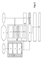
- Fig. 1 provides the first part of the perceptual model used in the calculation of the internal representation of the reference input signal X(t) 3 and the degraded output signal Y(t) 5. Both are scaled 17, 46 and the internal representations 13, 14 in terms of pitch-loudness-time are calculated in a number of steps described below, after which a difference function 12 is calculated, indicated in Fig. 1 with difference calculation operator 7. Two different flavours of the perceptual difference function are calculated, one for the overall disturbance introduced by the system using operators 7 and 8 under test and one for the added parts of the disturbance using operators 9 and 10.
- POLQA starts with the calculation of some basic constant settings after which the pitch power densities (power as function of time and frequency) of reference and degraded are derived from the time and frequency aligned time signals. From the pitch power densities the internal representations of reference and degraded are derived in a number of steps. Furthermore these densities are also used to derive 40 the first three POLQA quality indicators for frequency response distortions 41 (FREQ), additive noise 42 (NOISE) and room reverberations 43 (REVERB). These three quality indicators 41, 42 and 43 are calculated separately from the main disturbance indicator in order to allow a balanced impact analysis over a large range of different distortion types. These indicators can also be used for a more detailed analysis of the type of degradations that were found in the speech signal using a degradation decomposition approach.
- FREQ frequency response distortions 41
- NOISE additive noise 42
- REVERB room reverberations
- the internal representations of the reference 3 are referred to as ideal representations because low levels of noise in the reference are removed (step 33) and timbre distortions as found in the degraded signal that may have resulted from a non optimal timbre of the original reference recordings are partially compensated for (step 35).
- the four different variants of the ideal and degraded internal representations calculated using operators 7, 8, 9 and 10 are used to calculate two final disturbance densities 142 and 143, one representing the final disturbance 142 as a function of time and frequency focussed on the overall degradation and one representing the final disturbance 143 as a function of time and frequency but focussed on the processing of added degradation.
- Fig. 4 gives an overview of the calculation of the MOS-LQO, the objective MOS score, from the two final disturbance densities 142 and 143 and the FREQ 41, NOISE 42, REVERB 43 indicators.
- POLQA operates on three different sample rates, 8, 16, and 48 kHz sampling for which the window size W is set to respectively 256, 512 and 2048 samples in order to match the time analysis window of the human auditory system.
- the overlap between successive frames is 50% using a Hann window.
- the power spectra - the sum of the squared real and squared imaginary parts of the complex FFT components - are stored in separate real valued arrays for both, the reference and the degraded signal. Phase information within a single frame is discarded in POLQA and all calculations are based on the power representations, only.
- the start and stop points used in the POLQA processing are calculated from the beginning and end of the reference file.
- the sum of five successive absolute sample values (using the normal 16 bits PCM range -+32,000) must exceed 500 from the beginning and end of the original speech file in order for that position to be designated as the start or end.
- the interval between this start and end is defined as the active processing interval. Distortions outside this interval are ignored in the POLQA processing.
- a sine wave with a frequency of 1000 Hz and an amplitude of 40 dB SPL is generated, using a reference signal X(t) calibration towards 73 dB SPL.
- This sine wave is transformed to the frequency domain using a windowed FFT in steps 18 and 49 with a length determined by the sampling frequency for X(t) and Y(t) respectively.
- the peak amplitude of the resulting pitch power density is then normalized to a power value of 10 4 by multiplication with a power scaling factor SP 20 and 55 for X(t) and Y(t) respectively.
- the same 40 dB SPL reference tone is used to calibrate the psychoacoustic (Sone) loudness scale. After warping the intensity axis to a loudness scale using Zwicker's law the integral of the loudness density over the Bark frequency scale is normalized in 30 and 58 to 1 Sone using the loudness scaling factor SL 31 and 59 for X(t) and Y(t) respectively.
- the degraded signal Y(t) 5 is multiplied 46 by the calibration factor C 47, that takes care of the mapping from dB overload in the digital domain to dB SPL in the acoustic domain, and then transformed 49 to the time-frequency domain with 50% overlapping FFT frames.
- the reference signal X(t) 3 is scaled 17 towards a predefined fixed optimal level of about 73 dB SPL equivalent before it's transformed 18 to the time-frequency domain. This calibration procedure is fundamentally different from the one used in PESQ where both the degraded and reference are scaled towards predefined fixed optimal level.
- PESQ pre-supposes that all play out is carried out at the same optimal playback level while in the POLQA subjective tests levels between 20 dB to +6 to relative to the optimal level are used. In the POLQA perceptual model one can thus not use a scaling towards a predefined fixed optimal level.
- the reference and degraded signal are transformed 18, 49 to the time-frequency domain using the windowed FFT approach.
- a dewarping in the frequency domain is carried out on the FFT frames.
- both the reference and degraded FFT power spectra are preprocessed to reduce the influence of both very narrow frequency response distortions, as well as overall spectral shape differences on the following calculations.
- the preprocessing 77 may consists in smoothing, compressing and flattening the power spectrum.
- the smoothing operation is performed using a sliding window average in 78 of the powers over the FFT bands, while the compression is done by simply taking the logarithm 79 of the smoothed power in each band.
- the overall shape of the power spectrum is further flattened by performing sliding window normalization in 80 of the smoothed log powers over the FFT bands.
- the pitches of the current reference and degraded frame are computed using a stochastic subharmonic pitch algorithm.
- the ratio 74 of the reference to degraded pitch ration is then used to determine (in step 84) a range of possible warping factors. If possible, this search range is extended by using the pitch ratios for the preceding and following frame pair.
- the frequency align algorithm then iterates through the search range and warps 85 the degraded power spectrum with the warping factor of the current iteration, and processes 88 the warped power spectrum using the preprocessing 77 described above.
- the correlation of the processed reference and processed warped degraded spectrum is then computed (in step 89) for bins below 1500 Hz.
- the "best" (i.e. that resulted in the highest correlation) warping factor is retrieved in step 90.
- the correlation of the processed reference and best warped degraded spectra is then compared against the correlation of the original processed reference and degraded spectra.
- the "best" warping factor is then kept 97 if the correlation increases by a set threshold. If necessary, the warping factor is limited in 98 by a maximum relative change to the warping factor determined for the previous frame pair.
- the frequency scale in Hz is warped in steps 21 and 54 towards the pitch scale in Bark reflecting that at low frequencies, the human hearing system has a finer frequency resolution than at high frequencies.
- This is implemented by binning FFT bands and summing the corresponding powers of the FFT bands with a normalization of the summed parts.
- the warping function that maps the frequency scale in Hertz to the pitch scale in Bark approximates the values given in the literature for this purpose, and known to the skilled reader.
- the resulting reference and degraded signals are known as the pitch power densities PPX(f) n (not indicated in Fig. 1 ) and PPY(f) n 56 with f the frequency in Bark and the index n representing the frame index.
- POLQA operates on three classes of frames, which are distinguished in step 25:
- step 40 The global impact of frequency response distortions, noise and room reverberations is separately quantified in step 40.
- an indicator 41 is calculated from the average spectra of reference and degraded signals.
- the average noise spectrum density of the degraded over the silent frames of the reference signal is subtracted from the pitch loudness density of the degraded signal.
- the resulting pitch loudness density of the degraded and the pitch loudness density of the reference are then averaged in each Bark band over all speech active frames for the reference and degraded file.
- the difference in pitch loudness density between these two densities is then integrated over the pitch to derive the indicator 41 for quantifying the impact of frequency response distortions (FREQ).
- an indicator 42 is calculated from the average spectrum of the degraded signal over the silent frames of the reference signal. The difference between the average pitch loudness density of the degraded over the silent frames and a zero reference pitch loudness density determines a noise loudness density function that quantifies the impact of additive noise. This noise loudness density function is then integrated over the pitch to derive an average noise impact indicator 42 (NOISE).
- NOISE average noise impact indicator
- the energy over time function (ETC) is calculated from the reference and degraded time series.
- the level alignment is carried out to suppress global and local gain differences between the reference and degraded signal.
- the impulse response h(t) is calculated from H(f) using the inverse discrete Fourier transform.
- the ETC is calculated from the absolute values of h(t) through normalization and clipping.
- the loudest reflection is calculated by simply determining the maximum value of the ETC curve after the direct sound.
- direct sound is defined as all sounds that arrive within 60 ms.
- a second loudest reflection is determined over the interval without the direct sound and without taking into account reflections that arrive within 100 ms from the loudest reflection.
- the third loudest reflection is determined over the interval without the direct sound and without taking into account reflections that arrive within 100 ms from the loudest and second loudest reflection.
- the energies and delays of the three loudest reflections are then combined into a single reverb indicator 43 (REVERB).
- the reference signal is now in accordance with step 17 at the internal ideal level, i.e. about 73 dB SPL equivalent, while the degraded signal is represented at a level that coincides with the playback level as a result of 46.
- the global level difference is compensated in step 26.
- small changes in local level are partially compensated to account for the fact that small enough level variations are not noticeable to subjects in a listening-only situation.
- the global level equalization 26 is carried out on the basis of the average power of reference and degraded signal using the frequency components between 400 and 3500 Hz.
- the reference signal is globally scaled towards the degraded signal and the impact of the global playback level difference is thus maintained at this stage of processing.
- a local scaling is carried out for level changes up to about 3 dB using the full bandwidth of both the reference and degraded speech file.
- a partial compensation approach is used in step 27.
- the reference signal is partially filtered with the transfer characteristics of the system under test. This is carried out by calculating the average power spectrum of the original and degraded pitch power densities over all speech active frames. Per Bark bin, a partial compensation factor is calculated 27 from the ratio of the degraded spectrum to the original spectrum.
- Masking is modelled in steps 30 and 58 by calculating a smeared representation of the pitch power densities. Both time and frequency domain smearing are taken into account in accordance with the principles illustrated in Fig. 5a through 5c .
- the time-frequency domain smearing uses the convolution approach. From this smeared representation, the representations of the reference and degraded pitch power density are re-calculated suppressing low amplitude time-frequency components, which are partially masked by neighbouring loud components in the in the time-frequency plane. This suppression is implemented in two different manners, a subtraction of the smeared representation from the non-smeared representation and a division of the non-smeared representation by the smeared representation.
- the resulting two dimensional arrays LX(f) n and LY(f) n are called pitch loudness densities, at the output of step 30 for the reference signal X(t) and step 58 for the degraded signal Y(t) respectively.
- step 33 Low levels of noise in the reference signal, which are not affected by the system under test (e.g., a transparent system) will be attributed to the system under test by subjects due to the absolute category rating test procedure. These low levels of noise thus have to be suppressed in the calculation of the internal representation of the reference signal.
- This "idealization process” is carried out in step 33 by calculating the average steady state noise loudness density of the reference signal LX(f) n over the super silent frames as a function of pitch. This average noise loudness density is then partially subtracted from all pitch loudness density frames of the reference signal. The result is an idealized internal representation of the reference signal, at the output of step 33.
- Steady state noise that is audible in the degraded signal has a lower impact than non-steady state noise. This holds for all levels of noise and the impact of this effect can be modelled by partially removing steady state noise from the degraded signal. This is carried out in step 60 by calculating the average steady state noise loudness density of the degraded signal LY(f) n frames for which the corresponding frame of the reference signal is classified as super silent, as a function of pitch. This average noise loudness density is then partially subtracted from all pitch loudness density frames of the degraded signal.
- the partial compensation uses a different strategy for low and high levels of noise. For low levels of noise the compensation is only marginal while the suppression that is used becomes more aggressive for loud additive noise.
- the result is an internal representation 61 of the degraded signal with an additive noise that is adapted to the subjective impact as observed in listening tests using an idealized noise free representation of the reference signal.
- the LOUDNESS indicator 32 is determined for each of the reference signal frames.
- the LOUDNESS indicator or LOUDNESS value may be used to determine a loudness dependent weighting factor for weighing specific types of distortions.
- the weighing itself may be implemented in steps 125 and 125' for the four representations of distortions provided by operators 7, 8, 9 and 10, upon providing the final disturbance densities 142 and 143.
- the loudness level indicator has been determined in step 33, but one may appreciate that the loudness level indicator may be determined for each reference signal frame in another part of the method.
- determining the loudness level indicator is possible due to the fact that already the average steady state noise loud density is determined for reference signal LX(f) n over the super silent frames, which are then used in the construction of the noise free reference signal for all reference frames.
- this in step 33 it is not the most preferred manner of implementation.
- the loudness level indicator may be taken from the reference signal in an additional step following step 35.
- This additional step is also indicated in figure 1 as a dotted box 35' with dotted line output (LOUDNESS) 32'. If implemented there in step 35', it is no longer necessary to take the loudness level indicator from step 33, as the skilled reader may appreciate.
- step 34 the reference is compensated in step 34 for signal levels where the degraded signal loudness is less than the reference signal loudness
- second the degraded is compensated in step 63 for signal levels where the reference signal loudness is less than the degraded signal loudness.
- the first compensation 34 scales the reference signal towards a lower level for parts of the signal where the degraded shows a severe loss of signal such as in time clipping situations.
- the scaling is such that the remaining difference between reference and degraded represents the impact of time clips on the local perceived speech quality. Parts where the reference signal loudness is less than the degraded signal loudness are not compensated and thus additive noise and loud clicks are not compensated in this first step.
- the second compensation 63 scales the degraded signal towards a lower level for parts of the signal where the degraded signal shows clicks and for parts of the signal where there is noise in the silent intervals.
- the scaling is such that the remaining difference between reference and degraded represents the impact of clicks and slowly changing additive noise on the local perceived speech quality. While clicks are compensated in both the silent and speech active parts, the noise is compensated only in the silent parts.
- Imperceptible linear frequency response distortions were already compensated by partially filtering the reference signal in the pitch power density domain in step 27.
- the reference signal is now partially filtered in step 35 in the pitch loudness domain. This is carried out by calculating the average loudness spectrum of the original and degraded pitch loudness densities over all speech active frames. Per Bark bin, a partial compensation factor is calculated from the ratio of the degraded loudness spectrum to the original loudness spectrum. This partial compensation factor is used to filter the reference signal with smoothed, lower amplitude, version of the frequency response of the system under test. After this filtering, the difference between the reference and degraded pitch loudness densities that result from linear frequency response distortions is diminished to a level that represents the impact of linear frequency response distortions on the perceived speech quality.
- the resulting signals 13 and 14 are now in the perceptual relevant internal representation domain and from the ideal pitch-loudness-time LX ideal(f) n 13 and degraded pitch-loudness-time LY deg (f) n 14 functions the disturbance densities 142 and 143 can be calculated.
- Four different variants of the ideal and degraded pitch-loudness-time functions are calculated in 7, 8, 9 and 10, two variants (7 and 8) focussed on the disturbances for normal and big distortions, and two (9 and 10) focussed on the added disturbances for normal and big distortions.
- the first one is derived in 7 and 8 from the difference between the ideal pitch-loudness-time LX ideal (f) n and degraded pitch-loudness-time function LY deg (f) n .
- the second one is derived in 9 and 10 from the ideal pitch-loudness-time and the degraded pitch-loudness-time function using versions that are optimized with regard to introduced degradations and is called added disturbance.
- signal parts where the degraded power density is larger than the reference power density are weighted with a factor dependent on the power ratio in each pitch-time cell, the asymmetry factor.
- Severe deviations of the optimal listening level are quantified in 127 and 127' by an indicator directly derived from the signal level of the degraded signal. This global indicator (LEVEL) is also used in the calculation of the MOS-LQO.
- Severe distortions introduced by frame repeats are quantified 128 and 128' by an indicator derived from a comparison of the correlation of consecutive frames of the reference signal with the correlation of consecutive frames of the degraded signal.
- Severe deviations from the optimal "ideal" timbre of the degraded signal are quantified 129 and 129' by an indicator derived from the difference in loudness between an upper frequency band and a lower frequency band.
- a timbre indicator is calculated from the difference in loudness in the Bark bands between 2 and 12 Bark in the low frequency part and 7-17 Bark in the upper range. (i.e. using a 5 Bark overlap) of the degraded signal which "punishes" any severe imbalances irrespective of the fact that this could be the result of an incorrect voice timbre of the reference speech file. Compensations are carried out per frame and on a global level. This compensation calculates the power in the lower and upper Bark bands (below 12 and above 7 Bark, i.e.
- the impact of severe peaks in the disturbance is quantified in 130 and 130' in the FLATNESS indicator which is also used in the calculation of the MOS-LQO.
- Severe noise level variations which focus the attention of subjects towards the noise are quantified in 131 and 131' by a noise contrast indicator derived from the degraded signal frames for which the corresponding reference signal frames are silent.
- a weighting operation is performed for weighing disturbances dependent on whether or not they coincide with the actual spoken voice.
- disturbances which are perceived during silent periods are not considered to be as detrimental as disturbances which are perceived during actual spoken voice. Therefore, based on the LOUDNESS indicator determined in step 33 (or alternatively step 35') from the reference signal, a weighting value is determined for weighing any disturbances. The weighting value is used for weighing the difference function (i.e. disturbances) for incorporating the impact of the disturbances on the quality of the degraded speech signal into the evaluation.
- the weighting value may be represented by a loudness dependent function.
- the loudness dependent weighting value may be determined by comparing the loudness value to a threshold. If the loudness indicator exceeds the threshold the perceived disturbances are fully taken in consideration when performing the evaluation. On the other hand, if the loudness value is smaller than the threshold, the weighting value is made dependent on the loudness level indicator; i.e. in the present example the weighting value is equal to the loudness level indicator (in the regime where LOUDNESS is below the threshold).
- the added disturbance is compensated in step 161 for loud reverberations and loud additive noise using the REVERB 42 and NOISE 43 indicators.
- the two disturbances are then combined 170 with the frequency indicator 41 (FREQ) to derive an internal indicator that is linearized with a third order regression polynomial to get a MOS like intermediate indicator 171.
- the raw POLQA score is derived from the MOS like intermediate indicator using four different compensations all in step 175:
- the raw POLQA MOS scores 176 are mapped in 180 towards the MOS-LQO scores 181' using a third order polynomial that is optimized for the 62 databases as were available in the final stage of the POLQA standardization.
- the scores 181' obtained from step 180 may be compensated for some specific type of disturbances.
- the MOS-LQO score may be multiplied by the CVC compensation factor 270 (which may be calculated as indicated below).
- a high band noise compensation factor i.e.
- MOS noise compensation factor CF noise, high_f MOS noise compensation factor CF noise, high_f in accordance with the present invention may be subtracted in step 183 to provide the MOS-LQO at the output 181.
- the high band noise compensation factor CF noise, high_f as calculated in the embodiment of figure 7 described further below is scaled such as to use CF noise, high_f for substracting it from score 181' (or optionally, from the compensated output of step 182 as indicated in figure 4 ), in a different embodiment the high band noise compensation factor may be provided as a multiplier for the score instead.
- the POLQA method may include a consonant-vowel-consonant compensation, which may be implemented as follows.
- reference signal frame 220 and degraded signal frame 240 may be obtained as indicated.
- reference signal frame 220 may be obtained from the warping to bark step 21 of the reference signal, while the degraded signal frame may be obtained from the corresponding step 54 performed for the degraded signal.
- the exact location where the reference signal frame and/or the degraded signal frame are obtained from the method of the invention, as indicated in figure 1 is merely an example.
- the reference signal frame 220 and the degraded signal frame 240 may be obtained from any of the other steps in figure 1 , in particular somewhere between the input of reference signal X(t) 3 and the global and local scaling to the degraded level in step 26.
- the degraded signal frame may be obtained anywhere in between the input of the degraded signal Y(t) 5 and step 54.
- the signal power of the reference signal frame 220 is calculated within the desired frequency domain.
- this frequency domain in the most optimal situation includes only the speech signal (for example the frequency range between 300 hertz and 3500 hertz).
- a selection is performed as to whether or not to include this reference signal frame as an active speech reference signal frame by comparing the calculated signal power to a first threshold 228 and a second threshold 229.
- the first threshold may for example be equal to 7,0 x 10 4 when using a scaling of the reference signal as described in POLQA (ITU-T rec.
- the reference signal frames are selected for processing which correspond to the soft speech reference signal (the critical part of the consonant), by comparing the calculated signal power to a third threshold 230 and a fourth threshold 231.
- the third threshold 230 may for example be equal to 2.0 x 10 7 and the fourth threshold may be equal to 7,0 x 10 7
- Steps 224 and 225 yield the reference signal frames that correspond to the active speech and soft speech parts, respectively the active speech reference signal part frames 234 and the soft speech reference signal parts frames 235. These frames are provided to step 260 to be discussed below.
- the degraded signal frames 240 are first, in step 242, analysed for calculating the signal power in the desired frequency domain.
- the signal power for the degraded signal frames, it will be advantageous to calculate the signal power within a frequency range including the spoken voice frequency range and the frequency range wherein most of the audible noise is present, for example the frequency range between 300 hertz and 8000 hertz.
- the relevant frames are selected, i.e. the frames that are associated with the relevant reference frames. Selection takes place in steps 244 and 245.In step 245, for each degraded signal frame it is determined whether or not it is time aligned with a reference signal frame that is selected in step 225 as a soft speech reference signal frame. If the degraded frame is time aligned with a soft speech reference signal frame, the degraded frame is identified as a soft speech degraded signal frame, and the calculated signal power will be used in the calculation in step 260. Otherwise, the frame is discarded as soft speech degraded signal frame for calculation of the compensation factor in step 247.
- step 244 for each degraded signal frame it is determined whether or not it is time aligned with a reference signal frame that is selected in step 224 as an active speech reference signal frame. If the degraded frame is time aligned with an active speech reference signal frame, the degraded frame is identified as an active speech degraded signal frame, and the calculated signal power will be used in the calculation in step 260. Otherwise, the frame is discarded as active speech degraded signal frame for calculation of the compensation factor in step 247. This yields the soft speech degraded signal parts frames 254 and the active speech degraded signal parts frames 255 which are provided to step 260.
- Step 260 receives as input the active speech reference signal parts frames 234, the soft speech reference signal part frames 235, the soft speech degraded signal parts frames 254 and the active speech degraded signal parts frames 255.
- the parameters ⁇ 1 and ⁇ 2 are constant values that are used to adapt the behavior of the model to the behavior of subjects.
- the other parameters in this formula are as follows: P active, ref, average is the average active speech reference signal part signal power.
- the parameter P soft, ref, average is the average soft speech reference signal part signal power.
- the parameter P active, degraded, average is the average active speech degraded signal part signal power, and the parameter Psoft, degraded, average is the average soft speech degraded signal part signal power.
- CVC SNR_factor the consonant-vowel-consenant signal-to-noise ratio compensation parameter
- the compensation factor 270 thus provided is used in step 182 of figure 4 as a multiplier for the MOS-LQO score (i.e. the overall quality parameter).
- compensation does not necessarily have to take place in step 182, but may be integrated in either one of steps 175 or 180 (in which case step 182 disappears from the scheme of figure 4 ).
- compensation is achieved by multiplying the MOS-LQO score by the compensation factor calculated as indicated above. It will be appreciated that compensation may take another form as well. For example, it may also be possible to subtract or add a variable to the obtained MOS-LQO dependent on the CVC SNR_factor . The skilled person will appreciate and recognize other meanings of compensation in line with the present teaching.
- the POLQA method further includes a compensation of the MOS-LQO score such as to properly address the impact of noise in the upper frequency range, i.e. above 3000 Hz.
- ITU-T recommendation P.863 - POLQA - allows prediction of speech quality in a wide range of distortions. However with certain types of advanced speech signal processing the impact of some distortions are not predicted correctly.
- the present invention addresses this problem by compensating the MOS-LQO score.
- One problem is the impact of noise in so called empty speech bands. In situations where the speech bandwidth is lower than the bandwidth of the masking noise, the impact of the noise on the perceived speech quality is not correctly predicted.
- compensation of the MOS-LQO is less critical in situations where the speech signal also has a significant non-zero component in the frequency range above 3000 Hz.
- This invention allows correct prediction of the impact of noise as found in frequency bands where no or little speech energy is found.
- the best known example is the adaptation of the narrowband speech signal as found is standard definition speech transmission (bandwidth 50-3500 Hz) towards the use of these signals in environments with a wideband masking noise background.
- Other examples are the mixing of standard definition narrowband speech with high definition wideband speech (bandwidth 50-7000 Hz) in audio conferencing.
- a correction factor 300 that is used to correct the final Objective Mean Opinion Score (MOS-LQO) in step 183 as is outputted by POLQA P.863.
- the compensation may also be used more generally in any prediction model made by an objective speech quality measurement system.
- the invention may be applied to compensate the earlier prediction models PSQM (ITU-T Rec. P.861, 1996) or PESQ (ITU-T Rec. P.862, 2000).
- the embodiment described herein may be conveniently used for correcting these predicted scores by providing a compensation factor (i.e. high band noise level compensation factor) that may be subtracted from the obtained predicted score. This factor may be computed as follows.
- the reference speech file is used to determine the set of silent frames where no, or marginal, speech activity is found, in the aligned degraded speech file.
- identifying silent frames and super silent frames of the reference signal frames is done in step 25 of figure 1 .
- the silent frames and/or super silent frames (either one or the other, or both) may be used as candidate frames 275 for use in step 277 of figure 7 .
- These candidate frames 275 and the degraded signal frames 240 are input to the identification step 277.
- the degraded signal frames are either classified as silent degraded signal frames 279 or non-silent degraded signal frames 280.
- This classification of the degraded signal frames 240 is based on whether or not a degraded signal frame 240 at the input of step 277 is associated by the frame pairs obtained in step 6 to a reference signal frame that is classified as a candidate frame 275 as determined in step 25.
- step 282 for all silent frames 279 of the degraded signal, the amount of noise in the upper frequency bands is determined (above 3000 Hz), and from this set of frames the average noise level in the upper bands is determined.
- This may be established in step 282 by computing the signal power of these silent frames above the frequency threshold of 3000 Hz, summing all signal powers of all silent frames, and dividing by the number of silent frames to establish the average signal power of the silent frames as a noise level parameter value (P noise, degr, high_f, aver ).
- the noise level parameter value 286 may be maximized by threshold value MAX 283 to prevent overcompensation of the MOS score later.
- the threshold value 283 MAX may for example be set at 2.0 in the present embodiment; however, any desired maximum of the noise level parameter value 286 (e.g. 1.5 ⁇ MAX ⁇ 2.5) may be used. Step 285 may be dispensed with if desired. The noise level parameter value 286 will be used as input to steps 288 and 295.
- step 284 for all non-silent frames 280, the amount of energy in the upper frequency bands is determined (above the frequency threshold; e.g. 3000 Hz), and from this set of frames the average active level in the upper bands is determined.
- the average active level can be determined in step 284 similarly as is done in step 282 for the average noise level: by computing the signal power of these non-silent (i.e. speech active) frames above the frequency threshold (3000 Hz), summing all signal powers of all non-silent speech active frames, and dividing by the number of speech active frames to establish the average signal power of the speech active frames as an active level parameter value 287 (P active, degr, high_f, aver).
- P active degr, high_f, aver
- step 288 by subtracting from the average active level 287 in the upper bands of the speech active frames the average noise level 286 in the upper bands of the silent frames.
- MIN lower bound
- MOS noise compensation factor CF noise, high_f 300 is subtracted in step 183 of figure 4 from the Objective Mean Opinion Score MOS-LQO as is outputted by POLQA to obtain the corrected MOS-LQO 181 that shows a better correlation with the subjectively perceived speech quality.
- the high band noise impact compensation with the parameters as indicated hereinabove for the embodiment described has been tuned and optimized such as to compensate the MOS LQO score for the impact of high band noise on the assessment of quality of the degraded signal.
- the high band noise impact compensation could be likewise applied to compensate the MOS LQO score for the impact of high band noise on the assessment of intelligibility.
- Intelligibility and quality of a degraded speech signal are to be distinguished from each other in that these properties are being assessed differently as perceived by a human. Where quality relates to the audio signal itself, intelligibility relates to transfer of information. Therefore, a different optimisation of the parameters of the high band noise impact compensation is to be used in case it the compensation is applied to the assessment of intelligibility.
- the exemplary parameter values and multipliers such as the frequency threshold, the lower bound (MIN) of the high band difference value ⁇ P high_f , the upper bound (MAX) of the noise level parameter value P noise, degr, high_f, aver, or the multiplier constant (1.2 above) used for calculating the weighting value w, may take different values depending on the application.
- the frequency threshold may be selected between 2500 Hz and 4000 Hz, preferably 2700 Hz and 4000 Hz, although both for intelligibility assessment as well as quality assessment, good results have been obtained using 3000 Hz.
- the lower bound (MIN) of the high band difference value ⁇ P high_f may be between 8.0 ⁇ MIN ⁇ 11.0; for quality assessment an optimum was found at 11.0, while for intelligibility assessment the optimum was found at 9.0.
- the upper bound (MAX) of the noise level parameter value Pnoise, degr, high_f aver may be between 1.0 ⁇ MAX ⁇ 3.0; for quality assessment an optimum was found at 2.0, while for intelligibility assessment the optimum was found at 1.5.
Priority Applications (5)
| Application Number | Priority Date | Filing Date | Title |
|---|---|---|---|
| EP14160914.9A EP2922058A1 (de) | 2014-03-20 | 2014-03-20 | Verfahren und Vorrichtung zur Bewertung der Qualität eines verschlechterten Sprachsignals |
| EP15715496.4A EP3120356B1 (de) | 2014-03-20 | 2015-03-19 | Verfahren und vorrichtung zur bewertung der qualität eines verschlechterten sprachsignals |
| US15/127,077 US9953663B2 (en) | 2014-03-20 | 2015-03-19 | Method of and apparatus for evaluating quality of a degraded speech signal |
| PCT/NL2015/050175 WO2015142175A1 (en) | 2014-03-20 | 2015-03-19 | Method of and apparatus for evaluating quality of a degraded speech signal |
| CN201580022707.5A CN106663450B (zh) | 2014-03-20 | 2015-03-19 | 用于评估劣化语音信号的质量的方法及装置 |
Applications Claiming Priority (1)
| Application Number | Priority Date | Filing Date | Title |
|---|---|---|---|
| EP14160914.9A EP2922058A1 (de) | 2014-03-20 | 2014-03-20 | Verfahren und Vorrichtung zur Bewertung der Qualität eines verschlechterten Sprachsignals |
Publications (1)
| Publication Number | Publication Date |
|---|---|
| EP2922058A1 true EP2922058A1 (de) | 2015-09-23 |
Family
ID=50336167
Family Applications (2)
| Application Number | Title | Priority Date | Filing Date |
|---|---|---|---|
| EP14160914.9A Withdrawn EP2922058A1 (de) | 2014-03-20 | 2014-03-20 | Verfahren und Vorrichtung zur Bewertung der Qualität eines verschlechterten Sprachsignals |
| EP15715496.4A Active EP3120356B1 (de) | 2014-03-20 | 2015-03-19 | Verfahren und vorrichtung zur bewertung der qualität eines verschlechterten sprachsignals |
Family Applications After (1)
| Application Number | Title | Priority Date | Filing Date |
|---|---|---|---|
| EP15715496.4A Active EP3120356B1 (de) | 2014-03-20 | 2015-03-19 | Verfahren und vorrichtung zur bewertung der qualität eines verschlechterten sprachsignals |
Country Status (4)
| Country | Link |
|---|---|
| US (1) | US9953663B2 (de) |
| EP (2) | EP2922058A1 (de) |
| CN (1) | CN106663450B (de) |
| WO (1) | WO2015142175A1 (de) |
Cited By (3)
| Publication number | Priority date | Publication date | Assignee | Title |
|---|---|---|---|---|
| US20140316773A1 (en) * | 2011-11-17 | 2014-10-23 | Nederlandse Organisatie Voor Toegepast-Natuurwetenschappelijk Onderzoek Tno | Method of and apparatus for evaluating intelligibility of a degraded speech signal |
| US20140324419A1 (en) * | 2011-11-17 | 2014-10-30 | Nederlandse Organisatie voor toegepast-natuurwetenschappelijk oaderzoek TNO | Method of and apparatus for evaluating intelligibility of a degraded speech signal |
| US10490206B2 (en) | 2016-01-19 | 2019-11-26 | Dolby Laboratories Licensing Corporation | Testing device capture performance for multiple speakers |
Families Citing this family (6)
| Publication number | Priority date | Publication date | Assignee | Title |
|---|---|---|---|---|
| GB201621434D0 (en) * | 2016-12-16 | 2017-02-01 | Palantir Technologies Inc | Processing sensor logs |
| CN108986831B (zh) * | 2017-05-31 | 2021-04-20 | 南宁富桂精密工业有限公司 | 语音干扰滤除的方法、电子装置及计算机可读存储介质 |
| CN109903752B (zh) * | 2018-05-28 | 2021-04-20 | 华为技术有限公司 | 对齐语音的方法和装置 |
| CN111986693A (zh) * | 2020-08-10 | 2020-11-24 | 北京小米松果电子有限公司 | 音频信号的处理方法及装置、终端设备和存储介质 |
| CN113689883B (zh) * | 2021-08-18 | 2022-11-01 | 杭州雄迈集成电路技术股份有限公司 | 语音质量评估方法、系统、计算机可读存储介质 |
| CN117711419B (zh) * | 2024-02-05 | 2024-04-26 | 卓世智星(成都)科技有限公司 | 用于数据中台的数据智能清洗方法 |
Citations (2)
| Publication number | Priority date | Publication date | Assignee | Title |
|---|---|---|---|---|
| EP2595146A1 (de) * | 2011-11-17 | 2013-05-22 | Nederlandse Organisatie voor toegepast -natuurwetenschappelijk onderzoek TNO | Verfahren und Vorrichtung zur Untersuchung der Verständlichkeit eines verrauschten Sprachsignals |
| EP2595145A1 (de) * | 2011-11-17 | 2013-05-22 | Nederlandse Organisatie voor toegepast -natuurwetenschappelijk onderzoek TNO | Verfahren und Vorrichtung zur Untersuchung der Verständlichkeit eines verrauschten Sprachsignals |
Family Cites Families (23)
| Publication number | Priority date | Publication date | Assignee | Title |
|---|---|---|---|---|
| CA2230188A1 (en) * | 1998-03-27 | 1999-09-27 | William C. Treurniet | Objective audio quality measurement |
| EP1241663A1 (de) * | 2001-03-13 | 2002-09-18 | Koninklijke KPN N.V. | Verfahren und Vorrichtung zur Sprachqualitätsbestimmung |
| CA2354755A1 (en) * | 2001-08-07 | 2003-02-07 | Dspfactory Ltd. | Sound intelligibilty enhancement using a psychoacoustic model and an oversampled filterbank |
| US7308403B2 (en) * | 2002-07-01 | 2007-12-11 | Lucent Technologies Inc. | Compensation for utterance dependent articulation for speech quality assessment |
| US7353002B2 (en) * | 2003-08-28 | 2008-04-01 | Koninklijke Kpn N.V. | Measuring a talking quality of a communication link in a network |
| CN100347988C (zh) * | 2003-10-24 | 2007-11-07 | 武汉大学 | 一种宽频带语音质量客观评价方法 |
| PT1792304E (pt) * | 2004-09-20 | 2008-12-04 | Tno | Compensação de frequência para análise de percepção de voz |
| WO2006136900A1 (en) * | 2005-06-15 | 2006-12-28 | Nortel Networks Limited | Method and apparatus for non-intrusive single-ended voice quality assessment in voip |
| US7856355B2 (en) * | 2005-07-05 | 2010-12-21 | Alcatel-Lucent Usa Inc. | Speech quality assessment method and system |
| FR2894707A1 (fr) * | 2005-12-09 | 2007-06-15 | France Telecom | Procede de mesure de la qualite percue d'un signal audio degrade par la presence de bruit |
| EP2002429B1 (de) * | 2006-04-04 | 2012-11-21 | Dolby Laboratories Licensing Corporation | Steuerung von einer charakteristik der wahrgenommenen lautstärke eines audiosignals |
| ATE516580T1 (de) * | 2008-01-14 | 2011-07-15 | Ericsson Telefon Ab L M | Objektive messung der audioqualität |
| EP2438591B1 (de) * | 2009-06-04 | 2013-08-21 | Telefonaktiebolaget LM Ericsson (publ) | Verfahren und anordnung zur schätzung der qualitätsverschlechterung eines verarbeiteten signals |
| ES2526126T3 (es) * | 2009-08-14 | 2015-01-07 | Koninklijke Kpn N.V. | Método, producto de programa informático y sistema para determinar una calidad percibida de un sistema de audio |
| US8818798B2 (en) * | 2009-08-14 | 2014-08-26 | Koninklijke Kpn N.V. | Method and system for determining a perceived quality of an audio system |
| CN102044247B (zh) * | 2009-10-10 | 2012-07-04 | 北京理工大学 | 一种针对VoIP语音的客观评测方法 |
| CN102044248B (zh) * | 2009-10-10 | 2012-07-04 | 北京理工大学 | 一种针对流媒体音频质量的客观评测方法 |
| JP5606764B2 (ja) * | 2010-03-31 | 2014-10-15 | クラリオン株式会社 | 音質評価装置およびそのためのプログラム |
| US8583423B2 (en) * | 2010-05-17 | 2013-11-12 | Telefonaktiebolaget L M Ericsson (Publ) | Method and arrangement for processing of speech quality estimate |
| BR112014007481A2 (pt) * | 2011-09-29 | 2017-04-04 | Dolby Int Ab | detecção de alta qualidade em sinais de rádio fm estéreo |
| JP5782402B2 (ja) * | 2012-03-29 | 2015-09-24 | 日本電信電話株式会社 | 音声品質客観評価装置及び方法 |
| US8942109B2 (en) * | 2012-04-25 | 2015-01-27 | Anritsu Company | Impairment simulation for network communication to enable voice quality degradation estimation |
| CN103632680B (zh) * | 2012-08-24 | 2016-08-10 | 华为技术有限公司 | 一种语音质量评估方法、网元及系统 |
-
2014
- 2014-03-20 EP EP14160914.9A patent/EP2922058A1/de not_active Withdrawn
-
2015
- 2015-03-19 WO PCT/NL2015/050175 patent/WO2015142175A1/en active Application Filing
- 2015-03-19 CN CN201580022707.5A patent/CN106663450B/zh active Active
- 2015-03-19 US US15/127,077 patent/US9953663B2/en active Active
- 2015-03-19 EP EP15715496.4A patent/EP3120356B1/de active Active
Patent Citations (2)
| Publication number | Priority date | Publication date | Assignee | Title |
|---|---|---|---|---|
| EP2595146A1 (de) * | 2011-11-17 | 2013-05-22 | Nederlandse Organisatie voor toegepast -natuurwetenschappelijk onderzoek TNO | Verfahren und Vorrichtung zur Untersuchung der Verständlichkeit eines verrauschten Sprachsignals |
| EP2595145A1 (de) * | 2011-11-17 | 2013-05-22 | Nederlandse Organisatie voor toegepast -natuurwetenschappelijk onderzoek TNO | Verfahren und Vorrichtung zur Untersuchung der Verständlichkeit eines verrauschten Sprachsignals |
Non-Patent Citations (1)
| Title |
|---|
| BEERENDS JOHN G ET AL: "Perceptual Objective Listening Quality Assessment (POLQA), The Third Generation ITU-T Standard for End-to-End Speech Quality Measurement Part II-Perceptual M", JAES, AES, 60 EAST 42ND STREET, ROOM 2520 NEW YORK 10165-2520, USA, vol. 61, no. 6, 8 July 2013 (2013-07-08), pages 385 - 402, XP040633056 * |
Cited By (4)
| Publication number | Priority date | Publication date | Assignee | Title |
|---|---|---|---|---|
| US20140316773A1 (en) * | 2011-11-17 | 2014-10-23 | Nederlandse Organisatie Voor Toegepast-Natuurwetenschappelijk Onderzoek Tno | Method of and apparatus for evaluating intelligibility of a degraded speech signal |
| US20140324419A1 (en) * | 2011-11-17 | 2014-10-30 | Nederlandse Organisatie voor toegepast-natuurwetenschappelijk oaderzoek TNO | Method of and apparatus for evaluating intelligibility of a degraded speech signal |
| US9659579B2 (en) * | 2011-11-17 | 2017-05-23 | Nederlandse Organisatie Voor Toegepast-Natuurwetenschappelijk Onderzoek Tno | Method of and apparatus for evaluating intelligibility of a degraded speech signal, through selecting a difference function for compensating for a disturbance type, and providing an output signal indicative of a derived quality parameter |
| US10490206B2 (en) | 2016-01-19 | 2019-11-26 | Dolby Laboratories Licensing Corporation | Testing device capture performance for multiple speakers |
Also Published As
| Publication number | Publication date |
|---|---|
| EP3120356A1 (de) | 2017-01-25 |
| CN106663450A (zh) | 2017-05-10 |
| US9953663B2 (en) | 2018-04-24 |
| CN106663450B (zh) | 2021-02-02 |
| US20170117006A1 (en) | 2017-04-27 |
| EP3120356B1 (de) | 2018-05-02 |
| WO2015142175A1 (en) | 2015-09-24 |
Similar Documents
| Publication | Publication Date | Title |
|---|---|---|
| EP3120356B1 (de) | Verfahren und vorrichtung zur bewertung der qualität eines verschlechterten sprachsignals | |
| EP2780909B1 (de) | Verfahren und vorrichtung zur untersuchung der verständlichkeit eines verrauschten sprachsignals | |
| US9472202B2 (en) | Method of and apparatus for evaluating intelligibility of a degraded speech signal | |
| US8818798B2 (en) | Method and system for determining a perceived quality of an audio system | |
| EP2048657B1 (de) | Verfahren und System zur Messung der Sprachverständlichkeit eines Tonübertragungssystems | |
| EP2780910B1 (de) | Verfahren und vorrichtung zur untersuchung der verständlichkeit eines verrauschten sprachsignals | |
| EP3944240A1 (de) | Verfahren zur bestimmung des wahrnehmbaren einflusses von nachhall auf die wahrgenommene qualität eines signals sowie computerprogrammprodukt |
Legal Events
| Date | Code | Title | Description |
|---|---|---|---|
| PUAI | Public reference made under article 153(3) epc to a published international application that has entered the european phase |
Free format text: ORIGINAL CODE: 0009012 |
|
| AK | Designated contracting states |
Kind code of ref document: A1 Designated state(s): AL AT BE BG CH CY CZ DE DK EE ES FI FR GB GR HR HU IE IS IT LI LT LU LV MC MK MT NL NO PL PT RO RS SE SI SK SM TR |
|
| AX | Request for extension of the european patent |
Extension state: BA ME |
|
| STAA | Information on the status of an ep patent application or granted ep patent |
Free format text: STATUS: THE APPLICATION IS DEEMED TO BE WITHDRAWN |
|
| 18D | Application deemed to be withdrawn |
Effective date: 20160324 |