EP2922052A1 - Method and apparatus for determining encoding mode, method and apparatus for encoding audio signals, and method and apparatus for decoding audio signals - Google Patents
Method and apparatus for determining encoding mode, method and apparatus for encoding audio signals, and method and apparatus for decoding audio signals Download PDFInfo
- Publication number
- EP2922052A1 EP2922052A1 EP13854639.5A EP13854639A EP2922052A1 EP 2922052 A1 EP2922052 A1 EP 2922052A1 EP 13854639 A EP13854639 A EP 13854639A EP 2922052 A1 EP2922052 A1 EP 2922052A1
- Authority
- EP
- European Patent Office
- Prior art keywords
- encoding mode
- encoding
- initial
- mode
- unit
- Prior art date
- Legal status (The legal status is an assumption and is not a legal conclusion. Google has not performed a legal analysis and makes no representation as to the accuracy of the status listed.)
- Granted
Links
- 230000005236 sound signal Effects 0.000 title claims abstract description 70
- 238000000034 method Methods 0.000 title claims abstract description 53
- 230000005284 excitation Effects 0.000 claims description 81
- 238000001228 spectrum Methods 0.000 claims description 46
- 238000012937 correction Methods 0.000 claims description 9
- 206010019133 Hangover Diseases 0.000 claims description 7
- 238000012545 processing Methods 0.000 description 18
- 238000010586 diagram Methods 0.000 description 17
- 238000007781 pre-processing Methods 0.000 description 10
- 238000002474 experimental method Methods 0.000 description 9
- 239000000203 mixture Substances 0.000 description 9
- 238000004088 simulation Methods 0.000 description 9
- 230000003595 spectral effect Effects 0.000 description 6
- 230000002123 temporal effect Effects 0.000 description 6
- 230000007774 longterm Effects 0.000 description 4
- 230000003044 adaptive effect Effects 0.000 description 3
- 230000001934 delay Effects 0.000 description 3
- 238000012805 post-processing Methods 0.000 description 3
- 230000001755 vocal effect Effects 0.000 description 3
- 230000000694 effects Effects 0.000 description 2
- 230000003287 optical effect Effects 0.000 description 2
- 230000005540 biological transmission Effects 0.000 description 1
- 238000013500 data storage Methods 0.000 description 1
- 230000006870 function Effects 0.000 description 1
- 239000011159 matrix material Substances 0.000 description 1
- 230000011664 signaling Effects 0.000 description 1
- 238000012549 training Methods 0.000 description 1
- 230000001052 transient effect Effects 0.000 description 1
Images


Classifications
-
- G—PHYSICS
- G10—MUSICAL INSTRUMENTS; ACOUSTICS
- G10L—SPEECH ANALYSIS OR SYNTHESIS; SPEECH RECOGNITION; SPEECH OR VOICE PROCESSING; SPEECH OR AUDIO CODING OR DECODING
- G10L19/00—Speech or audio signals analysis-synthesis techniques for redundancy reduction, e.g. in vocoders; Coding or decoding of speech or audio signals, using source filter models or psychoacoustic analysis
- G10L19/005—Correction of errors induced by the transmission channel, if related to the coding algorithm
-
- G—PHYSICS
- G10—MUSICAL INSTRUMENTS; ACOUSTICS
- G10L—SPEECH ANALYSIS OR SYNTHESIS; SPEECH RECOGNITION; SPEECH OR VOICE PROCESSING; SPEECH OR AUDIO CODING OR DECODING
- G10L19/00—Speech or audio signals analysis-synthesis techniques for redundancy reduction, e.g. in vocoders; Coding or decoding of speech or audio signals, using source filter models or psychoacoustic analysis
- G10L19/04—Speech or audio signals analysis-synthesis techniques for redundancy reduction, e.g. in vocoders; Coding or decoding of speech or audio signals, using source filter models or psychoacoustic analysis using predictive techniques
- G10L19/16—Vocoder architecture
- G10L19/18—Vocoders using multiple modes
- G10L19/22—Mode decision, i.e. based on audio signal content versus external parameters
-
- G—PHYSICS
- G10—MUSICAL INSTRUMENTS; ACOUSTICS
- G10L—SPEECH ANALYSIS OR SYNTHESIS; SPEECH RECOGNITION; SPEECH OR VOICE PROCESSING; SPEECH OR AUDIO CODING OR DECODING
- G10L19/00—Speech or audio signals analysis-synthesis techniques for redundancy reduction, e.g. in vocoders; Coding or decoding of speech or audio signals, using source filter models or psychoacoustic analysis
- G10L19/04—Speech or audio signals analysis-synthesis techniques for redundancy reduction, e.g. in vocoders; Coding or decoding of speech or audio signals, using source filter models or psychoacoustic analysis using predictive techniques
- G10L19/08—Determination or coding of the excitation function; Determination or coding of the long-term prediction parameters
- G10L19/12—Determination or coding of the excitation function; Determination or coding of the long-term prediction parameters the excitation function being a code excitation, e.g. in code excited linear prediction [CELP] vocoders
-
- G—PHYSICS
- G10—MUSICAL INSTRUMENTS; ACOUSTICS
- G10L—SPEECH ANALYSIS OR SYNTHESIS; SPEECH RECOGNITION; SPEECH OR VOICE PROCESSING; SPEECH OR AUDIO CODING OR DECODING
- G10L19/00—Speech or audio signals analysis-synthesis techniques for redundancy reduction, e.g. in vocoders; Coding or decoding of speech or audio signals, using source filter models or psychoacoustic analysis
- G10L19/04—Speech or audio signals analysis-synthesis techniques for redundancy reduction, e.g. in vocoders; Coding or decoding of speech or audio signals, using source filter models or psychoacoustic analysis using predictive techniques
-
- G—PHYSICS
- G10—MUSICAL INSTRUMENTS; ACOUSTICS
- G10L—SPEECH ANALYSIS OR SYNTHESIS; SPEECH RECOGNITION; SPEECH OR VOICE PROCESSING; SPEECH OR AUDIO CODING OR DECODING
- G10L19/00—Speech or audio signals analysis-synthesis techniques for redundancy reduction, e.g. in vocoders; Coding or decoding of speech or audio signals, using source filter models or psychoacoustic analysis
- G10L19/04—Speech or audio signals analysis-synthesis techniques for redundancy reduction, e.g. in vocoders; Coding or decoding of speech or audio signals, using source filter models or psychoacoustic analysis using predictive techniques
- G10L19/16—Vocoder architecture
- G10L19/18—Vocoders using multiple modes
- G10L19/20—Vocoders using multiple modes using sound class specific coding, hybrid encoders or object based coding
Definitions
- Apparatuses and methods consistent with exemplary embodiments relate to audio encoding and decoding, and more particularly, to a method and an apparatus for determining an encoding mode for improving the quality of a reconstructed audio signal, by determining an encoding mode appropriate to characteristics of an audio signal and preventing frequent encoding mode switching, a method and an apparatus for encoding an audio signal, and a method and an apparatus for decoding an audio signal.
- aspects of one or more exemplary embodiments provide a method and an apparatus for determining an encoding mode for improving the quality of a reconstructed audio signal, by determining an encoding mode appropriate to characteristics of an audio signal, a method and an apparatus for encoding an audio signal, and a method and an apparatus for decoding an audio signal.
- aspects of one or more exemplary embodiments provide a method and an apparatus for determining an encoding mode appropriate to characteristics of an audio signal and reducing delays due to frequent encoding mode switching, a method and an apparatus for encoding an audio signal, and a method and an apparatus for decoding an audio signal.
- a method of determining an encoding mode including determining one from among a plurality of encoding modes including a first encoding mode and a second encoding mode as an initial encoding mode in correspondence to characteristics of an audio signal, and if there is an error in the determination of the initial encoding mode, generating a corrected encoding mode by correcting the initial encoding mode to a third encoding mode.
- a method of encoding an audio signal including determining one from among a plurality of encoding modes including a first encoding mode and a second encoding mode as an initial encoding mode in correspondence to characteristics of an audio signal, if there is an error in the determination of the initial encoding mode, generating a corrected encoding mode by correcting the initial encoding mode to a third encoding mode, and performing different encoding processes on the audio signal based on either the initial encoding mode or the corrected encoding mode.
- a method of decoding an audio signal including parsing a bitstream comprising one of an initial encoding mode obtained by determining one from among a plurality of encoding modes including a first encoding mode and a second encoding mode in correspondence to characteristics of an audio signal and a third encoding mode corrected from the initial encoding mode if there is an error in the determination of the initial encoding mode, and performing different decoding processes on the bitstream based on either the initial encoding mode or the third encoding mode.
- an encoding mode adaptive to characteristics of an audio signal may be selected while preventing frequent encoding mode switching between frames.
- each unit described in exemplary embodiments are independently illustrated to indicate different characteristic functions, and it does not mean that each unit is formed of one separate hardware or software component.
- Each unit is illustrated for the convenience of explanation, and a plurality of units may form one unit, and one unit may be divided into a plurality of units.
- FIG. 1 is a block diagram illustrating a configuration of an audio encoding apparatus 100 according to an exemplary embodiment.
- the audio encoding apparatus 100 shown in FIG. 1 may include an encoding mode determining unit 110, a switching unit 120, a spectrum domain encoding unit 130, a linear prediction domain encoding unit 140, and a bitstream generating unit 150.
- the linear prediction domain encoding unit 140 may include a time domain excitation encoding unit 141 and a frequency domain excitation encoding unit 143, where the linear prediction domain encoding unit 140 may be embodied as at least one of the two excitation encoding units 141 and 143.
- the above-stated components may be integrated into at least one module and may be implemented as at least one processor (not shown).
- the term of an audio signal may refer to a music signal, a speech signal, or a mixed signal thereof.
- the encoding mode determining unit 110 may analyze characteristics of an audio signal to determine the class of the audio signal, and determine an encoding mode in correspondence to a result of the classification.
- the determining of the encoding mode may be performed in units of superframes, frames, or bands.
- the determining of the encoding mode may be performed in units of a plurality of superframe groups, a plurality of frame groups, or a plurality of band groups.
- examples of the encoding modes may include a spectrum domain and a time domain or a linear prediction domain, but are not limited thereto.
- the encoding mode determining unit 110 may determine an initial encoding mode of an audio signal as one of a spectrum domain encoding mode and a time domain encoding mode. According to another exemplary embodiment, the encoding mode determining unit 110 may determine an initial encoding mode of an audio signal as one of a spectrum domain encoding mode, a time domain excitation encoding mode and a frequency domain excitation encoding mode.
- the encoding mode determining unit 110 may correct the initial encoding mode to one of the spectrum domain encoding mode and the frequency domain excitation encoding mode. If the time domain encoding mode, that is, the time domain excitation encoding mode is determined as the initial encoding mode, the encoding mode determining unit 110 may correct the initial encoding mode to one of the time domain excitation encoding mode and the frequency domain excitation encoding mode. If the time domain excitation encoding mode is determined as the initial encoding mode, the determination of the final encoding mode may be selectively performed. In other words, the initial encoding mode, that is, the time domain excitation encoding mode may be maintained.
- the encoding mode determining unit 110 may determine encoding modes of a plurality of frames corresponding to a hangover length, and may determine the final encoding mode for a current frame. According to an exemplary embodiment, if the initial encoding mode or a corrected encoding mode of a current frame is identical to encoding modes of a plurality of previous frames, e.g., 7 previous frames, the corresponding initial encoding mode or corrected encoding mode may be determined as the final encoding mode of the current frame.
- the encoding mode determining unit 110 may determine the encoding mode of the frame just before the current frame as the final encoding mode of the current frame.
- an encoding mode adaptive to characteristics of an audio signal may be selected while preventing frequent encoding mode switching between frames.
- the time domain encoding that is, the time domain excitation encoding may be efficient for a speech signal
- the spectrum domain encoding may be efficient for a music signal
- the frequency domain excitation encoding may be efficient for a vocal and/or harmonic signal.
- the switching unit 120 may provide an audio signal to either the spectrum domain encoding unit 130 or the linear prediction domain encoding unit 140. If the linear prediction domain encoding unit 140 is embodied as the time domain excitation encoding unit 141, the switching unit 120 may include total two branches. If the linear prediction domain encoding unit 140 is embodied as the time domain excitation encoding unit 141 and the frequency domain excitation encoding unit 143, the switching unit 120 may have total 3 branches.
- the spectrum domain encoding unit 130 may encode an audio signal in the spectrum domain.
- the spectrum domain may refer to the frequency domain or a transform domain.
- Examples of coding methods applicable to the spectrum domain encoding unit 130 may include an advance audio coding (AAC), or a combination of a modified discrete cosine transform (MDCT) and a factorial pulse coding (FPC), but are not limited thereto.
- AAC advance audio coding
- MDCT modified discrete cosine transform
- FPC factorial pulse coding
- other quantizing techniques and entropy coding techniques may be used instead of the FPC. It may be efficient to encode a music signal in the spectrum domain encoding unit 130.
- the linear prediction domain encoding unit 140 may encode an audio signal in a linear prediction domain.
- the linear prediction domain may refer to an excitation domain or a time domain.
- the linear prediction domain encoding unit 140 may be embodied as the time domain excitation encoding unit 141 or may be embodied to include the time domain excitation encoding unit 141 and the frequency domain excitation encoding unit 143.
- Examples of coding methods applicable to the time domain excitation encoding unit 141 may include code excited linear prediction (CELP) or an algebraic CELP (ACELP), but are not limited thereto.
- Examples of coding methods applicable to the frequency domain excitation encoding unit 143 may include general signal coding (GSC) or transform coded excitation (TCX), are not limited thereto. It may be efficient to encode a speech signal in the time domain excitation encoding unit 141, whereas it may be efficient to encode a vocal and/or harmonic signal in the frequency domain excitation encoding unit 143.
- the bitstream generating unit 150 may generate a bitstream to include the encoding mode provided by the encoding mode determining unit 110, a result of encoding provided by the spectrum domain encoding unit 130, and a result of encoding provided by the linear prediction domain encoding unit 140.
- FIG. 2 is a block diagram illustrating a configuration of an audio encoding apparatus 200 according to another exemplary embodiment.
- the audio encoding apparatus 200 shown in FIG. 2 may include a common pre-processing module 205, an encoding mode determining unit 210, a switching unit 220, a spectrum domain encoding unit 230, a linear prediction domain encoding unit 240, and a bitstream generating unit 250.
- the linear prediction domain encoding unit 240 may include a time domain excitation encoding unit 241 and a frequency domain excitation encoding unit 243, and the linear prediction domain encoding unit 240 may be embodied as either the time domain excitation encoding unit 241 or the frequency domain excitation encoding unit 243.
- the audio encoding apparatus 200 may further include the common pre-processing module 205, and thus descriptions of components identical to those of the audio encoding apparatus 100 will be omitted.
- the common pre-processing module 205 may perform joint stereo processing, surround processing, and/or bandwidth extension processing.
- the joint stereo processing, the surround processing, and the bandwidth extension processing may be identical to those employed by a specific standard, e.g., the MPEG standard, but are not limited thereto.
- Output of the common pre-processing module 205 may be in a mono channel, a stereo channel, or multi channels.
- the switching unit 220 may include at least one switch. For example, if the common pre-processing module 205 outputs a signal of two or more channels, that is, a stereo channel or a multi-channel, switches corresponding to the respective channels may be arranged.
- the first channel of a stereo signal may be a speech channel
- the second channel of the stereo signal may be a music channel.
- an audio signal may be simultaneously provided to the two switches.
- Additional information generated by the common pre-processing module 205 may be provided to the bitstream generating unit 250 and included in a bitstream.
- the additional information may be necessary for performing the joint stereo processing, the surround processing, and/or the bandwidth extension processing in a decoding end and may include spatial parameters, envelope information, energy information, etc.
- the bandwidth extension processing may be differently performed based on encoding domains.
- the audio signal in a core band may be processed by using the time domain excitation encoding mode or the frequency domain excitation encoding mode, whereas an audio signal in a bandwidth extended band may be processed in the time domain.
- the bandwidth extension processing in the time domain may include a plurality of modes including a voiced mode or an unvoiced mode.
- an audio signal in the core band may be processed by using the spectrum domain encoding mode, whereas an audio signal in the bandwidth extended band may be processed in the frequency domain.
- the bandwidth extension processing in the frequency domain may include a plurality of modes including a transient mode, a normal mode, or a harmonic mode.
- an encoding mode determined by the encoding mode determining unit 110 may be provided to the common pre-processing module 205 as a signaling information.
- the last portion of the core band and the beginning portion of the bandwidth extended band may overlap each other to some extent. Location and size of the overlapped portions may be set in advance.
- FIG. 3 is a block diagram illustrating a configuration of an encoding mode determining unit 300 according to an exemplary embodiment.
- the encoding mode determining unit 300 shown in FIG. 3 may include an initial encoding mode determining unit 310 and an encoding mode correcting unit 330.
- the initial encoding mode determining unit 310 may determine whether an audio signal is a music signal or a speech signal by using feature parameters extracted from the audio signal. If the audio signal is determined as a speech signal, linear prediction domain encoding may be suitable. Meanwhile, if the audio signal is determined as a music signal, spectrum domain encoding may be suitable. The initial encoding mode determining unit 310 may determine the class of the audio signal indicating whether spectrum domain encoding, time domain excitation encoding, or frequency domain excitation encoding is suitable for the audio signal by using feature parameters extracted from the audio signal. A corresponding encoding mode may be determined based on the class of the audio signal. If a switching unit (120 of FIG.
- the initial encoding mode determining unit 310 may determine whether an audio signal is a music signal or a speech signal by using any of various techniques known in the art. Examples thereof may include FD/LPD classification or ACELP/TCX classification disclosed in an encoder part of the USAC standard and ACELP/TCX classification used in the AMR standards, but are not limited thereto. In other words, the initial encoding mode may be determined by using any of various methods other than the method according to embodiments described herein.
- the encoding mode correcting unit 330 may determine a corrected encoding mode by correcting the initial encoding mode determined by the initial encoding mode determining unit 310 by using correction parameters. According to an exemplary embodiment, if the spectrum domain encoding mode is determined as the initial encoding mode, the initial encoding mode may be corrected to the frequency domain excitation encoding mode based on correction parameters. If the time domain encoding mode is determined as the initial encoding mode, the initial encoding mode may be corrected to the frequency domain excitation encoding mode based on correction parameters. In other words, it is determined whether there is an error in determination of the initial encoding mode by using correction parameters.
- the initial encoding mode may be maintained. On the contrary, if it is determined that there is an error in the determination of the initial encoding mode, the initial encoding mode may be corrected.
- the correction of the initial encoding mode may be obtained from the spectrum domain encoding mode to the frequency domain excitation encoding mode and from the time domain excitation encoding mode to frequency domain excitation encoding mode.
- the initial encoding mode or the corrected encoding mode may be a temporary encoding mode for a current frame, where the temporary encoding mode for the current frame may be compared to encoding modes for previous frames within a preset hangover length and the final encoding mode for the current frame may be determined.
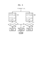
- FIG. 4 is a block diagram illustrating a configuration of an initial encoding mode determining unit 400 according to an exemplary embodiment.
- the initial encoding mode determining unit 400 shown in FIG. 4 may include a feature parameter extracting unit 410 and a determining unit 430.
- the feature parameter extracting unit 410 may extract feature parameters necessary for determining an encoding mode from an audio signal.
- the extracted feature parameters include at least one or two from among a pitch parameter, a voicing parameter, a correlation parameter, and a linear prediction error, but are not limited thereto. Detailed descriptions of individual parameters will be given below.
- a first feature parameter F 1 relates to a pitch parameter, where a behavior of pitch may be determined by using N pitch values detected in a current frame and at least one previous frame.
- M pitch values significantly different from the average of the N pitch values may be removed.
- N and M may be values obtained via experiments or simulations in advance.
- N may be set in advance, and a difference between a pitch value to be removed and the average of the N pitch values may be determined via experiments or simulations in advance.
- the first feature parameter F 1 may be expressed as shown in Equation 1 below by using the average m p' and the variance ⁇ p' with respect to (N-M) pitch values.
- F 1 ⁇ p ⁇ m p ⁇
- a second feature parameter F 2 also relates to a pitch parameter and may indicate reliability of a pitch value detected in a current frame.
- the second feature parameter F 2 may be expressed as shown in Equation 2 bellow by using variances ⁇ SF1 and ⁇ SF2 of pitch values respectively detected in two sub-frames SF 1 and SF 2 of a current frame.
- F 2 cov S F 1 , S F 2 ⁇ S F 1 ⁇ ⁇ S F 2
- cov(SF 1 ,SF 2 ) denotes the covariance between the sub-frames SF 1 and SF 2 .
- the second feature parameter F 2 indicates correlation between two sub-frames as a pitch distance.
- a current frame may include two or more sub-frames, and Equation 2 may be modified based on the number of sub-frames.
- a third feature parameter F 3 may be expressed as shown in Equation 3 below based on a voicing parameter voicing and a correlation parameter Corr.
- F 3 Q ⁇ c Voincing - Corr C 2 N
- the voicing parameter Voicing relates to vocal features of sound and may be obtained any of various methods known in the art, whereas the correlation parameter Corr may be obtained by summing correlations between frames for each band.
- a fourth feature parameter F 4 relates to a linear prediction error E LPC and may be expressed as shown in Equation 4 below.
- F 4 E L P C i - M E L P C 2 N
- M(E LPC ) denotes the average of N linear prediction errors.
- the determining unit 430 may determine the class of an audio signal by using at least one feature parameter provided by the feature parameter extracting unit 410 and may determine the initial encoding mode based on the determined class.
- the determining unit 430 may employ soft decision mechanism, where at least one mixture may be formed per feature parameter.
- the class of an audio signal may be determined by using the Gaussian mixture model (GMM) based on mixture probabilities.
- GMM Gaussian mixture model
- a probability f(x) regarding one mixture may be calculated according to Equation 5 below.
- x denotes an input vector of a feature parameter
- m denotes a mixture
- c denotes a covariance matrix
- the determining unit 430 may calculate a music probability Pm and a speech probability Ps by using Equation 6 below.
- P m Q i b M ⁇ p i
- P s Q i b S ⁇ p i
- the music probability Pm may be calculated by adding probabilities Pi of M mixtures related to feature parameters superior for music determination
- the speech probability Ps may be calculated by adding probabilities Pi of S mixtures related to feature parameters superior for speech determination.
- the music probability Pm and the speech probability Ps may be calculated according to Equation 7 below.
- P m Q i b M ⁇ p i ⁇ 1 - p i e r r + Q i b S ⁇ p i p i e r r
- P s Q i b S ⁇ p i ⁇ 1 - p i e r + Q i b M ⁇ p i p i e r r
- p i err denotes error probability of each mixture.
- the error probability may be obtained by classifying training data incuding clean speech signals and clean music signals using each of mixtures and counting the number of wrong classifications.
- the probability P M that all frames include music signals only and the speech probability P S that all frames include speech signals only with respect to a plurality of frames as many as a constant hangover length may be calculated according to Equation 8 below.
- the hangover length may be set to 8, but is not limited thereto.
- Eight frames may include a current frame and 7 previous frames.
- a plurality of conditions sets D i M and D i S may be calculated by using the music probability Pm or the speech probability Ps obtained using Equation 5 or Equation 6. Detailed descriptions thereof will be given below with reference to FIG.
- each condition has a value 1 for music and has a value 0 for speech.
- a sum of music conditions M and a sum of voice conditions S may be obtained from the plurality of condition sets D i M and D i S that are calculated by using the music probability Pm and the speech probability Ps.
- the sum of music conditions M and the sum of speech conditions S may be expressed as shown in Equation 9 below.
- the sum of music conditions M is compared to a designated threshold value Tm. If the sum of music conditions M is greater than the threshold value Tm, an encoding mode of a current frame is switched to a music mode, that is, the spectrum domain encoding mode. If the sum of music conditions M is smaller than or equal to the threshold value Tm, the encoding mode of the current frame is not changed.
- the sum of speech conditions S is compared to a designated threshold value Ts. If the sum of speech conditions S is greater than the threshold value Ts, an encoding mode of a current frame is switched to a speech mode, that is, the linear prediction domain encoding mode. If the sum of speech conditions S is smaller than or equal to the threshold value Ts, the encoding mode of the current frame is not changed.
- the threshold value Tm and the threshold value Ts may be set to values obtained via experiments or simulations in advance.
- FIG. 5 is a block diagram illustrating a configuration of a feature parameter extracting unit 500 according to an exemplary embodiment.
- An initial encoding mode determining unit 500 shown in FIG. 5 may include a transform unit 510, a spectral parameter extracting unit 520, a temporal parameter extracting unit 530, and a determining unit 540.
- the transform unit 510 may transform an original audio signal from the time domain to the frequency domain.
- the transform unit 510 may apply any of various transform techniques for representing an audio signal from a time domain to a spectrum domain. Examples of the techniques may include fast Fourier transform (FFT), discrete cosine transform (DCT), or modified discrete cosine transform (MDCT), but are not limited thereto.
- FFT fast Fourier transform
- DCT discrete cosine transform
- MDCT modified discrete cosine transform
- the spectral parameter extracting unit 520 may extract at least one spectral parameter from a frequency domain audio signal provided by the transform unit 510.
- Spectral parameters may be categorized into short-term feature parameters and long-term feature parameters.
- the short-term feature parameters may be obtained from a current frame, whereas the long-term feature parameters may be obtained from a plurality of frames including the current frame and at least one previous frame.
- the temporal parameter extracting unit 530 may extract at least one temporal parameter from a time domain audio signal.
- Temporal parameters may also be categorized into short-term feature parameters and long-term feature parameters.
- the short-term feature parameters may be obtained from a current frame, whereas the long-term feature parameters may be obtained from a plurality of frames including the current frame and at least one previous frame.
- a determining unit (430 of FIG. 4 ) may determine the class of an audio signal by using spectral parameters provided by the spectral parameter extracting unit 520 and temporal parameters provided by the temporal parameter extracting unit 530 and may determine the initial encoding mode based on the determined class.
- the determining unit (430 of FIG. 4 ) may employ soft decision mechanism.
- FIG. 7 is a diagram illustrating an operation of an encoding mode correcting unit 310 according to an exemplary embodiment.
- an initial encoding mode determined by the initial encoding mode determining unit 310 is received and it may be determined whether the encoding mode is the time domain mode, that is, the time domain excitation mode or the spectrum domain mode.
- an index state TTSS indicating whether the frequency domain excitation encoding is more appropriate may be checked.
- the index state TTSS indicating whether the frequency domain excitation encoding (e.g., GSC) is more appropriate may be obtained by using tonalities of different frequency bands. Detailed descriptions thereof will be given below.
- Tonality of a low band signal may be obtained as a ratio between a sum of a plurality of spectrum coefficients having small values including the smallest value and the spectrum coefficient having the largest value with respect to a given band. If given bands are 0 ⁇ 1 kHz, 1 ⁇ 2 kHz, and 2 ⁇ 4 kHz, tonalities t 01 , t 12 , and t 24 of the respective bands and tonality t L of a low band signal, that is, the core band may be expressed as shown in Equation 10 below.
- the linear prediction error err may be obtained by using a linear prediction coding (LPC) filter and may be used to remove strong tonal components.
- LPC linear prediction coding
- the spectrum domain encoding mode may be more efficient with respect to strong tonal components than the frequency domain excitation encoding mode.
- a front condition cond front for switching to the frequency domain excitation encoding mode by using the tonalities and the linear prediction error obtained as described above may be expressed as shown in Equation 11 below.
- cond front t 12 > t 12 ⁇ front and t 24 > t 24 ⁇ front and t L > t Lfront and err > err front
- t 12front , t 24front , t Lfront , and err front are threshold values and may have values obtained via experiments or simulations in advance.
- Equation 12 a back condition cond back for finishing the frequency domain excitation encoding mode by using the tonalities and the linear prediction error obtained as described above may be expressed as shown in Equation 12 below.
- cond back t 12 ⁇ t 12 ⁇ back and t 24 ⁇ t 24 ⁇ back and t L ⁇ t Lback
- t 12back , t 24back , t Lback are threshold values and may have values obtained via experiments or simulations in advance.
- the index state TTSS indicating whether the frequency domain excitation encoding (e.g., GSC) is more appropriate than the spectrum domain encoding is 1 by determining whether the front condition shown in Equation 11 is satisfied or the back condition shown in Equation 12 is not satisfied.
- the determination of the back condition shown in Equation 12 may be optional.
- the frequency domain excitation encoding mode may be determined as the final encoding mode.
- the spectrum domain encoding mode which is the initial encoding mode, is corrected to the frequency domain excitation encoding mode, which is the final encoding mode.
- an index state SS for determining whether an audio signal includes a strong speech characteristic may be checked. If there is an error in the determination of the spectrum domain encoding mode, the frequency domain excitation encoding mode may be more efficient than the spectrum domain encoding mode.
- the index state SS for determining whether an audio signal includes a strong speech characteristic may be obtained by using a difference vc between a voicing parameter and a correlation parameter.
- a front condition cond front for switching to a strong speech mode by using the difference vc between a voicing parameter and a correlation parameter may be expressed as shown in Equation 13 below.
- cond front v c > v c front
- vc front is a threshold value and may have a value obtained via experiments or simulations in advance.
- a back condition cond back for finishing the strong speech mode by using the difference vc between a voicing parameter and a correlation parameter may be expressed as shown in Equation 14 below.
- vc back is a threshold value and may have a value obtained via experiments or simulations in advance.
- an operation 705 it may be determined whether the index state SS indicating whether the frequency domain excitation encoding (e.g. GSC) is more appropriate than the spectrum domain encoding is 1 by determining whether the front condition shown in Equation 13 is satisfied or the back condition shown in Equation 14 is not satisfied.
- the determination of the back condition shown in Equation 14 may be optional.
- the spectrum domain encoding mode may be determined as the final encoding mode.
- the spectrum domain encoding mode which is the initial encoding mode, is maintained as the final encoding mode.
- the frequency domain excitation encoding mode may be determined as the final encoding mode.
- the spectrum domain encoding mode which is the initial encoding mode, is corrected to the frequency domain excitation encoding mode, which is the final encoding mode.
- an error in the determination of the spectrum domain encoding mode as the initial encoding mode may be corrected.
- the spectrum domain encoding mode which is the initial encoding mode, may be maintained or switched to the frequency domain excitation encoding mode as the final encoding mode.
- an index state SM for determining whether an audio signal includes a strong music characteristic may be checked. If there is an error in the determination of the linear prediction domain encoding mode, that is, the time domain excitation encoding mode, the frequency domain excitation encoding mode may be more efficient than the time domain excitation encoding mode.
- the state SM for determining whether an audio signal includes a strong music characteristic may be obtained by using a value 1-vc obtained by subtracting the difference vc between a voicing parameter and a correlation parameter from 1.
- a front condition cond front for switching to a strong music mode by using the value 1-vc obtained by subtracting the difference vc between a voicing parameter and a correlation parameter from 1 may be expressed as shown in Equation 15 below.
- cond front 1 - v c > v c m front
- vcm front is a threshold value and may have a value obtained via experiments or simulations in advance.
- vcm back is a threshold value and may have a value obtained via experiments or simulations in advance.
- an operation 709 it may be determined whether the index state SM indicating whether the frequency domain excitation encoding (e.g. GSC) is more appropriate than the time domain excitation encoding is 1 by determining whether the front condition shown in Equation 15 is satisfied or the back condition shown in Equation 16 is not satisfied.
- the determination of the back condition shown in Equation 16 may be optional.
- the time domain excitation encoding mode may be determined as the final encoding mode.
- the linear prediction domain encoding mode which is the initial encoding mode, is switched to the time domain excitation encoding mode as the final encoding mode.
- it may be considered that the initial encoding mode is maintained without changes, if the linear prediction domain encoding mode corresponds to the time domain excitation encoding mode.
- the frequency domain excitation encoding mode may be determined as the final encoding mode.
- the linear prediction domain encoding mode which is the initial encoding mode
- the frequency domain excitation encoding mode which is the final encoding mode
- the linear prediction domain encoding mode (e.g., the time domain excitation encoding mode), which is the initial encoding mode, may be maintained or switched to the frequency domain excitation encoding mode as the final encoding mode.
- the operation 709 for determining whether the audio signal includes a strong music characteristic for correcting an error in the determination of the linear prediction domain encoding mode may be optional.
- a sequence of performing the operation 705 for determining whether the audio signal includes a strong speech characteristic and the operation 701 for determining whether the frequency domain excitation encoding mode is appropriate may be reversed.
- the operation 705 may be performed first, and then the operation 701 may be performed.
- parameters used for the determinations may be changed as occasions demand.
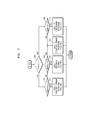
- FIG. 8 is a block diagram illustrating a configuration of an audio decoding apparatus 800 according to an exemplary embodiment.
- the audio decoding apparatus 800 shown in FIG. 8 may include a bitstream parsing unit 810, a spectrum domain decoding unit 820, a linear prediction domain decoding unit 830, and a switching unit 840.
- the linear prediction domain decoding unit 830 may include a time domain excitation decoding unit 831 and a frequency domain excitation decoding unit 833, where the linear prediction domain decoding unit 830 may be embodied as at least one of the time domain excitation decoding unit 831 and the frequency domain excitation decoding unit 833.
- the above-stated components may be integrated into at least one module and may be implemented as at least one processor (not shown).
- the bitstream parsing unit 810 may parse a received bitstream and separate information on an encoding mode and encoded data.
- the encoding mode may correspond to either an initial encoding mode obtained by determining one from among a plurality of encoding modes including a first encoding mode and a second encoding mode in correspondence to characteristics of an audio signal or a third encoding mode corrected from the initial encoding mode if there is an error in the determination of the initial encoding mode.
- the spectrum domain decoding unit 820 may decode data encoded in the spectrum domain from the separated encoded data.
- the linear prediction domain decoding unit 830 may decode data encoded in the linear prediction domain from the separated encoded data. If the linear prediction domain decoding unit 830 includes the time domain excitation decoding unit 831 and the frequency domain excitation decoding unit 833, the linear prediction domain decoding unit 830 may perform time domain excitation decoding or frequency domain exciding decoding with respect to the separated encoded data.
- the switching unit 840 may switch either a signal reconstructed by the spectrum domain decoding unit 820 or a signal reconstructed by the linear prediction domain decoding unit 830 and may provide the switched signal as a final reconstructed signal.
- FIG. 9 is a block diagram illustrating a configuration of an audio decoding apparatus 900 according to another exemplary embodiment.
- the audio decoding apparatus 900 may include a bitstream parsing unit 910, a spectrum domain decoding unit 920, a linear prediction domain decoding unit 930, a switching unit 940, and a common post-processing module 950.
- the linear prediction domain decoding unit 930 may include a time domain excitation decoding unit 931 and a frequency domain excitation decoding unit 933, where the linear prediction domain decoding unit 930 may be embodied as at least one of time domain excitation decoding unit 931 and the frequency domain excitation decoding unit 933.
- the above-stated components may be integrated into at least one module and may be implemented as at least one processor (not shown).
- the audio decoding apparatus 900 may further include the common post-processing module 950, and thus descriptions of components identical to those of the audio decoding apparatus 800 will be omitted.
- the common post-processing module 950 may perform joint stereo processing, surround processing, and/or bandwidth extension processing, in correspondence to a common pre-processing module (205 of FIG. 2 ).
- the methods according to the exemplary embodiments can be written as computer-executable programs and can be implemented in general-use digital computers that execute the programs by using a non-transitory computer-readable recording medium.
- data structures, program instructions, or data files, which can be used in the embodiments can be recorded on a non-transitory computer-readable recording medium in various ways.
- the non-transitory computer-readable recording medium is any data storage device that can store data which can be thereafter read by a computer system.
- non-transitory computer-readable recording medium examples include magnetic storage media, such as hard disks, floppy disks, and magnetic tapes, optical recording media, such as CD-ROMs and DVDs, magneto-optical media, such as optical disks, and hardware devices, such as ROM, RAM, and flash memory, specially configured to store and execute program instructions.
- the non-transitory computer-readable recording medium may be a transmission medium for transmitting signal designating program instructions, data structures, or the like.
- the program instructions may include not only mechanical language codes created by a compiler but also high-level language codes executable by a computer using an interpreter or the like.
Landscapes
- Engineering & Computer Science (AREA)
- Computational Linguistics (AREA)
- Signal Processing (AREA)
- Health & Medical Sciences (AREA)
- Audiology, Speech & Language Pathology (AREA)
- Human Computer Interaction (AREA)
- Physics & Mathematics (AREA)
- Acoustics & Sound (AREA)
- Multimedia (AREA)
- Compression, Expansion, Code Conversion, And Decoders (AREA)
- Transmission Systems Not Characterized By The Medium Used For Transmission (AREA)
Abstract
Description
- Apparatuses and methods consistent with exemplary embodiments relate to audio encoding and decoding, and more particularly, to a method and an apparatus for determining an encoding mode for improving the quality of a reconstructed audio signal, by determining an encoding mode appropriate to characteristics of an audio signal and preventing frequent encoding mode switching, a method and an apparatus for encoding an audio signal, and a method and an apparatus for decoding an audio signal.
- It is widely known that it is efficient to encode a music signal in the frequency domain and it is efficient to encode a speech signal in the time domain. Therefore, various techniques for determining the class of an audio signal, in which the music signal and the speech signal are mixed, and determining an encoding mode in correspondence to the determined class have been suggested.
- However, due to frequency encoding mode switching, not only delays occur, but also decoded sound quality is deteriorated. Furthermore, since there is no technique for correcting a primarily determined encoding mode, i.e. class, if an error occurs during determination of an encoding mode, the quality of a reconstructed audio signal is deteriorated.
- Aspects of one or more exemplary embodiments provide a method and an apparatus for determining an encoding mode for improving the quality of a reconstructed audio signal, by determining an encoding mode appropriate to characteristics of an audio signal, a method and an apparatus for encoding an audio signal, and a method and an apparatus for decoding an audio signal.
- Aspects of one or more exemplary embodiments provide a method and an apparatus for determining an encoding mode appropriate to characteristics of an audio signal and reducing delays due to frequent encoding mode switching, a method and an apparatus for encoding an audio signal, and a method and an apparatus for decoding an audio signal.
- According to an aspect of one or more exemplary embodiments, there is a method of determining an encoding mode, the method including determining one from among a plurality of encoding modes including a first encoding mode and a second encoding mode as an initial encoding mode in correspondence to characteristics of an audio signal, and if there is an error in the determination of the initial encoding mode, generating a corrected encoding mode by correcting the initial encoding mode to a third encoding mode.
- According to an aspect of one or more exemplary embodiments, there is a method of encoding an audio signal, the method including determining one from among a plurality of encoding modes including a first encoding mode and a second encoding mode as an initial encoding mode in correspondence to characteristics of an audio signal, if there is an error in the determination of the initial encoding mode, generating a corrected encoding mode by correcting the initial encoding mode to a third encoding mode, and performing different encoding processes on the audio signal based on either the initial encoding mode or the corrected encoding mode.
- According to an aspect of one or more exemplary embodiments, there is a method of decoding an audio signal, the method including parsing a bitstream comprising one of an initial encoding mode obtained by determining one from among a plurality of encoding modes including a first encoding mode and a second encoding mode in correspondence to characteristics of an audio signal and a third encoding mode corrected from the initial encoding mode if there is an error in the determination of the initial encoding mode, and performing different decoding processes on the bitstream based on either the initial encoding mode or the third encoding mode.
- According to exemplary embodiments, by determining the final encoding mode of a current frame based on correction of the initial encoding mode and encoding modes of frames corresponding to a hangover length, an encoding mode adaptive to characteristics of an audio signal may be selected while preventing frequent encoding mode switching between frames.
-
-
FIG. 1 is a block diagram illustrating a configuration of an audio encoding apparatus according to an exemplary embodiment; -
FIG. 2 is a block diagram illustrating a configuration of an audio encoding apparatus according to another exemplary embodiment; -
FIG. 3 is a block diagram illustrating a configuration of an encoding mode determining unit according to an exemplary embodiment; -
FIG. 4 is a block diagram illustrating a configuration of an initial encoding mode determining unit according to an exemplary embodiment; -
FIG. 5 is a block diagram illustrating a configuration of a feature parameter extracting unit according to an exemplary embodiment; -
FIG. 6 is a diagram illustrating an adaptive switching method between a linear prediction domain encoding and a spectrum domain according to an exemplary embodiment; -
FIG. 7 is a diagram illustrating an operation of an encoding mode correcting unit according to an exemplary embodiment; -
FIG. 8 is a block diagram illustrating a configuration of an audio decoding apparatus according to an exemplary embodiment; and -
FIG. 9 is a block diagram illustrating a configuration of an audio decoding apparatus according to another exemplary embodiment. - Reference will now be made in detail to embodiments, examples of which are illustrated in the accompanying drawings, wherein like reference numerals refer to like elements throughout. In this regard, the present embodiments may have different forms and should not be construed as being limited to the descriptions set forth herein. Accordingly, the embodiments are merely described below, by referring to the figures, to explain aspects of the present description.
- Terms such as "connected" and "linked" may be used to indicate a directly connected or linked state, but it shall be understood that another component may be interposed therebetween.
- Terms such as "first" and "second" may be used to describe various components, but the components shall not be limited to the terms. The terms may be used only to distinguish one component from another component.
- The units described in exemplary embodiments are independently illustrated to indicate different characteristic functions, and it does not mean that each unit is formed of one separate hardware or software component. Each unit is illustrated for the convenience of explanation, and a plurality of units may form one unit, and one unit may be divided into a plurality of units.
-
FIG. 1 is a block diagram illustrating a configuration of anaudio encoding apparatus 100 according to an exemplary embodiment. - The
audio encoding apparatus 100 shown inFIG. 1 may include an encodingmode determining unit 110, aswitching unit 120, a spectrumdomain encoding unit 130, a linear predictiondomain encoding unit 140, and abitstream generating unit 150. The linear predictiondomain encoding unit 140 may include a time domainexcitation encoding unit 141 and a frequency domainexcitation encoding unit 143, where the linear predictiondomain encoding unit 140 may be embodied as at least one of the twoexcitation encoding units - Referring to
FIG. 1 , the encodingmode determining unit 110 may analyze characteristics of an audio signal to determine the class of the audio signal, and determine an encoding mode in correspondence to a result of the classification. The determining of the encoding mode may be performed in units of superframes, frames, or bands. Alternatively, the determining of the encoding mode may be performed in units of a plurality of superframe groups, a plurality of frame groups, or a plurality of band groups. Here, examples of the encoding modes may include a spectrum domain and a time domain or a linear prediction domain, but are not limited thereto. If performance and processing speed of a processor are sufficient and delays due to encoding mode switching may be resolved, encoding modes may be subdivided, and encoding schemes may also be subdivided in correspondence to the encoding mode. According to an exemplary embodiment, the encodingmode determining unit 110 may determine an initial encoding mode of an audio signal as one of a spectrum domain encoding mode and a time domain encoding mode. According to another exemplary embodiment, the encodingmode determining unit 110 may determine an initial encoding mode of an audio signal as one of a spectrum domain encoding mode, a time domain excitation encoding mode and a frequency domain excitation encoding mode. If the spectrum domain encoding mode is determined as the initial encoding mode, the encodingmode determining unit 110 may correct the initial encoding mode to one of the spectrum domain encoding mode and the frequency domain excitation encoding mode. If the time domain encoding mode, that is, the time domain excitation encoding mode is determined as the initial encoding mode, the encodingmode determining unit 110 may correct the initial encoding mode to one of the time domain excitation encoding mode and the frequency domain excitation encoding mode. If the time domain excitation encoding mode is determined as the initial encoding mode, the determination of the final encoding mode may be selectively performed. In other words, the initial encoding mode, that is, the time domain excitation encoding mode may be maintained. The encodingmode determining unit 110 may determine encoding modes of a plurality of frames corresponding to a hangover length, and may determine the final encoding mode for a current frame. According to an exemplary embodiment, if the initial encoding mode or a corrected encoding mode of a current frame is identical to encoding modes of a plurality of previous frames, e.g., 7 previous frames, the corresponding initial encoding mode or corrected encoding mode may be determined as the final encoding mode of the current frame. Meanwhile, if the initial encoding mode or a corrected encoding mode of a current frame is not identical to encoding modes of a plurality of previous frames, e.g., 7 previous frames, the encodingmode determining unit 110 may determine the encoding mode of the frame just before the current frame as the final encoding mode of the current frame. - As described above, by determining the final encoding mode of a current frame based on correction of the initial encoding mode and encoding modes of frames corresponding to a hangover length, an encoding mode adaptive to characteristics of an audio signal may be selected while preventing frequent encoding mode switching between frames.
- Generally, the time domain encoding, that is, the time domain excitation encoding may be efficient for a speech signal, the spectrum domain encoding may be efficient for a music signal, and the frequency domain excitation encoding may be efficient for a vocal and/or harmonic signal.
- In correspondence to an encoding mode determined by the encoding
mode determining unit 110, theswitching unit 120 may provide an audio signal to either the spectrumdomain encoding unit 130 or the linear predictiondomain encoding unit 140. If the linear predictiondomain encoding unit 140 is embodied as the time domainexcitation encoding unit 141, theswitching unit 120 may include total two branches. If the linear predictiondomain encoding unit 140 is embodied as the time domainexcitation encoding unit 141 and the frequency domainexcitation encoding unit 143, theswitching unit 120 may have total 3 branches. - The spectrum
domain encoding unit 130 may encode an audio signal in the spectrum domain. The spectrum domain may refer to the frequency domain or a transform domain. Examples of coding methods applicable to the spectrumdomain encoding unit 130 may include an advance audio coding (AAC), or a combination of a modified discrete cosine transform (MDCT) and a factorial pulse coding (FPC), but are not limited thereto. In detail, other quantizing techniques and entropy coding techniques may be used instead of the FPC. It may be efficient to encode a music signal in the spectrumdomain encoding unit 130. - The linear prediction
domain encoding unit 140 may encode an audio signal in a linear prediction domain. The linear prediction domain may refer to an excitation domain or a time domain. The linear predictiondomain encoding unit 140 may be embodied as the time domainexcitation encoding unit 141 or may be embodied to include the time domainexcitation encoding unit 141 and the frequency domainexcitation encoding unit 143. Examples of coding methods applicable to the time domainexcitation encoding unit 141 may include code excited linear prediction (CELP) or an algebraic CELP (ACELP), but are not limited thereto. Examples of coding methods applicable to the frequency domainexcitation encoding unit 143 may include general signal coding (GSC) or transform coded excitation (TCX), are not limited thereto. It may be efficient to encode a speech signal in the time domainexcitation encoding unit 141, whereas it may be efficient to encode a vocal and/or harmonic signal in the frequency domainexcitation encoding unit 143. - The
bitstream generating unit 150 may generate a bitstream to include the encoding mode provided by the encodingmode determining unit 110, a result of encoding provided by the spectrumdomain encoding unit 130, and a result of encoding provided by the linear predictiondomain encoding unit 140. -
FIG. 2 is a block diagram illustrating a configuration of anaudio encoding apparatus 200 according to another exemplary embodiment. - The
audio encoding apparatus 200 shown inFIG. 2 may include acommon pre-processing module 205, an encodingmode determining unit 210, aswitching unit 220, a spectrumdomain encoding unit 230, a linear predictiondomain encoding unit 240, and abitstream generating unit 250. Here, the linear predictiondomain encoding unit 240 may include a time domainexcitation encoding unit 241 and a frequency domainexcitation encoding unit 243, and the linear predictiondomain encoding unit 240 may be embodied as either the time domainexcitation encoding unit 241 or the frequency domainexcitation encoding unit 243. Compared to theaudio encoding apparatus 100 shown inFIG.1 , theaudio encoding apparatus 200 may further include thecommon pre-processing module 205, and thus descriptions of components identical to those of theaudio encoding apparatus 100 will be omitted. - Referring to
FIG. 2 , thecommon pre-processing module 205 may perform joint stereo processing, surround processing, and/or bandwidth extension processing. The joint stereo processing, the surround processing, and the bandwidth extension processing may be identical to those employed by a specific standard, e.g., the MPEG standard, but are not limited thereto. Output of thecommon pre-processing module 205 may be in a mono channel, a stereo channel, or multi channels. According to the number of channels of an signal output by thecommon pre-processing module 205, theswitching unit 220 may include at least one switch. For example, if thecommon pre-processing module 205 outputs a signal of two or more channels, that is, a stereo channel or a multi-channel, switches corresponding to the respective channels may be arranged. For example, the first channel of a stereo signal may be a speech channel, and the second channel of the stereo signal may be a music channel. In this case, an audio signal may be simultaneously provided to the two switches. Additional information generated by thecommon pre-processing module 205 may be provided to thebitstream generating unit 250 and included in a bitstream. The additional information may be necessary for performing the joint stereo processing, the surround processing, and/or the bandwidth extension processing in a decoding end and may include spatial parameters, envelope information, energy information, etc. However, there may be various additional information based on processing techniques applied thereto. - According to an exemplary embodiment, at the
common pre-processing module 205, the bandwidth extension processing may be differently performed based on encoding domains. The audio signal in a core band may be processed by using the time domain excitation encoding mode or the frequency domain excitation encoding mode, whereas an audio signal in a bandwidth extended band may be processed in the time domain. The bandwidth extension processing in the time domain may include a plurality of modes including a voiced mode or an unvoiced mode. Alternatively, an audio signal in the core band may be processed by using the spectrum domain encoding mode, whereas an audio signal in the bandwidth extended band may be processed in the frequency domain. The bandwidth extension processing in the frequency domain may include a plurality of modes including a transient mode, a normal mode, or a harmonic mode. To perform bandwidth extension processing in different domains, an encoding mode determined by the encodingmode determining unit 110 may be provided to thecommon pre-processing module 205 as a signaling information. According to an exemplary embodiment, the last portion of the core band and the beginning portion of the bandwidth extended band may overlap each other to some extent. Location and size of the overlapped portions may be set in advance. -
FIG. 3 is a block diagram illustrating a configuration of an encodingmode determining unit 300 according to an exemplary embodiment. - The encoding
mode determining unit 300 shown inFIG. 3 may include an initial encodingmode determining unit 310 and an encodingmode correcting unit 330. - Referring to
FIG. 3 , the initial encodingmode determining unit 310 may determine whether an audio signal is a music signal or a speech signal by using feature parameters extracted from the audio signal. If the audio signal is determined as a speech signal, linear prediction domain encoding may be suitable. Meanwhile, if the audio signal is determined as a music signal, spectrum domain encoding may be suitable. The initial encodingmode determining unit 310 may determine the class of the audio signal indicating whether spectrum domain encoding, time domain excitation encoding, or frequency domain excitation encoding is suitable for the audio signal by using feature parameters extracted from the audio signal. A corresponding encoding mode may be determined based on the class of the audio signal. If a switching unit (120 ofFIG. 1 ) has two branches, an encoding mode may be expressed in 1-bit. If the switching unit (120 ofFIG. 1 ) has three branches, an encoding mode may be expressed in 2-bits. The initial encodingmode determining unit 310 may determine whether an audio signal is a music signal or a speech signal by using any of various techniques known in the art. Examples thereof may include FD/LPD classification or ACELP/TCX classification disclosed in an encoder part of the USAC standard and ACELP/TCX classification used in the AMR standards, but are not limited thereto. In other words, the initial encoding mode may be determined by using any of various methods other than the method according to embodiments described herein. - The encoding
mode correcting unit 330 may determine a corrected encoding mode by correcting the initial encoding mode determined by the initial encodingmode determining unit 310 by using correction parameters. According to an exemplary embodiment, if the spectrum domain encoding mode is determined as the initial encoding mode, the initial encoding mode may be corrected to the frequency domain excitation encoding mode based on correction parameters. If the time domain encoding mode is determined as the initial encoding mode, the initial encoding mode may be corrected to the frequency domain excitation encoding mode based on correction parameters. In other words, it is determined whether there is an error in determination of the initial encoding mode by using correction parameters. If it is determined that there is no error in the determination of the initial encoding mode, the initial encoding mode may be maintained. On the contrary, if it is determined that there is an error in the determination of the initial encoding mode, the initial encoding mode may be corrected. The correction of the initial encoding mode may be obtained from the spectrum domain encoding mode to the frequency domain excitation encoding mode and from the time domain excitation encoding mode to frequency domain excitation encoding mode. - Meanwhile, the initial encoding mode or the corrected encoding mode may be a temporary encoding mode for a current frame, where the temporary encoding mode for the current frame may be compared to encoding modes for previous frames within a preset hangover length and the final encoding mode for the current frame may be determined.
-
FIG. 4 is a block diagram illustrating a configuration of an initial encoding mode determining unit 400 according to an exemplary embodiment. - The initial encoding mode determining unit 400 shown in
FIG. 4 may include a featureparameter extracting unit 410 and a determiningunit 430. - Referring to
FIG. 4 , the featureparameter extracting unit 410 may extract feature parameters necessary for determining an encoding mode from an audio signal. Examples of the extracted feature parameters include at least one or two from among a pitch parameter, a voicing parameter, a correlation parameter, and a linear prediction error, but are not limited thereto. Detailed descriptions of individual parameters will be given below. - First, a first feature parameter F1 relates to a pitch parameter, where a behavior of pitch may be determined by using N pitch values detected in a current frame and at least one previous frame. To prevent an effect from a random deviation or a wrong pitch value, M pitch values significantly different from the average of the N pitch values may be removed. Here, N and M may be values obtained via experiments or simulations in advance. Furthermore, N may be set in advance, and a difference between a pitch value to be removed and the average of the N pitch values may be determined via experiments or simulations in advance. The first feature parameter F1 may be expressed as shown in
Equation 1 below by using the average mp' and the variance σp' with respect to (N-M) pitch values.
- A second feature parameter F2 also relates to a pitch parameter and may indicate reliability of a pitch value detected in a current frame. The second feature parameter F2 may be expressed as shown in
Equation 2 bellow by using variances σSF1 and σSF2 of pitch values respectively detected in two sub-frames SF1 and SF2 of a current frame.
- Here, cov(SF1,SF2) denotes the covariance between the sub-frames SF1 and SF2. In other words, the second feature parameter F2 indicates correlation between two sub-frames as a pitch distance. According to an exemplary embodiment, a current frame may include two or more sub-frames, and
Equation 2 may be modified based on the number of sub-frames. - A third feature parameter F3 may be expressed as shown in Equation 3 below based on a voicing parameter Voicing and a correlation parameter Corr.

- Here, the voicing parameter Voicing relates to vocal features of sound and may be obtained any of various methods known in the art, whereas the correlation parameter Corr may be obtained by summing correlations between frames for each band.
- A fourth feature parameter F4 relates to a linear prediction error ELPC and may be expressed as shown in Equation 4 below.

- Here, M(ELPC) denotes the average of N linear prediction errors.
- The determining
unit 430 may determine the class of an audio signal by using at least one feature parameter provided by the featureparameter extracting unit 410 and may determine the initial encoding mode based on the determined class. The determiningunit 430 may employ soft decision mechanism, where at least one mixture may be formed per feature parameter. According to an exemplary embodiment, the class of an audio signal may be determined by using the Gaussian mixture model (GMM) based on mixture probabilities. A probability f(x) regarding one mixture may be calculated according to Equation 5 below.
- Here, x denotes an input vector of a feature parameter, m denotes a mixture, and c denotes a covariance matrix.
- The determining
unit 430 may calculate a music probability Pm and a speech probability Ps by using Equation 6 below.
- Here, the music probability Pm may be calculated by adding probabilities Pi of M mixtures related to feature parameters superior for music determination, whereas the speech probability Ps may be calculated by adding probabilities Pi of S mixtures related to feature parameters superior for speech determination.
- Meanwhile, for improved precision, the music probability Pm and the speech probability Ps may be calculated according to Equation 7 below.

- Here,

- Next, the probability PM that all frames include music signals only and the speech probability PS that all frames include speech signals only with respect to a plurality of frames as many as a constant hangover length may be calculated according to Equation 8 below. The hangover length may be set to 8, but is not limited thereto. Eight frames may include a current frame and 7 previous frames.

- Next, a plurality of conditions sets


- 6. Here, it may be set such that each condition has a
value 1 for music and has avalue 0 for speech. - Referring to
FIG. 6 , in anoperation 610 and an operation 620, a sum of music conditions M and a sum of voice conditions S may be obtained from the plurality of condition sets


- In an
operation 630, the sum of music conditions M is compared to a designated threshold value Tm. If the sum of music conditions M is greater than the threshold value Tm, an encoding mode of a current frame is switched to a music mode, that is, the spectrum domain encoding mode. If the sum of music conditions M is smaller than or equal to the threshold value Tm, the encoding mode of the current frame is not changed. - In an
operation 640, the sum of speech conditions S is compared to a designated threshold value Ts. If the sum of speech conditions S is greater than the threshold value Ts, an encoding mode of a current frame is switched to a speech mode, that is, the linear prediction domain encoding mode. If the sum of speech conditions S is smaller than or equal to the threshold value Ts, the encoding mode of the current frame is not changed. - The threshold value Tm and the threshold value Ts may be set to values obtained via experiments or simulations in advance.
-
FIG. 5 is a block diagram illustrating a configuration of a featureparameter extracting unit 500 according to an exemplary embodiment. - An initial encoding
mode determining unit 500 shown inFIG. 5 may include atransform unit 510, a spectralparameter extracting unit 520, a temporalparameter extracting unit 530, and a determining unit 540. - In
FIG. 5 , thetransform unit 510 may transform an original audio signal from the time domain to the frequency domain. Here, thetransform unit 510 may apply any of various transform techniques for representing an audio signal from a time domain to a spectrum domain. Examples of the techniques may include fast Fourier transform (FFT), discrete cosine transform (DCT), or modified discrete cosine transform (MDCT), but are not limited thereto. - The spectral
parameter extracting unit 520 may extract at least one spectral parameter from a frequency domain audio signal provided by thetransform unit 510. Spectral parameters may be categorized into short-term feature parameters and long-term feature parameters. The short-term feature parameters may be obtained from a current frame, whereas the long-term feature parameters may be obtained from a plurality of frames including the current frame and at least one previous frame. - The temporal
parameter extracting unit 530 may extract at least one temporal parameter from a time domain audio signal. Temporal parameters may also be categorized into short-term feature parameters and long-term feature parameters. The short-term feature parameters may be obtained from a current frame, whereas the long-term feature parameters may be obtained from a plurality of frames including the current frame and at least one previous frame. - A determining unit (430 of
FIG. 4 ) may determine the class of an audio signal by using spectral parameters provided by the spectralparameter extracting unit 520 and temporal parameters provided by the temporalparameter extracting unit 530 and may determine the initial encoding mode based on the determined class. The determining unit (430 ofFIG. 4 ) may employ soft decision mechanism. -
FIG. 7 is a diagram illustrating an operation of an encodingmode correcting unit 310 according to an exemplary embodiment. - Referring to
FIG. 7 , in anoperation 700, an initial encoding mode determined by the initial encodingmode determining unit 310 is received and it may be determined whether the encoding mode is the time domain mode, that is, the time domain excitation mode or the spectrum domain mode. - In an
operation 701, if it is determined in theoperation 700 that the initial encoding mode is the spectrum domain mode (stateTS == 1), an index stateTTSS indicating whether the frequency domain excitation encoding is more appropriate may be checked. The index stateTTSS indicating whether the frequency domain excitation encoding (e.g., GSC) is more appropriate may be obtained by using tonalities of different frequency bands. Detailed descriptions thereof will be given below. - Tonality of a low band signal may be obtained as a ratio between a sum of a plurality of spectrum coefficients having small values including the smallest value and the spectrum coefficient having the largest value with respect to a given band. If given bands are 0∼1 kHz, 1∼2 kHz, and 2∼4 kHz, tonalities t01, t12, and t24 of the respective bands and tonality tL of a low band signal, that is, the core band may be expressed as shown in Equation 10 below.

- Meanwhile, the linear prediction error err may be obtained by using a linear prediction coding (LPC) filter and may be used to remove strong tonal components. In other words, the spectrum domain encoding mode may be more efficient with respect to strong tonal components than the frequency domain excitation encoding mode.
- A front condition condfront for switching to the frequency domain excitation encoding mode by using the tonalities and the linear prediction error obtained as described above may be expressed as shown in Equation 11 below.

- Here, t12front, t24front, tLfront, and errfront are threshold values and may have values obtained via experiments or simulations in advance.
- Meanwhile, a back condition condback for finishing the frequency domain excitation encoding mode by using the tonalities and the linear prediction error obtained as described above may be expressed as shown in Equation 12 below.

- Here, t12back, t24back, tLback are threshold values and may have values obtained via experiments or simulations in advance.
- In other words, it may be determined whether the index stateTTSS indicating whether the frequency domain excitation encoding (e.g., GSC) is more appropriate than the spectrum domain encoding is 1 by determining whether the front condition shown in Equation 11 is satisfied or the back condition shown in Equation 12 is not satisfied. Here, the determination of the back condition shown in Equation 12 may be optional.
- In an
operation 702, if the index stateTTSS is 1, the frequency domain excitation encoding mode may be determined as the final encoding mode. In this case, the spectrum domain encoding mode, which is the initial encoding mode, is corrected to the frequency domain excitation encoding mode, which is the final encoding mode. - In an
operation 705, if it is determined in theoperation 701 that the index stateTTSS is 0, an index stateSS for determining whether an audio signal includes a strong speech characteristic may be checked. If there is an error in the determination of the spectrum domain encoding mode, the frequency domain excitation encoding mode may be more efficient than the spectrum domain encoding mode. The index stateSS for determining whether an audio signal includes a strong speech characteristic may be obtained by using a difference vc between a voicing parameter and a correlation parameter. - A front condition condfront for switching to a strong speech mode by using the difference vc between a voicing parameter and a correlation parameter may be expressed as shown in Equation 13 below.

- Here, vcfront is a threshold value and may have a value obtained via experiments or simulations in advance.
- Meanwhile, a back condition condback for finishing the strong speech mode by using the difference vc between a voicing parameter and a correlation parameter may be expressed as shown in Equation 14 below.

- Here, vcback is a threshold value and may have a value obtained via experiments or simulations in advance.
- In other words, in an
operation 705, it may be determined whether the index stateSS indicating whether the frequency domain excitation encoding (e.g. GSC) is more appropriate than the spectrum domain encoding is 1 by determining whether the front condition shown in Equation 13 is satisfied or the back condition shown in Equation 14 is not satisfied. Here, the determination of the back condition shown in Equation 14 may be optional. - In an
operation 706, if it is determined in theoperation 705 that the index stateSS is 0, i.e. the audio signal does not include a strong speech characteristic, the spectrum domain encoding mode may be determined as the final encoding mode. In this case, the spectrum domain encoding mode, which is the initial encoding mode, is maintained as the final encoding mode. - In an
operation 707, if it is determined in theoperation 705 that the index stateSS is 1, i.e. the audio signal includes a strong speech characteristic, the frequency domain excitation encoding mode may be determined as the final encoding mode. In this case, the spectrum domain encoding mode, which is the initial encoding mode, is corrected to the frequency domain excitation encoding mode, which is the final encoding mode. - By performing the
operations - Meanwhile, if it is determined in the
operation 700 that the initial encoding mode is the linear prediction domain encoding mode (stateTS == 0), an index stateSM for determining whether an audio signal includes a strong music characteristic may be checked. If there is an error in the determination of the linear prediction domain encoding mode, that is, the time domain excitation encoding mode, the frequency domain excitation encoding mode may be more efficient than the time domain excitation encoding mode. The stateSM for determining whether an audio signal includes a strong music characteristic may be obtained by using a value 1-vc obtained by subtracting the difference vc between a voicing parameter and a correlation parameter from 1. - A front condition condfront for switching to a strong music mode by using the value 1-vc obtained by subtracting the difference vc between a voicing parameter and a correlation parameter from 1 may be expressed as shown in Equation 15 below.

- Here, vcmfront is a threshold value and may have a value obtained via experiments or simulations in advance.
- Meanwhile, a back condition condback for finishing the strong music mode by using the value 1-vc obtained by subtracting the difference vc between a voicing parameter and a correlation parameter from 1 may be expressed as shown in Equation 16 below.

- Here, vcmback is a threshold value and may have a value obtained via experiments or simulations in advance.
- In other words, in an
operation 709, it may be determined whether the index stateSM indicating whether the frequency domain excitation encoding (e.g. GSC) is more appropriate than the time domain excitation encoding is 1 by determining whether the front condition shown in Equation 15 is satisfied or the back condition shown in Equation 16 is not satisfied. Here, the determination of the back condition shown in Equation 16 may be optional. - In an
operation 710, if it is determined in theoperation 709 that the index stateSM is 0 i.e. the audio signal does not include a strong music characteristic, the time domain excitation encoding mode may be determined as the final encoding mode. In this case, the linear prediction domain encoding mode, which is the initial encoding mode, is switched to the time domain excitation encoding mode as the final encoding mode. According to an exemplary embodiment, it may be considered that the initial encoding mode is maintained without changes, if the linear prediction domain encoding mode corresponds to the time domain excitation encoding mode. - In an
operation 707, if it is determined in theoperation 709 that the index stateSM is 1 i.e. the audio signal includes a strong music characteristic, the frequency domain excitation encoding mode may be determined as the final encoding mode. - In this case, the linear prediction domain encoding mode, which is the initial encoding mode, is corrected to the frequency domain excitation encoding mode, which is the final encoding mode.
- By performing the
operations - According to an exemplary embodiment, the
operation 709 for determining whether the audio signal includes a strong music characteristic for correcting an error in the determination of the linear prediction domain encoding mode may be optional. - According to another exemplary embodiment, a sequence of performing the
operation 705 for determining whether the audio signal includes a strong speech characteristic and theoperation 701 for determining whether the frequency domain excitation encoding mode is appropriate may be reversed. In other words, after theoperation 700, theoperation 705 may be performed first, and then theoperation 701 may be performed. In this case, parameters used for the determinations may be changed as occasions demand. -
FIG. 8 is a block diagram illustrating a configuration of anaudio decoding apparatus 800 according to an exemplary embodiment. - The
audio decoding apparatus 800 shown inFIG. 8 may include abitstream parsing unit 810, a spectrumdomain decoding unit 820, a linear predictiondomain decoding unit 830, and aswitching unit 840. The linear predictiondomain decoding unit 830 may include a time domainexcitation decoding unit 831 and a frequency domainexcitation decoding unit 833, where the linear predictiondomain decoding unit 830 may be embodied as at least one of the time domainexcitation decoding unit 831 and the frequency domainexcitation decoding unit 833. Unless it is necessary to be embodied as a separate hardware, the above-stated components may be integrated into at least one module and may be implemented as at least one processor (not shown). - Referring to
FIG. 8 , thebitstream parsing unit 810 may parse a received bitstream and separate information on an encoding mode and encoded data. The encoding mode may correspond to either an initial encoding mode obtained by determining one from among a plurality of encoding modes including a first encoding mode and a second encoding mode in correspondence to characteristics of an audio signal or a third encoding mode corrected from the initial encoding mode if there is an error in the determination of the initial encoding mode. - The spectrum
domain decoding unit 820 may decode data encoded in the spectrum domain from the separated encoded data. - The linear prediction
domain decoding unit 830 may decode data encoded in the linear prediction domain from the separated encoded data. If the linear predictiondomain decoding unit 830 includes the time domainexcitation decoding unit 831 and the frequency domainexcitation decoding unit 833, the linear predictiondomain decoding unit 830 may perform time domain excitation decoding or frequency domain exciding decoding with respect to the separated encoded data. - The
switching unit 840 may switch either a signal reconstructed by the spectrumdomain decoding unit 820 or a signal reconstructed by the linear predictiondomain decoding unit 830 and may provide the switched signal as a final reconstructed signal. -
FIG. 9 is a block diagram illustrating a configuration of anaudio decoding apparatus 900 according to another exemplary embodiment. - The
audio decoding apparatus 900 may include abitstream parsing unit 910, a spectrumdomain decoding unit 920, a linear predictiondomain decoding unit 930, aswitching unit 940, and acommon post-processing module 950. The linear predictiondomain decoding unit 930 may include a time domainexcitation decoding unit 931 and a frequency domainexcitation decoding unit 933, where the linear predictiondomain decoding unit 930 may be embodied as at least one of time domainexcitation decoding unit 931 and the frequency domainexcitation decoding unit 933. Unless it is necessary to be embodied as a separate hardware, the above-stated components may be integrated into at least one module and may be implemented as at least one processor (not shown). Compared to theaudio decoding apparatus 800 shown inFIG. 8 , theaudio decoding apparatus 900 may further include thecommon post-processing module 950, and thus descriptions of components identical to those of theaudio decoding apparatus 800 will be omitted. - Referring to
FIG. 9 , thecommon post-processing module 950 may perform joint stereo processing, surround processing, and/or bandwidth extension processing, in correspondence to a common pre-processing module (205 ofFIG. 2 ). - The methods according to the exemplary embodiments can be written as computer-executable programs and can be implemented in general-use digital computers that execute the programs by using a non-transitory computer-readable recording medium. In addition, data structures, program instructions, or data files, which can be used in the embodiments, can be recorded on a non-transitory computer-readable recording medium in various ways. The non-transitory computer-readable recording medium is any data storage device that can store data which can be thereafter read by a computer system. Examples of the non-transitory computer-readable recording medium include magnetic storage media, such as hard disks, floppy disks, and magnetic tapes, optical recording media, such as CD-ROMs and DVDs, magneto-optical media, such as optical disks, and hardware devices, such as ROM, RAM, and flash memory, specially configured to store and execute program instructions. In addition, the non-transitory computer-readable recording medium may be a transmission medium for transmitting signal designating program instructions, data structures, or the like. Examples of the program instructions may include not only mechanical language codes created by a compiler but also high-level language codes executable by a computer using an interpreter or the like.
- While exemplary embodiments have been particularly shown and described above, it will be understood by those of ordinary skill in the art that various changes in form and details may be made therein without departing from the spirit and scope of the inventive concept as defined by the appended claims. The exemplary embodiments should be considered in descriptive sense only and not for purposes of limitation. Therefore, the scope of the inventive concept is defined not by the detailed description of the exemplary embodiments but by the appended claims, and all differences within the scope will be construed as being included in the present inventive concept.
Claims (11)
- A method of determining an encoding mode, the method comprising:determining one from among a plurality of encoding modes including a first encoding mode and a second encoding mode as an initial encoding mode in correspondence to characteristics of an audio signal; andif there is an error in the determination of the initial encoding mode, generating a corrected encoding mode by correcting the initial encoding mode to a third encoding mode.
- The method of claim 1, wherein the first encoding mode is a spectrum domain encoding mode, the second encoding mode is a time domain encoding mode, and the third encoding mode is a frequency domain excitation encoding mode.
- The method of claim 1, wherein, in the correcting of the initial encoding mode, if the first encoding mode is a spectrum domain encoding mode, it is determined whether to correct the initial encoding mode to a frequency domain excitation encoding mode based on a correction parameter.
- The method of claim 3, wherein the correction parameter comprises at least one from among tonality of the audio signal, a linear prediction error, and a difference between a voicing parameter and a correlation parameter.
- The method of claim 1, wherein, in the correcting of the initial encoding mode, if the first encoding mode is a spectrum domain encoding mode, it is determined whether to correct the first encoding mode to the frequency domain excitation encoding mode based on the tonality of the audio signal and the linear prediction error, and according a result of the determination, it is determined whether to correct the first encoding mode to the frequency domain excitation encoding mode based on the difference between a voicing parameter and a correlation parameter.
- The method of claim 1, wherein, in the correcting of the initial encoding mode, if the second encoding mode is the time domain encoding mode, it is determined whether to correct the second encoding mode to the frequency domain excitation encoding mode based on the difference between a voicing parameter and a correlation parameter.
- The method of any of claims 1 through 6, wherein a final encoding mode of a current frame is determined by determining encoding modes of a plurality of frames corresponding to a hangover length.
- The method of claim 7, wherein, if the initial encoding mode or a corrected encoding mode of the current frame is identical to an encoding mode of a plurality of previous frames, the initial encoding mode or the corrected encoding mode is determined as the final encoding mode of the current frame.
- The method of claim 7, wherein, if the initial encoding mode or a corrected encoding mode of the current frame is not identical to an encoding mode of a plurality of previous frames, an encoding mode of a frame just before the current frame is determined as the final encoding mode of the current frame.
- An audio encoding method comprising:determining an encoding mode according to any of claims 1 through 9; andperforming different encoding processes on the audio signal based on the determined encoding mode.
- An audio decoding method comprising:parsing a bitstream comprising an encoding mode determined according to any of claims 1 through 9; andperforming different decoding processes on the bitstream based on the encoding mode.
Priority Applications (2)
| Application Number | Priority Date | Filing Date | Title |
|---|---|---|---|
| PL13854639T PL2922052T3 (en) | 2012-11-13 | 2013-11-13 | Method for determining an encoding mode |
| EP21192621.7A EP3933836A1 (en) | 2012-11-13 | 2013-11-13 | Method and apparatus for determining encoding mode, method and apparatus for encoding audio signals, and method and apparatus for decoding audio signals |
Applications Claiming Priority (2)
| Application Number | Priority Date | Filing Date | Title |
|---|---|---|---|
| US201261725694P | 2012-11-13 | 2012-11-13 | |
| PCT/KR2013/010310 WO2014077591A1 (en) | 2012-11-13 | 2013-11-13 | Method and apparatus for determining encoding mode, method and apparatus for encoding audio signals, and method and apparatus for decoding audio signals |
Related Child Applications (2)
| Application Number | Title | Priority Date | Filing Date |
|---|---|---|---|
| EP21192621.7A Division EP3933836A1 (en) | 2012-11-13 | 2013-11-13 | Method and apparatus for determining encoding mode, method and apparatus for encoding audio signals, and method and apparatus for decoding audio signals |
| EP21192621.7A Division-Into EP3933836A1 (en) | 2012-11-13 | 2013-11-13 | Method and apparatus for determining encoding mode, method and apparatus for encoding audio signals, and method and apparatus for decoding audio signals |
Publications (3)
| Publication Number | Publication Date |
|---|---|
| EP2922052A1 true EP2922052A1 (en) | 2015-09-23 |
| EP2922052A4 EP2922052A4 (en) | 2016-07-20 |
| EP2922052B1 EP2922052B1 (en) | 2021-10-13 |
Family
ID=50731440
Family Applications (2)
| Application Number | Title | Priority Date | Filing Date |
|---|---|---|---|
| EP13854639.5A Active EP2922052B1 (en) | 2012-11-13 | 2013-11-13 | Method for determining an encoding mode |
| EP21192621.7A Pending EP3933836A1 (en) | 2012-11-13 | 2013-11-13 | Method and apparatus for determining encoding mode, method and apparatus for encoding audio signals, and method and apparatus for decoding audio signals |
Family Applications After (1)
| Application Number | Title | Priority Date | Filing Date |
|---|---|---|---|
| EP21192621.7A Pending EP3933836A1 (en) | 2012-11-13 | 2013-11-13 | Method and apparatus for determining encoding mode, method and apparatus for encoding audio signals, and method and apparatus for decoding audio signals |
Country Status (17)
| Country | Link |
|---|---|
| US (3) | US20140188465A1 (en) |
| EP (2) | EP2922052B1 (en) |
| JP (2) | JP6170172B2 (en) |
| KR (3) | KR102446441B1 (en) |
| CN (3) | CN108074579B (en) |
| AU (2) | AU2013345615B2 (en) |
| CA (1) | CA2891413C (en) |
| ES (1) | ES2900594T3 (en) |
| MX (2) | MX361866B (en) |
| MY (1) | MY188080A (en) |
| PH (1) | PH12015501114A1 (en) |
| PL (1) | PL2922052T3 (en) |
| RU (3) | RU2656681C1 (en) |
| SG (2) | SG10201706626XA (en) |
| TW (2) | TWI612518B (en) |
| WO (1) | WO2014077591A1 (en) |
| ZA (1) | ZA201504289B (en) |
Cited By (1)
| Publication number | Priority date | Publication date | Assignee | Title |
|---|---|---|---|---|
| EP3109861A4 (en) * | 2014-02-24 | 2017-11-01 | Samsung Electronics Co., Ltd. | Signal classifying method and device, and audio encoding method and device using same |
Families Citing this family (8)
| Publication number | Priority date | Publication date | Assignee | Title |
|---|---|---|---|---|
| US9886963B2 (en) * | 2015-04-05 | 2018-02-06 | Qualcomm Incorporated | Encoder selection |
| CN107731238B (en) | 2016-08-10 | 2021-07-16 | 华为技术有限公司 | Coding method and coder for multi-channel signal |
| CN114898761A (en) | 2017-08-10 | 2022-08-12 | 华为技术有限公司 | Stereo signal coding and decoding method and device |
| US10325588B2 (en) * | 2017-09-28 | 2019-06-18 | International Business Machines Corporation | Acoustic feature extractor selected according to status flag of frame of acoustic signal |
| US11032580B2 (en) | 2017-12-18 | 2021-06-08 | Dish Network L.L.C. | Systems and methods for facilitating a personalized viewing experience |
| US10365885B1 (en) * | 2018-02-21 | 2019-07-30 | Sling Media Pvt. Ltd. | Systems and methods for composition of audio content from multi-object audio |
| CN111081264B (en) * | 2019-12-06 | 2022-03-29 | 北京明略软件系统有限公司 | Voice signal processing method, device, equipment and storage medium |
| EP4362366A1 (en) * | 2021-09-24 | 2024-05-01 | Samsung Electronics Co., Ltd. | Electronic device for data packet transmission or reception, and operation method thereof |
Family Cites Families (56)
| Publication number | Priority date | Publication date | Assignee | Title |
|---|---|---|---|---|
| CA2102080C (en) * | 1992-12-14 | 1998-07-28 | Willem Bastiaan Kleijn | Time shifting for generalized analysis-by-synthesis coding |
| ES2247741T3 (en) * | 1998-01-22 | 2006-03-01 | Deutsche Telekom Ag | SIGNAL CONTROLLED SWITCHING METHOD BETWEEN AUDIO CODING SCHEMES. |
| JP3273599B2 (en) * | 1998-06-19 | 2002-04-08 | 沖電気工業株式会社 | Speech coding rate selector and speech coding device |
| US6691084B2 (en) * | 1998-12-21 | 2004-02-10 | Qualcomm Incorporated | Multiple mode variable rate speech coding |
| US6704711B2 (en) * | 2000-01-28 | 2004-03-09 | Telefonaktiebolaget Lm Ericsson (Publ) | System and method for modifying speech signals |
| US6658383B2 (en) * | 2001-06-26 | 2003-12-02 | Microsoft Corporation | Method for coding speech and music signals |
| US6785645B2 (en) * | 2001-11-29 | 2004-08-31 | Microsoft Corporation | Real-time speech and music classifier |
| ES2334934T3 (en) * | 2002-09-04 | 2010-03-17 | Microsoft Corporation | ENTROPY CODIFICATION BY ADAPTATION OF CODIFICATION BETWEEN LEVEL MODES AND SUCCESSION AND LEVEL LENGTH. |
| CA2501368C (en) * | 2002-10-11 | 2013-06-25 | Nokia Corporation | Methods and devices for source controlled variable bit-rate wideband speech coding |
| US20050096898A1 (en) * | 2003-10-29 | 2005-05-05 | Manoj Singhal | Classification of speech and music using sub-band energy |
| FI118834B (en) * | 2004-02-23 | 2008-03-31 | Nokia Corp | Classification of audio signals |
| US7512536B2 (en) * | 2004-05-14 | 2009-03-31 | Texas Instruments Incorporated | Efficient filter bank computation for audio coding |
| US7739120B2 (en) * | 2004-05-17 | 2010-06-15 | Nokia Corporation | Selection of coding models for encoding an audio signal |
| CA2566368A1 (en) | 2004-05-17 | 2005-11-24 | Nokia Corporation | Audio encoding with different coding frame lengths |
| EP1895511B1 (en) * | 2005-06-23 | 2011-09-07 | Panasonic Corporation | Audio encoding apparatus, audio decoding apparatus and audio encoding information transmitting apparatus |
| US7733983B2 (en) * | 2005-11-14 | 2010-06-08 | Ibiquity Digital Corporation | Symbol tracking for AM in-band on-channel radio receivers |
| US7558809B2 (en) * | 2006-01-06 | 2009-07-07 | Mitsubishi Electric Research Laboratories, Inc. | Task specific audio classification for identifying video highlights |
| US8346544B2 (en) * | 2006-01-20 | 2013-01-01 | Qualcomm Incorporated | Selection of encoding modes and/or encoding rates for speech compression with closed loop re-decision |
| KR100790110B1 (en) * | 2006-03-18 | 2008-01-02 | 삼성전자주식회사 | Apparatus and method of voice signal codec based on morphological approach |
| EP2092517B1 (en) * | 2006-10-10 | 2012-07-18 | QUALCOMM Incorporated | Method and apparatus for encoding and decoding audio signals |
| CN100483509C (en) * | 2006-12-05 | 2009-04-29 | 华为技术有限公司 | Aural signal classification method and device |
| CN101197130B (en) * | 2006-12-07 | 2011-05-18 | 华为技术有限公司 | Sound activity detecting method and detector thereof |
| KR100964402B1 (en) * | 2006-12-14 | 2010-06-17 | 삼성전자주식회사 | Method and Apparatus for determining encoding mode of audio signal, and method and appartus for encoding/decoding audio signal using it |
| CN101025918B (en) * | 2007-01-19 | 2011-06-29 | 清华大学 | Voice/music dual-mode coding-decoding seamless switching method |
| KR20080075050A (en) | 2007-02-10 | 2008-08-14 | 삼성전자주식회사 | Method and apparatus for updating parameter of error frame |
| US8060363B2 (en) * | 2007-02-13 | 2011-11-15 | Nokia Corporation | Audio signal encoding |
| CN101256772B (en) * | 2007-03-02 | 2012-02-15 | 华为技术有限公司 | Method and device for determining attribution class of non-noise audio signal |
| US9653088B2 (en) * | 2007-06-13 | 2017-05-16 | Qualcomm Incorporated | Systems, methods, and apparatus for signal encoding using pitch-regularizing and non-pitch-regularizing coding |
| ES2533358T3 (en) * | 2007-06-22 | 2015-04-09 | Voiceage Corporation | Procedure and device to estimate the tone of a sound signal |
| KR101380170B1 (en) * | 2007-08-31 | 2014-04-02 | 삼성전자주식회사 | A method for encoding/decoding a media signal and an apparatus thereof |
| CN101393741A (en) * | 2007-09-19 | 2009-03-25 | 中兴通讯股份有限公司 | Audio signal classification apparatus and method used in wideband audio encoder and decoder |
| CN101399039B (en) * | 2007-09-30 | 2011-05-11 | 华为技术有限公司 | Method and device for determining non-noise audio signal classification |
| WO2009110738A2 (en) * | 2008-03-03 | 2009-09-11 | 엘지전자(주) | Method and apparatus for processing audio signal |
| CN101236742B (en) * | 2008-03-03 | 2011-08-10 | 中兴通讯股份有限公司 | Music/ non-music real-time detection method and device |
| EP2269188B1 (en) * | 2008-03-14 | 2014-06-11 | Dolby Laboratories Licensing Corporation | Multimode coding of speech-like and non-speech-like signals |
| WO2009118044A1 (en) * | 2008-03-26 | 2009-10-01 | Nokia Corporation | An audio signal classifier |
| EP2144230A1 (en) * | 2008-07-11 | 2010-01-13 | Fraunhofer-Gesellschaft zur Förderung der angewandten Forschung e.V. | Low bitrate audio encoding/decoding scheme having cascaded switches |
| KR101380297B1 (en) * | 2008-07-11 | 2014-04-02 | 프라운호퍼 게젤샤프트 쭈르 푀르데룽 데어 안겐반텐 포르슝 에. 베. | Method and Discriminator for Classifying Different Segments of a Signal |
| EP2144231A1 (en) * | 2008-07-11 | 2010-01-13 | Fraunhofer-Gesellschaft zur Förderung der angewandten Forschung e.V. | Low bitrate audio encoding/decoding scheme with common preprocessing |
| CN101350199A (en) * | 2008-07-29 | 2009-01-21 | 北京中星微电子有限公司 | Audio encoder and audio encoding method |
| MY154633A (en) * | 2008-10-08 | 2015-07-15 | Fraunhofer Ges Forschung | Multi-resolution switched audio encoding/decoding scheme |
| CN101751920A (en) * | 2008-12-19 | 2010-06-23 | 数维科技(北京)有限公司 | Audio classification and implementation method based on reclassification |
| KR101622950B1 (en) * | 2009-01-28 | 2016-05-23 | 삼성전자주식회사 | Method of coding/decoding audio signal and apparatus for enabling the method |
| JP4977157B2 (en) | 2009-03-06 | 2012-07-18 | 株式会社エヌ・ティ・ティ・ドコモ | Sound signal encoding method, sound signal decoding method, encoding device, decoding device, sound signal processing system, sound signal encoding program, and sound signal decoding program |
| CN101577117B (en) * | 2009-03-12 | 2012-04-11 | 无锡中星微电子有限公司 | Extracting method of accompaniment music and device |
| CN101847412B (en) * | 2009-03-27 | 2012-02-15 | 华为技术有限公司 | Method and device for classifying audio signals |
| US20100253797A1 (en) * | 2009-04-01 | 2010-10-07 | Samsung Electronics Co., Ltd. | Smart flash viewer |
| KR20100115215A (en) * | 2009-04-17 | 2010-10-27 | 삼성전자주식회사 | Apparatus and method for audio encoding/decoding according to variable bit rate |
| KR20110022252A (en) * | 2009-08-27 | 2011-03-07 | 삼성전자주식회사 | Method and apparatus for encoding/decoding stereo audio |
| ES2453098T3 (en) * | 2009-10-20 | 2014-04-04 | Fraunhofer-Gesellschaft zur Förderung der angewandten Forschung e.V. | Multimode Audio Codec |
| CN102237085B (en) * | 2010-04-26 | 2013-08-14 | 华为技术有限公司 | Method and device for classifying audio signals |
| JP5749462B2 (en) | 2010-08-13 | 2015-07-15 | 株式会社Nttドコモ | Audio decoding apparatus, audio decoding method, audio decoding program, audio encoding apparatus, audio encoding method, and audio encoding program |
| CN102446504B (en) * | 2010-10-08 | 2013-10-09 | 华为技术有限公司 | Voice/Music identifying method and equipment |
| CN102385863B (en) * | 2011-10-10 | 2013-02-20 | 杭州米加科技有限公司 | Sound coding method based on speech music classification |
| US9111531B2 (en) * | 2012-01-13 | 2015-08-18 | Qualcomm Incorporated | Multiple coding mode signal classification |
| WO2014010175A1 (en) * | 2012-07-09 | 2014-01-16 | パナソニック株式会社 | Encoding device and encoding method |
-
2013
- 2013-11-13 TW TW102141400A patent/TWI612518B/en active
- 2013-11-13 CA CA2891413A patent/CA2891413C/en active Active
- 2013-11-13 PL PL13854639T patent/PL2922052T3/en unknown
- 2013-11-13 RU RU2017129727A patent/RU2656681C1/en active
- 2013-11-13 TW TW106140629A patent/TWI648730B/en active
- 2013-11-13 CN CN201711424971.9A patent/CN108074579B/en active Active
- 2013-11-13 US US14/079,090 patent/US20140188465A1/en not_active Abandoned
- 2013-11-13 MX MX2017009362A patent/MX361866B/en unknown
- 2013-11-13 KR KR1020217038093A patent/KR102446441B1/en active IP Right Grant
- 2013-11-13 CN CN201711421463.5A patent/CN107958670B/en active Active
- 2013-11-13 KR KR1020227032281A patent/KR102561265B1/en active IP Right Grant
- 2013-11-13 SG SG10201706626XA patent/SG10201706626XA/en unknown
- 2013-11-13 CN CN201380070268.6A patent/CN104919524B/en active Active
- 2013-11-13 KR KR1020157012623A patent/KR102331279B1/en active IP Right Grant
- 2013-11-13 ES ES13854639T patent/ES2900594T3/en active Active
- 2013-11-13 RU RU2015122128A patent/RU2630889C2/en active
- 2013-11-13 WO PCT/KR2013/010310 patent/WO2014077591A1/en active Application Filing
- 2013-11-13 MX MX2015006028A patent/MX349196B/en active IP Right Grant
- 2013-11-13 SG SG11201503788UA patent/SG11201503788UA/en unknown
- 2013-11-13 EP EP13854639.5A patent/EP2922052B1/en active Active
- 2013-11-13 AU AU2013345615A patent/AU2013345615B2/en active Active
- 2013-11-13 EP EP21192621.7A patent/EP3933836A1/en active Pending
- 2013-11-13 JP JP2015542948A patent/JP6170172B2/en active Active
- 2013-11-13 MY MYPI2015701531A patent/MY188080A/en unknown
-
2015
- 2015-05-13 PH PH12015501114A patent/PH12015501114A1/en unknown
- 2015-06-12 ZA ZA2015/04289A patent/ZA201504289B/en unknown
-
2017
- 2017-06-29 JP JP2017127285A patent/JP6530449B2/en active Active
- 2017-07-20 AU AU2017206243A patent/AU2017206243B2/en active Active
-
2018
- 2018-04-18 RU RU2018114257A patent/RU2680352C1/en active
- 2018-07-18 US US16/039,110 patent/US10468046B2/en active Active
-
2019
- 2019-10-04 US US16/593,041 patent/US11004458B2/en active Active
Cited By (3)
| Publication number | Priority date | Publication date | Assignee | Title |
|---|---|---|---|---|
| EP3109861A4 (en) * | 2014-02-24 | 2017-11-01 | Samsung Electronics Co., Ltd. | Signal classifying method and device, and audio encoding method and device using same |
| US10090004B2 (en) | 2014-02-24 | 2018-10-02 | Samsung Electronics Co., Ltd. | Signal classifying method and device, and audio encoding method and device using same |
| US10504540B2 (en) | 2014-02-24 | 2019-12-10 | Samsung Electronics Co., Ltd. | Signal classifying method and device, and audio encoding method and device using same |
Also Published As
Similar Documents
| Publication | Publication Date | Title |
|---|---|---|
| US11004458B2 (en) | Coding mode determination method and apparatus, audio encoding method and apparatus, and audio decoding method and apparatus | |
| RU2630390C2 (en) | Device and method for masking errors in standardized coding of speech and audio with low delay (usac) | |
| EP1982329B1 (en) | Adaptive time and/or frequency-based encoding mode determination apparatus and method of determining encoding mode of the apparatus | |
| EP2312851A2 (en) | Method and apparatus for multi-channel encoding and decoding | |
| US20170256266A1 (en) | Method and apparatus for packet loss concealment, and decoding method and apparatus employing same | |
| EP2198424B1 (en) | A method and an apparatus for processing a signal | |
| US20220180884A1 (en) | Methods and devices for detecting an attack in a sound signal to be coded and for coding the detected attack | |
| BR112015010954B1 (en) | METHOD OF ENCODING AN AUDIO SIGNAL. | |
| BR122020023798B1 (en) | Method of encoding an audio signal |
Legal Events
| Date | Code | Title | Description |
|---|---|---|---|
| PUAI | Public reference made under article 153(3) epc to a published international application that has entered the european phase |
Free format text: ORIGINAL CODE: 0009012 |
|
| 17P | Request for examination filed |
Effective date: 20150522 |
|
| AK | Designated contracting states |
Kind code of ref document: A1 Designated state(s): AL AT BE BG CH CY CZ DE DK EE ES FI FR GB GR HR HU IE IS IT LI LT LU LV MC MK MT NL NO PL PT RO RS SE SI SK SM TR |
|
| AX | Request for extension of the european patent |
Extension state: BA ME |
|
| DAX | Request for extension of the european patent (deleted) | ||
| REG | Reference to a national code |
Ref country code: DE Ref legal event code: R079 Ref document number: 602013079655 Country of ref document: DE Free format text: PREVIOUS MAIN CLASS: G10L0019005000 Ipc: G10L0019220000 |
|
| RA4 | Supplementary search report drawn up and despatched (corrected) |
Effective date: 20160617 |
|
| RIC1 | Information provided on ipc code assigned before grant |
Ipc: G10L 19/22 20130101AFI20160613BHEP |
|
| 17Q | First examination report despatched |
Effective date: 20160719 |
|
| STAA | Information on the status of an ep patent application or granted ep patent |
Free format text: STATUS: EXAMINATION IS IN PROGRESS |
|
| STAA | Information on the status of an ep patent application or granted ep patent |
Free format text: STATUS: EXAMINATION IS IN PROGRESS |
|
| GRAP | Despatch of communication of intention to grant a patent |
Free format text: ORIGINAL CODE: EPIDOSNIGR1 |
|
| STAA | Information on the status of an ep patent application or granted ep patent |
Free format text: STATUS: GRANT OF PATENT IS INTENDED |
|
| INTG | Intention to grant announced |
Effective date: 20210504 |
|
| GRAS | Grant fee paid |
Free format text: ORIGINAL CODE: EPIDOSNIGR3 |
|
| GRAA | (expected) grant |
Free format text: ORIGINAL CODE: 0009210 |
|
| STAA | Information on the status of an ep patent application or granted ep patent |
Free format text: STATUS: THE PATENT HAS BEEN GRANTED |
|
| AK | Designated contracting states |
Kind code of ref document: B1 Designated state(s): AL AT BE BG CH CY CZ DE DK EE ES FI FR GB GR HR HU IE IS IT LI LT LU LV MC MK MT NL NO PL PT RO RS SE SI SK SM TR |
|
| RAP3 | Party data changed (applicant data changed or rights of an application transferred) |
Owner name: SAMSUNG ELECTRONICS CO., LTD. |
|
| REG | Reference to a national code |
Ref country code: GB Ref legal event code: FG4D |
|
| REG | Reference to a national code |
Ref country code: CH Ref legal event code: EP |
|
| REG | Reference to a national code |
Ref country code: DE Ref legal event code: R096 Ref document number: 602013079655 Country of ref document: DE |
|
| REG | Reference to a national code |
Ref country code: IE Ref legal event code: FG4D |
|
| REG | Reference to a national code |
Ref country code: AT Ref legal event code: REF Ref document number: 1438768 Country of ref document: AT Kind code of ref document: T Effective date: 20211115 |
|
| REG | Reference to a national code |
Ref country code: NL Ref legal event code: FP |
|
| REG | Reference to a national code |
Ref country code: LT Ref legal event code: MG9D |
|
| REG | Reference to a national code |
Ref country code: AT Ref legal event code: MK05 Ref document number: 1438768 Country of ref document: AT Kind code of ref document: T Effective date: 20211013 |
|
| REG | Reference to a national code |
Ref country code: ES Ref legal event code: FG2A Ref document number: 2900594 Country of ref document: ES Kind code of ref document: T3 Effective date: 20220317 |
|
| PG25 | Lapsed in a contracting state [announced via postgrant information from national office to epo] |
Ref country code: RS Free format text: LAPSE BECAUSE OF FAILURE TO SUBMIT A TRANSLATION OF THE DESCRIPTION OR TO PAY THE FEE WITHIN THE PRESCRIBED TIME-LIMIT Effective date: 20211013 Ref country code: LT Free format text: LAPSE BECAUSE OF FAILURE TO SUBMIT A TRANSLATION OF THE DESCRIPTION OR TO PAY THE FEE WITHIN THE PRESCRIBED TIME-LIMIT Effective date: 20211013 Ref country code: FI Free format text: LAPSE BECAUSE OF FAILURE TO SUBMIT A TRANSLATION OF THE DESCRIPTION OR TO PAY THE FEE WITHIN THE PRESCRIBED TIME-LIMIT Effective date: 20211013 Ref country code: BG Free format text: LAPSE BECAUSE OF FAILURE TO SUBMIT A TRANSLATION OF THE DESCRIPTION OR TO PAY THE FEE WITHIN THE PRESCRIBED TIME-LIMIT Effective date: 20220113 Ref country code: AT Free format text: LAPSE BECAUSE OF FAILURE TO SUBMIT A TRANSLATION OF THE DESCRIPTION OR TO PAY THE FEE WITHIN THE PRESCRIBED TIME-LIMIT Effective date: 20211013 |
|
| PG25 | Lapsed in a contracting state [announced via postgrant information from national office to epo] |
Ref country code: IS Free format text: LAPSE BECAUSE OF FAILURE TO SUBMIT A TRANSLATION OF THE DESCRIPTION OR TO PAY THE FEE WITHIN THE PRESCRIBED TIME-LIMIT Effective date: 20220213 Ref country code: SE Free format text: LAPSE BECAUSE OF FAILURE TO SUBMIT A TRANSLATION OF THE DESCRIPTION OR TO PAY THE FEE WITHIN THE PRESCRIBED TIME-LIMIT Effective date: 20211013 Ref country code: PT Free format text: LAPSE BECAUSE OF FAILURE TO SUBMIT A TRANSLATION OF THE DESCRIPTION OR TO PAY THE FEE WITHIN THE PRESCRIBED TIME-LIMIT Effective date: 20220214 Ref country code: NO Free format text: LAPSE BECAUSE OF FAILURE TO SUBMIT A TRANSLATION OF THE DESCRIPTION OR TO PAY THE FEE WITHIN THE PRESCRIBED TIME-LIMIT Effective date: 20220113 Ref country code: LV Free format text: LAPSE BECAUSE OF FAILURE TO SUBMIT A TRANSLATION OF THE DESCRIPTION OR TO PAY THE FEE WITHIN THE PRESCRIBED TIME-LIMIT Effective date: 20211013 Ref country code: HR Free format text: LAPSE BECAUSE OF FAILURE TO SUBMIT A TRANSLATION OF THE DESCRIPTION OR TO PAY THE FEE WITHIN THE PRESCRIBED TIME-LIMIT Effective date: 20211013 Ref country code: GR Free format text: LAPSE BECAUSE OF FAILURE TO SUBMIT A TRANSLATION OF THE DESCRIPTION OR TO PAY THE FEE WITHIN THE PRESCRIBED TIME-LIMIT Effective date: 20220114 |
|
| REG | Reference to a national code |
Ref country code: CH Ref legal event code: PL |
|
| REG | Reference to a national code |
Ref country code: DE Ref legal event code: R097 Ref document number: 602013079655 Country of ref document: DE |
|
| PG25 | Lapsed in a contracting state [announced via postgrant information from national office to epo] |
Ref country code: SM Free format text: LAPSE BECAUSE OF FAILURE TO SUBMIT A TRANSLATION OF THE DESCRIPTION OR TO PAY THE FEE WITHIN THE PRESCRIBED TIME-LIMIT Effective date: 20211013 Ref country code: SK Free format text: LAPSE BECAUSE OF FAILURE TO SUBMIT A TRANSLATION OF THE DESCRIPTION OR TO PAY THE FEE WITHIN THE PRESCRIBED TIME-LIMIT Effective date: 20211013 Ref country code: RO Free format text: LAPSE BECAUSE OF FAILURE TO SUBMIT A TRANSLATION OF THE DESCRIPTION OR TO PAY THE FEE WITHIN THE PRESCRIBED TIME-LIMIT Effective date: 20211013 Ref country code: MC Free format text: LAPSE BECAUSE OF FAILURE TO SUBMIT A TRANSLATION OF THE DESCRIPTION OR TO PAY THE FEE WITHIN THE PRESCRIBED TIME-LIMIT Effective date: 20211013 Ref country code: LU Free format text: LAPSE BECAUSE OF NON-PAYMENT OF DUE FEES Effective date: 20211113 Ref country code: EE Free format text: LAPSE BECAUSE OF FAILURE TO SUBMIT A TRANSLATION OF THE DESCRIPTION OR TO PAY THE FEE WITHIN THE PRESCRIBED TIME-LIMIT Effective date: 20211013 Ref country code: DK Free format text: LAPSE BECAUSE OF FAILURE TO SUBMIT A TRANSLATION OF THE DESCRIPTION OR TO PAY THE FEE WITHIN THE PRESCRIBED TIME-LIMIT Effective date: 20211013 Ref country code: CZ Free format text: LAPSE BECAUSE OF FAILURE TO SUBMIT A TRANSLATION OF THE DESCRIPTION OR TO PAY THE FEE WITHIN THE PRESCRIBED TIME-LIMIT Effective date: 20211013 Ref country code: BE Free format text: LAPSE BECAUSE OF NON-PAYMENT OF DUE FEES Effective date: 20211130 |
|
| REG | Reference to a national code |
Ref country code: BE Ref legal event code: MM Effective date: 20211130 |
|
| PLBE | No opposition filed within time limit |
Free format text: ORIGINAL CODE: 0009261 |
|
| STAA | Information on the status of an ep patent application or granted ep patent |
Free format text: STATUS: NO OPPOSITION FILED WITHIN TIME LIMIT |
|
| 26N | No opposition filed |
Effective date: 20220714 |
|
| PG25 | Lapsed in a contracting state [announced via postgrant information from national office to epo] |
Ref country code: IE Free format text: LAPSE BECAUSE OF NON-PAYMENT OF DUE FEES Effective date: 20211113 Ref country code: AL Free format text: LAPSE BECAUSE OF FAILURE TO SUBMIT A TRANSLATION OF THE DESCRIPTION OR TO PAY THE FEE WITHIN THE PRESCRIBED TIME-LIMIT Effective date: 20211013 |
|
| PG25 | Lapsed in a contracting state [announced via postgrant information from national office to epo] |
Ref country code: SI Free format text: LAPSE BECAUSE OF FAILURE TO SUBMIT A TRANSLATION OF THE DESCRIPTION OR TO PAY THE FEE WITHIN THE PRESCRIBED TIME-LIMIT Effective date: 20211013 |
|
| PGFP | Annual fee paid to national office [announced via postgrant information from national office to epo] |
Ref country code: PL Payment date: 20221007 Year of fee payment: 10 |
|
| PG25 | Lapsed in a contracting state [announced via postgrant information from national office to epo] |
Ref country code: HU Free format text: LAPSE BECAUSE OF FAILURE TO SUBMIT A TRANSLATION OF THE DESCRIPTION OR TO PAY THE FEE WITHIN THE PRESCRIBED TIME-LIMIT; INVALID AB INITIO Effective date: 20131113 |
|
| PG25 | Lapsed in a contracting state [announced via postgrant information from national office to epo] |
Ref country code: CY Free format text: LAPSE BECAUSE OF FAILURE TO SUBMIT A TRANSLATION OF THE DESCRIPTION OR TO PAY THE FEE WITHIN THE PRESCRIBED TIME-LIMIT Effective date: 20211013 |
|
| PG25 | Lapsed in a contracting state [announced via postgrant information from national office to epo] |
Ref country code: LI Free format text: LAPSE BECAUSE OF NON-PAYMENT OF DUE FEES Effective date: 20220630 Ref country code: CH Free format text: LAPSE BECAUSE OF NON-PAYMENT OF DUE FEES Effective date: 20220630 |
|
| PGFP | Annual fee paid to national office [announced via postgrant information from national office to epo] |
Ref country code: NL Payment date: 20231024 Year of fee payment: 11 |
|
| PGFP | Annual fee paid to national office [announced via postgrant information from national office to epo] |
Ref country code: GB Payment date: 20231023 Year of fee payment: 11 |
|
| PGFP | Annual fee paid to national office [announced via postgrant information from national office to epo] |
Ref country code: ES Payment date: 20231214 Year of fee payment: 11 |
|
| PGFP | Annual fee paid to national office [announced via postgrant information from national office to epo] |
Ref country code: IT Payment date: 20231025 Year of fee payment: 11 Ref country code: FR Payment date: 20231024 Year of fee payment: 11 Ref country code: DE Payment date: 20231023 Year of fee payment: 11 |
|
| PGFP | Annual fee paid to national office [announced via postgrant information from national office to epo] |
Ref country code: PL Payment date: 20231024 Year of fee payment: 11 |