EP2922016A1 - Data processing apparatus of energy management system - Google Patents
Data processing apparatus of energy management system Download PDFInfo
- Publication number
- EP2922016A1 EP2922016A1 EP15159540.2A EP15159540A EP2922016A1 EP 2922016 A1 EP2922016 A1 EP 2922016A1 EP 15159540 A EP15159540 A EP 15159540A EP 2922016 A1 EP2922016 A1 EP 2922016A1
- Authority
- EP
- European Patent Office
- Prior art keywords
- limit
- data
- alarm
- limit set
- processing apparatus
- Prior art date
- Legal status (The legal status is an assumption and is not a legal conclusion. Google has not performed a legal analysis and makes no representation as to the accuracy of the status listed.)
- Ceased
Links
Images



Classifications
-
- G—PHYSICS
- G05—CONTROLLING; REGULATING
- G05F—SYSTEMS FOR REGULATING ELECTRIC OR MAGNETIC VARIABLES
- G05F1/00—Automatic systems in which deviations of an electric quantity from one or more predetermined values are detected at the output of the system and fed back to a device within the system to restore the detected quantity to its predetermined value or values, i.e. retroactive systems
- G05F1/66—Regulating electric power
-
- G—PHYSICS
- G01—MEASURING; TESTING
- G01R—MEASURING ELECTRIC VARIABLES; MEASURING MAGNETIC VARIABLES
- G01R31/00—Arrangements for testing electric properties; Arrangements for locating electric faults; Arrangements for electrical testing characterised by what is being tested not provided for elsewhere
- G01R31/50—Testing of electric apparatus, lines, cables or components for short-circuits, continuity, leakage current or incorrect line connections
-
- G—PHYSICS
- G05—CONTROLLING; REGULATING
- G05B—CONTROL OR REGULATING SYSTEMS IN GENERAL; FUNCTIONAL ELEMENTS OF SUCH SYSTEMS; MONITORING OR TESTING ARRANGEMENTS FOR SUCH SYSTEMS OR ELEMENTS
- G05B15/00—Systems controlled by a computer
- G05B15/02—Systems controlled by a computer electric
-
- G—PHYSICS
- G06—COMPUTING OR CALCULATING; COUNTING
- G06Q—INFORMATION AND COMMUNICATION TECHNOLOGY [ICT] SPECIALLY ADAPTED FOR ADMINISTRATIVE, COMMERCIAL, FINANCIAL, MANAGERIAL OR SUPERVISORY PURPOSES; SYSTEMS OR METHODS SPECIALLY ADAPTED FOR ADMINISTRATIVE, COMMERCIAL, FINANCIAL, MANAGERIAL OR SUPERVISORY PURPOSES, NOT OTHERWISE PROVIDED FOR
- G06Q50/00—Information and communication technology [ICT] specially adapted for implementation of business processes of specific business sectors, e.g. utilities or tourism
- G06Q50/06—Energy or water supply
Definitions
- the present disclosure relates to a data processing apparatus of an energy management system.
- a typical energy management system may perform management and monitoring on the state of energy by material collection or material link to a broad power system.
- An alarm typically provided to be utilized for monitoring the operation state of a power system is an operation for recognizing a change in the operation state when there is simply the change. The alarm for event occurrence corresponding to such a simple condition undiscriminatingly generates an alarm signal even for a change in operation state occurring continuously/repetitively or by a control signal from a user.
- an alarm server processing the alarm event may include alarm event data received from a data processing apparatus in a queue, perform an operation corresponding to an alarm type and output corresponding alarm data. That is, the alarm server searches for a data alarm condition limited to a preset state and raises the alarm when there is matching data. In this case, alarm processing on a data change matching a change in various environment conditions or a change in time condition is difficult.
- Embodiments provide a data processing apparatus that may store an alarm condition matching environment and time condition information with respect to data collected from an energy management system and provide corresponding variable data state information.
- a data processing apparatus includes an operation and management unit configured to collect data obtained by measuring a target, storing a limit information table, the limit information table including at least one limit set that determines whether to output an alarm for collected data, and outputting the alarm for the collected data based on the limit information table; and a history management unit configured to store history information on the operation and management unit.
- An energy management system includes an operation and management unit collecting data obtained by measuring a target, storing a limit information table including at least one limit set determining whether to output an alarm for collected data, and outputting the alarm for the collected data based on the limit information table; and a history management unit storing history information on the operation and management unit.
- the operation and management unit includes a real-time management unit collecting collected data, checking whether the limit set included in a preset limit information table is changed, checking whether there is data matching the limit set and outputting an alarm for corresponding data.
- the operation and management unit further includes a file storage unit storing information on at least one limit set determining whether to output the alarm for the collected data.
- the file storage unit stores a plural limit set including information on a plural limit set.
- the limit information table is created in plurality according to whether the limit set is included.
- the limit information table includes identifier information on each limit set.
- the limit set included in the limit information table includes an upper or lower value of data.
- the operation management unit outputs an alarm when there is a value beyond a range between the upper and lower values of the data.
- the limit set included in the limit information table includes a type of alarm for data.
- the limit set included in the limit information table includes an initial setting of data.
- the operation and management unit stores, in the file storage unit, update information on at least one limit set included in the limit information table.
- the operation and management unit checks changed limit set information at every update period for the limit set and raises an alarm for a change event when it is sensed that the limit set information is changed.
- the operation and management unit checks changed limit set information at every update period for the limit set and reads a limit condition set for the limit set when it is not sensed that the limit set information is changed.
- Fig. 1 is a block diagram of an energy management system (EMS) according to an embodiment.
- EMS energy management system
- an EMS 100 may include a target 10, a measurement system 20, a collection control system 30, a data processing apparatus 40, and a monitoring and management system 50.
- the target 10 may include a power station producing electricity, a power transmission/distribution system that transmits produced electricity to a customer, and a customer load system.
- the measurement system 20 may transmit, measurement information such as a current or voltage or a modem signal such as a remote terminal unit (RTU) in a power system, to the collection control system 30 that is located in a short distance or long distance, through an analog, digital or pulse sensor in a power generation or system process.
- measurement information such as a current or voltage or a modem signal such as a remote terminal unit (RTU) in a power system
- RTU remote terminal unit
- the collection control system 30 may collect various pieces of field information, collect various signals transmitted from the field, convert collected signals into engineering information to convert the information into actual values, and control the information to calculate new field transmission information.
- the data may be transmitted to the data processing apparatus 40 through a network.
- the data processing apparatus 40 manages various pieces of data or information according to usage.
- the data processing apparatus 40 may include an operation and management unit 41 and a history management unit 43.
- a management program operating the configuration, a field-dedicated application program, a default program for monitoring may operate.
- the data processing apparatus 40 may perform alarm processing on data transmitted from the collection control system 30. The alarm processing may be performed according to whether conditions on a plural limit set including an alarm limit and on a plurality of sets are matched.
- the operation and management unit 41 may store information on a plurality of conditions for alarm processing on collected data and determine based on the information on the conditions whether to output an alarm for data.
- the history management unit 43 may store information on a data processing history and alarm output history processed by the operation and management unit 41 with respect to collected data. Also, it is possible for the history management unit 43 to store whether to change limit information for an alarm output according to an embodiment, and information on an event notification according to the change.
- the monitoring and management system 50 may include various function units that may monitor or control information.
- the monitoring and management system 50 transmits a control command input by an operator to the target 10 through the data processing apparatus 40 and the collection control system 30 to operate a pre-determined measurement and control device.
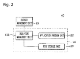
- Fig. 2 is a block diagram of a data processing apparatus of an EMS according to an embodiment
- Fig. 3 is an exemplary diagram for explaining a group of data alarm limits according to an embodiment.
- the operation and management unit 41 of the data processing apparatus 40 may include a real-time management unit 411, an application program unit 412, and a file storage unit 413.
- the real-time management unit 411 may perform check and alarm processing on collected data based on an alarm limit setting state and information according to an embodiment.
- the application program unit 412 may store various programs for providing data collection and alarm processing state information according to an embodiment.
- the application program unit 412 may store various processing programs for processing various pieces of data such as image, text or audio data or for performing following processing.
- the file storage unit 413 may store condition information for alarm processing on collected data according to an embodiment. It is possible for the file storage unit 413 to store alarm processing condition information by setting an alarm condition based on a environment and time state and receiving corresponding detailed information. Also, the file storage unit 413 may create and store a group of alarm conditions that includes a plurality of alarm conditions.
- the alarm condition information stored in the file storage unit 413 may include groups having dependency as shown in Fig. 3 .
- the data alarm condition stored in the file storage unit 413 may be obtained by storing alarm information on collected data in a tabular form as shown in Fig. 3a . It is possible to include information on the upper and lower values of an alarm limit of collected data, and information on the type of an alarm (caution, warning, and danger) and an initial data setting.
- Alarm information (in Fig. 3a ) may be obtained by storing limit information including various environments and time condition information for outputting an alarm in a table (in Fig. 3b ) form according to an embodiment.
- a limit information table (in Fig.3b ) may include at least one limit set 310.
- the limit information table (in Fig. 3b ) may be created in plurality, the table having each ID. It is possible to process an alarm on collected data by a combination of sets of various limits included in the limit information table (in Fig. 13b).
- the limit information table may include a limit set including at least one of e.g., weather, time and point conditions, have corresponding identifier information (ID) and determine an alarm condition on the collected data by using the identifier information.
- ID identifier information
- the identifier information may be set in the form that it is possible to recognize the type and state of a limit set included in the limit information table.
- the limit information table (in Fig. 13b) may include update time information on the limit set included. Also, the limit information table may store condition information (the upper limit or lower limit of an alarm output condition data value) for alarm processing on collected data when the limit set is not included.
- At least one limit set included in the limit information table may include information on an upper limit and a lower limit for each alarm output, and a limit set included in a piece of identifier information may determine whether to output data alarm, by one or more of "and" and "or” conditions.
- the limit set may include reference information on the upper and lower limits of data collected on a corresponding date based on date information in collected data and include a day limit set (in Fig. 3c ) enabling an alarm for data beyond a reference information range.
- a plural limit set and include a plural limit set (in Fig. 3e ) enabling an alarm when data matching all or any one of conditions on the plural limit set is sensed.
- a limit information table including at least one limit set with respect to collected data and determine whether to perform alarm processing on collected data based on the limit information table.
- Fig. 4 is a flowchart of a data processing operation according to an embodiment.
- the data processing apparatus 40 may receive at least one alarm limit set for outputting an alarm for collected data to set a group of alarm limits in step S402.
- the group of alarm limits may include a single limit set or a plural limit set. Also, when the limit set is not included, it is possible to set default limit information (information on one or more of the upper and lower values of a limit) on collected data.
- the data processing apparatus 40 may store a setting state on a set alarm limit set into the file storage unit 413 in step S404.
- the data processing apparatus 40 may collect data in a state in which the alarm limit set is set in step S406.
- the data processing apparatus 40 may continuously determine whether a preset limit setting state is changed during data collection. When it is sensed that the limit setting state has been changed, the data processing apparatus 40 may create a limit setting state change event and update a limit setting state on collected data based on a created event.
- the data processing apparatus 40 may read a limit condition set for a limit set to be applied to collected data, in step S412.
- the data processing apparatus 40 may determine, on collected data, whether there is data matching an alarm limit condition in step S414, and output an alarm for corresponding data when there is the data matching the alarm condition ins step S416.
- the information on whether the alarm has been output and the limit setting state has been changed may be stored into the history management unit 43.
- Embodiments may consider various environment and time conditions collecting data according to an apparatus for data processing in an EMS and process a corresponding variable data alarm to enable efficient data management and provide a reliable data alarm to a user.
Landscapes
- Engineering & Computer Science (AREA)
- Physics & Mathematics (AREA)
- General Physics & Mathematics (AREA)
- Business, Economics & Management (AREA)
- Health & Medical Sciences (AREA)
- Economics (AREA)
- Automation & Control Theory (AREA)
- Power Engineering (AREA)
- Electromagnetism (AREA)
- Radar, Positioning & Navigation (AREA)
- General Health & Medical Sciences (AREA)
- Tourism & Hospitality (AREA)
- Public Health (AREA)
- Human Resources & Organizations (AREA)
- Marketing (AREA)
- Primary Health Care (AREA)
- Strategic Management (AREA)
- Water Supply & Treatment (AREA)
- General Business, Economics & Management (AREA)
- Theoretical Computer Science (AREA)
- General Engineering & Computer Science (AREA)
- Remote Monitoring And Control Of Power-Distribution Networks (AREA)
- Testing And Monitoring For Control Systems (AREA)
- Alarm Systems (AREA)
Abstract
Description
- The present disclosure relates to a data processing apparatus of an energy management system.
- A typical energy management system may perform management and monitoring on the state of energy by material collection or material link to a broad power system. An alarm typically provided to be utilized for monitoring the operation state of a power system is an operation for recognizing a change in the operation state when there is simply the change. The alarm for event occurrence corresponding to such a simple condition undiscriminatingly generates an alarm signal even for a change in operation state occurring continuously/repetitively or by a control signal from a user. Also, an alarm server processing the alarm event may include alarm event data received from a data processing apparatus in a queue, perform an operation corresponding to an alarm type and output corresponding alarm data. That is, the alarm server searches for a data alarm condition limited to a preset state and raises the alarm when there is matching data. In this case, alarm processing on a data change matching a change in various environment conditions or a change in time condition is difficult.
- That is, by generating alarm data corresponding to a unilateral alarm condition that does not cope with various changes in data collection and alarm, it is possible to output an undiscriminating or slow alarm that does not match an alarm condition to be recognized by a user.
- Embodiments provide a data processing apparatus that may store an alarm condition matching environment and time condition information with respect to data collected from an energy management system and provide corresponding variable data state information.
- In one embodiment, a data processing apparatus includes an operation and management unit configured to collect data obtained by measuring a target, storing a limit information table, the limit information table including at least one limit set that determines whether to output an alarm for collected data, and outputting the alarm for the collected data based on the limit information table; and a history management unit configured to store history information on the operation and management unit.
- The details of one or more embodiments are set forth in the accompanying drawings and the description below. Other features will be apparent from the description and drawings, and from the claims.
-
-
Fig. 1 is a block diagram of an energy management system (EMS) according to an embodiment. -
Fig. 2 is a block diagram of a data processing apparatus of an EMS according to an embodiment. -
Fig. 3 is an exemplary diagram for explaining a group of data alarm limits according to an embodiment. -
Fig. 4 is a flowchart of a data processing operation according to an embodiment. - An energy management system (EMS) according to an embodiment includes an operation and management unit collecting data obtained by measuring a target, storing a limit information table including at least one limit set determining whether to output an alarm for collected data, and outputting the alarm for the collected data based on the limit information table; and a history management unit storing history information on the operation and management unit.
- In an EMS according to another embodiment, the operation and management unit includes a real-time management unit collecting collected data, checking whether the limit set included in a preset limit information table is changed, checking whether there is data matching the limit set and outputting an alarm for corresponding data.
- In an EMS according to still another embodiment, the operation and management unit further includes a file storage unit storing information on at least one limit set determining whether to output the alarm for the collected data.
- In an EMS according to still another embodiment, the file storage unit stores a plural limit set including information on a plural limit set.
- In an EMS according to still another embodiment, the limit information table is created in plurality according to whether the limit set is included.
- In an EMS according to still another embodiment, the limit information table includes identifier information on each limit set.
- In an EMS according to still another embodiment, the limit set included in the limit information table includes an upper or lower value of data.
- In an EMS according to still another embodiment, the operation management unit outputs an alarm when there is a value beyond a range between the upper and lower values of the data.
- In an EMS according to still another embodiment, the limit set included in the limit information table includes a type of alarm for data.
- In an EMS according to still another embodiment, the limit set included in the limit information table includes an initial setting of data.
- In an EMS according to still another embodiment, the operation and management unit stores, in the file storage unit, update information on at least one limit set included in the limit information table.
- In an EMS according to still another embodiment, the operation and management unit checks changed limit set information at every update period for the limit set and raises an alarm for a change event when it is sensed that the limit set information is changed.
- In an EMS according to still another embodiment, the operation and management unit checks changed limit set information at every update period for the limit set and reads a limit condition set for the limit set when it is not sensed that the limit set information is changed.
- Embodiments are described below in detail with reference to the accompanying drawings.
-
Fig. 1 is a block diagram of an energy management system (EMS) according to an embodiment. - Referring to
Fig. 1 , an EMS 100 according to an embodiment may include atarget 10, ameasurement system 20, acollection control system 30, adata processing apparatus 40, and a monitoring andmanagement system 50. - The
target 10 may include a power station producing electricity, a power transmission/distribution system that transmits produced electricity to a customer, and a customer load system. - The
measurement system 20 may transmit, measurement information such as a current or voltage or a modem signal such as a remote terminal unit (RTU) in a power system, to thecollection control system 30 that is located in a short distance or long distance, through an analog, digital or pulse sensor in a power generation or system process. - The
collection control system 30 may collect various pieces of field information, collect various signals transmitted from the field, convert collected signals into engineering information to convert the information into actual values, and control the information to calculate new field transmission information. The data may be transmitted to thedata processing apparatus 40 through a network. - The
data processing apparatus 40 manages various pieces of data or information according to usage. Thedata processing apparatus 40 may include an operation andmanagement unit 41 and ahistory management unit 43. A management program operating the configuration, a field-dedicated application program, a default program for monitoring may operate. In particular, thedata processing apparatus 40 according to an embodiment may perform alarm processing on data transmitted from thecollection control system 30. The alarm processing may be performed according to whether conditions on a plural limit set including an alarm limit and on a plurality of sets are matched. - The operation and
management unit 41 may store information on a plurality of conditions for alarm processing on collected data and determine based on the information on the conditions whether to output an alarm for data. - The
history management unit 43 may store information on a data processing history and alarm output history processed by the operation andmanagement unit 41 with respect to collected data. Also, it is possible for thehistory management unit 43 to store whether to change limit information for an alarm output according to an embodiment, and information on an event notification according to the change. - The monitoring and
management system 50 may include various function units that may monitor or control information. The monitoring andmanagement system 50 transmits a control command input by an operator to thetarget 10 through thedata processing apparatus 40 and thecollection control system 30 to operate a pre-determined measurement and control device. -
Fig. 2 is a block diagram of a data processing apparatus of an EMS according to an embodiment, andFig. 3 is an exemplary diagram for explaining a group of data alarm limits according to an embodiment. - Referring to
Figs. 2 and3 , the operation andmanagement unit 41 of thedata processing apparatus 40 according to an embodiment may include a real-time management unit 411, anapplication program unit 412, and afile storage unit 413. - The real-
time management unit 411 may perform check and alarm processing on collected data based on an alarm limit setting state and information according to an embodiment. - The
application program unit 412 may store various programs for providing data collection and alarm processing state information according to an embodiment. Theapplication program unit 412 may store various processing programs for processing various pieces of data such as image, text or audio data or for performing following processing. - The
file storage unit 413 may store condition information for alarm processing on collected data according to an embodiment. It is possible for thefile storage unit 413 to store alarm processing condition information by setting an alarm condition based on a environment and time state and receiving corresponding detailed information. Also, thefile storage unit 413 may create and store a group of alarm conditions that includes a plurality of alarm conditions. - The alarm condition information stored in the
file storage unit 413 may include groups having dependency as shown inFig. 3 . - The data alarm condition stored in the
file storage unit 413 may be obtained by storing alarm information on collected data in a tabular form as shown inFig. 3a . It is possible to include information on the upper and lower values of an alarm limit of collected data, and information on the type of an alarm (caution, warning, and danger) and an initial data setting. Alarm information (inFig. 3a ) may be obtained by storing limit information including various environments and time condition information for outputting an alarm in a table (inFig. 3b ) form according to an embodiment. - A limit information table (in
Fig.3b ) may include at least one limit set 310. - The limit information table (in
Fig. 3b ) may be created in plurality, the table having each ID. It is possible to process an alarm on collected data by a combination of sets of various limits included in the limit information table (in Fig. 13b). - The limit information table (in Fig. 13b) may include a limit set including at least one of e.g., weather, time and point conditions, have corresponding identifier information (ID) and determine an alarm condition on the collected data by using the identifier information. The identifier information may be set in the form that it is possible to recognize the type and state of a limit set included in the limit information table.
- The limit information table (in Fig. 13b) may include update time information on the limit set included. Also, the limit information table may store condition information (the upper limit or lower limit of an alarm output condition data value) for alarm processing on collected data when the limit set is not included.
- At least one limit set included in the limit information table may include information on an upper limit and a lower limit for each alarm output, and a limit set included in a piece of identifier information may determine whether to output data alarm, by one or more of "and" and "or" conditions.
- The limit set according to an embodiment may include reference information on the upper and lower limits of data collected on a corresponding date based on date information in collected data and include a day limit set (in
Fig. 3c ) enabling an alarm for data beyond a reference information range. - Alternatively, it is possible to include, based on collected time information, reference information on the upper and lower limits of data collected at a corresponding time and include a time limit set (in
Fig. 3d ) enabling an alarm for data beyond the reference information range. - Alternatively, it is possible to include a plural limit set and include a plural limit set (in
Fig. 3e ) enabling an alarm when data matching all or any one of conditions on the plural limit set is sensed. - Alternatively, it is possible to include, based on a specific point, reference information on the upper and lower limits of data collected at a corresponding point, and include a point limit set (in
Fig. 3f ) enabling an alarm for data beyond a reference information range. - In an embodiment as described above, it is possible to create a limit information table including at least one limit set with respect to collected data and determine whether to perform alarm processing on collected data based on the limit information table.
- A data processing operation according to an embodiment is described below in detail with reference to
Fig. 4 . -
Fig. 4 is a flowchart of a data processing operation according to an embodiment. - Referring to
Fig. 4 , thedata processing apparatus 40 according to an embodiment may receive at least one alarm limit set for outputting an alarm for collected data to set a group of alarm limits in step S402. The group of alarm limits may include a single limit set or a plural limit set. Also, when the limit set is not included, it is possible to set default limit information (information on one or more of the upper and lower values of a limit) on collected data. - The
data processing apparatus 40 may store a setting state on a set alarm limit set into thefile storage unit 413 in step S404. - The
data processing apparatus 40 may collect data in a state in which the alarm limit set is set in step S406. - The
data processing apparatus 40 may continuously determine whether a preset limit setting state is changed during data collection. When it is sensed that the limit setting state has been changed, thedata processing apparatus 40 may create a limit setting state change event and update a limit setting state on collected data based on a created event. - On the contrary, when it is not sensed that the limit setting state has been changed during data collection, the
data processing apparatus 40 may read a limit condition set for a limit set to be applied to collected data, in step S412. - The
data processing apparatus 40 may determine, on collected data, whether there is data matching an alarm limit condition in step S414, and output an alarm for corresponding data when there is the data matching the alarm condition ins step S416. The information on whether the alarm has been output and the limit setting state has been changed may be stored into thehistory management unit 43. - Embodiments may consider various environment and time conditions collecting data according to an apparatus for data processing in an EMS and process a corresponding variable data alarm to enable efficient data management and provide a reliable data alarm to a user.
Claims (13)
- A data processing apparatus 40 comprising:an operation and management unit 41 configured to collect data obtained by measuring a target 10, storing a limit information table, the limit information table comprising at least one limit set 310 that determines whether to output an alarm for collected data, and outputting the alarm for the collected data based on the limit information table; anda history management unit 43 configured to store history information on the operation and management unit 41.
- The data processing apparatus 40 according to claim 1, wherein the operation and management unit 41 comprises a real-time management unit 411 configured to collect collected data, checking whether the limit set 310 comprised in a preset limit information table is changed, checking whether there is data that matches the limit set 310 and outputting an alarm for corresponding data.
- The data processing apparatus 40 according to claim 2, wherein the operation and management unit 41 further comprises a file storage unit 413 configured to store information on at least one limit set that determines whether to output the alarm for the collected data.
- The data processing apparatus 40 according to claim 3, wherein the file storage unit 413 stores a plural limit set 310 comprising information on a plural limit set.
- The data processing apparatus 40 according to claim 3, wherein the limit information table is created in plurality according to whether the limit set 310is comprised.
- The data processing apparatus 40 according to claim 5, wherein the limit information table comprises identifier information on each limit set 310.
- The data processing apparatus 40 according to claim 1, wherein the limit set 310 comprised in the limit information table comprises an upper or lower value of data.
- The data processing apparatus 40 according to claim 7, wherein the operation management unit 41 outputs an alarm when there is a value beyond a range between the upper and lower values of the data.
- The data processing apparatus 40 according to claim 1, wherein the limit set 310 comprised in the limit information table comprises a type of alarm for data.
- The data processing apparatus 40 according to claim 1, wherein the limit set 310 comprised in the limit information table comprises an initial setting of data.
- The data processing apparatus 40 according to claim 1, wherein the operation and management unit 41 stores, into the file storage unit 413, update information on at least one limit set 310 comprised in the limit information table.
- The data processing apparatus 40 according to claim 1, wherein the operation and management unit 41 checks changed limit set information at every update period for the limit set 310 and raises an alarm for a change event when it is sensed that the limit set information is changed.
- The data processing apparatus 40 according to claim 1, wherein the operation and management unit 41 checks changed limit set information at every update period for the limit set 310 and reads a limit condition set for the limit set 310 when it is not sensed that the limit set information is changed.
Applications Claiming Priority (1)
| Application Number | Priority Date | Filing Date | Title |
|---|---|---|---|
| KR1020140032703A KR101587341B1 (en) | 2014-03-20 | 2014-03-20 | Apparatus for data processing of Energy Management System |
Publications (1)
| Publication Number | Publication Date |
|---|---|
| EP2922016A1 true EP2922016A1 (en) | 2015-09-23 |
Family
ID=52784916
Family Applications (1)
| Application Number | Title | Priority Date | Filing Date |
|---|---|---|---|
| EP15159540.2A Ceased EP2922016A1 (en) | 2014-03-20 | 2015-03-18 | Data processing apparatus of energy management system |
Country Status (4)
| Country | Link |
|---|---|
| US (1) | US9836072B2 (en) |
| EP (1) | EP2922016A1 (en) |
| KR (1) | KR101587341B1 (en) |
| CN (1) | CN104933506B (en) |
Families Citing this family (2)
| Publication number | Priority date | Publication date | Assignee | Title |
|---|---|---|---|---|
| KR20170105208A (en) * | 2016-03-09 | 2017-09-19 | 엘에스산전 주식회사 | Apparatys for data processing |
| KR102263390B1 (en) * | 2019-10-07 | 2021-06-10 | 한전케이디엔주식회사 | Apparatus and method for processing alarm message of electric power system |
Citations (3)
| Publication number | Priority date | Publication date | Assignee | Title |
|---|---|---|---|---|
| US6178362B1 (en) * | 1998-09-24 | 2001-01-23 | Silicon Energy Corp. | Energy management system and method |
| US20070038394A1 (en) * | 2004-04-01 | 2007-02-15 | Stephan Gagnon | System and method for reading power meters |
| US20090076749A1 (en) * | 2007-05-16 | 2009-03-19 | Edsa Micro Corporation | Electrical power system modeling, design, analysis, and reporting via a client-server application framework |
Family Cites Families (11)
| Publication number | Priority date | Publication date | Assignee | Title |
|---|---|---|---|---|
| JP2002358118A (en) | 2001-05-31 | 2002-12-13 | Toshiba Corp | Supervisory control system and method, and program therefor |
| US9557723B2 (en) * | 2006-07-19 | 2017-01-31 | Power Analytics Corporation | Real-time predictive systems for intelligent energy monitoring and management of electrical power networks |
| KR100934866B1 (en) * | 2007-11-06 | 2009-12-31 | 엘에스산전 주식회사 | Surveillance data collection and operation system of power system and method |
| JP2010110040A (en) | 2008-10-28 | 2010-05-13 | Toshiba Corp | Power system monitor and control equipment |
| US9286582B2 (en) * | 2009-06-22 | 2016-03-15 | Johnson Controls Technology Company | Systems and methods for detecting changes in energy usage in a building |
| US8788097B2 (en) * | 2009-06-22 | 2014-07-22 | Johnson Controls Technology Company | Systems and methods for using rule-based fault detection in a building management system |
| US8600556B2 (en) * | 2009-06-22 | 2013-12-03 | Johnson Controls Technology Company | Smart building manager |
| JP5677823B2 (en) | 2010-12-08 | 2015-02-25 | 京セラ株式会社 | Monitoring device and monitoring method |
| KR101214765B1 (en) | 2011-05-31 | 2013-01-21 | (주)정우전력 | System and method for monitoring electrical power equipment |
| JP4962813B1 (en) * | 2012-01-23 | 2012-06-27 | 日本テクノ株式会社 | Alarm output device and alarm output method |
| KR20130099507A (en) | 2012-02-29 | 2013-09-06 | (주)파서블에너지 | Apparatus and program for diagonosis of power facility |
-
2014
- 2014-03-20 KR KR1020140032703A patent/KR101587341B1/en active Active
-
2015
- 2015-03-10 US US14/643,946 patent/US9836072B2/en active Active
- 2015-03-18 EP EP15159540.2A patent/EP2922016A1/en not_active Ceased
- 2015-03-18 CN CN201510195288.7A patent/CN104933506B/en active Active
Patent Citations (3)
| Publication number | Priority date | Publication date | Assignee | Title |
|---|---|---|---|---|
| US6178362B1 (en) * | 1998-09-24 | 2001-01-23 | Silicon Energy Corp. | Energy management system and method |
| US20070038394A1 (en) * | 2004-04-01 | 2007-02-15 | Stephan Gagnon | System and method for reading power meters |
| US20090076749A1 (en) * | 2007-05-16 | 2009-03-19 | Edsa Micro Corporation | Electrical power system modeling, design, analysis, and reporting via a client-server application framework |
Also Published As
| Publication number | Publication date |
|---|---|
| US9836072B2 (en) | 2017-12-05 |
| CN104933506A (en) | 2015-09-23 |
| KR101587341B1 (en) | 2016-02-03 |
| CN104933506B (en) | 2018-09-04 |
| KR20150110863A (en) | 2015-10-05 |
| US20150268685A1 (en) | 2015-09-24 |
Similar Documents
| Publication | Publication Date | Title |
|---|---|---|
| CN104935076B (en) | Data processing device for energy management system | |
| CN102498629B (en) | Monitoring of an electrical energy supply network | |
| EP4657194A3 (en) | Methods and systems for detection in an industrial internet of things data collection environment with large data sets | |
| CN105549556B (en) | A kind of data collection and transfering system and method for industrial process real time monitoring | |
| CN104483562B (en) | Power equipment method for early warning and device | |
| JPWO2016199210A1 (en) | Data collection system and method, measurement data amount reduction method | |
| EP2632007B1 (en) | Apparatus and method for correcting error of acquired data | |
| JP2016161302A (en) | Accident point locating device and method, power system monitoring system, facility planning support system | |
| US8981895B2 (en) | Method and system for intrusion detection in networked control systems | |
| US9836072B2 (en) | Data processing apparatus of energy management system | |
| CN110411554B (en) | A method, device and system for detecting electrical equipment | |
| KR20160072412A (en) | Energy saving system using energy consumption pattern | |
| US20220206482A1 (en) | Substation equipment monitoring using a scada system | |
| CN103560920A (en) | Fault warning method and device in electric power communication network | |
| US20110161023A1 (en) | System and method for measuring machine energy consumption and productivity | |
| KR102046326B1 (en) | Apparatus for processing of data | |
| CN105608867A (en) | Information acquiring and monitoring method based on Beidou satellite | |
| JP2015136254A (en) | Power supply device and device discrimination method | |
| JP6116428B2 (en) | Power system monitoring and control apparatus and control method thereof | |
| CN105353233B (en) | A kind of transformer on-line operation ability detection method and device | |
| CN107180390B (en) | equipment for data processing | |
| KR20170035696A (en) | Apparatus for supervisory of power system | |
| CN105468058A (en) | Environment monitoring device | |
| CN117978837B (en) | Electric power data acquisition and transmission method and system thereof | |
| JP2015130131A (en) | Data creation apparatus and method |
Legal Events
| Date | Code | Title | Description |
|---|---|---|---|
| PUAI | Public reference made under article 153(3) epc to a published international application that has entered the european phase |
Free format text: ORIGINAL CODE: 0009012 |
|
| AK | Designated contracting states |
Kind code of ref document: A1 Designated state(s): AL AT BE BG CH CY CZ DE DK EE ES FI FR GB GR HR HU IE IS IT LI LT LU LV MC MK MT NL NO PL PT RO RS SE SI SK SM TR |
|
| AX | Request for extension of the european patent |
Extension state: BA ME |
|
| 17P | Request for examination filed |
Effective date: 20160323 |
|
| RBV | Designated contracting states (corrected) |
Designated state(s): AL AT BE BG CH CY CZ DE DK EE ES FI FR GB GR HR HU IE IS IT LI LT LU LV MC MK MT NL NO PL PT RO RS SE SI SK SM TR |
|
| 17Q | First examination report despatched |
Effective date: 20180823 |
|
| STAA | Information on the status of an ep patent application or granted ep patent |
Free format text: STATUS: THE APPLICATION HAS BEEN REFUSED |
|
| 18R | Application refused |
Effective date: 20200613 |