EP2921931A1 - Module-type data center and control method thereof - Google Patents
Module-type data center and control method thereof Download PDFInfo
- Publication number
- EP2921931A1 EP2921931A1 EP12888537.3A EP12888537A EP2921931A1 EP 2921931 A1 EP2921931 A1 EP 2921931A1 EP 12888537 A EP12888537 A EP 12888537A EP 2921931 A1 EP2921931 A1 EP 2921931A1
- Authority
- EP
- European Patent Office
- Prior art keywords
- opening
- closing portion
- temperature
- assumed
- fan
- Prior art date
- Legal status (The legal status is an assumption and is not a legal conclusion. Google has not performed a legal analysis and makes no representation as to the accuracy of the status listed.)
- Withdrawn
Links
Images



Classifications
-
- H—ELECTRICITY
- H05—ELECTRIC TECHNIQUES NOT OTHERWISE PROVIDED FOR
- H05K—PRINTED CIRCUITS; CASINGS OR CONSTRUCTIONAL DETAILS OF ELECTRIC APPARATUS; MANUFACTURE OF ASSEMBLAGES OF ELECTRICAL COMPONENTS
- H05K7/00—Constructional details common to different types of electric apparatus
- H05K7/20—Modifications to facilitate cooling, ventilating, or heating
- H05K7/20709—Modifications to facilitate cooling, ventilating, or heating for server racks or cabinets; for data centers, e.g. 19-inch computer racks
- H05K7/20754—Air circulating in closed loop within cabinets
-
- G—PHYSICS
- G06—COMPUTING OR CALCULATING; COUNTING
- G06F—ELECTRIC DIGITAL DATA PROCESSING
- G06F1/00—Details not covered by groups G06F3/00 - G06F13/00 and G06F21/00
- G06F1/16—Constructional details or arrangements
- G06F1/20—Cooling means
- G06F1/206—Cooling means comprising thermal management
-
- G—PHYSICS
- G05—CONTROLLING; REGULATING
- G05B—CONTROL OR REGULATING SYSTEMS IN GENERAL; FUNCTIONAL ELEMENTS OF SUCH SYSTEMS; MONITORING OR TESTING ARRANGEMENTS FOR SUCH SYSTEMS OR ELEMENTS
- G05B15/00—Systems controlled by a computer
- G05B15/02—Systems controlled by a computer electric
-
- G—PHYSICS
- G06—COMPUTING OR CALCULATING; COUNTING
- G06F—ELECTRIC DIGITAL DATA PROCESSING
- G06F1/00—Details not covered by groups G06F3/00 - G06F13/00 and G06F21/00
- G06F1/26—Power supply means, e.g. regulation thereof
- G06F1/32—Means for saving power
- G06F1/3203—Power management, i.e. event-based initiation of a power-saving mode
- G06F1/3234—Power saving characterised by the action undertaken
- G06F1/325—Power saving in peripheral device
-
- G—PHYSICS
- G06—COMPUTING OR CALCULATING; COUNTING
- G06F—ELECTRIC DIGITAL DATA PROCESSING
- G06F1/00—Details not covered by groups G06F3/00 - G06F13/00 and G06F21/00
- G06F1/26—Power supply means, e.g. regulation thereof
- G06F1/32—Means for saving power
- G06F1/3203—Power management, i.e. event-based initiation of a power-saving mode
- G06F1/3234—Power saving characterised by the action undertaken
- G06F1/3296—Power saving characterised by the action undertaken by lowering the supply or operating voltage
-
- H—ELECTRICITY
- H05—ELECTRIC TECHNIQUES NOT OTHERWISE PROVIDED FOR
- H05K—PRINTED CIRCUITS; CASINGS OR CONSTRUCTIONAL DETAILS OF ELECTRIC APPARATUS; MANUFACTURE OF ASSEMBLAGES OF ELECTRICAL COMPONENTS
- H05K7/00—Constructional details common to different types of electric apparatus
- H05K7/14—Mounting supporting structure in casing or on frame or rack
- H05K7/1485—Servers; Data center rooms, e.g. 19-inch computer racks
- H05K7/1497—Rooms for data centers; Shipping containers therefor
-
- H—ELECTRICITY
- H05—ELECTRIC TECHNIQUES NOT OTHERWISE PROVIDED FOR
- H05K—PRINTED CIRCUITS; CASINGS OR CONSTRUCTIONAL DETAILS OF ELECTRIC APPARATUS; MANUFACTURE OF ASSEMBLAGES OF ELECTRICAL COMPONENTS
- H05K7/00—Constructional details common to different types of electric apparatus
- H05K7/20—Modifications to facilitate cooling, ventilating, or heating
- H05K7/20536—Modifications to facilitate cooling, ventilating, or heating for racks or cabinets of standardised dimensions, e.g. electronic racks for aircraft or telecommunication equipment
- H05K7/207—Thermal management, e.g. cabinet temperature control
-
- H—ELECTRICITY
- H05—ELECTRIC TECHNIQUES NOT OTHERWISE PROVIDED FOR
- H05K—PRINTED CIRCUITS; CASINGS OR CONSTRUCTIONAL DETAILS OF ELECTRIC APPARATUS; MANUFACTURE OF ASSEMBLAGES OF ELECTRICAL COMPONENTS
- H05K7/00—Constructional details common to different types of electric apparatus
- H05K7/20—Modifications to facilitate cooling, ventilating, or heating
- H05K7/20709—Modifications to facilitate cooling, ventilating, or heating for server racks or cabinets; for data centers, e.g. 19-inch computer racks
- H05K7/20718—Forced ventilation of a gaseous coolant
- H05K7/20736—Forced ventilation of a gaseous coolant within cabinets for removing heat from server blades
-
- H—ELECTRICITY
- H05—ELECTRIC TECHNIQUES NOT OTHERWISE PROVIDED FOR
- H05K—PRINTED CIRCUITS; CASINGS OR CONSTRUCTIONAL DETAILS OF ELECTRIC APPARATUS; MANUFACTURE OF ASSEMBLAGES OF ELECTRICAL COMPONENTS
- H05K7/00—Constructional details common to different types of electric apparatus
- H05K7/20—Modifications to facilitate cooling, ventilating, or heating
- H05K7/20709—Modifications to facilitate cooling, ventilating, or heating for server racks or cabinets; for data centers, e.g. 19-inch computer racks
- H05K7/20718—Forced ventilation of a gaseous coolant
- H05K7/20745—Forced ventilation of a gaseous coolant within rooms for removing heat from cabinets, e.g. by air conditioning device
-
- H—ELECTRICITY
- H05—ELECTRIC TECHNIQUES NOT OTHERWISE PROVIDED FOR
- H05K—PRINTED CIRCUITS; CASINGS OR CONSTRUCTIONAL DETAILS OF ELECTRIC APPARATUS; MANUFACTURE OF ASSEMBLAGES OF ELECTRICAL COMPONENTS
- H05K7/00—Constructional details common to different types of electric apparatus
- H05K7/20—Modifications to facilitate cooling, ventilating, or heating
- H05K7/20709—Modifications to facilitate cooling, ventilating, or heating for server racks or cabinets; for data centers, e.g. 19-inch computer racks
- H05K7/20836—Thermal management, e.g. server temperature control
-
- Y—GENERAL TAGGING OF NEW TECHNOLOGICAL DEVELOPMENTS; GENERAL TAGGING OF CROSS-SECTIONAL TECHNOLOGIES SPANNING OVER SEVERAL SECTIONS OF THE IPC; TECHNICAL SUBJECTS COVERED BY FORMER USPC CROSS-REFERENCE ART COLLECTIONS [XRACs] AND DIGESTS
- Y02—TECHNOLOGIES OR APPLICATIONS FOR MITIGATION OR ADAPTATION AGAINST CLIMATE CHANGE
- Y02D—CLIMATE CHANGE MITIGATION TECHNOLOGIES IN INFORMATION AND COMMUNICATION TECHNOLOGIES [ICT], I.E. INFORMATION AND COMMUNICATION TECHNOLOGIES AIMING AT THE REDUCTION OF THEIR OWN ENERGY USE
- Y02D10/00—Energy efficient computing, e.g. low power processors, power management or thermal management
-
- Y—GENERAL TAGGING OF NEW TECHNOLOGICAL DEVELOPMENTS; GENERAL TAGGING OF CROSS-SECTIONAL TECHNOLOGIES SPANNING OVER SEVERAL SECTIONS OF THE IPC; TECHNICAL SUBJECTS COVERED BY FORMER USPC CROSS-REFERENCE ART COLLECTIONS [XRACs] AND DIGESTS
- Y02—TECHNOLOGIES OR APPLICATIONS FOR MITIGATION OR ADAPTATION AGAINST CLIMATE CHANGE
- Y02D—CLIMATE CHANGE MITIGATION TECHNOLOGIES IN INFORMATION AND COMMUNICATION TECHNOLOGIES [ICT], I.E. INFORMATION AND COMMUNICATION TECHNOLOGIES AIMING AT THE REDUCTION OF THEIR OWN ENERGY USE
- Y02D30/00—Reducing energy consumption in communication networks
- Y02D30/50—Reducing energy consumption in communication networks in wire-line communication networks, e.g. low power modes or reduced link rate
Definitions
- the embodiments discussed herein are related to a modular data center and a controlling method of a modular data center.
- Electronic devices such as servers are installed in a data center.
- a method of cooling the electronic devices there is a method using outside air.
- the outside air is taken into the data center by rotating fans, and the electronic devices are cooled directly with the outside air, without the outside air being cooled by using a heat exchanger and the like.
- this method does not require electric power for the heat exchanger and the like, and is therefore able to contribute to energy saving in the whole of the data center.
- An object of the present invention is to provide a modular data center and a controlling method a modular data center, which achieve low power consumption while preventing electronic devices from excessive cooling.
- a modular data center including an enclosure including an intake port and an exhaust port, a fan provided in the enclosure and configured to create a cooling wind by taking in outside air from the intake port, a plurality of electronic devices provided in the enclosure and configured to take in the cooling wind and to discharge an exhaust flow created from the taken cooling wind to the exhaust port, a flow passage guiding a part of the exhaust flow to upstream of the fan, an opening-closing portion configured to open and close the flow passage, and a control unit configured to adjust an air volume of the cooling wind by controlling the fan, and thereby to cool a temperature of each electronic device to a specified temperature, wherein the control unit executes closing the opening-closing portion when a first assumed value of power consumed by the fan assumed to be consumed in a case of bringing the temperature of the electronic device to the specified temperature by using the cooling wind while closing the opening-closing portion is smaller than a current value of the power, and opening the opening-closing portion when a second assumed value of the power consumed
- the cooling wind is warmed by the exhaust flow discharged from each of the electronic devices.
- the electronic devices taking in the cooling wind can be prevented from excessive cooling.
- a data center constructed by housing a fan unit and racks in a container is called a modular data center.
- Such a modular center has high cooling efficiency and therefore has an advantage in energy saving because only the space in the container needs to be cooled.
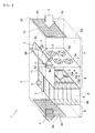
- Fig. 1 is a perspective view illustrating an internal configuration of a modular data center used for the studies by the inventors of the present application.
- This modular data center 1 includes a metallic container 2, which is an example of an enclosure.
- the container 2 has a rectangular parallelepiped shape provided with first to fourth side faces 2w, 2x, 2y, and 2z. Among these side faces, the first side face 2w and the second side face 2x have rectangular shapes which are opposed to each other. Meanwhile, an intake port 2a for taking in outside air A is provided to the third side face 2y, while an exhaust port 2b is provided to the fourth side face 2z.
- the shape of the intake port 2a is not limited to a particular shape.
- the intake port 2a may be formed from an aggregate of holes. Alternatively, a single opening may be formed as the intake port 2a. This is also the case for the intake ports 2b.
- the intake port 2a with a ventilation cover 13 such as a filter or a louver in order to avoid entry of rainwater and insects into the container 2.
- a ventilation cover 13 such as a filter or a louver in order to avoid entry of rainwater and insects into the container 2.
- the fan unit 3 is always in an operating state as long as the data center 1 is in operation.
- the fan unit 3 includes a plurality of fans 3a which create a cooling wind B from outside air A taken in from the intake port 2a.
- the fan unit 3 is not provided with a cooling mechanism such as a heat exchanger for cooling the outside air A. Accordingly, the cooling wind B is created directly from the outside air A without changing the temperature of the outside air A.
- a space between the intake port 2a and the fan unit 3 in the container 2 is served as a first room 7, into which the above-mentioned outside air A is to be taken.
- the plurality of racks 4 is arranged in a width direction of the container 2. Moreover, the racks 4 hold the electronic devices 6 such as servers, which are air cooled by the cooling wind B. Each electronic device 6 has an intake face 6a for taking in the cooling wind B. Each electronic device 6 is cooled by the cooling wind B which is taken in from the intake face 6a.
- a space between the fan unit 3 and the intake face 6a in the container 2 is served as a cold aisle 8 in which the cooling wind B flows.
- the cold aisle 8 is an example of a second room.
- the cooling wind B is taken into each electronic device 6, the cooling wind B is warmed by heat-generating components such as a CPU (central processing unit) and a GPU (graphical processing unit) included in each electronic device 6, and is then discharged as an exhaust flow E from an exhaust face 6b.
- heat-generating components such as a CPU (central processing unit) and a GPU (graphical processing unit) included in each electronic device 6, and is then discharged as an exhaust flow E from an exhaust face 6b.
- a space between the exhaust face 6b and the exhaust port 2b in the container 2 is served as a hot aisle 9 in which the warm exhaust flow E flows.
- the hot aisle 9 is an example of a third room, which shares the first side face 2w and the second side face 2x with the first room 7 and the cold aisle 8.
- a part of the exhaust flow E flowing in the hot aisle 9 bounces off the fourth side face 2z and circulates in the container 2.
- a height of each of the racks 4 is set lower than the container 2.
- a flow passage L, through which the exhaust flow E flows, is provided above the racks 4.
- the flow passage L is connected to the first room 7 and the hot aisle 9, respectively, and guides the exhaust flow E in the hot aisle 9 to upstream of the fan unit 3.
- the upstream and downstream of the fan unit 3 is defined based on the flowing direction of the cooling wind B, and the upstream corresponds to the first room 7, while the downstream corresponds to the cold aisle 8.
- a ceiling of the cold aisle 8 is defined by a plate-shaped partitioning member 11.
- the partitioning member 11 isolates the flow passage L from the cold aisle 8. Accordingly, the exhaust flow E flowing in the flow passage L does not flow into the cold aisle 8.
- an extended portion 3b formed by extending the fan unit 3 vertically upward is provided midway in the flow passage L. Outer peripheral edges of the extended portion 3b are in contact with inner surfaces of the container 2. Accordingly, the exhaust flow E does not flow into the first room 7 from the outer peripheral edges of the extended portion 3b.
- an opening 3c is formed in the extended portion 3b, and a damper serving as an opening-closing portion 5 to open and close the opening 3c is provided.
- the opening-closing portion 5 has a function to open and close the flow passage L, and has a rectangular planar shape which occludes the opening 3c. Meanwhile, the opening-closing portion 5 is provided with a shaft 5a located on a principal surface 3d of the extended portion 3b, and is rotatable about the shaft 5a by rotating an unillustrated motor. In this example, a degree ⁇ of an aperture of the opening-closing portion 5 measured from the principal surface 3d is made adjustable either continuously or stepwise in a range from 0° to 90°. Thus, it is possible to adjust a flow rate of the exhaust flow E which flows through the flow passage L.
- the angle between the principal surface 3d and the opening-closing portion 5 is defined as the degree ⁇ of the aperture in this example.
- an opening rate of the opening 3c may be employed as the degree ⁇ of the aperture.
- the data center 1 can prevent the electronic devices 6 from excessive cooling when the temperature of the outside air A is low like in winter.
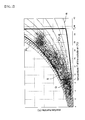
- Fig. 2 is a psychrometric chart for explaining an operation guarantee range of each electronic device.
- the psychrometric chart plots iso-relative humidity lines.
- the horizontal axis of the chart indicates a dry-bulb temperature, and the vertical axis thereof indicates an absolute humidity.
- a temperature T of the outside air A is measured as the dry-bulb temperature, while a humidity H of the outside air A is measured as a relative humidity.
- a plurality of dots in Fig. 2 represents actual measured values of the dry-bulb temperatures and the relative humidities of the outside air in Tokyo.
- a temperature range T 1 to T 2 of the dry-bulb temperature and a humidity range H 1 to H 2 of the relative humidity are set to each electronic device 6 in order to guarantee their operation.
- a region in the temperature range and the humidity range is indicated as an operation guarantee region S.
- the temperature range T 1 to T 2 is set to a range from 10°C to 35°C
- the humidity range H 1 to H 2 is set to a range from 10% to 85%, for example.
- a lower limit temperature T 1 and an upper limit temperature T 2 of the temperature range T 1 to T 2 are limit temperatures which allow normal operation of an unillustrated operating unit such as a CPU and a GPU in the electronic device 6.
- a lower limit humidity H 1 in the humidity range H 1 to H 2 is an approximate humidity at which the electronic device 6 is likely to be damaged by static electricity due to dry air
- an upper limit humidity H 2 is a humidity at which dew condensation due to highly humid air is likely to occur in the electronic device 6.
- the electronic devices 6 When a state point P, whose coordinates are the temperature T and the humidity H of the outside air A, is located within the operation guarantee range S, it is possible to air cool the electronic devices 6 by directly using the outside air A. Accordingly, in this case, the electronic devices 6 may be cooled by using only the cooling wind B while closing the opening-closing portion 5.
- the cooling wind B is warmed with the exhaust flow E by opening the opening-closing portion 5.
- a state point of a mixed air flow of the cooling wind B and the exhaust flow E is set within the operation guarantee range S, and the electronic devices 6 can be prevented from excessive cooling.
- the state point of the mixed air flow can be set within the operation guarantee range S.
- a region to open the opening-closing portion 5 as described above is hatched, and this region is indicated as an operation region Q of the opening-closing portion 5.
- the lower limit temperature T 1 located on a boundary between the operation region Q and the operation guarantee region S constitutes one of threshold temperatures to open the opening-closing portion 5.
- the opening-closing portion 5 is opened and the cooling wind B is warmed with the exhaust flow E when the temperature T of the outside air A is lower than the lower limit temperature T 1 .
- actual temperatures of the electronic devices 6 also depend on an air volume of the cooling wind B. For example, even if the temperature T of the outside air A is constant, the electronic device 6 is cooled down more efficiently when the air volume of the cooling wind B is larger. Then, when the air volume of the cooling wind B is small, the electronic device 6 is prone to be cooled insufficiency.
- amount of heat generation by the electronic device 6 may be increased when operating rate of the electronic device 6 is high. In this case, the electronic device 6 may not be sufficiently cooled unless the air volume of the cooling wind B is increased.
- the mere opening and closing operations of the opening-closing portion 5 as described above are not enough for controlling the temperature of the electronic device 6.
- the electronic device 6 needs to be cooled to a predetermined temperature by controlling the number of rotation of the fan 3a, and thereby adjusting the air volume of the cooling wind B.
- a temperature at which each electronic device 6 causes thermal runaway is preset as a specified temperature T s , and the number of rotation of the fan 3a is controlled such that the temperature of the electronic device 6 does not exceed the specified temperature T s , thereby adjusting the air volume of the cooling wind B.
- the air volume of the cooling wing B varies in accordance with a static pressure of the fan 3a.
- the static pressure is defined as a difference in pressure between the upstream side and the downstream side of the fan 3a.
- the pressure in the first room 7 from which the outside air A is taken out by the fan 3a is thought to be smaller than the pressure in the cold aisle 8 to which the cooling wind B is supplied by the fan 3a. Accordingly, when the static pressure of the fan 3a becomes high, the air volume of the cooling wind B that the fan 3a can send out is reduced as compared to that in the case where the static pressure is small. Hence, the fan 3a may not be able to create the required amount of the cooling wind B for cooling the electronic device 6 to the specified temperature T s .
- the intake port 2a is provided with the ventilation cover 13 such as the filter or the louver, the intake of the outside air A at the intake port 2a is deteriorated, and the pressure in the first room 7 is further reduced. Hence, the reduction in air volume of the cooling wind B becomes significant.
- the required amount of the cooling wind B for cooling the electronic device 6 to the specified temperature T s is increased more than that in the case of closing the opening-closing portion 5, and that the power consumption by the fan unit 3 is likely to be increased accordingly.
- the inventors of the present application investigated in which case the opening-closing portion 5 is to be opened or closed in order to reduce the power consumption by the fan unit 3.
- Fig. 3 illustrates a result of the investigation.
- Fig. 3 is a graph illustrating a relation between the power P 0 consumed by the fan unit 3 required for cooling each electronic device 6 to the specified temperature T s and the temperature T of the outside air A when the operating rate of each electronic device 6 is fixed.
- the modular data center 1 of Fig. 1 is controlled as described below, so that the power consumption of the data center 1 is reduced.
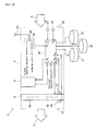
- Fig. 4 is a functional block diagram of the modular data center 1. Note that this functional block diagram schematically illustrates functional links between the functional blocks in the modular data center 1. Accordingly, there are some portions which are different from an actual layout of constituents that correspond to each function.
- the modular data center 1 is provided with a control unit 20, a temperature sensor 21, a humidity sensor 22, a power line 23, a switchboard 24, a first pressure sensor 27, and a second pressure sensor 28.
- control unit 20 a dedicated computer may be used as the control unit 20, or one of the pluralities of electronic devices 6 (see Fig. 1 ) may be used as the control unit 20.
- the control unit 20 outputs a first control signal S 1 to the fan unit 3.
- the control unit 20 adjusts the numbers of rotations of the fans 3a and controls the air volume of the cooling wind B, thereby cooling the electronic devices 6 to the specified temperature T s .
- a method of adjusting the number of rotation of the fan 3a is not particularly limited. However, it is preferable to cause the control unit 20 to monitor actual temperatures of the electronic devices 6 and to control the number of rotation of the fan 3a in real time in accordance with the actual temperatures.
- control unit 20 outputs a second control signal S 2 to the damper provided as the opening-closing portion 5, thereby controlling the degree ⁇ of the aperture of the opening-closing portion 5. Then, aperture information S ⁇ indicating the actual degree ⁇ of the aperture of the opening-closing portion 5 is outputted from the opening-closing portion 5 to the control unit 20.
- the power line 23 is used to supply electric power from outside into the data center 1.
- the power line 23 branches off to two lines at the switchboard 24 in the data center 1.
- One of the branched lines is connected to the fan unit 3, and the power consumption of all the fans 3a in the fan unit 3 is monitored by a power meter 25.
- the power meter 25 outputs the power currently consumed by the fan unit 3 as power information S f to the control unit 20.
- the other line branched off from the power line 23 is connected to the plurality of electronic devices 6.
- the temperature sensor 21 and the humidity sensor 22 are provided at positions in the vicinity of the intake port 2a and the like and exposed to the outside air A.
- the temperature sensor 21 and the humidity sensor 22 measure the temperature T and the humidity H of the outside air A, and output the measured values to the control unit 20 as temperature information S T and humidity information S H , respectively.
- the first pressure sensor 27 measures an atmospheric pressure P f at the upstream side of the fan 3a and outputs the measured value to the control unit 20 as first pressure information S Pf .
- the second pressure sensor 28 measures an atmospheric pressure P b at the downstream side of the fan 3a and outputs the measured value to the control unit 20 as second pressure information S Pb .
- operating rate information S ⁇ is inputted from each of the plurality of electronic devices 6 to the control unit 20.
- the operating rate information S ⁇ is information indicating an operating rate ⁇ 0 of each electronic device 6, which is outputted from each electronic device 6.
- the operating rate ⁇ 0 is not particularly limited, the operating rate of the processing unit such as the CPU and the GPU included in the electronic device 6 may be employed as the operating rate ⁇ 0 .
- the control unit 20 can acquire parameters T, H, ⁇ 0 , and ⁇ in real time, which respectively correspond to the above information.
- control unit 20 refers to at least one of first to third databases 31 to 33, and determines whether the opening-closing portion 5 is to be opened or closed in order to reduce the power consumed by the fan unit 3.
- the first to third databases 31 to 33 may be provided outside the modular data center 1 or may be held by the control unit 20. Note that the contents of the databases 31 to 33 will be described later.
- Fig. 5 is a flowchart illustrating the controlling method of the modular data center of this embodiment.
- the control unit 20 refers to the above-described power information S f , and thereby acquires the current value P 0 of the power consumed by the fan unit 3.
- step S2 the control unit 20 determines whether or not the opening-closing portion 5 is closed.
- This step is executed by causing the control unit 20 to obtain the degree ⁇ of the aperture of the opening-closing portion 5 on the basis of the aperture information S ⁇ , and to determine that the opening-closing portion 5 is closed when the degree ⁇ is equal to 0°, and to determine that the opening-closing portion 5 is not closed when the degree ⁇ is not equal to 0°.
- step S3 when the opening-closing portion 5 is determined to be not closed (NO).
- step S3 a first assumed value P 1 of the power consumed by the fan unit 3, which is assumed in the case of bringing the temperature of the electronic device 6 to the aforementioned specified temperature T s by using the cooling wind B while closing the opening-closing portion 5, is calculated as described below.
- the first assumed value P 1 of the power consumed by the fan unit 3 depends on the temperature T of the outside air A and the operating rate ⁇ 0 .
- an average value or a maximum value of the plurality of operating rates ⁇ 0 may be used as the representative value ⁇ .
- the function f provides the first assumed value P 1 of the power consumed by the fan unit 3 which is required for bringing the temperature of each electronic device 6 to the specified temperature T s when the values T and ⁇ are given.
- the function f is an example of the above-mentioned first database 31.
- Fig. 6 is a graph schematically illustrating the first database 31.
- Each curve in Fig. 6 represents the above-described function f in the form of a graph.
- the horizontal axis of the graph is the temperature T of the outside air A, while the vertical axis thereof is the first assumed value P 1 of the power consumed by the fan unit 3.
- Fig. 6 illustrates three graphs respectively corresponding to progressively-increasing representative values ⁇ 1 , ⁇ 2 , and ⁇ 3 .
- the graphs can be obtained by means of simulation, or by conducting experiments while actually operating the modular database 1.
- the control unit 20 can acquire the first assumed value P 1 corresponding to the current values of T and ⁇ by referring to the first database 31.
- the first database 31 is not limited to the graphs illustrated in Fig. 6 , and may be formed from a table storing the respective values T, ⁇ , and P 1 .
- step S4 when the opening-closing portion 5 is determined to be closed (YES) in step S2 of Fig. 5 .
- a second assumed value P 2 of the power consumed by the fan unit 3, which is assumed in the case of bringing the temperature of the electronic device 6 to the aforementioned specified temperature T s by using the cooling wind B while opening the opening-closing portion 5, is calculated as described below.
- the power consumed by the fan unit 3 is thought to be increased as described above since the temperature of the cooling wind B is increased by being mixed with the exhaust flow E. On the other hand, the power is also thought to be decreased since the static pressure of the fan 3a is reduced.
- the second assumed value P 2 which is corrected in consideration of the changes in temperature and static pressure as described above.
- the temperature rise T H is thought to be small when the degree ⁇ of the aperture of the opening-closing portion 5 is small and thus a flow rate of the exhaust flow E flowing through the opening-closing portion 5 is small.
- a temperature decrease T H is thought to be small depending on the temperature T of the outside air A.
- the temperature rise T H of the cooling wing B is thought to be increased.
- the form of the function h can be obtained by means of simulation, or by conducting experiments while actually operating the modular database 1.
- P' 2 f(T+h(T, ⁇ , ⁇ ), ⁇ ).
- the second assumed value P 2 to be calculated in this step can be calculated by further correcting P' 2 in consideration of the change in static pressure of the fan 3a.
- the function i may be determined by use of a static pressure - air volume characteristic of the fan 3a, or obtained by conducting experiments while actually operating the data center 1.
- Fig. 7 is a graph schematically illustrating the above-described function i.
- Each curve in Fig. 7 represents the function i in the form of a graph.
- the horizontal axis of the graph is the degree ⁇ of the aperture of the opening-closing portion 5, while the vertical axis thereof is the second assumed value P 2 of the power consumed by the fan unit 3.
- Fig. 7 illustrates three graphs respectively corresponding to progressively-increasing values P' 2a , P' 2b , and P' 2c , which are not subjected to the correction.
- the second assumed values P 2 corresponding to the parameters T, ⁇ , and ⁇ are stored in the second database 32 in advance.
- step S4 can be executed by causing the control unit 20 to refer to the second database 32 and to read the second assumed value P 2 corresponding to the current parameters T, ⁇ , and ⁇ .
- the second assumed value P 2 is corrected in consideration of the change in temperature of the cooling wind B and the change in static pressure of the fan 3a associated with the opening of the opening-closing portion 5 as described above. Accordingly, it is possible to accurately obtain the second assumed value P 2 to be expected in the future.
- the second assumed value P 2 may be calculated by causing the control unit 20 to refer to the third database 33 (see Fig. 4 ).
- the function j is a function which derives the second assumed value P 2 from the value P' 2 before the correction and a static pressure ⁇ P of the fan 3a.
- the reason for using the value P' 2 as the first variable of the function j is that the second assumed value P 2 is thought to depend on the value P' 2 before the correction as in the function i.
- the reason for using the static pressure ⁇ P as the second variable of the function j is that it is more difficult for the fan 3a to send out the cooling wind B as the static pressure ⁇ P becomes higher, and the required air volume of the cooling wind B for bringing each electronic device 6 to the specified temperature T s cannot be created unless the number of rotation of the fan 3a is increased.
- Fig. 8 is a graph schematically illustrating the above-described function j.
- Each curve in Fig. 8 represents the function j in the form of a graph.
- the horizontal axis of the graph is the static pressure ⁇ P of the fan 3a, while the vertical axis thereof is the second assumed value P 2 of the power consumed by the fan unit 3.
- Fig. 8 illustrates three graphs respectively corresponding to the progressively-increasing values P' 2a , P' 2b , and P' 2c prior to the correction as in Fig. 7 .
- the second assumed values P 2 corresponding to the parameters T, ⁇ , ⁇ , and ⁇ P are stored in the third database 33 in advance.
- step S4 can be executed by causing the control unit 20 to refer to the third database 33 and to read the second assumed value P 2 corresponding to the current parameters T, ⁇ , ⁇ , and ⁇ P.
- the static pressure ⁇ P is calculated by the control unit 20 by finding a difference (P b -P f ) between the pressures P f and P b respectively included in the first pressure information S Pf and the second pressure information S Pb .
- step S3 or step S4 is completed in this manner, the method proceeds to step S5 of Fig. 5 .
- step S5 the control unit 20 evaluates a magnitude relation between the current value P 0 and the first assumed value P 1 of the power consumed by the fan unit 3, and a magnitude relation between the current value P 0 and the second assumed value P 2 of the power.
- the first assumed value P 1 is the assumed value of the power consumed by the fan unit 3, which is assumed in the case of closing the opening-closing portion 5. Accordingly, when the first assumed value P 1 is evaluated to be smaller than the current value P 0 (P 1 ⁇ P 0 ) in this step, the power consumed by the fan unit 3 can be reduced as compared to the current situation by closing the opening-closing portion 5. Therefore, the control unit 20 closes the opening-closing portion 5 when the relation is evaluated as P 1 ⁇ P 0 .
- the second assumed value P 2 is the assumed value of the power consumed by the fan unit 3, which is assumed in the case of opening the opening-closing portion 5. Accordingly, when the second assumed value P 2 is evaluated to be smaller than the current value P 0 (P 2 ⁇ P 0 ) in this step, the power consumed by the fan unit 3 can be reduced as compared to the current situation by opening the opening-closing portion 5. Therefore, the control unit 20 opens the opening-closing portion 5 when the relation is evaluated as P 2 ⁇ P 0 .
- Fig. 9 schematically illustrates the contents of the processing in step S5.
- the first database 31 and the second database 32 are schematically illustrated in tables, respectively.
- the first database 31 is formed by relating the first assumed value P 1 of the power consumed by the fan unit 3 to the temperature T of the outside air A and the representative value ⁇ of the operating rates of the electronic devices 6.
- the second database 32 is formed by relating the second assumed value P 2 of the power consumed by the fan unit 3 to the temperature T, the degree ⁇ of the aperture, and the representative value ⁇ .
- the temperature T and the representative value ⁇ are set as the entries of the table, whereas the degree ⁇ of the aperture is omitted.
- the reason for omitting the degree ⁇ of the aperture is to formally conform the style of the table to that of the first database 31.
- the opening or closing of the opening-closing portion 5 is determined by comparing the current value P 0 of the power consumed by the fan unit 3 with the first assumed value P 1 (0.804 kW) and the second assumed value P 2 (0.864 kW).
- step S5 determination of the opening or closing of the opening-closing portion 5 in step S5 is continuously conducted by repeating the above-described control at time intervals of several seconds, so that the power consumption of the modular data center 1 is reduced.
- the opening-closing portion 5 is opened and closed in step S5 by comparing the current value P 0 of the power consumed by the fan unit 3 with the assumed values P 1 and P 2 thereof.
- the opening-closing portion 5 is opened and closed in step S5 by comparing the current value P 0 of the power consumed by the fan unit 3 with the assumed values P 1 and P 2 thereof.
- the determination to open or close the opening-closing portion 5 is made with reference to the first and second databases 31 and 32, it is not necessary to measure the power consumed by the fan unit 3 after actually opening or closing the opening-closing portion 5. Thus, the determination to open or close the opening-closing portion 5 can be made promptly.
- the electronic device 6 such as a server, in which the air volume of the cooling wind B required for cooling to the specified temperature T s varies depending on the operating rate.
- the lower limit temperature T 1 of the operation guarantee region S is employed as one of threshold temperatures used for opening the opening-closing portion 5.
- the dimensions of the container 2 used for the investigation include a depth of 3474.6 mm, a width of 2331.6 mm, and a height of 2769.7 mm.
- the opening-closing portion 5 is hypothesized to exhibit the degree ⁇ of the aperture of either 0% or 100% only.
- Fig. 10 is a graph illustrating the operation region Q when the modular data center 1 is operated in accordance with the present embodiment under the above-mentioned conditions. Note that the elements explained with reference to Fig. 2 are denoted by the same reference numerals as those in Fig. 10 and descriptions thereof will be omitted hereinbelow.
- the operation region Q to open the opening-closing portion 5 was successfully expanded to a region R by operating the modular data center 1 in accordance with the present embodiment.
- the region R is a region where it is possible to reduce the power consumed by the fan unit 3 by opening the opening-closing portion 5 as compared to the case of closing the opening-closing portion 5.
- the power consumed by the fan unit 3 could be reduced by opening the opening-closing portion 5 even when the temperature T of the outside air A was around 20°C.
- the inventors of the present application also investigated how much of the electrical energy of the fan unit 3 could be reduced in one year by operating the data center 1 in accordance with the present embodiment.
- Fig. 11 illustrates a result of this investigation.
- the opening-closing portion 5 is thought to be opened for a longer period of time than in Tokyo in order to warm the cooling wind B with the exhaust flow E.
- the annual periods for opening the opening-closing portion 5 were 2737 hours in Tokyo and 6110 hours in Anchorage.
- the periods for opening the opening-closing portion 5 were increased by 2867 hours in Tokyo and 2641 hours in Anchorage.
- the opening-closing portion 5 is opened only when it is determined that the power consumed by the fan unit 3 can be reduced more than the current situation as described previously. Accordingly, when the periods for opening the opening-closing portion 5 become longer in this manner, the reduction effects on the fan unit 3 are deemed to be improved more.
Landscapes
- Engineering & Computer Science (AREA)
- Physics & Mathematics (AREA)
- General Engineering & Computer Science (AREA)
- Theoretical Computer Science (AREA)
- Microelectronics & Electronic Packaging (AREA)
- Computer Hardware Design (AREA)
- Thermal Sciences (AREA)
- General Physics & Mathematics (AREA)
- Human Computer Interaction (AREA)
- Aviation & Aerospace Engineering (AREA)
- Automation & Control Theory (AREA)
- Cooling Or The Like Of Electrical Apparatus (AREA)
- Ventilation (AREA)
- Air-Flow Control Members (AREA)
- Air Conditioning Control Device (AREA)
Abstract
Description
- The embodiments discussed herein are related to a modular data center and a controlling method of a modular data center.
- Electronic devices such as servers are installed in a data center. As a method of cooling the electronic devices, there is a method using outside air. According to this method, the outside air is taken into the data center by rotating fans, and the electronic devices are cooled directly with the outside air, without the outside air being cooled by using a heat exchanger and the like. Thus, this method does not require electric power for the heat exchanger and the like, and is therefore able to contribute to energy saving in the whole of the data center.
- However, when the outside air is directly used in the case where the outside air temperature is low as in winter, the electronic devices may be cooled excessively and the temperatures of the electronic devices may deviate from their operation guarantee ranges. For this reason, it is desirable to warm the inside of the data center by using some mechanisms. However, in some operating conditions of the mechanisms, there is a risk of an increase in power consumption in the data center.
-
- Patent Document 1: Japanese Laid-open Patent Publication No.
02-290454 - Patent Document 2: Japanese Laid-open Patent Publication No.
08-193727 - An object of the present invention is to provide a modular data center and a controlling method a modular data center, which achieve low power consumption while preventing electronic devices from excessive cooling.
- According to an aspect discussed herein, there is provided a modular data center including an enclosure including an intake port and an exhaust port, a fan provided in the enclosure and configured to create a cooling wind by taking in outside air from the intake port, a plurality of electronic devices provided in the enclosure and configured to take in the cooling wind and to discharge an exhaust flow created from the taken cooling wind to the exhaust port, a flow passage guiding a part of the exhaust flow to upstream of the fan, an opening-closing portion configured to open and close the flow passage, and a control unit configured to adjust an air volume of the cooling wind by controlling the fan, and thereby to cool a temperature of each electronic device to a specified temperature, wherein the control unit executes closing the opening-closing portion when a first assumed value of power consumed by the fan assumed to be consumed in a case of bringing the temperature of the electronic device to the specified temperature by using the cooling wind while closing the opening-closing portion is smaller than a current value of the power, and opening the opening-closing portion when a second assumed value of the power consumed by the fan assumed to be consumed in a case of bringing the temperature of the electronic device to the specified temperature by using the cooling wind while opening the opening-closing portion is smaller than the current value of the power.
- According to the following disclosure, the cooling wind is warmed by the exhaust flow discharged from each of the electronic devices. Thus, the electronic devices taking in the cooling wind can be prevented from excessive cooling. In addition, it is possible to reduce the power consumed by the fan by quickly opening or closing the opening-closing portion while using the first assumed value and the second assumed value of the power consumed by the fan.
-
- [
Fig. 1] Fig. 1 is a perspective view illustrating an internal configuration of a modular data center. - [
Fig. 2] Fig. 2 is a psychrometric chart for explaining an operation guarantee range of an electronic device. - [
Fig. 3] Fig. 3 is a graph illustrating a relation between a temperature of outside air and electric power consumed by a fan unit required to cool eachelectronic device 6 to a specified temperature when an operating rate of the electronic device is fixed. - [
Fig. 4] Fig. 4 is a functional block diagram of a modular data center according to an embodiment. - [
Fig. 5] Fig. 5 is a flowchart illustrating a controlling method of a modular data center according to the embodiment. - [
Fig. 6] Fig. 6 is a graph schematically illustrating a first database used in the embodiment. - [
Fig. 7] Fig. 7 is a graph schematically illustrating a function i used in the embodiment. - [
Fig. 8] Fig. 8 is a graph schematically illustrating a function j used in the embodiment. - [
Fig. 9] Fig. 9 schematically illustrates the contents of the processing in step S5. - [
Fig. 10] Fig. 10 is a graph illustrating an operation region when the modular data center is operated in accordance with the embodiment. - [
Fig. 11] Fig. 11 is a graph illustrating a result of an investigation to investigate how much of the electrical energy of the fan unit of the modular data center according to the embodiment can be reduced in one year. - Prior to explaining the present embodiments, results of studies conducted by the inventors of the present application will be explained.
- While there are various types of data centers, a data center constructed by housing a fan unit and racks in a container is called a modular data center. Such a modular center has high cooling efficiency and therefore has an advantage in energy saving because only the space in the container needs to be cooled.
-
Fig. 1 is a perspective view illustrating an internal configuration of a modular data center used for the studies by the inventors of the present application. - This
modular data center 1 includes ametallic container 2, which is an example of an enclosure. Afan unit 3 and a plurality ofracks 4 opposed thereto provided in thecontainer 2. - The
container 2 has a rectangular parallelepiped shape provided with first tofourth side faces first side face 2w and thesecond side face 2x have rectangular shapes which are opposed to each other. Meanwhile, anintake port 2a for taking in outside air A is provided to thethird side face 2y, while anexhaust port 2b is provided to thefourth side face 2z. - Here, the shape of the
intake port 2a is not limited to a particular shape. Theintake port 2a may be formed from an aggregate of holes. Alternatively, a single opening may be formed as theintake port 2a. This is also the case for theintake ports 2b. - Meanwhile, it is preferable to provide the
intake port 2a with aventilation cover 13 such as a filter or a louver in order to avoid entry of rainwater and insects into thecontainer 2. - The
fan unit 3 is always in an operating state as long as thedata center 1 is in operation. Thefan unit 3 includes a plurality offans 3a which create a cooling wind B from outside air A taken in from theintake port 2a. - In order to suppress power consumption of the
fan unit 3, thefan unit 3 is not provided with a cooling mechanism such as a heat exchanger for cooling the outside air A. Accordingly, the cooling wind B is created directly from the outside air A without changing the temperature of the outside air A. - Meanwhile, a space between the
intake port 2a and thefan unit 3 in thecontainer 2 is served as afirst room 7, into which the above-mentioned outside air A is to be taken. - On the other hand, the plurality of
racks 4 is arranged in a width direction of thecontainer 2. Moreover, theracks 4 hold theelectronic devices 6 such as servers, which are air cooled by the cooling wind B. Eachelectronic device 6 has anintake face 6a for taking in the cooling wind B. Eachelectronic device 6 is cooled by the cooling wind B which is taken in from theintake face 6a. - Here, a space between the
fan unit 3 and theintake face 6a in thecontainer 2 is served as acold aisle 8 in which the cooling wind B flows. Thecold aisle 8 is an example of a second room. - After the cooling wind B is taken into each
electronic device 6, the cooling wind B is warmed by heat-generating components such as a CPU (central processing unit) and a GPU (graphical processing unit) included in eachelectronic device 6, and is then discharged as an exhaust flow E from anexhaust face 6b. - A space between the
exhaust face 6b and theexhaust port 2b in thecontainer 2 is served as ahot aisle 9 in which the warm exhaust flow E flows. Thehot aisle 9 is an example of a third room, which shares thefirst side face 2w and thesecond side face 2x with thefirst room 7 and thecold aisle 8. - Here, a part of the exhaust flow E flowing in the
hot aisle 9 bounces off thefourth side face 2z and circulates in thecontainer 2. In this example, a height of each of theracks 4 is set lower than thecontainer 2. A flow passage L, through which the exhaust flow E flows, is provided above theracks 4. - The flow passage L is connected to the
first room 7 and thehot aisle 9, respectively, and guides the exhaust flow E in thehot aisle 9 to upstream of thefan unit 3. Here, the upstream and downstream of thefan unit 3 is defined based on the flowing direction of the cooling wind B, and the upstream corresponds to thefirst room 7, while the downstream corresponds to thecold aisle 8. - Meanwhile, a ceiling of the
cold aisle 8 is defined by a plate-shaped partitioningmember 11. The partitioningmember 11 isolates the flow passage L from thecold aisle 8. Accordingly, the exhaust flow E flowing in the flow passage L does not flow into thecold aisle 8. - Moreover, an
extended portion 3b formed by extending thefan unit 3 vertically upward is provided midway in the flow passage L. Outer peripheral edges of theextended portion 3b are in contact with inner surfaces of thecontainer 2. Accordingly, the exhaust flow E does not flow into thefirst room 7 from the outer peripheral edges of theextended portion 3b. - In addition, an opening 3c is formed in the
extended portion 3b, and a damper serving as an opening-closingportion 5 to open and close the opening 3c is provided. - The opening-closing
portion 5 has a function to open and close the flow passage L, and has a rectangular planar shape which occludes theopening 3c. Meanwhile, the opening-closingportion 5 is provided with ashaft 5a located on aprincipal surface 3d of theextended portion 3b, and is rotatable about theshaft 5a by rotating an unillustrated motor. In this example, a degree θ of an aperture of the opening-closingportion 5 measured from theprincipal surface 3d is made adjustable either continuously or stepwise in a range from 0° to 90°. Thus, it is possible to adjust a flow rate of the exhaust flow E which flows through the flow passage L. - Here, the angle between the
principal surface 3d and the opening-closingportion 5 is defined as the degree θ of the aperture in this example. Alternatively, an opening rate of theopening 3c may be employed as the degree θ of the aperture. - When the exhaust flow E is guided to the upstream side of the
fan unit 3 via the opening-closingportion 5, the warm exhaust flow E and the outside air A are mixed together in thefirst room 7. Accordingly, it is possible to increase the temperature of the cooling wind B to be supplied to thecold aisle 8. - By warming the cooling wind B with the exhaust flow E in this manner, the
data center 1 can prevent theelectronic devices 6 from excessive cooling when the temperature of the outside air A is low like in winter. -
Fig. 2 is a psychrometric chart for explaining an operation guarantee range of each electronic device. The psychrometric chart plots iso-relative humidity lines. The horizontal axis of the chart indicates a dry-bulb temperature, and the vertical axis thereof indicates an absolute humidity. - In the following, a temperature T of the outside air A is measured as the dry-bulb temperature, while a humidity H of the outside air A is measured as a relative humidity. A plurality of dots in
Fig. 2 represents actual measured values of the dry-bulb temperatures and the relative humidities of the outside air in Tokyo. - A temperature range T1 to T2 of the dry-bulb temperature and a humidity range H1 to H2 of the relative humidity are set to each
electronic device 6 in order to guarantee their operation. InFig. 2 , a region in the temperature range and the humidity range is indicated as an operation guarantee region S. - In the following, the temperature range T1 to T2 is set to a range from 10°C to 35°C, and the humidity range H1 to H2 is set to a range from 10% to 85%, for example. A lower limit temperature T1 and an upper limit temperature T2 of the temperature range T1 to T2 are limit temperatures which allow normal operation of an unillustrated operating unit such as a CPU and a GPU in the
electronic device 6. Meanwhile, a lower limit humidity H1 in the humidity range H1 to H2 is an approximate humidity at which theelectronic device 6 is likely to be damaged by static electricity due to dry air, while an upper limit humidity H2 is a humidity at which dew condensation due to highly humid air is likely to occur in theelectronic device 6. - When a state point P, whose coordinates are the temperature T and the humidity H of the outside air A, is located within the operation guarantee range S, it is possible to air cool the
electronic devices 6 by directly using the outside air A. Accordingly, in this case, theelectronic devices 6 may be cooled by using only the cooling wind B while closing the opening-closingportion 5. - On the other hand, when the temperature T of the outside air A is lower than the lower limit temperature T1 of the operation guarantee range S as in winter, the cooling wind B is warmed with the exhaust flow E by opening the opening-closing
portion 5. Thus, a state point of a mixed air flow of the cooling wind B and the exhaust flow E is set within the operation guarantee range S, and theelectronic devices 6 can be prevented from excessive cooling. - Moreover, when the humidity H of the outside air A is higher than the upper limit humidity H2, a relative humidity of the mixed air flow of the exhaust flow E and the cooling wind B is reduced by opening the opening-closing
portion 5 and thereby warming the cooling wind B with the exhaust flow E. Thus, the state point of the mixed air flow can be set within the operation guarantee range S. - In
Fig. 2 , a region to open the opening-closingportion 5 as described above is hatched, and this region is indicated as an operation region Q of the opening-closingportion 5. Moreover, the lower limit temperature T1 located on a boundary between the operation region Q and the operation guarantee region S constitutes one of threshold temperatures to open the opening-closingportion 5. - Hence, the opening-closing
portion 5 is opened and the cooling wind B is warmed with the exhaust flow E when the temperature T of the outside air A is lower than the lower limit temperature T1. However, actual temperatures of theelectronic devices 6 also depend on an air volume of the cooling wind B. For example, even if the temperature T of the outside air A is constant, theelectronic device 6 is cooled down more efficiently when the air volume of the cooling wind B is larger. Then, when the air volume of the cooling wind B is small, theelectronic device 6 is prone to be cooled insufficiency. - Furthermore, amount of heat generation by the
electronic device 6 may be increased when operating rate of theelectronic device 6 is high. In this case, theelectronic device 6 may not be sufficiently cooled unless the air volume of the cooling wind B is increased. - Accordingly, the mere opening and closing operations of the opening-closing
portion 5 as described above are not enough for controlling the temperature of theelectronic device 6. Theelectronic device 6 needs to be cooled to a predetermined temperature by controlling the number of rotation of thefan 3a, and thereby adjusting the air volume of the cooling wind B. - There are no limitations as to how much the
electronic devices 6 are to be cooled. In the following, a temperature at which eachelectronic device 6 causes thermal runaway is preset as a specified temperature Ts, and the number of rotation of thefan 3a is controlled such that the temperature of theelectronic device 6 does not exceed the specified temperature Ts, thereby adjusting the air volume of the cooling wind B. - However, even when the number of the revolution of the
fan 3a is the same, the air volume of the cooling wing B varies in accordance with a static pressure of thefan 3a. The static pressure is defined as a difference in pressure between the upstream side and the downstream side of thefan 3a. - In the example of
Fig. 1 , the pressure in thefirst room 7 from which the outside air A is taken out by thefan 3a is thought to be smaller than the pressure in thecold aisle 8 to which the cooling wind B is supplied by thefan 3a. Accordingly, when the static pressure of thefan 3a becomes high, the air volume of the cooling wind B that thefan 3a can send out is reduced as compared to that in the case where the static pressure is small. Hence, thefan 3a may not be able to create the required amount of the cooling wind B for cooling theelectronic device 6 to the specified temperature Ts. - Particularly, when the
intake port 2a is provided with theventilation cover 13 such as the filter or the louver, the intake of the outside air A at theintake port 2a is deteriorated, and the pressure in thefirst room 7 is further reduced. Hence, the reduction in air volume of the cooling wind B becomes significant. - On the other hand, when the exhaust flow E is supplied to the
first room 7 by opening the opening-closingportion 5, the pressure in thefirst room 7 is increased more than that in the case where the opening-closingportion 5 is closed. Hence, the static pressure of thefan 3a is reduced and the air volume of the cooling wind B is increased. - Accordingly, by opening the opening-closing
portion 5, it is thought to be possible to create the required amount of the cooling wind B for cooling theelectronic device 6 to the specified temperature Ts even by reducing the number of rotation of thefan 3a, and thereby to reduce the power consumption by thefan unit 3. - However, since the cooling wind B is warmed by the exhaust flow E when the opening-closing
portion 5 is opened, it is also conceivable that the required amount of the cooling wind B for cooling theelectronic device 6 to the specified temperature Ts is increased more than that in the case of closing the opening-closingportion 5, and that the power consumption by thefan unit 3 is likely to be increased accordingly. - In this manner, it cannot instantly be determined whether or not the opening and closing operations of the opening-closing
portion 5 are effective for the reduction in power consumption by thefan unit 3. - Therefore, the inventors of the present application investigated in which case the opening-closing
portion 5 is to be opened or closed in order to reduce the power consumption by thefan unit 3. -
Fig. 3 illustrates a result of the investigation. -
Fig. 3 is a graph illustrating a relation between the power P0 consumed by thefan unit 3 required for cooling eachelectronic device 6 to the specified temperature Ts and the temperature T of the outside air A when the operating rate of eachelectronic device 6 is fixed. - A graph I in the case of opening the opening-closing
portion 5 and a graph II in the case of closing the opening-closingportion 5 were acquired in this investigation. - As illustrated in
Fig. 3 , there exists an intersection point A where the graphs I and II intersect with each other. Here, when the temperature T is lower than a temperature Tx of the intersection point A, the power P0 becomes lower by opening the opening-closingportion 5. Meanwhile, when the temperature T is higher than the temperature Tx, the power P0 becomes lower by closing the opening-closingportion 5. - This result made it clear that it is preferable to determine whether to open or close the opening-closing
portion 5 on the basis of the temperature Tx of the intersection point A in order to reduce the power P0 consumed by thefan unit 3. The temperature Tx of the intersection point A does not always coincide with the lower limit temperature T1 illustrated inFig. 2 . Accordingly, when the opening and closing operations of the opening-closingportion 5 are determined on the basis of the lower limit temperature T1, some of the power P0 may be consumed uselessly, which is disadvantageous for the energy saving in thedata center 1. - In the followings, embodiments will be described.
- In this embodiment, the
modular data center 1 ofFig. 1 is controlled as described below, so that the power consumption of thedata center 1 is reduced. -
Fig. 4 is a functional block diagram of themodular data center 1. Note that this functional block diagram schematically illustrates functional links between the functional blocks in themodular data center 1. Accordingly, there are some portions which are different from an actual layout of constituents that correspond to each function. - As illustrated in
Fig. 4 , in this embodiment, themodular data center 1 is provided with acontrol unit 20, atemperature sensor 21, ahumidity sensor 22, apower line 23, aswitchboard 24, afirst pressure sensor 27, and asecond pressure sensor 28. - Among them, a dedicated computer may be used as the
control unit 20, or one of the pluralities of electronic devices 6 (seeFig. 1 ) may be used as thecontrol unit 20. - The
control unit 20 outputs a first control signal S1 to thefan unit 3. Thus, thecontrol unit 20 adjusts the numbers of rotations of thefans 3a and controls the air volume of the cooling wind B, thereby cooling theelectronic devices 6 to the specified temperature Ts. Here, a method of adjusting the number of rotation of thefan 3a is not particularly limited. However, it is preferable to cause thecontrol unit 20 to monitor actual temperatures of theelectronic devices 6 and to control the number of rotation of thefan 3a in real time in accordance with the actual temperatures. - Moreover, the
control unit 20 outputs a second control signal S2 to the damper provided as the opening-closingportion 5, thereby controlling the degree θ of the aperture of the opening-closingportion 5. Then, aperture information Sθ indicating the actual degree θ of the aperture of the opening-closingportion 5 is outputted from the opening-closingportion 5 to thecontrol unit 20. - The
power line 23 is used to supply electric power from outside into thedata center 1. Thepower line 23 branches off to two lines at theswitchboard 24 in thedata center 1. One of the branched lines is connected to thefan unit 3, and the power consumption of all thefans 3a in thefan unit 3 is monitored by apower meter 25. Thepower meter 25 outputs the power currently consumed by thefan unit 3 as power information Sf to thecontrol unit 20. The other line branched off from thepower line 23 is connected to the plurality ofelectronic devices 6. - In the meantime, the
temperature sensor 21 and thehumidity sensor 22 are provided at positions in the vicinity of theintake port 2a and the like and exposed to the outside air A. Thetemperature sensor 21 and thehumidity sensor 22 measure the temperature T and the humidity H of the outside air A, and output the measured values to thecontrol unit 20 as temperature information ST and humidity information SH, respectively. - Moreover, the
first pressure sensor 27 measures an atmospheric pressure Pf at the upstream side of thefan 3a and outputs the measured value to thecontrol unit 20 as first pressure information SPf. Meanwhile, thesecond pressure sensor 28 measures an atmospheric pressure Pb at the downstream side of thefan 3a and outputs the measured value to thecontrol unit 20 as second pressure information SPb. - Furthermore, operating rate information Sφ is inputted from each of the plurality of
electronic devices 6 to thecontrol unit 20. The operating rate information Sφ is information indicating an operating rate φ0 of eachelectronic device 6, which is outputted from eachelectronic device 6. Although the operating rate φ0 is not particularly limited, the operating rate of the processing unit such as the CPU and the GPU included in theelectronic device 6 may be employed as the operating rate φ0. - Based on the temperature information ST, the humidity information SH, the operating rate information Sφ, and the aperture information Sθ described above, the
control unit 20 can acquire parameters T, H, φ0, and θ in real time, which respectively correspond to the above information. - Then, based on these parameters, the
control unit 20 refers to at least one of first tothird databases 31 to 33, and determines whether the opening-closingportion 5 is to be opened or closed in order to reduce the power consumed by thefan unit 3. - Here, the first to
third databases 31 to 33 may be provided outside themodular data center 1 or may be held by thecontrol unit 20. Note that the contents of thedatabases 31 to 33 will be described later. - Next, a controlling method of the modular data center of this embodiment will be described with reference to
Fig. 4 ,Fig. 5 , and the like. -
Fig. 5 is a flowchart illustrating the controlling method of the modular data center of this embodiment. - In the first step S1, the
control unit 20 refers to the above-described power information Sf, and thereby acquires the current value P0 of the power consumed by thefan unit 3. - Next, the method proceeds to step S2, in which the
control unit 20 determines whether or not the opening-closingportion 5 is closed. This step is executed by causing thecontrol unit 20 to obtain the degree θ of the aperture of the opening-closingportion 5 on the basis of the aperture information Sθ, and to determine that the opening-closingportion 5 is closed when the degree θ is equal to 0°, and to determine that the opening-closingportion 5 is not closed when the degree θ is not equal to 0°. - Here, the method proceeds to step S3, when the opening-closing
portion 5 is determined to be not closed (NO). - In step S3, a first assumed value P1 of the power consumed by the
fan unit 3, which is assumed in the case of bringing the temperature of theelectronic device 6 to the aforementioned specified temperature Ts by using the cooling wind B while closing the opening-closingportion 5, is calculated as described below. - When the temperature T of the outside air A is high or when the operating rate φ0 of each
electronic device 6 is large, the air volume of the cooling wind B required for cooling eachelectronic device 6 to the specified temperature Ts also becomes large. As a consequence, the first assumed value P1 is increased as well. - In this manner, the first assumed value P1 of the power consumed by the
fan unit 3 depends on the temperature T of the outside air A and the operating rate φ0. Although the operating rates φ0 vary among theelectronic devices 6, one representative value φ representing the plurality of the operating rates φ0 is used in this embodiment, and the first assumed value P1 is expressed as P1= f(T, φ) by using an appropriate function f. Here, an average value or a maximum value of the plurality of operating rates φ0 may be used as the representative value φ. - The function f provides the first assumed value P1 of the power consumed by the
fan unit 3 which is required for bringing the temperature of eachelectronic device 6 to the specified temperature Ts when the values T and φ are given. The function f is an example of the above-mentionedfirst database 31. -
Fig. 6 is a graph schematically illustrating thefirst database 31. - Each curve in
Fig. 6 represents the above-described function f in the form of a graph. The horizontal axis of the graph is the temperature T of the outside air A, while the vertical axis thereof is the first assumed value P1 of the power consumed by thefan unit 3. - Note that
Fig. 6 illustrates three graphs respectively corresponding to progressively-increasing representative values φ1, φ2, and φ3. The graphs can be obtained by means of simulation, or by conducting experiments while actually operating themodular database 1. - The
control unit 20 can acquire the first assumed value P1 corresponding to the current values of T and φ by referring to thefirst database 31. - Note that the
first database 31 is not limited to the graphs illustrated inFig. 6 , and may be formed from a table storing the respective values T, φ, and P1. - On the other hand, the method proceeds to step S4, when the opening-closing
portion 5 is determined to be closed (YES) in step S2 ofFig. 5 . - In this step, a second assumed value P2 of the power consumed by the
fan unit 3, which is assumed in the case of bringing the temperature of theelectronic device 6 to the aforementioned specified temperature Ts by using the cooling wind B while opening the opening-closingportion 5, is calculated as described below. - When the opening-closing
portion 5 is opened, the power consumed by thefan unit 3 is thought to be increased as described above since the temperature of the cooling wind B is increased by being mixed with the exhaust flow E. On the other hand, the power is also thought to be decreased since the static pressure of thefan 3a is reduced. - Accordingly, when calculating the second assumed value P2, it is preferable to obtain the second assumed value P2 which is corrected in consideration of the changes in temperature and static pressure as described above. The second assumed value P2 prior to the correction in consideration of the above-mentioned changes is denoted by P"2. Since the change in temperature or the change in static pressure is not considered, P"2 is expressed as P"2= f (T, φ) as in the first assumed value P1.
- In order to correct P"2 by taking into account the change in temperature, the temperature of the cooling wind B is assumed to be rose by a value TH as compared to the state where the opening-closing
portion 5 is closed. Let P' be the corrected P"2 that is corrected in consideration of this temperature rise, then the relation P'2= f(T+TH, φ) holds. In the derivation of P'2, only the change in temperature is taken into account, whereas the change in static pressure is not taken into account. Therefore, it is hypothecated that the form of the function P'2 is the same as that of f, and its first variable is replaced by T+TH. - In the meantime, the temperature rise TH is thought to be small when the degree θ of the aperture of the opening-closing
portion 5 is small and thus a flow rate of the exhaust flow E flowing through the opening-closingportion 5 is small. Moreover, a temperature decrease TH is thought to be small depending on the temperature T of the outside air A. Furthermore, when the operating rates of theelectronic devices 6 are high and their representative value φ is large, the temperature of the exhaust flow E is increased. Thus, the temperature rise TH of the cooling wing B is thought to be increased. - In this manner, the temperature rise TH depends on the parameters θ, T, and φ. Accordingly, the temperature rise TH is expressed as TH= h(T, θ, φ) by using an appropriate function h in this embodiment. The form of the function h can be obtained by means of simulation, or by conducting experiments while actually operating the
modular database 1. - By using the function h, the above-described P'2 can be expressed as P'2= f(T+h(T, θ, φ), φ).
- The second assumed value P2 to be calculated in this step can be calculated by further correcting P'2 in consideration of the change in static pressure of the
fan 3a. The second assumed value P2 is thought to depend on the value P'2 before the correction and on the degree θ of the aperture of the opening-closingportion 5. Accordingly, the second assumed value P2 can be expressed as P2= i(P'2, θ) by using an appropriate function i. - The function i may be determined by use of a static pressure - air volume characteristic of the
fan 3a, or obtained by conducting experiments while actually operating thedata center 1. -
Fig. 7 is a graph schematically illustrating the above-described function i. - Each curve in
Fig. 7 represents the function i in the form of a graph. The horizontal axis of the graph is the degree θ of the aperture of the opening-closingportion 5, while the vertical axis thereof is the second assumed value P2 of the power consumed by thefan unit 3. - Note that
Fig. 7 illustrates three graphs respectively corresponding to progressively-increasing values P'2a, P'2b, and P'2c, which are not subjected to the correction. - By using this function i, the second assumed value P2 of the power consumed by the
fan unit 3 is expressed as P2= i(P'2, θ)= i(f(T+h(T, θ, φ), φ), θ). By using this equation, the second assumed values P2 corresponding to the parameters T, θ, and φ are stored in thesecond database 32 in advance. - Then, step S4 can be executed by causing the
control unit 20 to refer to thesecond database 32 and to read the second assumed value P2 corresponding to the current parameters T, θ, and φ. - In this embodiment, the second assumed value P2 is corrected in consideration of the change in temperature of the cooling wind B and the change in static pressure of the
fan 3a associated with the opening of the opening-closingportion 5 as described above. Accordingly, it is possible to accurately obtain the second assumed value P2 to be expected in the future. - Note that this step is not limited to the above. Instead, the second assumed value P2 may be calculated by causing the
control unit 20 to refer to the third database 33 (seeFig. 4 ). - In the case of using the
third database 33, the second assumed value P2 is expressed as P2= j(P'2, ΔP) by using an appropriate function j instead of the above-described function i. - The function j is a function which derives the second assumed value P2 from the value P'2 before the correction and a static pressure ΔP of the
fan 3a. The reason for using the value P'2 as the first variable of the function j is that the second assumed value P2 is thought to depend on the value P'2 before the correction as in the function i. Meanwhile, the reason for using the static pressure ΔP as the second variable of the function j is that it is more difficult for thefan 3a to send out the cooling wind B as the static pressure ΔP becomes higher, and the required air volume of the cooling wind B for bringing eachelectronic device 6 to the specified temperature Ts cannot be created unless the number of rotation of thefan 3a is increased. -
Fig. 8 is a graph schematically illustrating the above-described function j. - Each curve in
Fig. 8 represents the function j in the form of a graph. The horizontal axis of the graph is the static pressure ΔP of thefan 3a, while the vertical axis thereof is the second assumed value P2 of the power consumed by thefan unit 3. - Note that
Fig. 8 illustrates three graphs respectively corresponding to the progressively-increasing values P'2a, P'2b, and P'2c prior to the correction as inFig. 7 . - By using the function j, the second assumed value P2 of the power consumed by the
fan unit 3 is expressed as P2= j(P'2, ΔP)= j(f(T+h(T, θ, φ), φ), ΔP). By using this equation, the second assumed values P2 corresponding to the parameters T, θ, φ, and ΔP are stored in thethird database 33 in advance. - Then, step S4 can be executed by causing the
control unit 20 to refer to thethird database 33 and to read the second assumed value P2 corresponding to the current parameters T, θ, φ, and ΔP. Note that the static pressure ΔP is calculated by thecontrol unit 20 by finding a difference (Pb-Pf) between the pressures Pf and Pb respectively included in the first pressure information SPf and the second pressure information SPb. - After step S3 or step S4 is completed in this manner, the method proceeds to step S5 of
Fig. 5 . - In step S5, the
control unit 20 evaluates a magnitude relation between the current value P0 and the first assumed value P1 of the power consumed by thefan unit 3, and a magnitude relation between the current value P0 and the second assumed value P2 of the power. - Here, the first assumed value P1 is the assumed value of the power consumed by the
fan unit 3, which is assumed in the case of closing the opening-closingportion 5. Accordingly, when the first assumed value P1 is evaluated to be smaller than the current value P0 (P1<P0) in this step, the power consumed by thefan unit 3 can be reduced as compared to the current situation by closing the opening-closingportion 5. Therefore, thecontrol unit 20 closes the opening-closingportion 5 when the relation is evaluated as P1<P0. - On the other hand, the second assumed value P2 is the assumed value of the power consumed by the
fan unit 3, which is assumed in the case of opening the opening-closingportion 5. Accordingly, when the second assumed value P2 is evaluated to be smaller than the current value P0 (P2<P0) in this step, the power consumed by thefan unit 3 can be reduced as compared to the current situation by opening the opening-closingportion 5. Therefore, thecontrol unit 20 opens the opening-closingportion 5 when the relation is evaluated as P2<P0. -
Fig. 9 schematically illustrates the contents of the processing in step S5. InFig. 9 , thefirst database 31 and thesecond database 32 are schematically illustrated in tables, respectively. - As described previously, the
first database 31 is formed by relating the first assumed value P1 of the power consumed by thefan unit 3 to the temperature T of the outside air A and the representative value φ of the operating rates of theelectronic devices 6. - The
second database 32 is formed by relating the second assumed value P2 of the power consumed by thefan unit 3 to the temperature T, the degree θ of the aperture, and the representative value φ. However, inFig. 9 , only the temperature T and the representative value φ are set as the entries of the table, whereas the degree θ of the aperture is omitted. The reason for omitting the degree θ of the aperture is to formally conform the style of the table to that of thefirst database 31. - As illustrated in the
first database 31 ofFig. 9 , when the current temperature T is 19°C and the representative value φ of the operating rate is 100%, the first assumed value P1 is 0.735 kW. Therefore, when the opening-closingportion 5 is currently opened and the current value P0 of the power consumed by thefan unit 3 is equal to or above 0.735 kW (=P1), then the power is reduced as compared to the current situation by closing the opening-closingportion 5. - Moreover, according to the
second database 32, when the current temperature T is 19°C and the representative value φ of the operating rate is 100%, the second assumed value P2 is 0.703 kW. Therefore, when the opening-closingportion 5 is currently closed and the current value P0 of the power consumed by thefan unit 3 is equal to or above 0.703 kW (=P2), then the power is reduced as compared to the current situation by opening the opening-closingportion 5. - Likewise, when the current temperature T is 22°C and the representative value φ of the operating rate is 100%, the opening or closing of the opening-closing
portion 5 is determined by comparing the current value P0 of the power consumed by thefan unit 3 with the first assumed value P1 (0.804 kW) and the second assumed value P2 (0.864 kW). - Thereafter, the determination of the opening or closing of the opening-closing
portion 5 in step S5 is continuously conducted by repeating the above-described control at time intervals of several seconds, so that the power consumption of themodular data center 1 is reduced. - Up to this, the basic steps of the controlling method of the
modular data center 1 of this embodiment are completed. - According to the above-described embodiment, the opening-closing
portion 5 is opened and closed in step S5 by comparing the current value P0 of the power consumed by thefan unit 3 with the assumed values P1 and P2 thereof. Thus, it is possible to open or close the opening-closingportion 5 quickly while forecasting future situations. - Moreover, since the determination to open or close the opening-closing
portion 5 is made with reference to the first andsecond databases fan unit 3 after actually opening or closing the opening-closingportion 5. Thus, the determination to open or close the opening-closingportion 5 can be made promptly. - Particularly, by using the representative value φ of the operating rates of the
electronic devices 6 for the entry in thedatabases electronic device 6 such as a server, in which the air volume of the cooling wind B required for cooling to the specified temperature Ts varies depending on the operating rate. - Next, experiments conducted by the inventors of the present application will be described.
- In
Fig. 2 , the lower limit temperature T1 of the operation guarantee region S is employed as one of threshold temperatures used for opening the opening-closingportion 5. - An investigation has been conducted in order to investigate how much of the operation region Q to open the opening-closing
portion 5 spreads to a high-temperature side by operating thedata center 1 in accordance with the present embodiment. - Here, the dimensions of the
container 2 used for the investigation include a depth of 3474.6 mm, a width of 2331.6 mm, and a height of 2769.7 mm. Moreover, the opening-closingportion 5 is hypothesized to exhibit the degree θ of the aperture of either 0% or 100% only. -
Fig. 10 is a graph illustrating the operation region Q when themodular data center 1 is operated in accordance with the present embodiment under the above-mentioned conditions. Note that the elements explained with reference toFig. 2 are denoted by the same reference numerals as those inFig. 10 and descriptions thereof will be omitted hereinbelow. - As illustrated in
Fig. 10 , the operation region Q to open the opening-closingportion 5 was successfully expanded to a region R by operating themodular data center 1 in accordance with the present embodiment. - The region R is a region where it is possible to reduce the power consumed by the
fan unit 3 by opening the opening-closingportion 5 as compared to the case of closing the opening-closingportion 5. In this example, it was made clear that the power consumed by thefan unit 3 could be reduced by opening the opening-closingportion 5 even when the temperature T of the outside air A was around 20°C. - The above-described effect of reducing the power becomes more prominent as the temperature T is lower. For example, when the temperature T was equal to 10.5°C, it was confirmed that the power consumed by the
fan unit 3 was reduced by 21.9% as compared to the case of opening the opening-closingportion 5 on the basis of the lower limit temperature T1 as inFig. 2 . - In addition, the inventors of the present application also investigated how much of the electrical energy of the
fan unit 3 could be reduced in one year by operating thedata center 1 in accordance with the present embodiment. -
Fig. 11 illustrates a result of this investigation. - In this investigation, annual electrical energy of the
fan unit 3 was estimated for the cases of installing themodular data center 1 in Tokyo located in humid subtropical climate and in Anchorage US located in humid subarctic climate, respectively. - In an area such as Anchorage where the temperature is low, the opening-closing
portion 5 is thought to be opened for a longer period of time than in Tokyo in order to warm the cooling wind B with the exhaust flow E. - In the comparative examples where the opening-closing
portion 5 is opened on the basis of the lower limit temperature T1 as inFig. 2 while not applying the embodiment, the annual periods for opening the opening-closingportion 5 were 2737 hours in Tokyo and 6110 hours in Anchorage. - On the other hand, when the
modular data center 1 was operated in accordance with the present embodiment, the periods for opening the opening-closingportion 5 were increased by 2867 hours in Tokyo and 2641 hours in Anchorage. In the present embodiment, the opening-closingportion 5 is opened only when it is determined that the power consumed by thefan unit 3 can be reduced more than the current situation as described previously. Accordingly, when the periods for opening the opening-closingportion 5 become longer in this manner, the reduction effects on thefan unit 3 are deemed to be improved more. - As a consequence, as illustrated in
Fig. 11 , annual reduction amounts of the electrical energy of thefan unit 3 were 303 kWh in Tokyo and 1024 kWh in Anchorage, respectively. Thus, it was revealed that the electrical energy of thefan unit 3 can be reduced by 4.2% in Tokyo and by 17.9% in Anchorage in one year.
Claims (16)
- A modular data center comprising:an enclosure including an intake port and an exhaust port;a fan provided in the enclosure and configured to create a cooling wind by taking in outside air from the intake port;a plurality of electronic devices provided in the enclosure and configured to take in the cooling wind and to discharge an exhaust flow created from the taken cooling wind to the exhaust port;a flow passage guiding a part of the exhaust flow to upstream of the fan;an opening-closing portion configured to open and close the flow passage; anda control unit configured to adjust an air volume of the cooling wind by controlling the fan, and thereby to cool a temperature of each electronic device to a specified temperature,wherein the control unit executes:closing the opening-closing portion when a first assumed value of power consumed by the fan assumed to be consumed in a case of bringing the temperature of the electronic device to the specified temperature by using the cooling wind while closing the opening-closing portion is smaller than a current value of the power, andopening the opening-closing portion when a second assumed value of the power consumed by the fan assumed to be consumed in a case of bringing the temperature of the electronic device to the specified temperature by using the cooling wind while opening the opening-closing portion is smaller than the current value of the power.
- The modular data center according to claim 1, wherein the control unit executes:referring to a first database formed by relating the first assumed value to a representative value of operating rates of the plurality of electronic devices and a temperature of the outside air, and thus to obtain the first assumed value corresponding to the representative value and the temperature in a current situation, anddetermining whether to open or close the opening-closing portion by using the first assumed value.
- The modular data center according to claim 1 or 2, wherein the control unit executes:referring to a second database formed by relating the second assumed value to the representative value of the operating rates of the plurality of electronic devices, a degree of an aperture of the opening-closing portion, and a temperature of the outside air, and thus to obtain the second assumed value corresponding to the representative value, the degree of the aperture, and the temperature in a current situation, anddetermining whether to open or close the opening-closing portion by using the second assumed value.
- The modular data center according to claim 3, wherein the second database is corrected in consideration of a temperature rise of the cooling wind assumed to occur in the case of opening the opening-closing portion.
- The modular data center according to claim 3 or 4, wherein the second database is corrected in consideration of a change in static pressure of the fan assumed to occur in the case of opening the opening-closing portion.
- The modular data center according to claim 1 or 2, characterized in that the control unit executes:referring to a third database formed by relating the second assumed value to a representative value of operating rates of the plurality of electronic devices, a degree of an aperture of the opening-closing portion, a temperature of the outside air, and a static pressure of the fan, and thus to obtain the second assumed value corresponding to the representative value, the degree of the aperture, the temperature, and the static pressure in a current situation, anddetermining whether to open or close the opening-closing portion by using the second assumed value.
- The modular data center according to claim 6, wherein the third database is corrected in consideration of a temperature rise of the cooling wind assumed to occur in the case of opening the opening-closing portion.
- The modular data center according to any one of claims 1 to 7, wherein the modular data center comprises:a first room provided between the intake port and the fan in the enclosure;a second room provided between the fan and the electronic device in the enclosure, where the cooling wind flowing through the second room; anda third room provided between the electronic device and the exhaust port in the enclosure, where the exhaust flow flowing through the third room, whereinthe flow passage is connected to the first room and the third room, andthe flow passage is isolated from the second room by a partitioning member.
- The modular data center according to claim 8, wherein
the enclosure comprises a first side face and a second side face opposed to each other,
the first room, the second room, and the third room share the first side face and the second side face, and
a ceiling of the second room is defined by the partitioning member. - A controlling method of a modular data center, the method comprising:creating a cooling wind from outside air by using a fan;cooling a plurality of electronic devices by causing each electronic device to take in the cooling wind;guiding part of an exhaust flow discharged from the electronic device as a consequence of taking in the cooling wind to upstream of the fan through a flow passage provided with an opening-closing portion;acquiring a current value of power consumed by the fan;calculating a first assumed value of the power consumed by the fan assumed to be consumed in a case of bringing a temperature of the electronic device to a specified temperature by using the cooling wind while closing the opening-closing portion;calculating a second assumed value of the power consumed by the fan assumed to be consumed in a case of bringing the temperature of the electronic device to the specified temperature by using the cooling wind while opening the opening-closing portion;closing the opening-closing portion when the first assumed value is smaller than the current value; andopening the opening-closing portion when the second assumed value is smaller than the current value.
- The controlling method of a modular data center according to claim 10, wherein the calculating of the first assumed value includes referring to a first database formed by relating the first assumed value to a representative value of operating rates of the plurality of electronic devices and a temperature of the outside air, and thus obtaining the first assumed value corresponding to the representative value and the temperature in a current situation.
- The controlling method of a modular data center according to claim 10 or 11, wherein the calculating of a second assumed value includes referring to a second database formed by relating the second assumed value to a representative value of operating rates of the plurality of electronic devices, a degree of an aperture of the opening-closing portion, and a temperature of the outside air, and thus obtaining the second assumed value corresponding to the representative value, the degree of the aperture, and the temperature in a current situation.
- The controlling method of a modular data center according to claim 12, wherein the second database is corrected in consideration of a temperature rise of the cooling wind assumed to occur in the case of opening the opening-closing portion.
- The controlling method of a modular data center according to claim 12 or 13, wherein the second database is corrected in consideration of a change in static pressure of the fan assumed to occur in the case of opening the opening-closing portion.
- The controlling method of a modular data center according to claim 10 or 11, wherein the calculating of a second assumed value includes referring to a third database formed by relating the second assumed value to a representative value of operating rates of the plurality of electronic devices, a degree of an aperture of the opening-closing portion, a temperature of the outside air, and a static pressure of the fan, and thus obtaining the second assumed value corresponding to the representative value, the degree of the aperture, the temperature, and the static pressure in a current situation.
- The controlling method of a modular data center according to claim 15, wherein the third database is corrected in consideration of a temperature rise of the cooling wind assumed to occur in the case of opening the opening-closing portion.
Applications Claiming Priority (1)
| Application Number | Priority Date | Filing Date | Title |
|---|---|---|---|
| PCT/JP2012/079792 WO2014076814A1 (en) | 2012-11-16 | 2012-11-16 | Module-type data center and control method thereof |
Publications (2)
| Publication Number | Publication Date |
|---|---|
| EP2921931A1 true EP2921931A1 (en) | 2015-09-23 |
| EP2921931A4 EP2921931A4 (en) | 2015-12-16 |
Family
ID=50730754
Family Applications (1)
| Application Number | Title | Priority Date | Filing Date |
|---|---|---|---|
| EP12888537.3A Withdrawn EP2921931A4 (en) | 2012-11-16 | 2012-11-16 | MODULE-TYPE DATA CENTER AND METHOD OF CONTROLLING THE SAME |
Country Status (5)
| Country | Link |
|---|---|
| US (1) | US9930814B2 (en) |
| EP (1) | EP2921931A4 (en) |
| JP (1) | JP5979244B2 (en) |
| CN (1) | CN104781749A (en) |
| WO (1) | WO2014076814A1 (en) |
Cited By (1)
| Publication number | Priority date | Publication date | Assignee | Title |
|---|---|---|---|---|
| US9930814B2 (en) * | 2012-11-16 | 2018-03-27 | Fujitsu Limited | Modular data center and method of controlling modular data center |
Families Citing this family (20)
| Publication number | Priority date | Publication date | Assignee | Title |
|---|---|---|---|---|
| US11006546B2 (en) * | 2012-11-28 | 2021-05-11 | Eaton Intelligent Power Limited | Equipment enclosure fan control systems and methods |
| US9655284B2 (en) * | 2013-06-11 | 2017-05-16 | Seagate Technology Llc | Modular fan assembly |
| WO2016031197A1 (en) * | 2014-08-26 | 2016-03-03 | 日本電気株式会社 | Cooling device, control method and control program for same, and storage medium |
| TW201714042A (en) * | 2015-10-13 | 2017-04-16 | 鴻海精密工業股份有限公司 | Container data center |
| CN106604600A (en) * | 2015-10-14 | 2017-04-26 | 鸿富锦精密工业(深圳)有限公司 | Container-type data center |
| US9723762B1 (en) * | 2016-03-15 | 2017-08-01 | Amazon Technologies, Inc. | Free cooling in high humidity environments |
| CA2924437C (en) * | 2016-03-18 | 2023-09-12 | Logisig Inc. | Electronic cabinet, and air inlet therefore |
| US11076509B2 (en) | 2017-01-24 | 2021-07-27 | The Research Foundation for the State University | Control systems and prediction methods for it cooling performance in containment |
| WO2018201425A1 (en) | 2017-05-05 | 2018-11-08 | Baidu.Com Times Technology (Beijing) Co., Ltd. | Fan-less chiller-less liquid-air cooling for electronic racks of it components in data centers |
| KR102061934B1 (en) * | 2017-07-26 | 2020-01-02 | 이성균 | Apparatus of computing rack using cooling part |
| US10455742B2 (en) * | 2017-09-01 | 2019-10-22 | Bitmain Technologies Limited | Architecture for cryptocurrency mining operation |
| US10853460B2 (en) * | 2017-12-04 | 2020-12-01 | Vapor IO Inc. | Modular data center |
| US11483946B2 (en) * | 2017-12-20 | 2022-10-25 | Switch, Ltd. | Security panels for use in data centers |
| WO2020163968A2 (en) | 2019-02-15 | 2020-08-20 | Scot Arthur Johnson | Transportable datacenter |
| US11277943B2 (en) * | 2019-11-15 | 2022-03-15 | Dell Products, L.P. | Modular data center having an air cooled external equipment panel |
| US10925185B1 (en) * | 2019-12-13 | 2021-02-16 | Dell Products, L.P. | Modular data center with integrated return air plenum for external side-mounted air cooling unit |
| US11778771B2 (en) * | 2021-11-11 | 2023-10-03 | Cisco Technology, Inc. | Airflow control louver for bidirectional airflow cooling |
| MX2024008054A (en) * | 2022-01-26 | 2024-07-10 | Integra Mission Critical Llc | Vestibule structure for cooling redundancy in data center. |
| CN115586952B (en) * | 2022-09-09 | 2023-09-29 | 上海交通大学 | Calculation flow control system of space on-orbit data center |
| JP2025056756A (en) * | 2023-09-26 | 2025-04-08 | ソフトバンクグループ株式会社 | system |
Family Cites Families (27)
| Publication number | Priority date | Publication date | Assignee | Title |
|---|---|---|---|---|
| JP2692257B2 (en) | 1989-04-28 | 1997-12-17 | 三菱電機株式会社 | Air conditioner |
| JPH04294597A (en) * | 1991-03-25 | 1992-10-19 | Mitsubishi Electric Corp | Cooling fan for electronic equipment |
| JPH08193727A (en) | 1995-01-19 | 1996-07-30 | Kumagai Gumi Co Ltd | Indoor environment control device |
| JP3784674B2 (en) * | 2001-07-31 | 2006-06-14 | 三菱電機株式会社 | Electronic equipment |
| JP4294597B2 (en) * | 2005-01-20 | 2009-07-15 | 日立Geニュークリア・エナジー株式会社 | Monitoring system |
| US20060202045A1 (en) * | 2005-03-14 | 2006-09-14 | Teng-Chieh Liu | Low-noise cooling method and apparatus for computer host |
| JP2006301763A (en) * | 2005-04-18 | 2006-11-02 | Giga-Byte Technology Co Ltd | Low-noise heat radiating device and heat radiating method for computer |
| WO2009059262A2 (en) * | 2007-11-02 | 2009-05-07 | Ice Qube, Inc. | Cooling apparatus and method |
| JP5291201B2 (en) * | 2008-11-14 | 2013-09-18 | クニュール アーゲー | Method and sensor configuration for adjusting cooling air in equipment cabinet |
| US20100141105A1 (en) * | 2008-12-04 | 2010-06-10 | Thermocabinet, Llc | Thermal Management Cabinet for Electronic Equipment |
| US20100154118A1 (en) * | 2008-12-22 | 2010-06-24 | Tnt Holdings, Llc | Mattress foundations, mattress foundation kits and related methods |
| US20110009047A1 (en) * | 2009-07-09 | 2011-01-13 | Yahoo! Inc. | Integrated Building Based Air Handler for Server Farm Cooling System |
| JP5543181B2 (en) * | 2009-11-30 | 2014-07-09 | 鹿島建設株式会社 | Outside air-cooling computer room air conditioner |
| GB0922095D0 (en) * | 2009-12-17 | 2010-02-03 | Bripco Bvba | Data centre building and rack therefor |
| JP2011159144A (en) * | 2010-02-02 | 2011-08-18 | Yahoo Japan Corp | Server room and method of cooling the same |
| US20110263192A1 (en) * | 2010-04-24 | 2011-10-27 | Andrey Vassilev Kouninski | Attic Ventilation System |
| JP5185319B2 (en) * | 2010-05-14 | 2013-04-17 | 株式会社東芝 | Air conditioning system and air conditioning control method for server room management |
| US8532838B2 (en) * | 2010-06-25 | 2013-09-10 | International Business Machines Corporation | System, method, and computer program product for controlling energy consumption in data centers |
| DE102010026342A1 (en) * | 2010-07-07 | 2012-01-12 | Rohde & Schwarz Gmbh & Co. Kg | Electronic device with cooling device |
| JP5682025B2 (en) * | 2010-10-29 | 2015-03-11 | 清水建設株式会社 | Server room unit and unit type data center |
| JP5085716B2 (en) * | 2010-11-02 | 2012-11-28 | 株式会社東芝 | Air conditioning system for server room management, server management system using the same, and air conditioning control method |
| JP5602072B2 (en) * | 2011-03-15 | 2014-10-08 | 株式会社東芝 | Air conditioning system for server room management |
| JP2012222043A (en) * | 2011-04-05 | 2012-11-12 | Yue Chen | Air-conditioning system |
| JP5684685B2 (en) * | 2011-09-29 | 2015-03-18 | 株式会社日立製作所 | Electronic equipment cooling system |
| US9043035B2 (en) * | 2011-11-29 | 2015-05-26 | International Business Machines Corporation | Dynamically limiting energy consumed by cooling apparatus |
| EP2921931A4 (en) * | 2012-11-16 | 2015-12-16 | Fujitsu Ltd | MODULE-TYPE DATA CENTER AND METHOD OF CONTROLLING THE SAME |
| WO2016031197A1 (en) * | 2014-08-26 | 2016-03-03 | 日本電気株式会社 | Cooling device, control method and control program for same, and storage medium |
-
2012
- 2012-11-16 EP EP12888537.3A patent/EP2921931A4/en not_active Withdrawn
- 2012-11-16 WO PCT/JP2012/079792 patent/WO2014076814A1/en not_active Ceased
- 2012-11-16 JP JP2014546802A patent/JP5979244B2/en not_active Expired - Fee Related
- 2012-11-16 CN CN201280077054.7A patent/CN104781749A/en active Pending
-
2015
- 2015-05-07 US US14/706,070 patent/US9930814B2/en active Active
Cited By (1)
| Publication number | Priority date | Publication date | Assignee | Title |
|---|---|---|---|---|
| US9930814B2 (en) * | 2012-11-16 | 2018-03-27 | Fujitsu Limited | Modular data center and method of controlling modular data center |
Also Published As
| Publication number | Publication date |
|---|---|
| EP2921931A4 (en) | 2015-12-16 |
| JPWO2014076814A1 (en) | 2017-01-05 |
| JP5979244B2 (en) | 2016-08-24 |
| US20150237768A1 (en) | 2015-08-20 |
| US9930814B2 (en) | 2018-03-27 |
| WO2014076814A1 (en) | 2014-05-22 |
| CN104781749A (en) | 2015-07-15 |
Similar Documents
| Publication | Publication Date | Title |
|---|---|---|
| US9930814B2 (en) | Modular data center and method of controlling modular data center | |
| EP2916083B1 (en) | Modular data center and control method therefor | |
| US10820452B2 (en) | Control and optimization of indirect evaporative cooling units for data center cooling | |
| US20170280594A1 (en) | Cooling device, control method and control program for same, and storage medium | |
| US8842433B2 (en) | Environmental control for module housing electronic equipment racks | |
| US9326431B2 (en) | Server cooling system | |
| JP5761452B2 (en) | Modular data center and its control method | |
| US9363928B2 (en) | Module-type data center and method of controlling the same | |
| EP2806225A1 (en) | Air-conditioning apparatus and method for controlling air conditioning | |
| US20180192548A1 (en) | Cooling control for data centers with cold aisle containment systems | |
| CN103727650B (en) | Air conditioner and the control method of dehumidifying | |
| US20150016056A1 (en) | Module-type data center | |
| JP2011503853A (en) | Rack system and method for determining its environmental condition | |
| US20200029459A1 (en) | Ventilation control apparatus and method | |
| US11812588B2 (en) | Managing airflow for computing devices | |
| CN110762734A (en) | Control method of indoor unit of air conditioner | |
| US11871535B2 (en) | HVAC-less enclosure with temperature range augmenting recirculation system | |
| US10299411B2 (en) | Data center | |
| CN205174697U (en) | Air conditioning system between rows and control device | |
| JP6149372B2 (en) | Modular data center and its control method | |
| CN116916629A (en) | Power control method, device, storage medium and power supply | |
| JP2015007828A (en) | Air conditioning control method and air conditioning control system |
Legal Events
| Date | Code | Title | Description |
|---|---|---|---|
| PUAI | Public reference made under article 153(3) epc to a published international application that has entered the european phase |
Free format text: ORIGINAL CODE: 0009012 |
|
| 17P | Request for examination filed |
Effective date: 20150515 |
|
| AK | Designated contracting states |
Kind code of ref document: A1 Designated state(s): AL AT BE BG CH CY CZ DE DK EE ES FI FR GB GR HR HU IE IS IT LI LT LU LV MC MK MT NL NO PL PT RO RS SE SI SK SM TR |
|
| AX | Request for extension of the european patent |
Extension state: BA ME |
|
| RA4 | Supplementary search report drawn up and despatched (corrected) |
Effective date: 20151118 |
|
| RIC1 | Information provided on ipc code assigned before grant |
Ipc: G06F 1/32 20060101ALI20151112BHEP Ipc: F24F 11/02 20060101ALI20151112BHEP Ipc: G06F 1/20 20060101AFI20151112BHEP Ipc: F24F 7/007 20060101ALI20151112BHEP Ipc: H05K 7/20 20060101ALI20151112BHEP |
|
| DAX | Request for extension of the european patent (deleted) | ||
| 17Q | First examination report despatched |
Effective date: 20170315 |
|
| GRAP | Despatch of communication of intention to grant a patent |
Free format text: ORIGINAL CODE: EPIDOSNIGR1 |
|
| INTG | Intention to grant announced |
Effective date: 20171129 |
|
| STAA | Information on the status of an ep patent application or granted ep patent |
Free format text: STATUS: THE APPLICATION IS DEEMED TO BE WITHDRAWN |
|
| 18D | Application deemed to be withdrawn |
Effective date: 20180410 |