EP2921863B1 - Method and device for automatically estimating parameters linked to the flight of an aircraft - Google Patents
Method and device for automatically estimating parameters linked to the flight of an aircraft Download PDFInfo
- Publication number
- EP2921863B1 EP2921863B1 EP15159018.9A EP15159018A EP2921863B1 EP 2921863 B1 EP2921863 B1 EP 2921863B1 EP 15159018 A EP15159018 A EP 15159018A EP 2921863 B1 EP2921863 B1 EP 2921863B1
- Authority
- EP
- European Patent Office
- Prior art keywords
- incidence
- speed
- estimated
- aircraft
- value
- Prior art date
- Legal status (The legal status is an assumption and is not a legal conclusion. Google has not performed a legal analysis and makes no representation as to the accuracy of the status listed.)
- Active
Links
- 238000000034 method Methods 0.000 title claims description 26
- 239000000523 sample Substances 0.000 claims description 33
- 238000012937 correction Methods 0.000 claims description 27
- 101710085461 Alpha-tubulin N-acetyltransferase 1 Proteins 0.000 claims description 25
- 230000014509 gene expression Effects 0.000 claims description 25
- 238000012795 verification Methods 0.000 claims description 11
- 238000001514 detection method Methods 0.000 claims description 7
- 238000012544 monitoring process Methods 0.000 claims description 6
- 230000010354 integration Effects 0.000 claims description 5
- 101000969630 Homo sapiens Monocarboxylate transporter 10 Proteins 0.000 claims description 3
- 102100021425 Monocarboxylate transporter 10 Human genes 0.000 claims description 3
- 230000000712 assembly Effects 0.000 claims 1
- 238000000429 assembly Methods 0.000 claims 1
- 101100536354 Drosophila melanogaster tant gene Proteins 0.000 description 15
- 238000005259 measurement Methods 0.000 description 12
- 238000012545 processing Methods 0.000 description 12
- 230000003068 static effect Effects 0.000 description 6
- 238000001914 filtration Methods 0.000 description 5
- 230000000007 visual effect Effects 0.000 description 3
- 230000001133 acceleration Effects 0.000 description 2
- 238000012790 confirmation Methods 0.000 description 2
- 238000010586 diagram Methods 0.000 description 2
- 229940082150 encore Drugs 0.000 description 2
- 230000008014 freezing Effects 0.000 description 2
- 238000007710 freezing Methods 0.000 description 2
- 230000001960 triggered effect Effects 0.000 description 2
- 238000012800 visualization Methods 0.000 description 2
- 230000004913 activation Effects 0.000 description 1
- 230000006978 adaptation Effects 0.000 description 1
- 230000004075 alteration Effects 0.000 description 1
- 238000013459 approach Methods 0.000 description 1
- 238000012550 audit Methods 0.000 description 1
- 230000001427 coherent effect Effects 0.000 description 1
- 239000013078 crystal Substances 0.000 description 1
- 230000000694 effects Effects 0.000 description 1
- 230000007704 transition Effects 0.000 description 1
Images

Classifications
-
- G—PHYSICS
- G01—MEASURING; TESTING
- G01B—MEASURING LENGTH, THICKNESS OR SIMILAR LINEAR DIMENSIONS; MEASURING ANGLES; MEASURING AREAS; MEASURING IRREGULARITIES OF SURFACES OR CONTOURS
- G01B21/00—Measuring arrangements or details thereof, where the measuring technique is not covered by the other groups of this subclass, unspecified or not relevant
- G01B21/22—Measuring arrangements or details thereof, where the measuring technique is not covered by the other groups of this subclass, unspecified or not relevant for measuring angles or tapers; for testing the alignment of axes
-
- G—PHYSICS
- G01—MEASURING; TESTING
- G01C—MEASURING DISTANCES, LEVELS OR BEARINGS; SURVEYING; NAVIGATION; GYROSCOPIC INSTRUMENTS; PHOTOGRAMMETRY OR VIDEOGRAMMETRY
- G01C1/00—Measuring angles
-
- B—PERFORMING OPERATIONS; TRANSPORTING
- B64—AIRCRAFT; AVIATION; COSMONAUTICS
- B64D—EQUIPMENT FOR FITTING IN OR TO AIRCRAFT; FLIGHT SUITS; PARACHUTES; ARRANGEMENT OR MOUNTING OF POWER PLANTS OR PROPULSION TRANSMISSIONS IN AIRCRAFT
- B64D43/00—Arrangements or adaptations of instruments
-
- G—PHYSICS
- G01—MEASURING; TESTING
- G01P—MEASURING LINEAR OR ANGULAR SPEED, ACCELERATION, DECELERATION, OR SHOCK; INDICATING PRESENCE, ABSENCE, OR DIRECTION, OF MOVEMENT
- G01P13/00—Indicating or recording presence, absence, or direction, of movement
- G01P13/02—Indicating direction only, e.g. by weather vane
- G01P13/025—Indicating direction only, e.g. by weather vane indicating air data, i.e. flight variables of an aircraft, e.g. angle of attack, side slip, shear, yaw
-
- G—PHYSICS
- G01—MEASURING; TESTING
- G01P—MEASURING LINEAR OR ANGULAR SPEED, ACCELERATION, DECELERATION, OR SHOCK; INDICATING PRESENCE, ABSENCE, OR DIRECTION, OF MOVEMENT
- G01P21/00—Testing or calibrating of apparatus or devices covered by the preceding groups
Definitions
- the present invention relates to a method and a device for automatic estimation of at least one parameter related to a flight of an aircraft, and in particular the incidence of the aircraft.
- the term "parameters related to an aircraft flight” means flight parameters of the aircraft, such as an air speed, an incidence or a Mach number of the aircraft. , and parameters outside the aircraft and encountered by the aircraft during the flight, such as the total temperature for example.
- Such parameters related to a flight of an aircraft are generally determined using measurements made on the aircraft from probes, such as probes of total pressure, total temperature or incidence.
- probes such as probes of total pressure, total temperature or incidence.
- meteorological phenomena such as frost in particular, can have effects on sensors and probes to lead to an alteration of the measurement made, sometimes making it erroneous (frozen or biased).
- the present invention is intended to overcome this disadvantage.
- an aircraft in particular a transport aircraft, is generally equipped with an air data computer (ADC) type of airdome which provides, in real time, a conventional speed of the CAS type (for Calibrated Air Speed ".
- ADC air data computer
- this air-exchange unit is associated with total pressure probes (Pitot tubes), and it can, for example, be part of an air data system and ADIRS-type inertial data (for "Air Data Inertial Reference System "), which represents a central inertial reference integrating the functions of the anemobarometric central unit.
- air data notably air speeds
- which are erroneous or absent can, for example, appear during failures of systems, erroneous sensor information, or the presence of frost or ice crystals.
- This method of automatic estimation of the air speed of the aircraft makes it possible to obtain a good estimate of the air speed, in the event of a temporary failure of the total pressure probes.
- This method of automatic estimation of the air speed uses in particular a value of the angle of incidence of the aircraft to calculate the air speed.
- the angle of attack is the angle between a reference line on the aircraft and the direction of movement of the aircraft relative to the surrounding air mass. This angle is generally provided in real time by incidence probes, formed by wind vanes mounted on the outer surface of the aircraft.
- ice may form at the incidence probes and disrupt their operation, which then prevents having a reliable indication of the angle of incidence on the aircraft.
- a disruption of the operation of the total pressure tubes occurs simultaneously with such a disturbance of the operation of the incidence probes, the aforementioned method of automatic estimation of the air speed can not proceed correctly.
- the present invention aims to automatically estimate at least one parameter related to a flight of an aircraft, including at least one incidence of the aircraft, to overcome the aforementioned drawback. It relates to a method for automatically estimating at least one parameter related to a flight of an aircraft, comprising at least a first sequence of successive steps for automatically determining a corrected estimated incidence of an aircraft, in particular a transport aircraft, which is particularly accurate and is likely to be determined even in the event of failure of incidence probes.
- Calculating the estimated incidence from aerodynamic parameters and inertial parameters makes it possible to perform this calculation in the absence of some of the aerodynamic parameters.
- the calculation of the estimated incidence can be made using only inertial parameters and the measurement of the static pressure.
- the estimated incidence is insensitive to measurement errors related to the freezing of the aerodynamic probes.
- the aircraft is provided on board with an incidence value (corrected estimated incidence), which can be determined even in the event of failure (in particular of icing) of probes. impact.
- this incidence value has a sufficiently high precision that it can be used by various systems of the aircraft.
- the airspeed which is calculated from aerodynamic parameters and inertial parameters, can thus be calculated in the absence of some of the aerodynamic parameters.
- the calculation of the aerodynamic speed can be performed using only inertial parameters and the measurement of the static pressure.
- the aerodynamic speed is insensitive to measurement errors related to the freezing of the aerodynamic probes.
- the present invention also relates to a device for automatically estimating at least one parameter related to a flight of an aircraft, of which at least one incidence of the aircraft, said device comprising at least a first estimation set to automatically determine an estimated incidence corrected.
- These values can also be transmitted to a set of user devices 14 of the aircraft (for example computers and / or alarm systems) via a link 10.
- a set of user devices 14 of the aircraft for example computers and / or alarm systems
- the processing unit 5 of the device 1 comprises at least one estimation set 11 (or estimation unit) for automatically determining a corrected estimated incidence.
- Said estimation set 11 can transmit the corrected estimated incidence via a link 27 to different estimation and / or processing elements of the device 1 and / or to user means external to the device 1 (for example via links 8 and 10).
- the aircraft has an incidence value (corrected estimated incidence) on board the aircraft, which can be determined even in the event of a failure ( icing in particular) of incidence probes. Moreover, this incidence value has a sufficiently high precision that it can be used by various systems of the aircraft.
- An alarm (sound and / or visual) is triggered when the difference between the measured incidence and the estimated incidence exceeds a threshold (for example 1 °), for at least a predetermined duration (for example 10s).
- the calculation unit 13 can transmit this estimated incidence ⁇ (via a link 22) to different estimation and / or processing elements of the device 1 (units 24 and 25 in particular) and / or to user means external to the device 1 (eg via links 8 and 10).
- the air slope ⁇ calculated by the calculation element 16 can be transmitted via a link 23 to different estimation and / or processing elements of the device 1 and / or to user means external to the device 1 (for example via links 8 and 10).
- the values k1 to k9 have appropriate units, and if necessary no dimension.
- the device 1 comprises a monitoring unit 30 of a total measured temperature (and received for example from the assembly 2) to detect a possible icing of a total temperature probe.
- the monitoring unit 30 (which is preferably part of the processing unit 5) comprises a calculation element for calculating the difference between the total estimated temperature, received from the calculation element 29, and a measured total temperature, received from the set 2, and a comparison element for comparing this difference with a threshold value.
- the device 1 further comprises an estimation unit 33 (or estimation unit) for automatically determining an estimated air speed of the aircraft.
- An alarm which is for example connected to the calculation unit 37 via a link 38, is triggered when the difference between the measured speed and the estimated speed exceeds a threshold (for example 20 knots) during a predetermined duration.
- the calculation unit 34 calculates the aerodynamic speed using the corrected estimated incidence determined by the estimation set 11 as the incidence value ⁇ .
- the estimation unit 33 also comprises a filter 48 at the output of the limitation means 47.
- This estimated air speed can be transmitted by a link 43 to different estimation and / or processing elements of the device 1 and / or external user means to the device 1 (for example via links 8 and 10).
- the switching means 45 is controlled to bring the input of the integrator 46, no longer at the output of the calculation means 44, but to a zero value, so that the integrator 46 then uses the fixed corrective value (which is registered).
- This fixed corrective value corresponds to the last calculated corrective value, before the detection of a validity problem of the conventional speed Vc.
- the calculation unit 39 therefore plans to multiply the aerodynamic speed by said corrective value (using the multiplier 42).
- the correction value given to the aerodynamic speed is an absolute value
- the correction implemented by the estimation set 33 relates to a multiplying factor. This method of applying the correction prevents the corrected aerodynamic velocity from deviating from the actual airspeed if the airframe failure continues while the speed of the aircraft varies greatly (transition from a cruising speed to a cruising speed). approach speed).
- the latter initializes the integrator 46, at a value Vc / Vcaero so that the estimated air speed Vcest is then equal to the conventional speed Vc.
- M 2 My * 9 , 81 * nz 0 , 7 * PS * S * cz ⁇ * ⁇ - ⁇ 0
- Vc 2 661 , 5 * M 2 * PS / P 0 ( 1 + 1 / 8 * 1 - PS / P 0 * M 2 2
- the device 1, as described above, has a rapid adaptation to any type of aircraft.
- the invention does not provide for eliminating the aerodynamic probes (total pressure probes, incidence probes, total temperature probes, etc.), but to provide a solution allowing the aircraft to fly a certain number of aircraft. weather under severe icing conditions, without such probes, even with wind gradients or turbulence.
Landscapes
- Physics & Mathematics (AREA)
- General Physics & Mathematics (AREA)
- Engineering & Computer Science (AREA)
- Aviation & Aerospace Engineering (AREA)
- Radar, Positioning & Navigation (AREA)
- Remote Sensing (AREA)
- Navigation (AREA)
- Traffic Control Systems (AREA)
Description
La présente invention concerne un procédé et un dispositif d'estimation automatique d'au moins un paramètre lié à un vol d'un aéronef, et notamment l'incidence de l'aéronef.The present invention relates to a method and a device for automatic estimation of at least one parameter related to a flight of an aircraft, and in particular the incidence of the aircraft.
Dans le cadre de la présente invention, on entend par « paramètres liés à un vol d'un aéronef », des paramètres de vol de l'aéronef, tels qu'une vitesse air, une incidence ou un nombre de Mach de l'aéronef, et des paramètres extérieurs à l'aéronef et rencontrés par l'aéronef au cours du vol, tels que la température totale par exemple.In the context of the present invention, the term "parameters related to an aircraft flight" means flight parameters of the aircraft, such as an air speed, an incidence or a Mach number of the aircraft. , and parameters outside the aircraft and encountered by the aircraft during the flight, such as the total temperature for example.
De tels paramètres liés à un vol d'un aéronef sont généralement déterminés à l'aide de mesures réalisées sur l'aéronef à partir de sondes, telles que des sondes de pression totale, de température totale ou d'incidence. Or des phénomènes météorologiques, tels que le givre notamment, peuvent avoir des effets sur des capteurs et des sondes jusqu'à conduire à une altération de la mesure réalisée, la rendant parfois erronée (figée ou biaisée). La présente invention a notamment pour objet de remédier à cet inconvénient.Such parameters related to a flight of an aircraft are generally determined using measurements made on the aircraft from probes, such as probes of total pressure, total temperature or incidence. However, meteorological phenomena, such as frost in particular, can have effects on sensors and probes to lead to an alteration of the measurement made, sometimes making it erroneous (frozen or biased). The present invention is intended to overcome this disadvantage.
On sait qu'un aéronef, en particulier un avion de transport, est généralement pourvu d'une centrale anémobarométrique de type ADC (« Air Data Computer » en anglais) qui fournit, en temps réel, une vitesse conventionnelle de type CAS (pour « Calibrated Air Speed » en anglais). Pour ce faire, cette centrale anémobarométrique est associée à des sondes de pression totale (tubes de Pitot), et elle peut, par exemple, faire partie d'un système de données air et de données inertielles de type ADIRS (pour « Air Data Inertial Reference System » en anglais), qui représente une centrale de références inertielles intégrant les fonctions de la centrale anémobarométrique. Or, des données air (notamment des vitesses air) erronées ou absentes peuvent, par exemple, apparaître lors de pannes de systèmes, d'une information erronée de capteurs, ou lors de la présence de givre ou de cristaux de glace.It is known that an aircraft, in particular a transport aircraft, is generally equipped with an air data computer (ADC) type of airdome which provides, in real time, a conventional speed of the CAS type (for Calibrated Air Speed ". To do this, this air-exchange unit is associated with total pressure probes (Pitot tubes), and it can, for example, be part of an air data system and ADIRS-type inertial data (for "Air Data Inertial Reference System "), which represents a central inertial reference integrating the functions of the anemobarometric central unit. However, air data (notably air speeds) which are erroneous or absent can, for example, appear during failures of systems, erroneous sensor information, or the presence of frost or ice crystals.
Par le brevet
- tant que la vitesse résiduelle est inférieure ou égale à la valeur de seuil, de l'intégrer de manière à obtenir une valeur corrective qui est ajoutée à la vitesse aérodynamique pour obtenir finalement la vitesse air estimée ; et
- dès la vitesse résiduelle est supérieure à la valeur de seuil (pendant une durée de confirmation), illustrant la détection d'un problème de validité de la vitesse conventionnelle, et tant que cela reste le cas, d'ajouter une valeur corrective figée à la vitesse aérodynamique pour obtenir la vitesse air estimée.
- as long as the residual speed is less than or equal to the threshold value, integrating it so as to obtain a corrective value which is added to the aerodynamic speed to finally obtain the estimated air speed; and
- as soon as the residual speed is greater than the threshold value (during a confirmation period), illustrating the detection of a problem of validity of the conventional speed, and as long as this remains the case, to add a fixed corrective value to the aerodynamic speed to obtain the estimated air speed.
Ce procédé d'estimation automatique de la vitesse air de l'aéronef permet d'obtenir une bonne estimation de la vitesse air, en cas de défaillance temporaire des sondes de pression totale.This method of automatic estimation of the air speed of the aircraft makes it possible to obtain a good estimate of the air speed, in the event of a temporary failure of the total pressure probes.
Ce procédé d'estimation automatique de la vitesse air utilise notamment une valeur de l'angle d'incidence de l'aéronef pour calculer la vitesse air. L'angle d'incidence (« angle of attack » en anglais) est l'angle entre une ligne de référence sur l'aéronef et la direction de déplacement de l'aéronef par rapport à la masse d'air qui l'entoure. Cet angle est généralement fourni en temps réel par des sondes d'incidence, formées par des girouettes montées sur la surface extérieure de l'aéronef.This method of automatic estimation of the air speed uses in particular a value of the angle of incidence of the aircraft to calculate the air speed. The angle of attack (angle of attack) is the angle between a reference line on the aircraft and the direction of movement of the aircraft relative to the surrounding air mass. This angle is generally provided in real time by incidence probes, formed by wind vanes mounted on the outer surface of the aircraft.
Toutefois, dans certains cas particuliers, de la glace peut se former au niveau des sondes d'incidence et perturber leur fonctionnement, ce qui empêche alors de disposer d'une indication fiable de l'angle d'incidence sur l'aéronef. De plus, si une perturbation du fonctionnement des tubes de pression totale se produit simultanément à une telle perturbation du fonctionnement des sondes d'incidence, le procédé précité d'estimation automatique de la vitesse air ne peut pas se dérouler correctement.However, in certain special cases, ice may form at the incidence probes and disrupt their operation, which then prevents having a reliable indication of the angle of incidence on the aircraft. In addition, if a disruption of the operation of the total pressure tubes occurs simultaneously with such a disturbance of the operation of the incidence probes, the aforementioned method of automatic estimation of the air speed can not proceed correctly.
Par ailleurs, on connaît :
- par le document
US-2010/100260 - par le document
EP-2 642 302 - par le document
WO-2013/144157
- by the document
US 2010/100260 - by the document
EP-2,642,302 - by the document
WO-2013/144157
La présente invention a pour objet d'estimer automatiquement au moins un paramètre lié à un vol d'un aéronef, dont au moins une incidence de l'aéronef, permettant de remédier à l'inconvénient précité. Elle concerne un procédé d'estimation automatique d'au moins un paramètre lié à un vol d'un aéronef, comprenant au moins une première suite d'étapes successives pour déterminer automatiquement une incidence estimée corrigée d'un aéronef, en particulier d'un avion de transport, qui est particulièrement précise et qui est susceptible d'être déterminée même en en cas de défaillance de sondes d'incidence.The present invention aims to automatically estimate at least one parameter related to a flight of an aircraft, including at least one incidence of the aircraft, to overcome the aforementioned drawback. It relates to a method for automatically estimating at least one parameter related to a flight of an aircraft, comprising at least a first sequence of successive steps for automatically determining a corrected estimated incidence of an aircraft, in particular a transport aircraft, which is particularly accurate and is likely to be determined even in the event of failure of incidence probes.
Selon l'invention, ladite première suite d'étapes successives consiste, de façon automatique et itérative :
- a) à calculer une incidence estimée à partir de paramètres aérodynamiques et de paramètres inertiels liés à l'aéronef ;
- b) à mesurer une incidence de l'aéronef ;
- c) à vérifier si l'incidence mesurée est considérée comme cohérente ou incohérente ; et
- d) en fonction de cette vérification :
- tant que l'incidence mesurée est considérée comme cohérente, à déterminer une valeur de correction et à ajouter cette valeur de correction à ladite incidence estimée pour obtenir l'incidence estimée corrigée ; et
- dès que l'incidence mesurée est considérée comme incohérente, et tant que cela reste le cas, à ajouter une valeur corrective figée à ladite incidence estimée pour obtenir l'incidence estimée corrigée,
- A/ à calculer une vitesse air dite vitesse aérodynamique, à partir de valeurs courantes de paramètres aérodynamiques et de paramètres inertiels de l'aéronef, dont une valeur d'incidence en utilisant comme valeur d'incidence, l'incidence estimée corrigée, déterminée à l'étape d) de la première suite d'étapes successives ;
- B/ à déterminer une vitesse conventionnelle courante, à l'aide d'une centrale anémobarométrique ;
- C/ à soustraire à cette vitesse conventionnelle une vitesse estimée à l'itération précédente de manière à obtenir une vitesse résiduelle ;
- D/ à comparer cette vitesse résiduelle à une valeur de seuil ;
- E/ en fonction de la comparaison réalisée à l'étape D/ :
- tant que cette vitesse résiduelle est inférieure ou égale à ladite valeur de seuil, à calculer une valeur corrective que l'on multiplie à ladite vitesse aérodynamique pour obtenir la vitesse air estimée ; et
- dès que cette vitesse résiduelle est supérieure à ladite valeur de seuil, et tant que cela reste le cas, à appliquer une valeur corrective figée que l'on multiplie à ladite vitesse aérodynamique pour obtenir la vitesse air estimée.
- a) calculating an estimated incidence from aerodynamic parameters and inertial parameters related to the aircraft;
- (b) to measure an impact of the aircraft;
- (c) to verify whether the measured impact is considered consistent or inconsistent; and
- d) based on this verification:
- as long as the measured impact is considered consistent, determining a correction value and adding that correction value to the estimated impact to obtain the corrected estimated impact; and
- as soon as the measured impact is considered inconsistent, and as long as it remains, to add a fixed corrective value to the estimated impact to obtain the estimated corrected impact,
- A / to calculate an airspeed called aerodynamic speed, from current values of aerodynamic parameters and inertial parameters of the aircraft, including an incidence value using as the incidence value, the corrected estimated incidence, determined at step d) of the first sequence of successive steps;
- B / to determine a conventional conventional speed, using an anemobarometric central unit;
- C / subtracting from this conventional speed a speed estimated at the previous iteration so as to obtain a residual speed;
- D / to compare this residual speed with a threshold value;
- E / according to the comparison made in step D /:
- as long as this residual speed is less than or equal to said threshold value, calculating a corrective value that is multiplied at said aerodynamic speed to obtain the estimated air speed; and
- as soon as this residual speed is greater than said threshold value, and as long as this remains the case, to apply a fixed corrective value that is multiplied at said aerodynamic speed to obtain the estimated air speed.
Dans le cadre de la présente invention :
- les paramètres aérodynamiques sont des paramètres résultant de mesures de l'air autour de l'aéronef. Ces paramètres comprennent la mesure de la pression statique et de la pression dynamique, qui sont mesurées par des sondes de pression statique et par des sondes de pression dynamique (tubes de Pitot), la mesure de l'incidence, fournie par des sondes d'incidence, et la mesure de la température de l'air. La fiabilité de certains de ces paramètres aérodynamiques peut être sujette à caution. En effet, à l'exception de la sonde de pression statique, toutes les sondes de paramètres aérodynamiques peuvent être affectées par le gel ; et
- les paramètres inertiels sont des paramètres fournis par une centrale inertielle de l'aéronef, et correspondent à des valeurs d'accélération mesurées par cette centrale inertielle, ou à des valeurs de vitesse ou de position calculées en intégrant les valeurs d'accélération.
- the aerodynamic parameters are parameters resulting from measurements of the air around the aircraft. These parameters include the measurement of static pressure and dynamic pressure, which are measured by static pressure probes and dynamic pressure probes (Pitot tubes), the measurement of the incidence, provided by probes. incidence, and the measurement of the air temperature. The reliability of some of these aerodynamic parameters may be questionable. Indeed, with the exception of the static pressure probe, all the aerodynamic parameter probes can be affected by the gel; and
- the inertial parameters are parameters provided by an inertial unit of the aircraft, and correspond to acceleration values measured by this inertial unit, or to speed or position values calculated by integrating the acceleration values.
Le fait de calculer l'incidence estimée à partir de paramètres aérodynamiques et de paramètres inertiels, au lieu de la déterminer à partir de paramètres aérodynamiques comme dans l'art antérieur, permet de réaliser ce calcul en l'absence de certains des paramètres aérodynamiques. Ainsi, dans un mode de réalisation particulier, le calcul de l'incidence estimée peut être réalisé en utilisant uniquement des paramètres inertiels et la mesure de la pression statique. Dans ce mode de réalisation particulier, l'incidence estimée est insensible à des erreurs de mesure liées au gel des sondes aérodynamiques.Calculating the estimated incidence from aerodynamic parameters and inertial parameters, instead of determining it from aerodynamic parameters as in the prior art, makes it possible to perform this calculation in the absence of some of the aerodynamic parameters. Thus, in a particular embodiment, the calculation of the estimated incidence can be made using only inertial parameters and the measurement of the static pressure. In this particular embodiment, the estimated incidence is insensitive to measurement errors related to the freezing of the aerodynamic probes.
Ainsi, grâce à l'invention, on dispose à bord de l'aéronef d'une valeur d'incidence (incidence estimée corrigée), qui est susceptible d'être déterminée même en cas de défaillance (notamment du givrage) de sondes d'incidence. De plus, cette valeur d'incidence présente une précision suffisamment élevée pour qu'elle puisse être utilisée par divers systèmes de l'aéronef.Thus, thanks to the invention, the aircraft is provided on board with an incidence value (corrected estimated incidence), which can be determined even in the event of failure (in particular of icing) of probes. impact. Moreover, this incidence value has a sufficiently high precision that it can be used by various systems of the aircraft.
Avantageusement, l'étape a) consiste à calculer l'incidence estimée α à l'aide de l'expression suivante : ![]()
- θ est un angle d'inclinaison longitudinale de l'aéronef, encore appelé assiette de l'aéronef ;
- φ est un angle de roulis de l'aéronef ;
- cos est le cosinus ; et
- γ est une pente air de l'aéronef.
- θ is a longitudinal angle of inclination of the aircraft, also called the attitude of the aircraft;
- φ is a roll angle of the aircraft;
- cos is the cosine; and
- γ is an air slope of the aircraft.
En outre, de façon avantageuse, le procédé comprend une étape consistant à calculer la pente air γ à l'aide de l'expression suivante : ![]()
- Vzbi est une vitesse verticale déterminée à partir de données inertielles de l'aéronef ; et
- Vtas est une vitesse vraie, qui correspond à une vitesse vraie estimée au moins en absence de valeur de vitesse vraie fournie par un calculateur de données air.
- Vzbi is a vertical velocity determined from inertial data of the aircraft; and
- Vtas is a true speed, which corresponds to an estimated true speed at least in the absence of a true speed value provided by an air data calculator.
En outre, de façon avantageuse, le procédé comprend également une étape consistant à calculer une température totale estimée TAT1 à l'aide de l'expression suivante : ![]()
- k3 à k5 sont des valeurs prédéterminées ;
- Zp est une altitude de l'aéronef ;
- M1 est un nombre de Mach estimé ; et
- ΔISA1=((TAT/(1+k6*s))*(1/(1+k7*M12)))-k8+k9*Zp
- TAT est une température totale mesurée ;
- l'expression (TAT/(1+k6*s)) correspond à la valeur TAT filtrée par un filtre du premier ordre, de constante de temps k6 ; et
- k6 à k9 sont des valeurs prédéterminées.
- k3 to k5 are predetermined values;
- Zp is an altitude of the aircraft;
- M1 is an estimated Mach number; and
- Δ ISA 1 = (( TAT / (1+
k 6 * s)) * (1 / (1+ k 7 * M 1 2 ))) - k 8+k 9 * Zp
- TAT is a measured total temperature;
- the expression ( TAT / (1+
k 6 * s )) corresponds to the value TAT filtered by a filter of the first order, with a timeconstant k 6; and - k6 to k9 are predetermined values.
De plus, de façon avantageuse, le procédé comprend également une étape consistant à calculer un nombre de Mach estimé M1, à l'aide des expressions suivantes :
- quand une altitude Zp de l'aéronef est comprise entre le sol et une première valeur prédéterminée, de préférence 30 000 pieds :

- quand l'altitude Zp de l'aéronef est comprise entre ladite première valeur et une seconde valeur prédéterminée (de préférence 36 000 pieds) qui est supérieure à ladite première valeur :

- Vc1 est une vitesse air estimée ;
- Zp est l'altitude de l'aéronef comprise entre le sol et ladite seconde valeur ; et
- k10 à k13 sont des paramètres prédéterminés.
- when an altitude Zp of the aircraft is between the ground and a first predetermined value, preferably 30 000 feet:
- when the altitude Zp of the aircraft is between said first value and a second predetermined value (preferably 36,000 feet) which is greater than said first value:
- Vc1 is an estimated air speed;
- Zp is the altitude of the aircraft between the ground and said second value; and
- k10 to k13 are predetermined parameters.
Par ailleurs, ledit procédé peut présenter au moins certaines des caractéristiques suivantes, prises individuellement ou en combinaison :
- à l'étape c), l'incidence mesurée est considérée comme incohérente, si l'une des conditions suivantes est remplie :
- la différence entre une incidence estimée et l'incidence mesurée est supérieure à une valeur de seuil prédéterminée pendant une durée prédéterminée ;
- un calculateur de données air considère l'incidence mesurée comme incohérente ;
- le procédé comprend une étape de surveillance d'au moins une température totale mesurée pour détecter un éventuel givrage d'une sonde de température totale.
- in step c), the measured impact is considered inconsistent if one of the following conditions is met:
- the difference between an estimated incidence and the measured incidence is greater than a predetermined threshold value for a predetermined duration;
- an air data calculator considers the measured impact to be inconsistent;
- the method comprises a step of monitoring at least one measured total temperature to detect possible icing of a total temperature probe.
La vitesse air, dite vitesse aérodynamique, qui est calculée à partir de paramètres aérodynamiques et de paramètres inertiels, peut ainsi être calculée en l'absence de certains des paramètres aérodynamiques. Ainsi, dans un mode de réalisation particulier, le calcul de la vitesse aérodynamique peut être réalisé en utilisant uniquement des paramètres inertiels et la mesure de la pression statique. Dans ce mode de réalisation particulier, la vitesse aérodynamique est insensible à des erreurs de mesure liées au gel des sondes aérodynamiques.The airspeed, called aerodynamic speed, which is calculated from aerodynamic parameters and inertial parameters, can thus be calculated in the absence of some of the aerodynamic parameters. Thus, in a particular embodiment, the calculation of the aerodynamic speed can be performed using only inertial parameters and the measurement of the static pressure. In this particular embodiment, the aerodynamic speed is insensitive to measurement errors related to the freezing of the aerodynamic probes.
En outre, avantageusement, l'étape E/ comprend une opération consistant à calculer la valeur corrective Vcorr à l'aide de l'expression d'intégration suivante : ![]()
- Vc est la vitesse conventionnelle ;
- Vcaero, est la vitesse aérodynamique ; et
- τ est une constante de temps.
- Vc is the conventional speed;
- Vcaero, is the aerodynamic speed; and
- τ is a time constant.
La présente invention concerne également un dispositif d'estimation automatique d'au moins un paramètre lié à un vol d'un aéronef, dont au moins une incidence de l'aéronef, ledit dispositif comportant au moins un premier ensemble d'estimation pour déterminer automatiquement une incidence estimée corrigée.The present invention also relates to a device for automatically estimating at least one parameter related to a flight of an aircraft, of which at least one incidence of the aircraft, said device comprising at least a first estimation set to automatically determine an estimated incidence corrected.
A cet effet, selon l'invention, ledit premier ensemble d'estimation comprend :
- une première unité de calcul configurée pour calculer une incidence estimée à partir de paramètres aérodynamiques et de paramètres inertiels liés à l'aéronef ;
- une unité de réception configurée pour recevoir une incidence mesurée de l'aéronef ;
- une unité de vérification configurée pour vérifier si l'incidence mesurée est considérée comme cohérente ou incohérente ; et
- une seconde unité de calcul configurée pour, en fonction de cette vérification :
- tant que l'incidence mesurée est considérée comme cohérente, déterminer une valeur de correction et ajouter cette valeur de correction à ladite incidence estimée pour obtenir l'incidence estimée corrigée ; et
- dès que l'incidence mesurée est considérée comme incohérente, et tant que cela reste le cas, ajouter une valeur corrective figée à ladite incidence estimée pour obtenir l'incidence estimée corrigée.
- a first computing unit configured to calculate an estimated incidence from aerodynamic parameters and inertial parameters related to the aircraft;
- a receiving unit configured to receive a measured incidence of the aircraft;
- a verification unit configured to check whether the measured impact is considered consistent or inconsistent; and
- a second calculation unit configured for, depending on this verification:
- as long as the measured impact is considered consistent, determine a correction value and add that correction value to the estimated impact to obtain the estimated corrected impact; and
- as soon as the measured impact is considered inconsistent, and as long as this remains the case, add a fixed corrective value to the estimated impact to obtain the estimated corrected impact.
Le dispositif comporte, de plus, un second ensemble d'estimation pour déterminer automatiquement une vitesse air estimée d'un aéronef, ledit second ensemble d'estimation comprenant :
- une troisième unité de calcul configurée pour calculer une vitesse air dite vitesse aérodynamique, à partir de valeurs courantes de paramètres aérodynamiques et de paramètres inertiels de l'aéronef, dont une valeur d'incidence ;
- une unité de réception configurée pour recevoir une vitesse conventionnelle courante, déterminée par une centrale anémobarométrique ;
- une quatrième unité de calcul configurée pour soustraire à cette vitesse conventionnelle une vitesse estimée à l'itération précédente de manière à obtenir une vitesse résiduelle ;
- une cinquième unité de calcul configurée pour comparer cette vitesse résiduelle à une valeur de seuil ; et
- une sixième unité de calcul configurée, pour en fonction de cette comparaison :
- tant que cette vitesse résiduelle est inférieure ou égale à ladite valeur de seuil, calculer une valeur corrective qui est appliquée à ladite vitesse aérodynamique pour obtenir la vitesse air estimée ; et
- dès que cette vitesse résiduelle est supérieure à ladite valeur de seuil, illustrant la détection d'un problème de validité de la vitesse conventionnelle, et tant que cela reste le cas, appliquer une valeur corrective figée à ladite vitesse aérodynamique pour obtenir la vitesse air estimée,
- a third calculation unit configured to calculate an airspeed called aerodynamic speed, based on current values of aerodynamic parameters and inertial parameters of the aircraft, including an incidence value;
- a receiving unit configured to receive a conventional conventional speed, determined by an anemobarometric unit;
- a fourth calculation unit configured to subtract from this conventional speed an estimated speed at the previous iteration so as to obtain a residual speed;
- a fifth calculation unit configured to compare this residual speed with a threshold value; and
- a sixth calculation unit configured, according to this comparison:
- as long as this residual speed is less than or equal to said threshold value, calculating a corrective value which is applied to said aerodynamic speed to obtain the estimated air speed; and
- as soon as this residual speed is greater than said threshold value, illustrating the detection of a problem of validity of the conventional speed, and as long as this remains the case, applying a fixed corrective value at said aerodynamic speed to obtain the estimated air speed ,
En outre, avantageusement, ledit dispositif comporte, de plus, au moins l'un des ensembles suivants :
- un ensemble d'estimation pour déterminer une vitesse vraie estimée ;
- un ensemble d'estimation pour déterminer une température totale estimée ; et
- un ensemble d'estimation pour déterminer un nombre de Mach estimé.
- an estimation set to determine an estimated true velocity;
- an estimation set to determine an estimated total temperature; and
- an estimation set to determine an estimated Mach number.
La présente invention concerne, en outre, un aéronef, en particulier un avion de transport, qui comporte un dispositif tel que celui précité.
- Les figures du dessin annexé feront bien comprendre comment l'invention peut être réalisée. Sur ces figures, des références identiques désignent des éléments semblables.
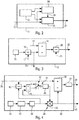
- La
figure 1 est le schéma synoptique d'un mode de réalisation particulier d'un dispositif conforme à l'invention. - Les
figures 2 à 4 sont les schémas synoptiques de modes de réalisation particuliers d'ensembles de traitement du dispositif de lafigure 1 . - Le dispositif 1 illustrant l'invention et représenté schématiquement sur la
figure 1 est destiné notamment à estimer automatiquement des paramètres liés à un vol d'un aéronef (non représenté), en particulier d'un avion de transport, de manière à fournir des paramètres qui sont précis et qui ne sont pas perturbés ou biaisés, notamment par des données air erronées. Il peut s'agir de paramètres de vol de l'aéronef, tels qu'une vitesse air, une incidence ou un nombre de Mach de l'aéronef, ainsi que de paramètres extérieurs à l'aéronef et rencontrés par l'aéronef au cours du vol, tels que la température totale par exemple.
- The figures of the appended drawing will make it clear how the invention can be realized. In these figures, identical references designate similar elements.
- The
figure 1 is the block diagram of a particular embodiment of a device according to the invention. - The
Figures 2 to 4 are the block diagrams of particular embodiments of device processing sets of thefigure 1 . - The device 1 illustrating the invention and schematically represented on the
figure 1 is intended in particular for automatically estimating parameters related to a flight of an aircraft (not shown), in particular an aircraft of transport, so as to provide parameters which are accurate and which are not disturbed or biased, in particular by erroneous air data. These may be flight parameters of the aircraft, such as airspeed, incidence or Mach number of the aircraft, as well as parameters outside the aircraft and encountered by the aircraft during flight. flight, such as the total temperature for example.
Ledit dispositif 1 qui est embarqué sur l'aéronef comporte, de façon usuelle, un ensemble 2 usuel de sources d'informations, par exemple un système de données air et de données inertielles de type ADIRS (pour « Air Data Inertial Reference system » en anglais), qui comporte :
un ensemble 3 de capteurs C1, C2,..., CN, N étant un entier, en particulier des sondes et notamment des modes de pression totale, de température totale et d'incidence ; etun ensemble 4 de moyens usuels, comprenant par exemple une centrale anémobarométrique de type ADC (« Air Data Computer » en anglais), qui détermine et fournit les valeurs de paramètres, à l'aide notamment de mesures réaliséespar ledit ensemble 3 de capteurs.
- a
set 3 of sensors C1, C2, ..., CN, N being an integer, in particular probes and in particular modes of total pressure, total temperature and incidence; and - a
set 4 of usual means, comprising for example an anemobarometric central type ADC ("Air Data Computer" in English), which determines and provides the parameter values, in particular using measurements made by said set 3 sensors.
Le dispositif 1 comprend également :
- une unité de traitement 5 qui est reliée par l'intermédiaire d'une
liaison 6audit ensemble 2 ; et - une unité d'affichage 7 qui est reliée par l'intermédiaire d'une liaison 8 à ladite unité de traitement 5 et qui est formée de manière à afficher sur au moins un écran de visualisation 9 du poste de pilotage de l'aéronef des valeurs de paramètres déterminés par le dispositif 1. Un ou des filtres peuvent être prévus pour filtrer une valeur à afficher avant de la présenter sur l'écran de visualisation 9, de manière à obtenir un confort visuel satisfaisant.
- a
processing unit 5 which is connected via alink 6 to said set 2; and - a display unit 7 which is connected via a link 8 to said
processing unit 5 and which is formed so as to display on at least onedisplay screen 9 of the cockpit of the aircraft of parameters determined by the device 1. One or more filters may be provided for filtering a value to be displayed before presenting it on thedisplay screen 9, so as to obtain a satisfactory visual comfort.
Ces valeurs peuvent également être transmises à un ensemble de dispositifs utilisateurs 14 de l'aéronef (par exemple des calculateurs et/ou des systèmes d'alarme) via une liaison 10.These values can also be transmitted to a set of
Selon l'invention, l'unité de traitement 5 du dispositif 1 comporte au moins un ensemble d'estimation 11 (ou unité d'estimation) pour déterminer automatiquement une incidence estimée corrigée.According to the invention, the
A cet effet, selon l'invention, ledit ensemble d'estimation 11 comprend, comme représenté sur la
- des moyens de réception (liaison 12) configurés pour recevoir une incidence mesurée de l'aéronef, fournie par l'ensemble 2 (
la liaison 12 étant par exemple liée à la liaison 6) ; - une unité de calcul 13 configurée pour calculer une incidence estimée à partir de paramètres aérodynamiques et de paramètres inertiels liés à l'aéronef (et également reçu de l'ensemble 2) ;
- une unité de vérification 24 configurée pour vérifier si l'incidence mesurée (reçue via la liaison 12) est considérée comme cohérente ou incohérente ; et
- une unité de calcul 25 configurée pour, en fonction de la vérification réalisée par l'unité de vérification 24 (et reçue via une liaison 26) :
- tant que l'incidence mesurée est considérée comme cohérente, déterminer une valeur de correction et ajouter cette valeur de correction à ladite incidence estimée pour obtenir l'incidence estimée corrigée ; et
- dès que l'incidence mesurée est considérée comme incohérente, et tant que cela reste le cas, ajouter une valeur corrective figée à ladite incidence estimée pour obtenir l'incidence estimée corrigée.
- receiving means (link 12) configured to receive a measured incidence of the aircraft, provided by the assembly 2 (the
link 12 being for example linked to the link 6); - a
calculation unit 13 configured to calculate an estimated incidence from aerodynamic parameters and inertial parameters related to the aircraft (and also received from the assembly 2); - a
verification unit 24 configured to check whether the measured incidence (received via link 12) is considered consistent or inconsistent; and - a
calculation unit 25 configured for, depending on the verification performed by the verification unit 24 (and received via a link 26):- as long as the measured impact is considered consistent, determine a correction value and add that correction value to the estimated impact to obtain the estimated corrected impact; and
- as soon as the measured impact is considered inconsistent, and as long as this remains the case, add a fixed corrective value to the estimated impact to obtain the estimated corrected impact.
Ledit ensemble d'estimation 11 peut transmettre l'incidence estimée corrigée via une liaison 27 à différents éléments d'estimation et/ou de traitement du dispositif 1 et/ou à des moyens utilisateurs externes au dispositif 1 (par exemple par l'intermédiaire des liaisons 8 et 10).Said estimation set 11 can transmit the corrected estimated incidence via a
Ainsi :
- si l'incidence mesurée est considérée comme crédible (cohérente), une valeur de correction est calculée pour faire converger une incidence estimée corrigée avec l'incidence mesurée ; et
- si l'incidence mesurée est considérée comme non crédible (incohérente), la valeur de correction est figée à sa dernière valeur considérée comme correcte, c'est-à-dire à la valeur de correction calculée pour la dernière incidence considérée comme crédible, et l'incidence estimée corrigée est rendue indépendante de l'incidence mesurée.
- if the measured impact is considered credible (consistent), a correction value is calculated to converge a corrected estimated impact with the measured impact; and
- if the measured impact is considered non-credible (incoherent), the correction value is frozen at its last value considered as correct, that is, the correction value calculated for the last incidence considered credible, and the estimated corrected incidence is made independent of the measured impact.
Par conséquent, grâce à l'ensemble d'estimation 11 du dispositif 1, on dispose à bord de l'aéronef d'une valeur d'incidence (incidence estimée corrigée), qui est susceptible d'être déterminée même en cas de défaillance (de givrage notamment) de sondes d'incidence. De plus, cette valeur d'incidence présente une précision suffisamment élevée pour qu'elle puisse être utilisée par divers systèmes de l'aéronef.Consequently, thanks to the estimation set 11 of the device 1, the aircraft has an incidence value (corrected estimated incidence) on board the aircraft, which can be determined even in the event of a failure ( icing in particular) of incidence probes. Moreover, this incidence value has a sufficiently high precision that it can be used by various systems of the aircraft.
L'unité de vérification 24 considère l'incidence mesurée comme incohérente, si l'une des conditions suivantes est remplie :
- la différence entre une incidence estimée et l'incidence mesurée est supérieure à une valeur de seuil prédéterminée pendant une durée prédéterminée ; et
- un calculateur de données air de type ADC, faisant par exemple partie de l'ensemble 2, considère l'incidence mesurée comme incohérente et émet un message correspondant, par exemple lorsque la vitesse descend sous 60 noeuds.
- the difference between an estimated incidence and the measured incidence is greater than a predetermined threshold value for a predetermined duration; and
- an air data calculator ADC type, for example part of the
assembly 2, considers the measured incidence as incoherent and sends a corresponding message, for example when the speed drops below 60 knots.
Une alarme (sonore et/ou visuelle) est déclenchée lorsque la différence entre l'incidence mesurée et l'incidence estimée excède un seuil (par exemple 1°), pendant au moins une durée prédéterminée (par exemple 10s).An alarm (sound and / or visual) is triggered when the difference between the measured incidence and the estimated incidence exceeds a threshold (for example 1 °), for at least a predetermined duration (for example 10s).
Par ailleurs, l'unité de calcul 13 comporte, comme représenté sur la
- un moyen 15 pour déterminer, de façon usuelle, une vitesse verticale Vzbi à l'aide de données inertielles de l'aéronef ;
- un moyen de calcul 16 pour calculer une pente air γ représentant le rapport entre cette vitesse verticale Vzbi et une vitesse vraie Vtas . La vitesse vraie Vtas , reçue par l'intermédiaire d'une
liaison 17, correspond à une vitesse vraie estimée Vtas1 (précisée ci-dessous) au moins en absence de valeur de vitesse vraie fournie par un calculateur de données air (de l'ensemble 2) ; - un moyen de calcul 18 pour soustraire la pente air γ déterminée par le moyen de calcul 16 à un angle d'inclinaison longitudinal θ de l'aéronef, reçu par l'intermédiaire d'une liaison 19 (par exemple de l'ensemble 2) ; et
- un moyen de calcul 20 pour calculer le rapport entre la différence reçue du moyen de calcul 18 et le cosinus de l'angle de roulis φ de l'aéronef, reçu par une liaison 21 (par exemple de l'ensemble 2).
- means 15 for determining, in the usual way, a vertical speed Vzbi using inertial data of the aircraft;
- calculation means 16 for calculating an air slope γ representing the ratio between this vertical speed Vzbi and a true speed Vtas. The true speed Vtas, received via a
link 17, corresponds to a speed true estimate Vtas 1 (specified below) at least in the absence of true velocity value provided by an air data calculator (of set 2); - calculation means 18 for subtracting the air slope γ determined by the calculation means 16 at a longitudinal inclination angle θ of the aircraft, received via a link 19 (for example of the assembly 2) ; and
- calculating means 20 for calculating the ratio between the difference received from the calculation means 18 and the cosine of the roll angle φ of the aircraft, received by a link 21 (for example of the assembly 2).
L'unité de calcul 13 comprend donc des éléments de calcul pour calculer l'incidence estimée α à l'aide de l'expression suivante : ![]()
- θ est l'angle d'inclinaison longitudinale de l'aéronef, encore appelé assiette de l'aéronef ;
- φ est l'angle de roulis de l'aéronef ;
- cos est le cosinus ; et
- γ est la pente air de l'aéronef.
- θ is the longitudinal angle of inclination of the aircraft, also called the attitude of the aircraft;
- φ is the roll angle of the aircraft;
- cos is the cosine; and
- γ is the air slope of the aircraft.
L'unité de calcul 13 peut transmettre cette incidence estimée α (via une liaison 22) à différents éléments d'estimation et/ou de traitement du dispositif 1 (unités 24 et 25 notamment) et/ou à des moyens utilisateurs externes au dispositif 1 (par exemple par l'intermédiaire des liaisons 8 et 10).The
De même, la pente air γ calculée par l'élément de calcul 16 peut être transmise via une liaison 23 à différents éléments d'estimation et/ou de traitement du dispositif 1 et/ou à des moyens utilisateurs externes au dispositif 1 (par exemple par l'intermédiaire des liaisons 8 et 10).Similarly, the air slope γ calculated by the
L'élément de calcul 16 est donc configuré pour calculer la pente air γ à l'aide de l'expression suivante : ![]()
- Vzbi est la vitesse verticale déterminée à partir de données inertielles de l'aéronef ; et
- Vtas est la vitesse vraie, qui correspond à une vitesse vraie estimée Vtas1 au moins en absence de valeur de vitesse vraie fournie par un calculateur de données air.
- Vzbi is the vertical velocity determined from inertial data of the aircraft; and
- Vtas is the true speed, which corresponds to an estimated true speed Vtas 1 at least in the absence of a true speed value provided by an air data calculator.
L'unité de traitement 5 du dispositif 1 comprend, de plus, un élément de calcul 28 pour calculer une vitesse vraie estimée Vtas1 à l'aide de l'expression suivante : ![]()
- γ est la pente air de l'aéronef ;
- k1, k2 et R sont des valeurs prédéterminées, à savoir :
- k1 = 1/0,5144 ;
- k2 = 0,2 ;
- R = 287J ;
- TAT est une température totale mesurée ; et
- M1 est un nombre de Mach estimé, précisé ci-dessous.
- γ is the air slope of the aircraft;
- k1, k2 and R are predetermined values, namely:
- k1 = 1 / 0.5144;
- k2 = 0.2;
- R = 287J;
- TAT is a measured total temperature; and
- M1 is an estimated Mach number, specified below.
En outre, l'unité de traitement 5 du dispositif 1 comprend également un élément de calcul 29 pour calculer une température totale estimée TAT1 (exprimée en °K) à l'aide de l'expression suivante : ![]()
- k3 à k5 sont des valeurs prédéterminées, à savoir ;
- k3 = 288 ;
- k4 = 1,98/1000 ;
- k5 = 0,2 ;
- Zp est une altitude de l'aéronef, exprimée en pieds ; et
- M1 est le nombre de Mach estimé.
- k3 to k5 are predetermined values, i.e.
- k3 = 288;
- k4 = 1.98 / 1000;
- k5 = 0.2;
- Zp is an altitude of the aircraft, expressed in feet; and
- M1 is the estimated Mach number.
En outre, le dispositif 1 comprend également un élément de calcul, en particulier l'élément de calcul 29, pour calculer la valeur ΔISA1 précitée à l'aide de l'expression suivante : ![]()
- TAT est une température totale mesurée, exprimée en °K ;
- l'expression (TAT/(1+k6*s)) correspond à la température totale mesurée TAT, filtrée par un filtre du premier ordre de constante de temps k6 ; et - k6 à k9 sont des valeurs prédéterminées, à savoir :
- k6 = 30;
- k7 = 0,2;
- k8 = 288; et
- k9 = 1,98/1000
- TAT is a total measured temperature, expressed in ° K;
- the expression ( TAT / (1+
k 6 * s )) corresponds to the total measured temperature TAT, filtered by a filter of the first order of timeconstant k 6; and - k6 to k9 are predetermined values, namely:- k6 = 30;
- k7 = 0.2;
- k8 = 288; and
- k9 = 1.98 / 1000
Les valeurs k1 à k9 présentent des unités appropriées, et le cas échéant aucune dimension.The values k1 to k9 have appropriate units, and if necessary no dimension.
Par ailleurs, le dispositif 1 comprend une unité de surveillance 30 d'une température totale mesurée (et reçue par exemple de l'ensemble 2) pour détecter un éventuel givrage d'une sonde de température totale.Furthermore, the device 1 comprises a
L'unité de surveillance 30 (qui fait de préférence partie de l'unité de traitement 5) comprend un élément de calcul pour calculer la différence entre la température totale estimée, reçue de l'élément de calcul 29, et une température totale mesurée, reçue de l'ensemble 2, et un élément de comparaison pour comparer cette différence à une valeur de seuil.The monitoring unit 30 (which is preferably part of the processing unit 5) comprises a calculation element for calculating the difference between the total estimated temperature, received from the
Dans un mode de réalisation particulier, l'unité de surveillance 30 indique que :
- la température totale mesurée est considérée comme gelée (givrage des sondes de température totale) si la différence précitée, dépasse un premier seuil,
par exemple 10°C ; et - la température totale mesurée est de nouveau considérée comme dégelée, si la différence précitée repasse sous un second seuil,
par exemple 5°C.
- the total measured temperature is considered as frozen (icing of the total temperature probes) if the above difference exceeds a first threshold, for example 10 ° C; and
- the measured total temperature is again considered thawed, if the above difference returns to a second threshold, for example 5 ° C.
De plus, l'unité de traitement 5 du dispositif 1 comprend également un élément de calcul 31 pour calculer un nombre de Mach estimé M1, à l'aide des expressions suivantes :
- quand l'altitude Zp de l'aéronef est comprise entre le sol (0 pied) et une première valeur prédéterminée, de préférence 30 000 pieds :

- et quand l'altitude Zp de l'aéronef est comprise entre ladite première valeur et une seconde valeur prédéterminée (supérieure à cette première valeur), de préférence 36 000 pieds :

- Vc1 est une vitesse air estimée, exprimée en noeuds ;
- Zp est l'altitude de l'aéronef, exprimée en pieds et définie entre 0
pied et 36 000 pieds (niveau de vol : FL360) ; et - k10 à k13 sont des paramètres prédéterminés, à savoir :
- k10 = 661,5 ;
- k11 = 5*10-6 ;
- k12 = 1,2*10-6 ;
- k13 = 30000.
- when the altitude Zp of the aircraft is between the ground (0 feet) and a first predetermined value, preferably 30,000 feet:
- and when the altitude Zp of the aircraft is between said first value and a second predetermined value (greater than this first value), preferably 36,000 feet:
- Vc1 is an estimated air speed, expressed in knots;
- Zp is the altitude of the aircraft, expressed in feet and defined between 0 feet and 36,000 feet (flight level: FL360); and
- k10 to k13 are predetermined parameters, namely:
- k10 = 661.5;
- k11 = 5 * 10 -6 ;
- k12 = 1.2 * 10 -6 ;
- k13 = 30000.
En outre, dans un mode de réalisation particulier, le dispositif 1 comporte, de plus, un ensemble d'estimation 33 (ou unité d'estimation) pour déterminer automatiquement une vitesse air estimée de l'aéronef.In addition, in a particular embodiment, the device 1 further comprises an estimation unit 33 (or estimation unit) for automatically determining an estimated air speed of the aircraft.
Cet ensemble d'estimation 33 comprend, comme représenté sur la
- une unité de calcul 34 configurée pour calculer une vitesse air dite vitesse aérodynamique, à partir de valeurs courantes (reçues de l'ensemble 2) de paramètres aérodynamiques et de paramètres inertiels de l'aéronef ;
- un moyen (à savoir une liaison 35) pour recevoir une vitesse conventionnelle courante, déterminée par une centrale anémobarométrique et reçue de l'ensemble 2 ;
- une unité de calcul 36 configurée pour soustraire à cette vitesse conventionnelle une vitesse estimée à une itération précédente de manière à obtenir une vitesse résiduelle ;
- une unité de calcul 37 configurée pour comparer cette vitesse résiduelle à une valeur de seuil λ,
par exemple 20 noeuds ; et - une unité de calcul configurée 39, pour en fonction de cette comparaison :
- tant que cette vitesse résiduelle est inférieure ou égale à ladite valeur de seuil, calculer une valeur corrective qui est appliquée (par une multiplication comme précisé ci-dessous) à ladite vitesse aérodynamique pour obtenir la vitesse air estimée ; et
- dès que cette vitesse résiduelle est supérieure à ladite valeur de seuil, illustrant la détection d'un problème de validité de la vitesse conventionnelle, et tant que cela reste le cas, appliquer une valeur corrective figée à ladite vitesse aérodynamique pour obtenir la vitesse air estimée.
- a
calculation unit 34 configured to calculate an airspeed called aerodynamic speed, based on current values (received from the set 2) of aerodynamic parameters and inertial parameters of the aircraft; - means (i.e., a link 35) for receiving a conventional conventional speed determined by an anemobarometric central and received from the
set 2; - a
computing unit 36 configured to subtract from this conventional speed a speed estimated at a previous iteration so as to obtain a residual speed; - a
calculation unit 37 configured to compare this residual speed with a threshold value λ, for example 20 nodes; and - a calculation unit configured 39, according to this comparison:
- as long as this residual speed is less than or equal to said threshold value, calculating a corrective value which is applied (by a multiplication as specified below) to said aerodynamic speed to obtain the estimated air speed; and
- as soon as this residual speed is greater than said threshold value, illustrating the detection of a problem of validity of the conventional speed, and as long as this remains the case, applying a fixed corrective value at said aerodynamic speed to obtain the estimated air speed .
Une alarme (sonore et/ou visuelle) qui est par exemple reliée à l'unité de calcul 37 via une liaison 38, est déclenchée lorsque la différence entre la vitesse mesurée et la vitesse estimée excède un seuil (par exemple 20 noeuds) pendant une durée prédéterminée.An alarm (sound and / or visual) which is for example connected to the
L'unité de calcul 34 calcule ladite vitesse aérodynamique Vcaero, de façon usuelle, à l'aide de l'expression suivante : ![]()
- Ma est la masse de l'aéronef en kg ;
- nz est le facteur de charge vertical ;
- ρ0 est la densité de l'air, qui est égale à 1,225 kg/m3 ;
- Czα représente le gradient de portance et vaut
environ 6 ; - α est une valeur d'incidence de l'aéronef ; et
- α0 est l'incidence à portance nulle, qui dépend de la configuration des becs et volets et du braquage des aérofreins.
- Ma is the mass of the aircraft in kg;
- nz is the vertical load factor;
- ρ 0 is the density of the air, which is equal to 1.225 kg / m 3 ;
- Czα represents the lift gradient and is about 6;
- α is an incidence value of the aircraft; and
- α 0 is the incidence at zero lift, which depends on the configuration of the nozzles and flaps and the steering of the airbrakes.
Dans un mode de réalisation préféré, l'unité de calcul 34 calcule la vitesse aérodynamique en utilisant comme valeur d'incidence α, l'incidence estimée corrigée, déterminée par l'ensemble d'estimation 11.In a preferred embodiment, the
L'ensemble d'estimation 33 comprend à la sortie de l'élément de calcul 34 des moyens de limitation 47 :
- pour limiter le signal (vitesse aérodynamique) reçu de l'élément de calcul 34 entre deux valeurs de vitesse, par exemple entre 80 et 400 noeuds ; et
- pour limiter la pente de ce signal.
- for limiting the signal (aerodynamic velocity) received from computing
element 34 between two velocity values, for example between 80 and 400 knots; and - to limit the slope of this signal.
L'ensemble d'estimation 33 comprend également un filtre 48 à la sortie des moyens de limitation 47.The
Par ailleurs, l'unité de calcul 39 comprend :
- un élément de calcul 40 pour diviser la vitesse conventionnelle par la valeur à la sortie du filtre 48 ;
- un système de filtrage 41 ; et
un multiplicateur 42 qui multiplie la valeur relative à la vitesse aérodynamique (reçue du filtre 48) par la sortie du système de filtrage 41 pour obtenir la vitesse air estimée.
- a
computing element 40 for dividing the conventional speed by the value at the output of thefilter 48; - a
filtering system 41; and - a
multiplier 42 which multiplies the value relative to the aerodynamic speed (received from the filter 48) by the output of thefiltering system 41 to obtain the estimated air speed.
Cette vitesse air estimée peut être transmise par une liaison 43 à différents éléments d'estimation et/ou de traitement du dispositif 1 et/ou à des moyens utilisateurs externes au dispositif 1 (par exemple par l'intermédiaire des liaisons 8 et 10).This estimated air speed can be transmitted by a
Par ailleurs, le système de filtrage 41 comprend :
- un élément de calcul 44 pour calculer la différence entre la sortie de l'élément de calcul 40 et la sortie du système de filtrage 41 ; et
- un moyen de
commutation 45 qui commute à 0 en cas de givrage (détecté par l'élément 37) ; et un intégrateur 46.
- a
computing element 44 for calculating the difference between the output of thecomputing element 40 and the output of thefiltering system 41; and - switching means 45 which switches to 0 in the event of icing (detected by element 37); and
- an
integrator 46.
Lors d'une détection d'un givrage par l'élément 37, le moyen de commutation 45 est commandé pour amener l'entrée de l'intégrateur 46, non plus à la sortie du moyen de calcul 44, mais à une valeur nulle, de sorte que l'intégrateur 46 utilise alors la valeur corrective figée (qui est enregistrée). Cette valeur corrective figée correspond à la dernière valeur corrective calculée, avant la détection d'un problème de validité de la vitesse conventionnelle Vc.During an icing detection by the
L'unité de calcul 39 prévoit donc de multiplier la vitesse aérodynamique par ladite valeur corrective (à l'aide du multiplicateur 42). Ainsi, contrairement à la solution préconisée dans le brevet
L'intégrateur 46 calcule la valeur corrective Vcorr à l'aide de l'expression d'intégration suivante : ![]()
- Vc est la vitesse conventionnelle ;
- Vcaero est la vitesse aérodynamique ; et
- τ est la constante de temps.
- Vc is the conventional speed;
- Vcaero is aerodynamic speed; and
- τ is the time constant.
L'expression d'intégration précitée est écrite sous forme d'une représentation de Laplace avec τ la constante de temps et s la dérivée.The above integration expression is written as a Laplace representation with τ the time constant and s the derivative.
Ainsi, grâce audit ensemble d'estimation 33 du dispositif 1, on dispose à bord de l'aéronef d'une information de vitesse air alternative Vcest (par rapport aux vitesses usuelles), qui :
- d'une part, présente une précision suffisamment élevée pour qu'elle puisse être utilisée par divers systèmes de l'aéronef ; et
- d'autre part, est susceptible d'être déterminée même en cas de problème de validité de la vitesse conventionnelle Vc, c'est-à-dire même en cas de défaillance d'une centrale anémobarométrique ou de sondes de pression associées, notamment des sondes Pitot.
- on the one hand, has a sufficiently high precision that it can be used by various systems of the aircraft; and
- on the other hand, is likely to be determined even in the event of a problem of validity of the conventional speed Vc, that is to say even in the event of failure of an anemobarometric central unit or of associated pressure probes, in particular Pitot probes.
L'ensemble d'estimation 33 du dispositif 1 permet ainsi simultanément :
- d'une part, en l'absence de problème de validité de la vitesse conventionnelle Vc, par la correction réalisée sur la vitesse aérodynamique Vcaero de manière à la faire converger vers la vitesse conventionnelle Vc, de remédier à un problème de précision réduite d'une vitesse aérodynamique Vcaero ; et
- d'autre part, en cas de problème de validité (ou de perte) de la vitesse conventionnelle Vc (notamment lors d'un problème sur les sondes Pitot) de ne pas en tenir compte de cette dernière.
- on the one hand, in the absence of a problem of validity of the conventional speed Vc, by the correction performed on the aerodynamic speed Vcaero so as to converge it to the conventional speed Vc, to remedy a problem of reduced accuracy of Vcaero aerodynamic speed; and
- on the other hand, in the event of a problem of validity (or loss) of the conventional speed Vc (in particular during a problem on pitot probes), to ignore this latter.
Dans ce dernier cas, on dispose toujours d'une vitesse air estimée Vcest précise, puisque l'on continue à corriger la vitesse aérodynamique Vcaero, en la multipliant par une valeur corrective figée qui est la plus précise possible, étant donné qu'elle correspond à la dernière valeur corrective calculée avant la détection du problème de validité de la vitesse conventionnelle Vc.In the latter case, we always have an estimated air speed Vcest accurate, since we continue to correct the aerodynamic speed Vcaero, multiplying it by a corrected corrective value that is as accurate as possible, given that it corresponds to the last corrective value calculated before the detection of the validity problem of the conventional speed Vc.
Par ailleurs, au décollage de l'aéronef, c'est-à-dire lors de l'activation du dispositif 1, ce dernier initialise l'intégrateur 46, à une valeur Vc/Vcaero de telle sorte que la vitesse air estimée Vcest est alors égale à la vitesse conventionnelle Vc.Moreover, at takeoff of the aircraft, that is to say during the activation of the device 1, the latter initializes the
Par ailleurs, dans le cadre de la présente invention, on peut également prévoir une solution alternative à la vitesse air estimée. Il est, en effet, également possible de calculer un nombre de Mach estimé M2 plutôt qu'une vitesse estimée à partir de l'équation de portance suivante (avec PS la pression statique) : 
Dans ce cas, on réalise :
- une intégration du rapport Mach/M2 pour obtenir le nombre de Mach estimé tant que le givrage n'est pas détecté ;
- un calcul de la vitesse vraie et de l'incidence comme décrit précédemment ; et
- une même surveillance de la température totale givrée.
- an integration of the Mach / M2 ratio to obtain the estimated Mach number as long as the icing is not detected;
- a calculation of the true speed and incidence as previously described; and
- the same monitoring of the total frosted temperature.
Le calcul de la vitesse Vc2 estimée est réalisé à l'aide de la formule de Fabre-Bilange (exprimée en noeuds) : ![]()
![]()
Cette expression est correcte quelle que soit l'altitude.This expression is correct regardless of the altitude.
Le dispositif 1, tel que décrit ci-dessus, présente une adaptation rapide à tout type d'aéronef. De plus, l'invention ne prévoit pas de supprimer les sondes aérodynamiques (sondes de pression totale, sondes d'incidence, sondes de température totale,...), mais d'apporter une solution permettant à l'aéronef de voler un certain temps sous des conditions de givrage sévères, sans de telles sondes, même avec des gradients de vents ou des turbulences.The device 1, as described above, has a rapid adaptation to any type of aircraft. In addition, the invention does not provide for eliminating the aerodynamic probes (total pressure probes, incidence probes, total temperature probes, etc.), but to provide a solution allowing the aircraft to fly a certain number of aircraft. weather under severe icing conditions, without such probes, even with wind gradients or turbulence.
Claims (11)
- A method for automatically estimating at least one parameter related to a flight of an aircraft, including at least one incidence of the aircraft, said method comprising at least one first series of successive steps for automatically determining a corrected estimated incidence, said first series of successive steps consisting, in an automatic and iterative manner:a) in computing an estimated incidence on the basis of aerodynamic parameters and of inertial parameters related to the aircraft;b) in measuring an incidence of the aircraft;c) in verifying whether the measured incidence is considered to be consistent or inconsistent;d) as a function of the verification carried out in step c):- as long as the measured incidence is considered to be consistent, in determining a correction value and in adding this correction value to said estimated incidence to obtain the corrected estimated incidence; and- as soon as the measured incidence is considered to be inconsistent, and as long as this remains the case, in adding a fixed corrective value to said estimated incidence to obtain the corrected estimated incidence,said method comprising, moreover, a second series of successive steps for automatically determining an estimated air speed of an aircraft, said second series of successive steps consisting, in an automatic and iterative manner:A/ in computing an air speed termed the aerodynamic speed, on the basis of current values of aerodynamic parameters and of inertial parameters of the aircraft, including an incidence value by using the corrected estimated incidence, determined in step d) of the first series of successive steps, as incidence value;B/ in determining a current conventional speed, with the aid of an anemobarometric platform;C/ in subtracting a speed estimated at the previous iteration from this conventional speed so as to obtain a residual speed;D/ in comparing this residual speed with a threshold value; andE/ as a function of the comparison realized at step D/:- as long as this residual speed is less than or equal to said threshold value, in computing a corrective value which is applied to said aerodynamic speed to obtain the estimated air speed; and- as soon as this residual speed is greater than said threshold value, and as long as this remains the case, in applying a fixed corrective value which is applied to said aerodynamic speed to obtain the estimated air speed,
- The method as claimed in claim 1,
wherein step a) consists in computing the estimated incidence α with the aid of the following expression: - θ is an angle of longitudinal inclination of the aircraft;- φ is an angle of roll of the aircraft;- cos is the cosine; and- γ is an air slope of the aircraft.
 - The method as claimed in claim 2,
which comprises a step consisting in computing the air slope γ with the aid of the following expression: - Vzbi is a vertical speed determined on the basis of inertial data of the aircraft; and- Vtas is a true speed, which corresponds to an estimated true speed at least in the absence of any true speed value provided by an air data computer.
 - The method as claimed in any of the previous claims,
which comprises a step consisting in computing an estimated total temperature TAT1 with the aid of the following expression: - k3 to k5 are predetermined values;- Zp is an altitude of the aircraft;- M1 is an estimated Mach number; and- ΔISA1=((TAT/(1+k6*s))*(1/(1+k7*M12)))-k8+k9*Zpin which:• TAT is a measured total temperature;• the expression (TAT/(1+k6*s)) corresponds to the value TAT filtered by a first-order filter, with time constant k6; and• k6 to k9 are predetermined values.
 - The method as claimed in any of the previous claims,
which comprises a step consisting in computing an estimated Mach number M1 with the aid of the following expressions:- when an altitude Zp of the aircraft lies between the ground and a first predetermined value: - when the altitude Zp of the aircraft lies between said first value and a second predetermined value greater than said first value:in which:
 • Vc1 is an estimated air speed;• Zp is the altitude of the aircraft lying between the ground and said second value; and• k10 to k13 are predetermined parameters.
 - The method as claimed in any of the previous claims,
wherein in step c), the measured incidence is considered to be inconsistent if one of the following conditions is fulfilled:- the difference between an estimated incidence and the measured incidence is greater than a predetermined threshold value for a predetermined duration; and- an air data computer considers the measured incidence to be inconsistent. - The method as claimed in any of the previous claims,
which comprises a step of monitoring at least one measured total temperature to detect possible icing of a total temperature probe. - The method as claimed in any of claims 1 to 7,
wherein step E/ comprises an operation consisting in computing the corrective value Vcorr with the aid of the following integration expression: - Vc is the conventional speed;- Vcaero is the aerodynamic speed; and- τ is a time constant.
 - A device for automatically estimating at least one parameter related to a flight of an aircraft, including at least one incidence of the aircraft, said device comprising at least one first estimation assembly for automatically determining a corrected estimated incidence, said first estimation assembly comprising:- a first computation unit configured to compute an estimated incidence on the basis of aerodynamic parameters and of inertial parameters related to the aircraft;- a reception unit configured to receive a measured incidence of the aircraft; and- a verification unit configured to verify whether the measured incidence is considered to be consistent or inconsistent,
wherein said first estimation assembly comprises, moreover, a second computation unit configured to, as a function of the verification carried out by the verification unit:• as long as the measured incidence is considered to be consistent, determine a correction value and add this correction value to said estimated incidence to obtain the corrected estimated incidence; and• as soon as the measured incidence is considered to be inconsistent, and as long as this remains the case, add a fixed corrective value to said estimated incidence to obtain the corrected estimated incidence,and which comprises, moreover, a second estimation assembly for automatically determining an estimated air speed of an aircraft, said second estimation assembly comprising:- a third computation unit configured to compute an air speed termed the aerodynamic speed, on the basis of current values of aerodynamic parameters and of inertial parameters of the aircraft, including an incidence value;- a reception unit configured to receive a current conventional speed determined by an anemobarometric platform;- a fourth computation unit configured to subtract a speed estimated at a previous iteration from this conventional speed so as to obtain a residual speed;- a fifth computation unit configured to compare this residual speed with a threshold value; and- a sixth computation unit configured to, as a function of this comparison:• as long as this residual speed is less than or equal to said threshold value, compute a corrective value which is applied to said aerodynamic speed to obtain the estimated air speed; and• as soon as this residual speed is greater than said threshold value, illustrating the detection of a problem of validity of the conventional speed, and as long as this remains the case, apply a fixed corrective value to said aerodynamic speed to obtain the estimated air speed,the third computation unit being configured to compute the aerodynamic speed using the corrected estimated incidence, determined by the first estimation assembly, as incidence value. - The device as claimed in claim 9,
which comprises, moreover, at least one of the following assemblies:- an estimation assembly for determining an estimated true speed;- an estimation assembly for determining an estimated total temperature; and- an estimation assembly for determining an estimated Mach number. - An aircraft,
which comprises a device such as that specified under any of claims 9 and 10.
Applications Claiming Priority (1)
| Application Number | Priority Date | Filing Date | Title |
|---|---|---|---|
| FR1452200A FR3018912B1 (en) | 2014-03-18 | 2014-03-18 | METHOD AND DEVICE FOR AUTOMATICALLY ESTIMATING PARAMETERS RELATED TO A FLIGHT OF AN AIRCRAFT |
Publications (2)
| Publication Number | Publication Date |
|---|---|
| EP2921863A1 EP2921863A1 (en) | 2015-09-23 |
| EP2921863B1 true EP2921863B1 (en) | 2017-11-15 |
Family
ID=50780743
Family Applications (1)
| Application Number | Title | Priority Date | Filing Date |
|---|---|---|---|
| EP15159018.9A Active EP2921863B1 (en) | 2014-03-18 | 2015-03-13 | Method and device for automatically estimating parameters linked to the flight of an aircraft |
Country Status (4)
| Country | Link |
|---|---|
| US (1) | US9945664B2 (en) |
| EP (1) | EP2921863B1 (en) |
| CN (1) | CN104931007B (en) |
| FR (1) | FR3018912B1 (en) |
Families Citing this family (11)
| Publication number | Priority date | Publication date | Assignee | Title |
|---|---|---|---|---|
| US10365296B2 (en) * | 2016-09-29 | 2019-07-30 | Innovative Solutions & Support, Inc. | Systems and methods for compensating for the absence of a sensor measurement in a heading reference system |
| US10605822B2 (en) * | 2017-06-12 | 2020-03-31 | The Boeing Company | System for estimating airspeed of an aircraft based on a weather buffer model |
| US11927460B2 (en) * | 2017-10-25 | 2024-03-12 | Bae Systems Plc | Control of diverse types of crew interface for flight control |
| EP3710901B1 (en) | 2017-11-14 | 2022-08-03 | Gulfstream Aerospace Corporation | Potential aircraft trajectory wind effect computation |
| WO2019099534A1 (en) * | 2017-11-14 | 2019-05-23 | Gulfstream Aerospace Corporation | Conversion between calibrated airspeed and true airspeed in trajectory modeling |
| FR3074141B1 (en) * | 2017-11-27 | 2019-12-20 | Airbus Operations | METHOD AND SYSTEM FOR ESTIMATING THE SHUTTER POSITION OF AN AIRCRAFT |
| CN107817006B (en) * | 2017-11-30 | 2021-01-08 | 中国航空工业集团公司沈阳飞机设计研究所 | Self-detection method of attack angle sensor |
| KR101982071B1 (en) * | 2018-08-24 | 2019-05-24 | 주식회사 에그 (Egg) | method for autonomous icing protection apparatus |
| KR101982181B1 (en) * | 2018-08-30 | 2019-05-24 | 국방과학연구소 | Method and apparatus for compensating air data using inertial navigation data |
| US11003196B2 (en) * | 2018-12-07 | 2021-05-11 | The Boeing Company | Flight control system for determining a common mode pneumatic fault |
| CN111122899B (en) * | 2019-12-11 | 2020-11-17 | 南京航空航天大学 | Incidence angle sideslip angle estimation method for flying in atmospheric disturbance |
Family Cites Families (8)
| Publication number | Priority date | Publication date | Assignee | Title |
|---|---|---|---|---|
| US6273370B1 (en) * | 1999-11-01 | 2001-08-14 | Lockheed Martin Corporation | Method and system for estimation and correction of angle-of-attack and sideslip angle from acceleration measurements |
| FR2881849B1 (en) * | 2005-02-04 | 2007-04-06 | Airbus France Sas | METHOD AND DEVICE FOR CONTROLLING A PLANE IN BLANK |
| US8761970B2 (en) * | 2008-10-21 | 2014-06-24 | The Boeing Company | Alternative method to determine the air mass state of an aircraft and to validate and augment the primary method |
| FR2938924B1 (en) * | 2008-11-24 | 2011-02-11 | Airbus France | METHOD AND DEVICE FOR DETERMINING ANEMOMETRIC PARAMETERS OF AN AIRCRAFT |
| FR2950437B1 (en) * | 2009-09-23 | 2011-12-02 | Airbus Operations Sas | METHOD AND DEVICE FOR DETECTING AN ERRONEOUS SPEED PROVIDED BY AN AIR DATA SYSTEM AND INERTIAL DATA |
| FR2979993B1 (en) * | 2011-09-09 | 2013-09-20 | Airbus Operations Sas | METHOD AND DEVICE FOR AUTOMATICALLY ESTIMATING AIR SPEED OF AN AIRCRAFT |
| FR2988480B1 (en) * | 2012-03-21 | 2014-05-09 | Airbus Operations Sas | IMPACT PROBE BLOCK DETECTION SYSTEM FOR AN AIRCRAFT. |
| FR2988851B1 (en) * | 2012-03-28 | 2014-04-25 | Dassault Aviat | METHOD FOR DETERMINING A CREDIBILITY STATE OF MEASUREMENTS OF AN AIRCRAFT INCIDENT SENSOR AND CORRESPONDING SYSTEM |
-
2014
- 2014-03-18 FR FR1452200A patent/FR3018912B1/en active Active
-
2015
- 2015-03-13 EP EP15159018.9A patent/EP2921863B1/en active Active
- 2015-03-16 US US14/658,594 patent/US9945664B2/en active Active
- 2015-03-18 CN CN201510118420.4A patent/CN104931007B/en active Active
Non-Patent Citations (1)
| Title |
|---|
| None * |
Also Published As
| Publication number | Publication date |
|---|---|
| US9945664B2 (en) | 2018-04-17 |
| CN104931007A (en) | 2015-09-23 |
| US20160178364A1 (en) | 2016-06-23 |
| FR3018912B1 (en) | 2017-11-24 |
| CN104931007B (en) | 2020-04-24 |
| FR3018912A1 (en) | 2015-09-25 |
| EP2921863A1 (en) | 2015-09-23 |
Similar Documents
| Publication | Publication Date | Title |
|---|---|---|
| EP2921863B1 (en) | Method and device for automatically estimating parameters linked to the flight of an aircraft | |
| EP2568295B1 (en) | Method and apparatus for the automatic estimation of airspeed of an aircraft | |
| WO2013144128A1 (en) | Method for determining the estimated weight of an aircraft, and corresponding system | |
| FR2988851A1 (en) | METHOD FOR DETERMINING A CREDIBILITY STATE OF MEASUREMENTS OF AN AIRCRAFT INCIDENT SENSOR AND CORRESPONDING SYSTEM | |
| FR2988835A1 (en) | METHOD FOR DETERMINING A CREDIBILITY STATE OF SENSOR MEASUREMENTS OF AN AIRCRAFT AND CORRESPONDING SYSTEM | |
| FR3007841A1 (en) | METHOD FOR DETECTING A FAILURE OF AT LEAST ONE SENSOR PRESENTED ON AN AIRCRAFT, USING A BARO-INERTIAL LOOP AND ASSOCIATED SYSTEM | |
| EP2642302B1 (en) | Method and device for verifying the consistency of the measurements of the angle-of-attack probe of an aircraft | |
| FR2988833A1 (en) | DEVICE FOR DISPLAYING FLIGHT CHARACTERISTICS OF AN AIRCRAFT, INSTRUMENTATION FOR AIRCRAFT AND ASSOCIATED METHOD | |
| EP2977769B1 (en) | Method and device for estimating the mach number of an aircraft | |
| FR3029638A1 (en) | METHOD AND DEVICE FOR ESTIMATING THE AERODYNAMIC SPEED OF AN AIRCRAFT | |
| EP2176623B1 (en) | Backup instrument for aircraft | |
| FR2950437A1 (en) | METHOD AND DEVICE FOR DETECTING AN ERRONEOUS SPEED PROVIDED BY AN AIR DATA SYSTEM AND INERTIAL DATA | |
| FR3007840A1 (en) | METHOD FOR DETECTING A FAILURE OF AT LEAST ONE SENSOR PRESENTED ON AN AIRCRAFT USING AN ANEMO-INERTIAL LOOP AND ASSOCIATED SYSTEM | |
| FR3016223A1 (en) | METHOD AND DEVICE FOR DETERMINING A LINEAR FIELD PROFILE ALONG A LATERAL APPROACH TRACK OF AN AIRPORT. | |
| FR2495313A1 (en) | LONGITUDINAL INCLINATION CALCULATION CIRCUIT FOR AN AIRCRAFT | |
| FR2959316A1 (en) | METHOD AND DEVICE FOR AUTOMATICALLY ESTIMATING AIR SPEED OF AN AIRCRAFT | |
| FR3000196A1 (en) | Device for providing values of e.g. speed of aircraft to pilot, has computers computing value for navigation parameter and value of error estimation using measurement information and unique fusion algorithm for use by user systems | |
| EP2821347B1 (en) | Aircraft including a measuring probe and method for determining flight parameters of such an aircraft | |
| CA2472292C (en) | Process and apparatus for monitoring the validity of speed data for an aircraft and speed-data generating system having such an apparatus | |
| FR3023918A1 (en) | METHOD FOR ESTIMATING THE SPEED OF AN AIRCRAFT IN RELATION TO THE SURROUNDING AIR, AND ASSOCIATED SYSTEM | |
| EP2799890B1 (en) | Method and system for determining the speed of an aircraft relative to the air | |
| EP3546365A1 (en) | Detection of icing conditions for an aircraft by analysis of electrical power consumption | |
| EP1496414B1 (en) | Device and method for controlling the validity of at least one parameter calculated by an aircraft anemometer station | |
| FR2938924A1 (en) | METHOD AND DEVICE FOR DETERMINING ANEMOMETRIC PARAMETERS OF AN AIRCRAFT | |
| WO2020201509A1 (en) | Inertial reference unit and system with enhanced integrity and associated integrity-checking methods |
Legal Events
| Date | Code | Title | Description |
|---|---|---|---|
| PUAI | Public reference made under article 153(3) epc to a published international application that has entered the european phase |
Free format text: ORIGINAL CODE: 0009012 |
|
| AK | Designated contracting states |
Kind code of ref document: A1 Designated state(s): AL AT BE BG CH CY CZ DE DK EE ES FI FR GB GR HR HU IE IS IT LI LT LU LV MC MK MT NL NO PL PT RO RS SE SI SK SM TR |
|
| AX | Request for extension of the european patent |
Extension state: BA ME |
|
| 17P | Request for examination filed |
Effective date: 20160308 |
|
| RBV | Designated contracting states (corrected) |
Designated state(s): AL AT BE BG CH CY CZ DE DK EE ES FI FR GB GR HR HU IE IS IT LI LT LU LV MC MK MT NL NO PL PT RO RS SE SI SK SM TR |
|
| 17Q | First examination report despatched |
Effective date: 20160712 |
|
| GRAP | Despatch of communication of intention to grant a patent |
Free format text: ORIGINAL CODE: EPIDOSNIGR1 |
|
| INTG | Intention to grant announced |
Effective date: 20170707 |
|
| GRAS | Grant fee paid |
Free format text: ORIGINAL CODE: EPIDOSNIGR3 |
|
| GRAA | (expected) grant |
Free format text: ORIGINAL CODE: 0009210 |
|
| AK | Designated contracting states |
Kind code of ref document: B1 Designated state(s): AL AT BE BG CH CY CZ DE DK EE ES FI FR GB GR HR HU IE IS IT LI LT LU LV MC MK MT NL NO PL PT RO RS SE SI SK SM TR |
|
| REG | Reference to a national code |
Ref country code: CH Ref legal event code: EP Ref country code: GB Ref legal event code: FG4D Free format text: NOT ENGLISH Ref country code: AT Ref legal event code: REF Ref document number: 946800 Country of ref document: AT Kind code of ref document: T Effective date: 20171115 |
|
| REG | Reference to a national code |
Ref country code: IE Ref legal event code: FG4D Free format text: LANGUAGE OF EP DOCUMENT: FRENCH |
|
| REG | Reference to a national code |
Ref country code: DE Ref legal event code: R096 Ref document number: 602015005930 Country of ref document: DE |
|
| REG | Reference to a national code |
Ref country code: NL Ref legal event code: MP Effective date: 20171115 |
|
| REG | Reference to a national code |
Ref country code: LT Ref legal event code: MG4D |
|
| REG | Reference to a national code |
Ref country code: FR Ref legal event code: PLFP Year of fee payment: 4 |
|
| REG | Reference to a national code |
Ref country code: AT Ref legal event code: MK05 Ref document number: 946800 Country of ref document: AT Kind code of ref document: T Effective date: 20171115 |
|
| PG25 | Lapsed in a contracting state [announced via postgrant information from national office to epo] |
Ref country code: ES Free format text: LAPSE BECAUSE OF FAILURE TO SUBMIT A TRANSLATION OF THE DESCRIPTION OR TO PAY THE FEE WITHIN THE PRESCRIBED TIME-LIMIT Effective date: 20171115 Ref country code: NL Free format text: LAPSE BECAUSE OF FAILURE TO SUBMIT A TRANSLATION OF THE DESCRIPTION OR TO PAY THE FEE WITHIN THE PRESCRIBED TIME-LIMIT Effective date: 20171115 Ref country code: FI Free format text: LAPSE BECAUSE OF FAILURE TO SUBMIT A TRANSLATION OF THE DESCRIPTION OR TO PAY THE FEE WITHIN THE PRESCRIBED TIME-LIMIT Effective date: 20171115 Ref country code: SE Free format text: LAPSE BECAUSE OF FAILURE TO SUBMIT A TRANSLATION OF THE DESCRIPTION OR TO PAY THE FEE WITHIN THE PRESCRIBED TIME-LIMIT Effective date: 20171115 Ref country code: LT Free format text: LAPSE BECAUSE OF FAILURE TO SUBMIT A TRANSLATION OF THE DESCRIPTION OR TO PAY THE FEE WITHIN THE PRESCRIBED TIME-LIMIT Effective date: 20171115 Ref country code: NO Free format text: LAPSE BECAUSE OF FAILURE TO SUBMIT A TRANSLATION OF THE DESCRIPTION OR TO PAY THE FEE WITHIN THE PRESCRIBED TIME-LIMIT Effective date: 20180215 |
|
| PG25 | Lapsed in a contracting state [announced via postgrant information from national office to epo] |
Ref country code: LV Free format text: LAPSE BECAUSE OF FAILURE TO SUBMIT A TRANSLATION OF THE DESCRIPTION OR TO PAY THE FEE WITHIN THE PRESCRIBED TIME-LIMIT Effective date: 20171115 Ref country code: AT Free format text: LAPSE BECAUSE OF FAILURE TO SUBMIT A TRANSLATION OF THE DESCRIPTION OR TO PAY THE FEE WITHIN THE PRESCRIBED TIME-LIMIT Effective date: 20171115 Ref country code: HR Free format text: LAPSE BECAUSE OF FAILURE TO SUBMIT A TRANSLATION OF THE DESCRIPTION OR TO PAY THE FEE WITHIN THE PRESCRIBED TIME-LIMIT Effective date: 20171115 Ref country code: GR Free format text: LAPSE BECAUSE OF FAILURE TO SUBMIT A TRANSLATION OF THE DESCRIPTION OR TO PAY THE FEE WITHIN THE PRESCRIBED TIME-LIMIT Effective date: 20180216 Ref country code: RS Free format text: LAPSE BECAUSE OF FAILURE TO SUBMIT A TRANSLATION OF THE DESCRIPTION OR TO PAY THE FEE WITHIN THE PRESCRIBED TIME-LIMIT Effective date: 20171115 Ref country code: BG Free format text: LAPSE BECAUSE OF FAILURE TO SUBMIT A TRANSLATION OF THE DESCRIPTION OR TO PAY THE FEE WITHIN THE PRESCRIBED TIME-LIMIT Effective date: 20180215 |
|
| PG25 | Lapsed in a contracting state [announced via postgrant information from national office to epo] |
Ref country code: CY Free format text: LAPSE BECAUSE OF FAILURE TO SUBMIT A TRANSLATION OF THE DESCRIPTION OR TO PAY THE FEE WITHIN THE PRESCRIBED TIME-LIMIT Effective date: 20171115 Ref country code: SK Free format text: LAPSE BECAUSE OF FAILURE TO SUBMIT A TRANSLATION OF THE DESCRIPTION OR TO PAY THE FEE WITHIN THE PRESCRIBED TIME-LIMIT Effective date: 20171115 Ref country code: CZ Free format text: LAPSE BECAUSE OF FAILURE TO SUBMIT A TRANSLATION OF THE DESCRIPTION OR TO PAY THE FEE WITHIN THE PRESCRIBED TIME-LIMIT Effective date: 20171115 Ref country code: DK Free format text: LAPSE BECAUSE OF FAILURE TO SUBMIT A TRANSLATION OF THE DESCRIPTION OR TO PAY THE FEE WITHIN THE PRESCRIBED TIME-LIMIT Effective date: 20171115 Ref country code: EE Free format text: LAPSE BECAUSE OF FAILURE TO SUBMIT A TRANSLATION OF THE DESCRIPTION OR TO PAY THE FEE WITHIN THE PRESCRIBED TIME-LIMIT Effective date: 20171115 |
|
| REG | Reference to a national code |
Ref country code: DE Ref legal event code: R097 Ref document number: 602015005930 Country of ref document: DE |
|
| PG25 | Lapsed in a contracting state [announced via postgrant information from national office to epo] |
Ref country code: PL Free format text: LAPSE BECAUSE OF FAILURE TO SUBMIT A TRANSLATION OF THE DESCRIPTION OR TO PAY THE FEE WITHIN THE PRESCRIBED TIME-LIMIT Effective date: 20171115 Ref country code: RO Free format text: LAPSE BECAUSE OF FAILURE TO SUBMIT A TRANSLATION OF THE DESCRIPTION OR TO PAY THE FEE WITHIN THE PRESCRIBED TIME-LIMIT Effective date: 20171115 Ref country code: SM Free format text: LAPSE BECAUSE OF FAILURE TO SUBMIT A TRANSLATION OF THE DESCRIPTION OR TO PAY THE FEE WITHIN THE PRESCRIBED TIME-LIMIT Effective date: 20171115 Ref country code: IT Free format text: LAPSE BECAUSE OF FAILURE TO SUBMIT A TRANSLATION OF THE DESCRIPTION OR TO PAY THE FEE WITHIN THE PRESCRIBED TIME-LIMIT Effective date: 20171115 |
|
| PLBE | No opposition filed within time limit |
Free format text: ORIGINAL CODE: 0009261 |
|
| STAA | Information on the status of an ep patent application or granted ep patent |
Free format text: STATUS: NO OPPOSITION FILED WITHIN TIME LIMIT |
|
| PG25 | Lapsed in a contracting state [announced via postgrant information from national office to epo] |
Ref country code: MT Free format text: LAPSE BECAUSE OF FAILURE TO SUBMIT A TRANSLATION OF THE DESCRIPTION OR TO PAY THE FEE WITHIN THE PRESCRIBED TIME-LIMIT Effective date: 20171115 |
|
| 26N | No opposition filed |
Effective date: 20180817 |
|
| REG | Reference to a national code |
Ref country code: CH Ref legal event code: PL |
|
| PG25 | Lapsed in a contracting state [announced via postgrant information from national office to epo] |
Ref country code: SI Free format text: LAPSE BECAUSE OF FAILURE TO SUBMIT A TRANSLATION OF THE DESCRIPTION OR TO PAY THE FEE WITHIN THE PRESCRIBED TIME-LIMIT Effective date: 20171115 Ref country code: MC Free format text: LAPSE BECAUSE OF FAILURE TO SUBMIT A TRANSLATION OF THE DESCRIPTION OR TO PAY THE FEE WITHIN THE PRESCRIBED TIME-LIMIT Effective date: 20171115 |
|
| REG | Reference to a national code |
Ref country code: BE Ref legal event code: MM Effective date: 20180331 |
|
| REG | Reference to a national code |
Ref country code: IE Ref legal event code: MM4A |
|
| PG25 | Lapsed in a contracting state [announced via postgrant information from national office to epo] |
Ref country code: LU Free format text: LAPSE BECAUSE OF NON-PAYMENT OF DUE FEES Effective date: 20180313 |
|
| PG25 | Lapsed in a contracting state [announced via postgrant information from national office to epo] |
Ref country code: IE Free format text: LAPSE BECAUSE OF NON-PAYMENT OF DUE FEES Effective date: 20180313 |
|
| PG25 | Lapsed in a contracting state [announced via postgrant information from national office to epo] |
Ref country code: CH Free format text: LAPSE BECAUSE OF NON-PAYMENT OF DUE FEES Effective date: 20180331 Ref country code: BE Free format text: LAPSE BECAUSE OF NON-PAYMENT OF DUE FEES Effective date: 20180331 Ref country code: LI Free format text: LAPSE BECAUSE OF NON-PAYMENT OF DUE FEES Effective date: 20180331 |
|
| PG25 | Lapsed in a contracting state [announced via postgrant information from national office to epo] |
Ref country code: TR Free format text: LAPSE BECAUSE OF FAILURE TO SUBMIT A TRANSLATION OF THE DESCRIPTION OR TO PAY THE FEE WITHIN THE PRESCRIBED TIME-LIMIT Effective date: 20171115 |
|
| PG25 | Lapsed in a contracting state [announced via postgrant information from national office to epo] |
Ref country code: PT Free format text: LAPSE BECAUSE OF FAILURE TO SUBMIT A TRANSLATION OF THE DESCRIPTION OR TO PAY THE FEE WITHIN THE PRESCRIBED TIME-LIMIT Effective date: 20171115 |
|
| PG25 | Lapsed in a contracting state [announced via postgrant information from national office to epo] |
Ref country code: HU Free format text: LAPSE BECAUSE OF FAILURE TO SUBMIT A TRANSLATION OF THE DESCRIPTION OR TO PAY THE FEE WITHIN THE PRESCRIBED TIME-LIMIT; INVALID AB INITIO Effective date: 20150313 Ref country code: MK Free format text: LAPSE BECAUSE OF NON-PAYMENT OF DUE FEES Effective date: 20171115 |
|
| PG25 | Lapsed in a contracting state [announced via postgrant information from national office to epo] |
Ref country code: AL Free format text: LAPSE BECAUSE OF FAILURE TO SUBMIT A TRANSLATION OF THE DESCRIPTION OR TO PAY THE FEE WITHIN THE PRESCRIBED TIME-LIMIT Effective date: 20171115 Ref country code: IS Free format text: LAPSE BECAUSE OF FAILURE TO SUBMIT A TRANSLATION OF THE DESCRIPTION OR TO PAY THE FEE WITHIN THE PRESCRIBED TIME-LIMIT Effective date: 20180315 |
|
| PGFP | Annual fee paid to national office [announced via postgrant information from national office to epo] |
Ref country code: DE Payment date: 20240320 Year of fee payment: 10 Ref country code: GB Payment date: 20240320 Year of fee payment: 10 |
|
| PGFP | Annual fee paid to national office [announced via postgrant information from national office to epo] |
Ref country code: FR Payment date: 20240328 Year of fee payment: 10 |