EP2921853A1 - Induktiver foliendetektor - Google Patents
Induktiver foliendetektor Download PDFInfo
- Publication number
- EP2921853A1 EP2921853A1 EP15158624.5A EP15158624A EP2921853A1 EP 2921853 A1 EP2921853 A1 EP 2921853A1 EP 15158624 A EP15158624 A EP 15158624A EP 2921853 A1 EP2921853 A1 EP 2921853A1
- Authority
- EP
- European Patent Office
- Prior art keywords
- threshold value
- detection distance
- films
- film
- foils
- Prior art date
- Legal status (The legal status is an assumption and is not a legal conclusion. Google has not performed a legal analysis and makes no representation as to the accuracy of the status listed.)
- Granted
Links
Images

Classifications
-
- G—PHYSICS
- G01—MEASURING; TESTING
- G01N—INVESTIGATING OR ANALYSING MATERIALS BY DETERMINING THEIR CHEMICAL OR PHYSICAL PROPERTIES
- G01N27/00—Investigating or analysing materials by the use of electric, electrochemical, or magnetic means
- G01N27/72—Investigating or analysing materials by the use of electric, electrochemical, or magnetic means by investigating magnetic variables
- G01N27/82—Investigating or analysing materials by the use of electric, electrochemical, or magnetic means by investigating magnetic variables for investigating the presence of flaws
- G01N27/90—Investigating or analysing materials by the use of electric, electrochemical, or magnetic means by investigating magnetic variables for investigating the presence of flaws using eddy currents
-
- B—PERFORMING OPERATIONS; TRANSPORTING
- B65—CONVEYING; PACKING; STORING; HANDLING THIN OR FILAMENTARY MATERIAL
- B65H—HANDLING THIN OR FILAMENTARY MATERIAL, e.g. SHEETS, WEBS, CABLES
- B65H7/00—Controlling article feeding, separating, pile-advancing, or associated apparatus, to take account of incorrect feeding, absence of articles, or presence of faulty articles
- B65H7/02—Controlling article feeding, separating, pile-advancing, or associated apparatus, to take account of incorrect feeding, absence of articles, or presence of faulty articles by feelers or detectors
- B65H7/06—Controlling article feeding, separating, pile-advancing, or associated apparatus, to take account of incorrect feeding, absence of articles, or presence of faulty articles by feelers or detectors responsive to presence of faulty articles or incorrect separation or feed
- B65H7/12—Controlling article feeding, separating, pile-advancing, or associated apparatus, to take account of incorrect feeding, absence of articles, or presence of faulty articles by feelers or detectors responsive to presence of faulty articles or incorrect separation or feed responsive to double feed or separation
- B65H7/125—Controlling article feeding, separating, pile-advancing, or associated apparatus, to take account of incorrect feeding, absence of articles, or presence of faulty articles by feelers or detectors responsive to presence of faulty articles or incorrect separation or feed responsive to double feed or separation sensing the double feed or separation without contacting the articles
-
- H—ELECTRICITY
- H01—ELECTRIC ELEMENTS
- H01M—PROCESSES OR MEANS, e.g. BATTERIES, FOR THE DIRECT CONVERSION OF CHEMICAL ENERGY INTO ELECTRICAL ENERGY
- H01M10/00—Secondary cells; Manufacture thereof
- H01M10/04—Construction or manufacture in general
- H01M10/0404—Machines for assembling batteries
-
- H—ELECTRICITY
- H03—ELECTRONIC CIRCUITRY
- H03K—PULSE TECHNIQUE
- H03K17/00—Electronic switching or gating, i.e. not by contact-making and –breaking
- H03K17/94—Electronic switching or gating, i.e. not by contact-making and –breaking characterised by the way in which the control signals are generated
- H03K17/945—Proximity switches
- H03K17/95—Proximity switches using a magnetic detector
- H03K17/952—Proximity switches using a magnetic detector using inductive coils
- H03K17/9537—Proximity switches using a magnetic detector using inductive coils in a resonant circuit
-
- B—PERFORMING OPERATIONS; TRANSPORTING
- B65—CONVEYING; PACKING; STORING; HANDLING THIN OR FILAMENTARY MATERIAL
- B65H—HANDLING THIN OR FILAMENTARY MATERIAL, e.g. SHEETS, WEBS, CABLES
- B65H2553/00—Sensing or detecting means
- B65H2553/20—Sensing or detecting means using electric elements
- B65H2553/24—Inductive detectors
-
- H—ELECTRICITY
- H01—ELECTRIC ELEMENTS
- H01M—PROCESSES OR MEANS, e.g. BATTERIES, FOR THE DIRECT CONVERSION OF CHEMICAL ENERGY INTO ELECTRICAL ENERGY
- H01M10/00—Secondary cells; Manufacture thereof
- H01M10/05—Accumulators with non-aqueous electrolyte
- H01M10/052—Li-accumulators
- H01M10/0525—Rocking-chair batteries, i.e. batteries with lithium insertion or intercalation in both electrodes; Lithium-ion batteries
-
- H—ELECTRICITY
- H01—ELECTRIC ELEMENTS
- H01M—PROCESSES OR MEANS, e.g. BATTERIES, FOR THE DIRECT CONVERSION OF CHEMICAL ENERGY INTO ELECTRICAL ENERGY
- H01M4/00—Electrodes
- H01M4/02—Electrodes composed of, or comprising, active material
- H01M4/64—Carriers or collectors
- H01M4/66—Selection of materials
- H01M4/661—Metal or alloys, e.g. alloy coatings
-
- Y—GENERAL TAGGING OF NEW TECHNOLOGICAL DEVELOPMENTS; GENERAL TAGGING OF CROSS-SECTIONAL TECHNOLOGIES SPANNING OVER SEVERAL SECTIONS OF THE IPC; TECHNICAL SUBJECTS COVERED BY FORMER USPC CROSS-REFERENCE ART COLLECTIONS [XRACs] AND DIGESTS
- Y02—TECHNOLOGIES OR APPLICATIONS FOR MITIGATION OR ADAPTATION AGAINST CLIMATE CHANGE
- Y02E—REDUCTION OF GREENHOUSE GAS [GHG] EMISSIONS, RELATED TO ENERGY GENERATION, TRANSMISSION OR DISTRIBUTION
- Y02E60/00—Enabling technologies; Technologies with a potential or indirect contribution to GHG emissions mitigation
- Y02E60/10—Energy storage using batteries
Definitions
- the invention relates to an inductive film detector for detecting the number of juxtaposed films, each comprising a base material and an electrically conductive layer disposed thereon.
- the invention further relates to a gripping device for such films from a stack with such an inductive film detector. Furthermore, the invention relates to a method for determining the number of such juxtaposed films.
- anode and cathode For example, in the manufacture of batteries coated films are used as the anode and cathode. Such films are usually lifted with a vacuum gripper from a sorted stack and placed on a stacking position in the order of anode, separator, cathode, separator, anode, separator, cathode, .... You should always remove exactly one film from the stack. If it does happen that no film is gripped when gripping, or several films (typically, for example, two) adhering to each other, an undefined situation in the machine is brought about.
- Known arrangements include vacuum grippers with flexible gripper surface.
- the uppermost film is sucked by the gripper from the unmixed stack and then bent. This bending causes an optionally existing second film to be detached from the first film and not lifted with it.
- Inductive proximity sensors are known with the aid of which the distance of an object from the sensor from the damping of the resonant circuit by the object is determined. A statement about the number of individual slides is not provided.
- Object of the present invention is to provide an inductive film detector, with a simple and inexpensive evaluation and further processing of the information is possible, especially using a programmable logic controller (PLC).
- PLC programmable logic controller
- An inductive film detector serves to detect the number of juxtaposed films, each comprising one, in particular poorly conductive or insulating, base material and an electrically conductive layer arranged thereon.
- these may be, for example, anode and / or cathode foils for use in accumulators.
- the films consist, for example, of copper or aluminum layers on poorly conductive or insulating anode or cathode material.
- the inductive film detector according to the invention has a resonant circuit for generating an alternating electromagnetic field. If there is a foil with a metallic layer in this alternating electromagnetic field generated by the resonant circuit, an eddy current is excited in this foil by the alternating electromagnetic field of the resonant circuit which in turn causes a field opposite to the exciting alternating electromagnetic field of the resonant circuit. The resonant circuit is accordingly damped by the presence of the film. This damping can be determined in a conventional manner, such as in an inductive proximity sensor.
- the alternating electromagnetic field of the inductive detector can penetrate a film and can detect an optionally present second film.
- the electromagnetic alternating field which penetrates the first film can, weakened by the magnetic field excited by the eddy current in the first film, act on the second film and likewise generate an eddy current there, which in turn leads to an electromagnetic opposing field.
- the damping is therefore greater than with a larger number of slides.
- an evaluation device for this purpose, with which the damping of the resonant circuit can be determined, wherein the evaluation device is designed such that it starts at a predetermined threshold of attenuation of the presence of a single film in a predetermined detection distance and generates a corresponding signal, falls below the first threshold from the presence of two or more films in the predetermined detection distance emanates and generates a corresponding signal and falls below a second predetermined threshold, which is smaller than the first threshold, emanating from a condition without films in the detection distance and generates a corresponding signal.
- the detection distance may correspond, for example, to the distance that results when the film is held by a vacuum gripper to which the inductive film detector according to the invention is attached.
- the first and second thresholds are the same. In this way, it can be determined by comparison of the damping signal with the threshold value whether this threshold is exceeded and, to that extent, the existence of exactly one foil detection distance must be assumed. When falling below the threshold either two films or no foil are present, because the damping signal in both cases is smaller than the damping signal in the presence of only one foil. Nevertheless, it can be decided from the above or below the threshold whether a desired (exactly one film) or a non-desired (no or two or more films) is present in order to take appropriate measures in the process.
- the inductive film detector according to the invention for anode and / or cathode films is suitable for use in accumulators.
- these comprise a few microns thick metal layer (e.g., 10 to 30 microns) located on a base material (e.g., 100 to 200 microns thick) also a few microns thick.
- a base material e.g. 100 to 200 microns thick
- the base material is, for example, poorly conductive or insulating, as is the case with accumulator foils.
- a cathode foil consists, for example, of an aluminum layer on a cathode layer.
- a cathode layer can (for a Li-ion battery) eg consist of LiFeMnPO4 for the absorption of Li + ions during the discharge process.
- an anode foil may consist of a copper layer on an anode layer.
- Such an anode layer can serve in a Li-ion battery, for example made of artificial graphite powder for discharging the Li + ions during discharge.
- an electrolyte or separator which is permeable to Li + ions in the example described, but electrically insulating.
- the evaluation device is designed such that it outputs a signal at a digital output whose size depends on exceeding or falling below the first and / or the second control value.
- a digital output signal can be generated in an advantageous and simple manner from the inventively occurring comparison of the damping of the resonant circuit with the first or the second threshold value.
- a digital output of the evaluation device be designed so that three different digital signals can be output, which correspond to the presence of none, one or two foils.
- Such a signal can be processed particularly easily by a programmable logic controller (PLC).
- PLC programmable logic controller
- the PLC can then be used e.g. a display, a warning signal or an actuator signal is triggered, which stops or diverts a system when less than one or more than one foil has been gripped.
- the inductive film detector may comprise a memory device in which the relevant threshold values are stored. Either exactly one scenario can be treated by corresponding predefined threshold values (eg in a plant in which the same foils are always used), whereby these threshold values are learned in advance depending on these foils.
- Embodiments of the film detector according to the invention may also be provided a memory device in which a plurality of different film materials and the resulting threshold values are stored, which have also been taught in advance for the different films. In such a configuration can then be set, for example, on a corresponding selection menu, which films are currently being processed.
- an inductive film sensor in a method according to the invention can be used.
- An unknown number of foils is brought into a detection distance.
- an alternating electromagnetic field is generated and closed from the damping of the resonant circuit to the number of films in the predetermined detection distance, which is assumed at a larger attenuation of a smaller number of films.
- the unknown number of foils placed in the detection distance is e.g. by how many slides a vacuum gripper grips at once. Ideally, this is just a foil that should be placed on the stack of the future accumulator. If no or two films are gripped, then this can be determined by the method according to the invention and the appropriate measures can be taken so that no faulty construction of the accumulator takes place.
- the damping of the resonant circuit is above a first threshold value and, to that extent, it is assumed that a single foil is present, or if a second threshold value is undershot, so that it is assumed that no foil is present is, or when falling below the first threshold or exceeding the second threshold is assumed that there are two or more films.
- Both the inductive film detector according to the invention and the method according to the invention can be designed such that other numbers than zero, one or two films can be detected if a corresponding number of threshold values are stored or checked.
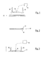
- Fig. 1 shows a film stack 10, which consists for example of films 12, as in Fig. 2 are shown.
- the foils 12 comprise a conductive electrode layer 14 on a base material 16.
- This may be, for example, an aluminum layer 14, which serves as an electrically conductive foil for a cathode, which is formed by the base material 16.
- a vacuum gripper with individual vacuum grippers 20 serves to receive individual sheets 12 of the stack 12.
- the vacuum gripper has an inductive film detector 30 which serves to detect the number of gripped sheets, as will be described below.
- the signal from the inductive film detector 30 is sent to an evaluation unit 40, which is designed to determine the number of films.
- the evaluation unit 40 can be used e.g. be connected to a programmable logic controller or include this. There, corresponding warnings or control signals can then be generated as a function of the signal of the evaluation unit.
- Fig. 3 shows the state in which the gripping device has received a film 12.
- the vacuum grippers 20 were lowered until they touch the uppermost sheet 12 of the stack 10.
- the resonant circuit provided in the inductive film detector is damped by the presence of the metallic coating of the film 12 in the manner described, so that the presence of a film can be detected.
- the inductive film detector 30 is a resonant circuit whose damping is measured in a conventional manner.
- the attenuation signal is evaluated by the evaluation device by being compared with a first threshold, the exceeding of which means the presence of only one film, whereas its falling below the presence of two films or the presence of no film means, if a very low threshold is fallen short of.
- a corresponding digital signal is output, which is e.g. processed in a PLC. This digital signal can therefore assume three values.
- Fig. 4 is shown how the damping can depend, for example, on the number of slides. If there is no film on the vacuum gripper, the damping signal is very low and the oscillating circuit oscillates almost undamped. If a film on the vacuum gripper, so a relatively high damping is observed. If there are two films on the gripper, the damping signal is again lower.
- Fig. 4 shows the damping in arbitrary units depending on the number of foils.
- the detection distance of the inductive film detector results in the application mentioned from the distance of the film sensor 30 of a gripped film 12 when it is on the vacuum gripper.
- the first and second threshold values are the same and only this one threshold value is checked. In this way it is possible to decide if a foil has been grasped. Whether two or no foil has been used is then indistinguishable.
- Fig. 5 shows by way of example and only for explanation, the layer structure of a rechargeable battery, which is explained here using the example of a lithium-ion battery.
- the cathode 16 ' serves to receive Li + ions and consists for example of LiFeMnPO4.
- On the cathode 16 ' is an electrode as an electrically conductive aluminum foil 14'.
- the anode 16 "comprises a material for discharging the Li + ions during discharging, for example, consisting of artificial graphite powder, and an electrically conductive copper foil 14" serves as the electrode.
- an electrolyte or separator 18 which is permeable to Li + ions but otherwise electrically insulating.
- the thicknesses of the metallic layers 14 'and 14 "in the example described are, for example, in the order of 20 to 30 .mu.m
- the cathodes or anode layers 16', 16" can be, for example, 20 to 40 .mu.m or even up to to be 200 microns thick.
- the inductive film detector according to the invention serves to determine the number of films 12 gripped by a stack 10, which consist of metallic layers 14 'or 14 "and the cathode or anode layers 16', 16".
Landscapes
- Chemical & Material Sciences (AREA)
- Chemical Kinetics & Catalysis (AREA)
- Electrochemistry (AREA)
- Life Sciences & Earth Sciences (AREA)
- Manufacturing & Machinery (AREA)
- General Chemical & Material Sciences (AREA)
- Physics & Mathematics (AREA)
- Health & Medical Sciences (AREA)
- Engineering & Computer Science (AREA)
- Analytical Chemistry (AREA)
- Biochemistry (AREA)
- General Health & Medical Sciences (AREA)
- General Physics & Mathematics (AREA)
- Immunology (AREA)
- Pathology (AREA)
- Measurement Of Length, Angles, Or The Like Using Electric Or Magnetic Means (AREA)
Abstract
Description
- Die Erfindung betrifft einen induktiven Foliendetektor zur Detektion der Anzahl von aneinander liegenden Folien, die jeweils ein Grundmaterial und eine daran angeordnete, elektrisch leitfähige Schicht umfassen. Die Erfindung betrifft weiterhin eine Greifeinrichtung für solche Folien von einem Stapel mit einem solchen induktiven Foliendetektor. Weiterhin betrifft die Erfindung ein Verfahren zur Bestimmung der Anzahl von solchen aneinander liegenden Folien.
- Zum Beispiel bei der Herstellung von Akkumulatoren werden beschichtete Folien als Anode und Kathode eingesetzt. Solche Folien werden in der Regel mit einem Vakuum-Greifer aus einem sortenreinen Stapel gehoben und auf einer Stapelposition in der Reihenfolge Anode, Separator, Kathode, Separator, Anode, Separator, Kathode, ... platziert. Dabei sollte immer genau eine Folie vom Stapel entnommen werden. Wenn es passiert, dass beim Greifen keine Folie gegriffen wird, oder gleich mehrere Folien (typischerweise z.B. zwei), die aneinander anhaften, wird eine undefinierte Situation in der Maschine herbeigeführt.
- Gerade bei automatisierten Fertigungslinien für Akkumulatoren ist dies im Hinblick auf die gewünschten größeren Mengen und geringen Kosten kritisch.
- Bekannte Anordnungen umfassen Vakuumgreifer mit biegsamer Greiferfläche. In einem ersten Schritt wird die oberste Folie mit dem Greifer von dem sortenreinen Stapel angesaugt und anschließend gebogen. Diese Biegung bewirkt, dass sich eine gegebenenfalls vorhandene zweite Folie von der ersten Folie lösen soll und nicht mit angehoben wird.
- Ob eine Folie abgegriffen worden ist, wird mit Hilfe eines Vakuumgrenzschalters an dem Vakuumgreifer detektiert. Eine sensorische Erkennung der Folien erfolgt mit analogen induktiven Sensoren. Ob tatsächlich nur eine Folie aufgegriffen worden ist, muss daher beim Stand der Technik unter Einsatz einer gegebenenfalls teuren Analogkarte anhand eines analogen Messsignals erfolgen.
- Es sind induktive Näherungssensoren bekannt, mit deren Hilfe der Abstand eines Objekts von dem Sensor aus der Bedämpfung des Schwingkreises durch das Objekt bestimmt wird. Eine Aussage über die Anzahl von einzelnen Folien ist dabei nicht vorgesehen.
- Aufgabe der vorliegenden Erfindung ist es, einen induktiven Foliendetektor anzugeben, mit dem eine einfache und kostengünstige Auswertung und Weiterverarbeitung der Information möglich ist, insbesondere auch unter Einsatz einer speicherprogrammierbaren Steuerung (SPS).
- Diese Aufgabe wird mit einem induktiven Foliendetektor mit den Merkmalen des Anspruchs 1, einer Greifeinrichtung mit den Merkmalen des Anspruchs 4 und einem Verfahren zur Bestimmung der Anzahl von aneinander liegenden Folien mit den Merkmalen des Anspruchs 5 gelöst. Unteransprüche sind auf bevorzugte Ausgestaltungen gerichtet.
- Ein erfindungsgemäßer induktiver Foliendetektor dient zur Detektion der Anzahl von aneinander liegenden Folien, die jeweils ein, insbesondere schlecht leitendes oder isolierendes, Grundmaterial und eine daran angeordnete elektrisch leitfähige Schicht umfassen. Insbesondere kann es sich dabei z.B. um Anoden- und/oder Kathodenfolien zum Einsatz in Akkumulatoren handeln. Dabei bestehen die Folien beispielsweise aus Kupfer bzw. Aluminiumschichten auf schlecht leitendem oder isolierendem Anoden- bzw. Kathodenmaterial.
- Der erfindungsgemäße induktive Foliendetektor weist einen Schwingkreis zur Erzeugung eines elektromagnetischen Wechselfeldes auf. Befindet sich in diesem von dem Schwingkreis erzeugten elektromagnetischen Wechselfeld eine Folie mit einer metallischen Schicht, so wird in dieser Folie durch das elektromagnetische Wechselfeld des Schwingkreises ein Wirbelstrom angeregt, der wiederum ein dem anregenden elektromagnetischen Wechselfeld des Schwingkreises entgegengesetztes Feld bewirkt. Der Schwingkreis wird dementsprechend durch die Anwesenheit der Folie bedämpft. Diese Bedämpfung kann in an sich bekannter Weise wie z.B. bei einem induktiven Näherungssensor bestimmt werden. Die Erfinder haben erkannt, dass z.B. aufgrund der geringen Materialstärke der Metallschicht beziehungsweise einer schlecht leitenden oder isolierenden Grundmaterialschicht, wie sie beispielsweise bei Akkumulatorfolien zum Einsatz kommen, das elektromagnetische Wechselfeld des induktiven Detektors eine Folie durchdringen kann und eine gegebenenfalls vorhandene zweite Folie erfassen kann. Das elektromagnetische Wechselfeld, das die erste Folie durchdringt, kann - geschwächt durch das von dem Wirbelstrom in der ersten Folie angeregten Magnetfeld - auf die zweite Folie wirken und dort ebenfalls einen Wirbelstrom erzeugen, der wiederum zu einem elektromagnetischen Gegenfeld führt. Bei Vorhandensein einer Folie ist die Bedämpfung daher größer als bei einer größeren Anzahl Folien. Erfindungsgemäß ist dazu eine Auswerteeinrichtung vorgesehen, mit der die Bedämpfung des Schwingkreises bestimmt werden kann, wobei die Auswerteeinrichtung derart ausgestaltet ist, dass sie bei Überschreiten eines ersten vorgegebenen Schwellwertes der Bedämpfung vom Vorhandensein einer einzelnen Folie in einem vorgegebenen Detektionsabstand ausgeht und ein entsprechendes Signal erzeugt, bei Unterschreiten des ersten Schwellwertes vom Vorhandensein zweier oder mehr Folien im vorgegebenen Detektionsabstand ausgeht und ein entsprechendes Signal erzeugt und bei Unterschreiten eines zweiten vorgegebenen Schwellwertes, der kleiner als der erste Schwellwert ist, von einem Zustand ohne Folien im Detektionsabstand ausgeht und ein entsprechendes Signal erzeugt. Dabei kann der Detektionsabstand insbesondere z.B. dem Abstand entsprechen, der sich ergibt, wenn die Folie von einem Vakuumgreifer gehalten wird, an dem der erfindungsgemäße induktive Foliendetektor befestigt ist.
- Grundsätzlich ist es auch möglich, dass der erste und der zweite Schwellwert gleich sind. Auf diese Weise kann durch Vergleich des Bedämpfungssignals mit dem Schwellwert festgestellt werden, ob dieser überschritten ist und insofern vom Vorliegen genau eines Foliendetektionsabstands ausgegangen werden muss. Bei Unterschreiten des Schwellwertes liegen entweder zwei Folien oder keine Folie vor, weil das Bedämpfungssignal in beiden Fällen kleiner ist als das Bedämpfungssignal beim Vorhandensein von nur einer Folie. Trotzdem kann aus dem Über- bzw. Unterschreiten des Schwellwerts entschieden werden, ob ein gewünschter (genau eine Folie) oder ein nicht gewünschter (keine oder zwei oder mehr Folien) vorliegt, um entsprechende Maßnahmen im Prozess zu ergreifen.
- Insbesondere eignet sich der erfindungsgemäße induktive Foliendetektor für Anoden- und/oder Kathodenfolien zum Einsatz in Akkumulatoren. In der Regel weisen diese eine wenige Mikrometer dicke Metallschicht (z.B. 10 bis 30 µm) auf, die sich auf einem ebenfalls wenige Mikrometer dicken Grundmaterial (z.B. 100 bis 200 µm Dicke) befindet. Es können aber auch andere Materialstärken vorliegen, solange der oben beschriebene Effekt der kleineren Bedämpfung des Schwingkreises bei größerer Folienanzahl erhalten bleibt. Das Grundmaterial ist zum Beispiel schlecht leitend oder isolierend, wie es bei Akkumulatorfolien der Fall ist.
- Eine Kathodenfolie besteht dabei z.B. aus einer Aluminiumschicht auf einer Kathodenschicht. Eine solche Kathodenschicht kann (bei einem Li-lonen-Akku) z.B. aus LiFeMnPO4 zur Aufnahme von Li+-Ionen beim Entladevorgang bestehen. Eine Anodenfolie kann z.B. aus einer Kupferschicht auf einer Anodenschicht bestehen. Eine solche Anodenschicht kann dabei bei einem Li-Ionen-Akku z.B. aus künstlichem Graphitpulver zur Abgabe der Li+-Ionen beim Entladen dienen.
- Zwischen Anodenfolie und Kathodenfolie befindet sich bei einem Akkumulator ein Elektrolyt bzw. Separator, der beim geschilderten Beispiel durchlässig für Li+-Ionen, aber elektrisch isolierend ist.
- Gemäß einer besonders vorteilhaften Ausgestaltung ist die Auswerteeinrichtung derart ausgestaltet, dass sie ein Signal an einem Digitalausgang gibt, dessen Größe vom Über- bzw. Unterschreiten des ersten und/oder des zweiten Stellwertes abhängt. Ein solches digitales Ausgangssignal kann auf vorteilhafte und einfache Weise aus dem erfindungsgemäß stattfindenden Vergleich der Bedämpfung des Schwingkreises mit dem ersten bzw. dem zweiten Schwellwert erzeugt werden. In einem Hauptanwendungsfall, in dem festgestellt werden soll, ob eine, zwei oder keine Folie mit Hilfe eines Vakuumgreifers gehalten werden, kann z.B. ein Digitalausgang der Auswerteeinrichtung so ausgestaltet sein, dass drei unterschiedliche digitale Signale ausgegeben werden können, die dem Vorhandensein von keiner, einer bzw. zwei Folien entsprechen.
- Ein solches Signal lässt sich besonders einfach durch eine speicherprogrammierbare Steuerung (SPS) verarbeiten. Mit der SPS kann dann z.B. eine Anzeige, ein Warnsignal oder ein Aktorsignal getriggert werden, das eine Anlage stoppt oder umlenkt, wenn weniger als eine oder mehr als eine Folie gegriffen worden sind.
- Der induktive Foliendetektor kann eine Speichereinrichtung aufweisen, in der die relevanten Schwellwerte abgelegt sind. Dabei kann entweder genau ein Szenario durch entsprechende vorgegebene Schwellwerte behandelt werden (also z.B. in einer Anlage, in der immer dieselben Folien zum Einsatz kommen), wobei diese Schwellwerte in Abhängigkeit dieser Folien zuvor eingelernt werden. Bei anderen Ausgestaltungen des erfindungsgemäßen Foliendetektors kann auch eine Speichereinrichtung vorgesehen sein, in der mehrere unterschiedliche Folienmaterialien und die daraus resultierenden Schwellwerte abgelegt sind, die z.B. ebenfalls im Vorhinein für die unterschiedlichen Folien eingelernt worden sind. Bei einer solchen Ausgestaltung kann dann z.B. an einem entsprechenden Auswahlmenü eingestellt werden, welche Folien gerade verarbeitet werden.
- Bei einem erfindungsgemäßen Verfahren kann ein erfindungsgemäßer induktiver Foliensensor zum Einsatz kommen. Eine unbekannte Folienanzahl wird in einen Detektionsabstand gebracht. Mit einem Schwingkreis wird ein elektromagnetisches Wechselfeld erzeugt und aus der Bedämpfung des Schwingkreises auf die Anzahl von Folien in dem vorgegebenen Detektionsabstand geschlossen, wobei bei einer größeren Bedämpfung von einer kleineren Anzahl Folien ausgegangen wird.
- Nur bei einer minimalen Bedämpfung wird davon ausgegangen, dass keine Folie im Detektionsabstand vorhanden ist.
- Die unbekannte Anzahl an Folien, die in den Detektionsabstand gebracht wird, ergibt sich z.B. dadurch, wie viele Folien ein Vakuumgreifer auf einmal greift. Idealerweise ist dies nur eine Folie, die auf den Stapel des zukünftigen Akkumulators gelegt werden soll. Wird keine oder werden zwei Folien gegriffen, so ist dies mit dem erfindungsgemäßen Verfahren feststellbar und es können die entsprechenden Maßnahmen ergriffen werden, dass kein fehlerhafter Aufbau des Akkumulators erfolgt.
- Vorteilhafterweise wird dabei abgeprüft, ob sich die Bedämpfung des Schwingkreises oberhalb eines ersten Schwellwertes befindet und insofern davon ausgegangen wird, dass eine einzelne Folie vorhanden ist, oder ob ein zweiter Schwellwert unterschritten wird, so dass davon ausgegangen wird, dass keine Folie vorhanden ist, oder beim Unterschreiten des ersten Schwellwertes bzw. Überschreiten des zweiten Schwellwertes davon ausgegangen wird, dass zwei oder mehr Folien vorhanden sind.
- Weitere Vorteile und Ausgestaltungen des erfindungsgemäßen Verfahrens ergeben sich aus der obigen Beschreibung der Vorteile und Ausgestaltungen des erfindungsgemäßen induktiven Foliensensors.
- Sowohl der erfindungsgemäße induktive Foliendetektor als auch das erfindungsgemäße Verfahren können so ausgestaltet sein, dass auch andere Anzahlen als Null, eine oder zwei Folien erkannt werden können, wenn eine entsprechende Anzahl von Schwellwerten abgespeichert bzw. abgeprüft wird.
- Die Erfindung wird anhand der beiliegenden Figuren im Detail erläutert. Dabei zeigen in schematischer Darstellung:
- Fig. 1
- die Anordnung eines Vakuumgreifers oberhalb eines Folienstapels mit einem induktiven Foliendetektor,
- Fig. 2
- eine schematische Darstellung einer zu greifenden Folie,
- Fig.3
- die Anordnung der
Fig. 1 während des Aufnehmens einer Folie, - Fig. 4
- ein Bedämpfungssignal in Abhängigkeit der Anzahl der aufgenommenen Folien, und
- Fig. 5
- ein Detail einer Akkumulatoranordnung, die mit einem Vakuumgreifer der
Fig. 1 bzw. 3 unter Einsatz eines erfindungsgemäßen induktiven Foliendetektors aufgebaut werden kann. -
Fig. 1 zeigt einen Folienstapel 10, der z.B. aus Folien 12 besteht, wie sie inFig. 2 gezeigt sind. Die Folien 12 umfassen eine leitfähige Elektrodenschicht 14 auf einem Grundmaterial 16. Es kann sich dabei z.B. um eine Aluminiumschicht 14 handeln, die als elektrisch leitende Folie für eine Kathode dient, die durch das Grundmaterial 16 gebildet wird. - Eine Vakuumgreifeinrichtung mit einzelnen Vakuumgreifern 20 dient zur Aufnahme von einzelnen Folien 12 des Stapels 12. Die Vakuumgreifeinrichtung weist einen induktiven Foliendetektor 30 auf, der zur Detektion der Anzahl von gegriffenen Folien dient, wie es weiter unten beschrieben werden wird. Das Signal des induktiven Foliendetektors 30 wird an eine Auswerteeinheit 40 gegeben, die ausgestaltet ist, die Anzahl der Folien zu bestimmen. In nicht gezeigter Weise kann die Auswerteeinheit 40 z.B. mit einer speicherprogrammierbaren Steuerung verbunden sein oder diese umfassen. Dort können dann in Abhängigkeit des Signales der Auswerteeinheit entsprechende Warnungen oder Steuerungssignale erzeugt werden.
-
Fig. 3 zeigt den Zustand, in dem die Greifeinrichtung eine Folie 12 aufgenommen hat. Dazu wurden die Vakuumgreifer 20 abgesenkt, bis sie die oberste Folie 12 des Stapels 10 berühren. Durch Anlegen von Vakuum wird im Idealfall einer einzelnen Folie 12 abgehoben. Der in dem induktiven Foliendetektor vorgesehene Schwingkreis wird durch die Anwesenheit der metallischen Beschichtung der Folie 12 in beschriebener Weise bedämpft, so dass die Anwesenheit einer Folie detektiert werden kann. - Grundsätzlich kann es aber auch passieren, dass z.B. zwei Folien aneinanderhaften, so dass zwei Folien 12 gleichzeitig aufgegriffen werden. Das Bedämpfungssignal des Schwingkreises ist dann anders, als wenn nur eine Folie vorliegt. Insbesondere ist das Bedämpfungssignal beim Vorhandensein von zwei Folien geringer als von nur einer Folie.
- In dem induktiven Foliendetektor 30 befindet sich ein Schwingkreis, dessen Bedämpfung in an sich bekannter Weise gemessen wird. Das Bedämpfungssignal wird von der Auswerteeinrichtung ausgewertet, indem es mit einem ersten Schwellwert verglichen wird, dessen Überschreiten die Präsenz von nur einer Folie bedeutet, wohingegen dessen Unterschreiten die Präsenz von zwei Folien bzw. die Präsenz von gar keiner Folie bedeutet, wenn ein sehr geringer Schwellwert unterschritten wird. Am Ausgang der Auswerteeinrichtung 40 wird ein entsprechendes digitales Signal ausgegeben, das z.B. in einer SPS weiterverarbeitet wird. Dieses digitale Signal kann also drei Werte annehmen.
- In
Fig. 4 ist dargestellt, wie die Bedämpfung beispielsweise von der Folienanzahl abhängen kann. Ist keine Folie am Vakuumgreifer, so ist das Bedämpfungssignal sehr gering und der Schwingkreis schwingt nahezu ungedämpft. Ist eine Folie am Vakuumgreifer, so ist eine relativ hohe Bedämpfung festzustellen. Sind zwei Folien am Greifer, so ist das Bedämpfungssignal wiederum geringer. -
Fig. 4 zeigt die Bedämpfung in beliebigen Einheiten in Abhängigkeit der Folienanzahl. Der Detektionsabstand des induktiven Foliendetektors ergibt sich bei der genannten Anwendung aus dem Abstand des Foliensensors 30 von einer gegriffenen Folie 12, wenn sie sich am Vakuumgreifer befindet. - Grundsätzlich ist es auch möglich, dass der erste und der zweite Schwellwert gleich sind und nur dieser eine Schwellwert abgeprüft wird. Auf diese Weise ist es möglich, zu entscheiden, ob eine Folie gegriffen worden ist. Ob zwei oder gar keine Folie gegriffen worden sind, ist dann nicht zu unterscheiden.
-
Fig. 5 zeigt beispielhaft und nur zur Erläuterung den Lagenaufbau eines Akkumulators, der hier anhand des Beispiels eines Lithium-Ionen-Akkus erläutert wird. Die Kathode 16' dient zur Aufnahme von Li+-Ionen und besteht z.B. aus LiFeMnPO4. Auf der Kathode 16' befindet sich als Elektrode eine elektrisch leitende Aluminium-folie 14'. Andererseits umfasst die Anode 16" ein Material zur Abgabe der Li+-Ionen beim Entladen. Es besteht z.B. aus künstlichem Graphitpulver. Als Elektrode dient eine elektrisch leitende Kupferfolie 14". Zwischen Anode und Kathode befindet sich ein Elektrolyt bzw. Separator 18, der für Li+-Ionen durchlässig aber ansonsten elektrisch isolierend ist. Die Dicken der metallischen Schichten 14' bzw. 14" betragen bei dem beschriebenen Beispiel z.B. in der Größenordnung von 20 bis 30 µm. Die Kathoden bzw. Anodenschichten 16', 16" können je nach Anwendung und Ausgestaltung z.B. 20 bis 40 µm oder auch bis zu 200 µm dick sein. - Der erfindungsgemäße induktive Foliendetektor dient dazu, die Anzahl von von einem Stapel 10 gegriffenen Folien 12 zu bestimmen, die aus metallischen Schichten 14' bzw. 14" und den Kathoden- bzw. Anodenschichten 16', 16" bestehen.
-
- 10
- Folienstapel
- 12
- Folie
- 14
- elektrisch leitfähige Schicht
- 16
- Grundmaterial
- 12'
- Kathodenfolie
- 12"
- Anodenfolie
- 14'
- Aluminiumschicht
- 14"
- Kupferschicht
- 16'
- Kathodenschicht
- 16"
- Anodenschicht
- 18
- Separator, Elektrolyt
- 20
- Greifer
- 30
- induktiver Foliendetektor
- 40
- Auswerteeinrichtung
- SW1
- erster Schwellwert
- SW2
- zweiter Schwellwert
Claims (9)
- Induktiver Foliendetektor (30) zur Detektion der Anzahl von aneinander liegenden Folien (12), die jeweils ein insbesondere nicht oder schlecht leitendes Grundmaterial (16) und eine daran angeordnete, elektrisch leitfähige Schicht (14) umfassen, mit- einem Schwingkreis zur Erzeugung eines elektromagnetischen Wechselfeldes, und- einer Auswerteeinrichtung (40) zur Bestimmung der Bedämpfung des Schwingkreises, wobei entweder(i) die Auswerteeinrichtung (40) derart ausgestaltet ist, dass sie bei Überschreiten eines ersten vorgegebenen Schwellwertes (SW1) der Bedämpfung vom Vorhandensein einer einzelnen Folie (12) in einem vorgegebenen Detektionsabstand, bei Unterschreiten des ersten Schwellwertes (SW1) vom Vorhandensein wenigstens zweier Folien (12) im vorgegebenen Detektionsabstand und bei Unterschreiten eines zweiten vorgegebenen Schwellwertes (SW2), der kleiner als der erste Schwellwert (SW1) ist, von einem Zustand ohne Folie im Detektionsabstand ausgeht, oder(ii) der zweite Schwellwert gleich dem ersten Schwellwert ist und die Auswerteeinheit (40) derart ausgestaltet ist, dass sie bei Überschreiten des Schwellwertes vom Vorhandensein genau einer Folie (12) im Detektionsabstand und beim Unterschreiten des Schwellwertes vom Vorliegen gar keiner oder von zwei oder mehr Folien (12) im Detektionsabstand ausgeht.
- Induktiver Foliendetektor nach Anspruch 1, bei dem die Auswerteeinrichtung (40) derart ausgestaltet ist, dass sie ein Signal an einen Digitalausgang gibt, dessen Größe vom Über- bzw. Unterschreiten des ersten und/oder des zweiten Schwellwertes (SW1, SW2) abhängt.
- Induktiver Foliendetektor nach einem der Ansprüche 1 oder 2, mit einer Speichereinrichtung, in dem eingelernte Schwellwerte (SW1, SW2) abgelegt sind, die in Abhängigkeit der zu detektierenden Folien (12) in einem Teach-In-Prozess bestimmt wurden.
- Greifeinrichtung (20) für Folien (12) von einem Stapel (10), insbesondere von Anoden- und/oder Kathodenfolien (12', 12") zum Einsatz in Akkumulatoren, mit einem induktiven Foliendetektor (30) nach einem der Ansprüche 1 bis 3, der derart an der Greifeinrichtung (20) angeordnet ist, dass er die Anzahl der von dem Greifer gehaltenen Folien (12) bestimmen kann.
- Verfahren zur Bestimmung der Anzahl von aneinander liegenden Folien (12) in einem Detektionsabstand, die jeweils ein Grundmaterial (16) und eine daran angeordnete, elektrisch leitfähige Schicht (14) umfassen, insbesondere von Anoden- und/oder Kathodenfolien (12', 12") zum Einsatz in Akkumulatoren, bei dem die unbekannte Folienanzahl in einen Detektionsabstand gebracht wird, mit einem Schwingkreis ein elektromagnetisches Wechselfeld erzeugt wird und aus der Bedämpfung des Schwingkreises auf die Anzahl von Folien (12) in dem vorgegebenen Detektionsabstand geschlossen wird, wobei bei einer größeren Bedämpfung von einer kleineren Anzahl Folien (12) ausgegangen wird.
- Verfahren nach Anspruch 5, bei dem bei Überschreiten eines ersten vorgegebenen Schwellwertes (SW1) der Bedämpfung vom Vorhandensein genau einer Folie (12) in einem vorgegebenen Detektionsabstand ausgegangen wird.
- Verfahren nach Anspruch 6, bei dem bei Unterschreiten des ersten Schwellwertes (SW1) vom Vorhandensein wenigstens zweier Folien (12) im vorgegebenen Detektionsabstand und bei Unterschreiten eines zweiten vorgegebenen Schwellwertes (SW2), der kleiner als der erste Schwellwert (SW1) ist, von einem Zustand ohne Folie im Detektionsabstand ausgegangen wird.
- Verfahren nach Anspruch 6, bei dem beim Unterschreiten des ersten Schwellwerts vom Vorliegen gar keiner oder von zwei oder mehr Folien (12) im Detektionsabstand ausgegangen wird.
- Verfahren nach einem der Ansprüche 5 bis 8, bei dem der Schwellwert oder die Schwellwerte im Vorhinein eingelernt wird/werden.
Applications Claiming Priority (1)
| Application Number | Priority Date | Filing Date | Title |
|---|---|---|---|
| DE102014103670.0A DE102014103670A1 (de) | 2014-03-18 | 2014-03-18 | Induktiver Foliendetektor |
Publications (2)
| Publication Number | Publication Date |
|---|---|
| EP2921853A1 true EP2921853A1 (de) | 2015-09-23 |
| EP2921853B1 EP2921853B1 (de) | 2016-09-28 |
Family
ID=52824006
Family Applications (1)
| Application Number | Title | Priority Date | Filing Date |
|---|---|---|---|
| EP15158624.5A Active EP2921853B1 (de) | 2014-03-18 | 2015-03-11 | Induktiver foliendetektor |
Country Status (2)
| Country | Link |
|---|---|
| EP (1) | EP2921853B1 (de) |
| DE (1) | DE102014103670A1 (de) |
Families Citing this family (1)
| Publication number | Priority date | Publication date | Assignee | Title |
|---|---|---|---|---|
| DE102016213223A1 (de) * | 2016-07-20 | 2018-01-25 | Robert Bosch Gmbh | Verfahren zur Herstellung einer Elektrodeneinheit für eine Batteriezelle und Elektrodeneinheit |
Citations (4)
| Publication number | Priority date | Publication date | Assignee | Title |
|---|---|---|---|---|
| EP0125386A2 (de) * | 1983-04-15 | 1984-11-21 | International Business Machines Corporation | Druckbandpositionsgeber |
| US6437560B1 (en) * | 2000-10-31 | 2002-08-20 | Syron Engineering & Manufacturing, Llc | Combined suction cup and isolated sensor |
| EP1959570A2 (de) * | 2007-02-15 | 2008-08-20 | Sick Ag | Induktiver Nährungssensor |
| US20130064635A1 (en) * | 2010-05-12 | 2013-03-14 | Senstronic (Societe Par Actions Simplifiee) | Device for detecting and counting metal elements |
-
2014
- 2014-03-18 DE DE102014103670.0A patent/DE102014103670A1/de not_active Withdrawn
-
2015
- 2015-03-11 EP EP15158624.5A patent/EP2921853B1/de active Active
Patent Citations (4)
| Publication number | Priority date | Publication date | Assignee | Title |
|---|---|---|---|---|
| EP0125386A2 (de) * | 1983-04-15 | 1984-11-21 | International Business Machines Corporation | Druckbandpositionsgeber |
| US6437560B1 (en) * | 2000-10-31 | 2002-08-20 | Syron Engineering & Manufacturing, Llc | Combined suction cup and isolated sensor |
| EP1959570A2 (de) * | 2007-02-15 | 2008-08-20 | Sick Ag | Induktiver Nährungssensor |
| US20130064635A1 (en) * | 2010-05-12 | 2013-03-14 | Senstronic (Societe Par Actions Simplifiee) | Device for detecting and counting metal elements |
Also Published As
| Publication number | Publication date |
|---|---|
| DE102014103670A1 (de) | 2015-09-24 |
| EP2921853B1 (de) | 2016-09-28 |
Similar Documents
| Publication | Publication Date | Title |
|---|---|---|
| EP2976818B1 (de) | Einrichtung zur erkennung der berührung eines elektrischen leiters durch ein werkzeug | |
| EP3194831B1 (de) | Kapazitiver sensor | |
| DE102017221248B4 (de) | Verfahren zur Bestimmung eines aktuellen Ladezustandswerts einer Batterie, Batterieanordnung und Kraftfahrzeug | |
| DE102014016422A1 (de) | Vorrichtung und Verfahren zur Erfassung einer Lenkradberührung | |
| DE102013219131B4 (de) | Vorrichtung und Verfahren zur Erkennung eines Fremdkörpers in einem zur leitungslosen Energieübertragung vorgesehenen Magnetfeld | |
| WO2015180942A1 (de) | Sensoreinrichtung für ein kraftfahrzeug | |
| DE102013007011A1 (de) | Verfahren zum Laden einer Lithium-lonen-Batterie sowie System mit einer Lithium-lonen-Batterie und einem Batteriemanagementsystem | |
| DE102011054415A1 (de) | Verfahren zum Anpassen der Sensitivität eines Sensorsystems | |
| EP4182991B1 (de) | Akkupack mit pouchzelle und verfahren | |
| EP2921853B1 (de) | Induktiver foliendetektor | |
| DE102016206980A1 (de) | Verfahren zur Handhabung eines Körpers und Handhabungsvorrichtung | |
| EP3153282B1 (de) | Greifvorrichtung und betriebsverfahren für eine greifvorrichtung | |
| DE202014101230U1 (de) | Induktiver Foliendetektor | |
| DE102020108382B4 (de) | System für eine Kabelstrecke, Übertragungssystem zum Übertragen von elektrischer Energie und Verfahren zum Betrieb des Systems | |
| DE102014221392A1 (de) | Vorrichtung, Messanordnung und Verfahren zur Überprüfung des Funktionszustandes einer elektrisch isolierenden Schutzhülle von einer Batterie | |
| DE102022105284B4 (de) | Maschinelle Handhabungsvorrichtung und Verfahren zum Handhaben eines elektrisch leitfähigen Blechwerkstücks sowie maschinelle Anordnung für die Blechbearbeitung | |
| EP3377801B1 (de) | Anordnung mit zumindest einer schussquelle und zumindest einer detektorvorrichtung | |
| EP3394983B1 (de) | Verfahren zum betreiben eines sensorsystems, sensorelement sowie sensorsystem | |
| DE202012100255U1 (de) | Hebevorrichtung mit einem Vakuumheber | |
| DE19537059A1 (de) | Anordnung zum berührungslosen Messen der spezifischen Leitfähigkeit wäßriger Lösungen | |
| EP2652817A1 (de) | Verfahren und system zur herstellung von blatt- oder plattenförmigen objekten | |
| EP1944568A2 (de) | Anordnung zur Messung der Position eines Magneten relativ zu einem Magnetkern | |
| EP4084939B1 (de) | Sensorvorrichtung, greifvorrichtung, verfahren und steuereinheit für eine greifvorrichtung | |
| WO2017005809A1 (de) | Vorrichtung und verfahren zur reversiblen kontaktierung | |
| DE102013001214A1 (de) | Verfahren zum Vereinzeln von Schüttgut |
Legal Events
| Date | Code | Title | Description |
|---|---|---|---|
| PUAI | Public reference made under article 153(3) epc to a published international application that has entered the european phase |
Free format text: ORIGINAL CODE: 0009012 |
|
| AK | Designated contracting states |
Kind code of ref document: A1 Designated state(s): AL AT BE BG CH CY CZ DE DK EE ES FI FR GB GR HR HU IE IS IT LI LT LU LV MC MK MT NL NO PL PT RO RS SE SI SK SM TR |
|
| AX | Request for extension of the european patent |
Extension state: BA ME |
|
| RIN1 | Information on inventor provided before grant (corrected) |
Inventor name: HALL, THOMAS Inventor name: DORER, ARMIN Inventor name: WEGNER, BOERGE |
|
| 17P | Request for examination filed |
Effective date: 20160316 |
|
| RBV | Designated contracting states (corrected) |
Designated state(s): AL AT BE BG CH CY CZ DE DK EE ES FI FR GB GR HR HU IE IS IT LI LT LU LV MC MK MT NL NO PL PT RO RS SE SI SK SM TR |
|
| GRAP | Despatch of communication of intention to grant a patent |
Free format text: ORIGINAL CODE: EPIDOSNIGR1 |
|
| RIC1 | Information provided on ipc code assigned before grant |
Ipc: G01N 27/90 20060101AFI20160511BHEP Ipc: H03K 17/95 20060101ALI20160511BHEP |
|
| INTG | Intention to grant announced |
Effective date: 20160602 |
|
| GRAS | Grant fee paid |
Free format text: ORIGINAL CODE: EPIDOSNIGR3 |
|
| GRAA | (expected) grant |
Free format text: ORIGINAL CODE: 0009210 |
|
| AK | Designated contracting states |
Kind code of ref document: B1 Designated state(s): AL AT BE BG CH CY CZ DE DK EE ES FI FR GB GR HR HU IE IS IT LI LT LU LV MC MK MT NL NO PL PT RO RS SE SI SK SM TR |
|
| REG | Reference to a national code |
Ref country code: GB Ref legal event code: FG4D Free format text: NOT ENGLISH |
|
| REG | Reference to a national code |
Ref country code: CH Ref legal event code: EP |
|
| REG | Reference to a national code |
Ref country code: AT Ref legal event code: REF Ref document number: 833194 Country of ref document: AT Kind code of ref document: T Effective date: 20161015 |
|
| REG | Reference to a national code |
Ref country code: IE Ref legal event code: FG4D Free format text: LANGUAGE OF EP DOCUMENT: GERMAN |
|
| REG | Reference to a national code |
Ref country code: DE Ref legal event code: R096 Ref document number: 502015000187 Country of ref document: DE |
|
| REG | Reference to a national code |
Ref country code: LT Ref legal event code: MG4D |
|
| PG25 | Lapsed in a contracting state [announced via postgrant information from national office to epo] |
Ref country code: FI Free format text: LAPSE BECAUSE OF FAILURE TO SUBMIT A TRANSLATION OF THE DESCRIPTION OR TO PAY THE FEE WITHIN THE PRESCRIBED TIME-LIMIT Effective date: 20160928 Ref country code: RS Free format text: LAPSE BECAUSE OF FAILURE TO SUBMIT A TRANSLATION OF THE DESCRIPTION OR TO PAY THE FEE WITHIN THE PRESCRIBED TIME-LIMIT Effective date: 20160928 Ref country code: HR Free format text: LAPSE BECAUSE OF FAILURE TO SUBMIT A TRANSLATION OF THE DESCRIPTION OR TO PAY THE FEE WITHIN THE PRESCRIBED TIME-LIMIT Effective date: 20160928 Ref country code: LT Free format text: LAPSE BECAUSE OF FAILURE TO SUBMIT A TRANSLATION OF THE DESCRIPTION OR TO PAY THE FEE WITHIN THE PRESCRIBED TIME-LIMIT Effective date: 20160928 Ref country code: NO Free format text: LAPSE BECAUSE OF FAILURE TO SUBMIT A TRANSLATION OF THE DESCRIPTION OR TO PAY THE FEE WITHIN THE PRESCRIBED TIME-LIMIT Effective date: 20161228 |
|
| REG | Reference to a national code |
Ref country code: NL Ref legal event code: MP Effective date: 20160928 |
|
| PG25 | Lapsed in a contracting state [announced via postgrant information from national office to epo] |
Ref country code: GR Free format text: LAPSE BECAUSE OF FAILURE TO SUBMIT A TRANSLATION OF THE DESCRIPTION OR TO PAY THE FEE WITHIN THE PRESCRIBED TIME-LIMIT Effective date: 20161229 Ref country code: NL Free format text: LAPSE BECAUSE OF FAILURE TO SUBMIT A TRANSLATION OF THE DESCRIPTION OR TO PAY THE FEE WITHIN THE PRESCRIBED TIME-LIMIT Effective date: 20160928 Ref country code: SE Free format text: LAPSE BECAUSE OF FAILURE TO SUBMIT A TRANSLATION OF THE DESCRIPTION OR TO PAY THE FEE WITHIN THE PRESCRIBED TIME-LIMIT Effective date: 20160928 Ref country code: LV Free format text: LAPSE BECAUSE OF FAILURE TO SUBMIT A TRANSLATION OF THE DESCRIPTION OR TO PAY THE FEE WITHIN THE PRESCRIBED TIME-LIMIT Effective date: 20160928 |
|
| PG25 | Lapsed in a contracting state [announced via postgrant information from national office to epo] |
Ref country code: RO Free format text: LAPSE BECAUSE OF FAILURE TO SUBMIT A TRANSLATION OF THE DESCRIPTION OR TO PAY THE FEE WITHIN THE PRESCRIBED TIME-LIMIT Effective date: 20160928 Ref country code: EE Free format text: LAPSE BECAUSE OF FAILURE TO SUBMIT A TRANSLATION OF THE DESCRIPTION OR TO PAY THE FEE WITHIN THE PRESCRIBED TIME-LIMIT Effective date: 20160928 |
|
| PG25 | Lapsed in a contracting state [announced via postgrant information from national office to epo] |
Ref country code: BG Free format text: LAPSE BECAUSE OF FAILURE TO SUBMIT A TRANSLATION OF THE DESCRIPTION OR TO PAY THE FEE WITHIN THE PRESCRIBED TIME-LIMIT Effective date: 20161228 Ref country code: SK Free format text: LAPSE BECAUSE OF FAILURE TO SUBMIT A TRANSLATION OF THE DESCRIPTION OR TO PAY THE FEE WITHIN THE PRESCRIBED TIME-LIMIT Effective date: 20160928 Ref country code: ES Free format text: LAPSE BECAUSE OF FAILURE TO SUBMIT A TRANSLATION OF THE DESCRIPTION OR TO PAY THE FEE WITHIN THE PRESCRIBED TIME-LIMIT Effective date: 20160928 Ref country code: SM Free format text: LAPSE BECAUSE OF FAILURE TO SUBMIT A TRANSLATION OF THE DESCRIPTION OR TO PAY THE FEE WITHIN THE PRESCRIBED TIME-LIMIT Effective date: 20160928 Ref country code: PT Free format text: LAPSE BECAUSE OF FAILURE TO SUBMIT A TRANSLATION OF THE DESCRIPTION OR TO PAY THE FEE WITHIN THE PRESCRIBED TIME-LIMIT Effective date: 20170130 Ref country code: PL Free format text: LAPSE BECAUSE OF FAILURE TO SUBMIT A TRANSLATION OF THE DESCRIPTION OR TO PAY THE FEE WITHIN THE PRESCRIBED TIME-LIMIT Effective date: 20160928 Ref country code: IS Free format text: LAPSE BECAUSE OF FAILURE TO SUBMIT A TRANSLATION OF THE DESCRIPTION OR TO PAY THE FEE WITHIN THE PRESCRIBED TIME-LIMIT Effective date: 20170128 Ref country code: CZ Free format text: LAPSE BECAUSE OF FAILURE TO SUBMIT A TRANSLATION OF THE DESCRIPTION OR TO PAY THE FEE WITHIN THE PRESCRIBED TIME-LIMIT Effective date: 20160928 |
|
| REG | Reference to a national code |
Ref country code: DE Ref legal event code: R097 Ref document number: 502015000187 Country of ref document: DE |
|
| PG25 | Lapsed in a contracting state [announced via postgrant information from national office to epo] |
Ref country code: IT Free format text: LAPSE BECAUSE OF FAILURE TO SUBMIT A TRANSLATION OF THE DESCRIPTION OR TO PAY THE FEE WITHIN THE PRESCRIBED TIME-LIMIT Effective date: 20160928 |
|
| PG25 | Lapsed in a contracting state [announced via postgrant information from national office to epo] |
Ref country code: DK Free format text: LAPSE BECAUSE OF FAILURE TO SUBMIT A TRANSLATION OF THE DESCRIPTION OR TO PAY THE FEE WITHIN THE PRESCRIBED TIME-LIMIT Effective date: 20160928 |
|
| PLBE | No opposition filed within time limit |
Free format text: ORIGINAL CODE: 0009261 |
|
| STAA | Information on the status of an ep patent application or granted ep patent |
Free format text: STATUS: NO OPPOSITION FILED WITHIN TIME LIMIT |
|
| 26N | No opposition filed |
Effective date: 20170629 |
|
| PG25 | Lapsed in a contracting state [announced via postgrant information from national office to epo] |
Ref country code: SI Free format text: LAPSE BECAUSE OF FAILURE TO SUBMIT A TRANSLATION OF THE DESCRIPTION OR TO PAY THE FEE WITHIN THE PRESCRIBED TIME-LIMIT Effective date: 20160928 Ref country code: MC Free format text: LAPSE BECAUSE OF FAILURE TO SUBMIT A TRANSLATION OF THE DESCRIPTION OR TO PAY THE FEE WITHIN THE PRESCRIBED TIME-LIMIT Effective date: 20160928 |
|
| REG | Reference to a national code |
Ref country code: IE Ref legal event code: MM4A |
|
| REG | Reference to a national code |
Ref country code: FR Ref legal event code: ST Effective date: 20171130 |
|
| PG25 | Lapsed in a contracting state [announced via postgrant information from national office to epo] |
Ref country code: LU Free format text: LAPSE BECAUSE OF NON-PAYMENT OF DUE FEES Effective date: 20170311 Ref country code: FR Free format text: LAPSE BECAUSE OF NON-PAYMENT OF DUE FEES Effective date: 20170331 |
|
| PG25 | Lapsed in a contracting state [announced via postgrant information from national office to epo] |
Ref country code: IE Free format text: LAPSE BECAUSE OF NON-PAYMENT OF DUE FEES Effective date: 20170311 |
|
| REG | Reference to a national code |
Ref country code: BE Ref legal event code: MM Effective date: 20170331 |
|
| PG25 | Lapsed in a contracting state [announced via postgrant information from national office to epo] |
Ref country code: BE Free format text: LAPSE BECAUSE OF NON-PAYMENT OF DUE FEES Effective date: 20170331 |
|
| PG25 | Lapsed in a contracting state [announced via postgrant information from national office to epo] |
Ref country code: MT Free format text: LAPSE BECAUSE OF FAILURE TO SUBMIT A TRANSLATION OF THE DESCRIPTION OR TO PAY THE FEE WITHIN THE PRESCRIBED TIME-LIMIT Effective date: 20160928 |
|
| PG25 | Lapsed in a contracting state [announced via postgrant information from national office to epo] |
Ref country code: AL Free format text: LAPSE BECAUSE OF FAILURE TO SUBMIT A TRANSLATION OF THE DESCRIPTION OR TO PAY THE FEE WITHIN THE PRESCRIBED TIME-LIMIT Effective date: 20160928 |
|
| REG | Reference to a national code |
Ref country code: CH Ref legal event code: PL |
|
| PG25 | Lapsed in a contracting state [announced via postgrant information from national office to epo] |
Ref country code: LI Free format text: LAPSE BECAUSE OF NON-PAYMENT OF DUE FEES Effective date: 20180331 Ref country code: CH Free format text: LAPSE BECAUSE OF NON-PAYMENT OF DUE FEES Effective date: 20180331 |
|
| PG25 | Lapsed in a contracting state [announced via postgrant information from national office to epo] |
Ref country code: HU Free format text: LAPSE BECAUSE OF FAILURE TO SUBMIT A TRANSLATION OF THE DESCRIPTION OR TO PAY THE FEE WITHIN THE PRESCRIBED TIME-LIMIT; INVALID AB INITIO Effective date: 20150311 |
|
| PG25 | Lapsed in a contracting state [announced via postgrant information from national office to epo] |
Ref country code: CY Free format text: LAPSE BECAUSE OF FAILURE TO SUBMIT A TRANSLATION OF THE DESCRIPTION OR TO PAY THE FEE WITHIN THE PRESCRIBED TIME-LIMIT Effective date: 20160928 |
|
| GBPC | Gb: european patent ceased through non-payment of renewal fee |
Effective date: 20190311 |
|
| PG25 | Lapsed in a contracting state [announced via postgrant information from national office to epo] |
Ref country code: MK Free format text: LAPSE BECAUSE OF FAILURE TO SUBMIT A TRANSLATION OF THE DESCRIPTION OR TO PAY THE FEE WITHIN THE PRESCRIBED TIME-LIMIT Effective date: 20160928 |
|
| PG25 | Lapsed in a contracting state [announced via postgrant information from national office to epo] |
Ref country code: GB Free format text: LAPSE BECAUSE OF NON-PAYMENT OF DUE FEES Effective date: 20190311 |
|
| PG25 | Lapsed in a contracting state [announced via postgrant information from national office to epo] |
Ref country code: TR Free format text: LAPSE BECAUSE OF FAILURE TO SUBMIT A TRANSLATION OF THE DESCRIPTION OR TO PAY THE FEE WITHIN THE PRESCRIBED TIME-LIMIT Effective date: 20160928 |
|
| REG | Reference to a national code |
Ref country code: AT Ref legal event code: MM01 Ref document number: 833194 Country of ref document: AT Kind code of ref document: T Effective date: 20200311 |
|
| PG25 | Lapsed in a contracting state [announced via postgrant information from national office to epo] |
Ref country code: AT Free format text: LAPSE BECAUSE OF NON-PAYMENT OF DUE FEES Effective date: 20200311 |
|
| PGFP | Annual fee paid to national office [announced via postgrant information from national office to epo] |
Ref country code: DE Payment date: 20260320 Year of fee payment: 12 |