EP2921741A2 - Vibration isolator using externally pressurized sealing bellows and an external shaft - Google Patents
Vibration isolator using externally pressurized sealing bellows and an external shaft Download PDFInfo
- Publication number
- EP2921741A2 EP2921741A2 EP15153674.5A EP15153674A EP2921741A2 EP 2921741 A2 EP2921741 A2 EP 2921741A2 EP 15153674 A EP15153674 A EP 15153674A EP 2921741 A2 EP2921741 A2 EP 2921741A2
- Authority
- EP
- European Patent Office
- Prior art keywords
- bellows
- housing
- chamber
- shaft
- passage
- Prior art date
- Legal status (The legal status is an assumption and is not a legal conclusion. Google has not performed a legal analysis and makes no representation as to the accuracy of the status listed.)
- Granted
Links
Images
Classifications
-
- F—MECHANICAL ENGINEERING; LIGHTING; HEATING; WEAPONS; BLASTING
- F16—ENGINEERING ELEMENTS AND UNITS; GENERAL MEASURES FOR PRODUCING AND MAINTAINING EFFECTIVE FUNCTIONING OF MACHINES OR INSTALLATIONS; THERMAL INSULATION IN GENERAL
- F16F—SPRINGS; SHOCK-ABSORBERS; MEANS FOR DAMPING VIBRATION
- F16F15/00—Suppression of vibrations in systems; Means or arrangements for avoiding or reducing out-of-balance forces, e.g. due to motion
- F16F15/02—Suppression of vibrations of non-rotating, e.g. reciprocating systems; Suppression of vibrations of rotating systems by use of members not moving with the rotating systems
- F16F15/022—Suppression of vibrations of non-rotating, e.g. reciprocating systems; Suppression of vibrations of rotating systems by use of members not moving with the rotating systems using dampers and springs in combination
-
- F—MECHANICAL ENGINEERING; LIGHTING; HEATING; WEAPONS; BLASTING
- F16—ENGINEERING ELEMENTS AND UNITS; GENERAL MEASURES FOR PRODUCING AND MAINTAINING EFFECTIVE FUNCTIONING OF MACHINES OR INSTALLATIONS; THERMAL INSULATION IN GENERAL
- F16F—SPRINGS; SHOCK-ABSORBERS; MEANS FOR DAMPING VIBRATION
- F16F9/00—Springs, vibration-dampers, shock-absorbers, or similarly-constructed movement-dampers using a fluid or the equivalent as damping medium
- F16F9/10—Springs, vibration-dampers, shock-absorbers, or similarly-constructed movement-dampers using a fluid or the equivalent as damping medium using liquid only; using a fluid of which the nature is immaterial
- F16F9/14—Devices with one or more members, e.g. pistons, vanes, moving to and fro in chambers and using throttling effect
- F16F9/16—Devices with one or more members, e.g. pistons, vanes, moving to and fro in chambers and using throttling effect involving only straight-line movement of the effective parts
-
- F—MECHANICAL ENGINEERING; LIGHTING; HEATING; WEAPONS; BLASTING
- F16—ENGINEERING ELEMENTS AND UNITS; GENERAL MEASURES FOR PRODUCING AND MAINTAINING EFFECTIVE FUNCTIONING OF MACHINES OR INSTALLATIONS; THERMAL INSULATION IN GENERAL
- F16F—SPRINGS; SHOCK-ABSORBERS; MEANS FOR DAMPING VIBRATION
- F16F9/00—Springs, vibration-dampers, shock-absorbers, or similarly-constructed movement-dampers using a fluid or the equivalent as damping medium
- F16F9/02—Springs, vibration-dampers, shock-absorbers, or similarly-constructed movement-dampers using a fluid or the equivalent as damping medium using gas only or vacuum
- F16F9/04—Springs, vibration-dampers, shock-absorbers, or similarly-constructed movement-dampers using a fluid or the equivalent as damping medium using gas only or vacuum in a chamber with a flexible wall
-
- F—MECHANICAL ENGINEERING; LIGHTING; HEATING; WEAPONS; BLASTING
- F16—ENGINEERING ELEMENTS AND UNITS; GENERAL MEASURES FOR PRODUCING AND MAINTAINING EFFECTIVE FUNCTIONING OF MACHINES OR INSTALLATIONS; THERMAL INSULATION IN GENERAL
- F16F—SPRINGS; SHOCK-ABSORBERS; MEANS FOR DAMPING VIBRATION
- F16F9/00—Springs, vibration-dampers, shock-absorbers, or similarly-constructed movement-dampers using a fluid or the equivalent as damping medium
- F16F9/02—Springs, vibration-dampers, shock-absorbers, or similarly-constructed movement-dampers using a fluid or the equivalent as damping medium using gas only or vacuum
- F16F9/04—Springs, vibration-dampers, shock-absorbers, or similarly-constructed movement-dampers using a fluid or the equivalent as damping medium using gas only or vacuum in a chamber with a flexible wall
- F16F9/049—Springs, vibration-dampers, shock-absorbers, or similarly-constructed movement-dampers using a fluid or the equivalent as damping medium using gas only or vacuum in a chamber with a flexible wall multi-chamber units
-
- F—MECHANICAL ENGINEERING; LIGHTING; HEATING; WEAPONS; BLASTING
- F16—ENGINEERING ELEMENTS AND UNITS; GENERAL MEASURES FOR PRODUCING AND MAINTAINING EFFECTIVE FUNCTIONING OF MACHINES OR INSTALLATIONS; THERMAL INSULATION IN GENERAL
- F16F—SPRINGS; SHOCK-ABSORBERS; MEANS FOR DAMPING VIBRATION
- F16F9/00—Springs, vibration-dampers, shock-absorbers, or similarly-constructed movement-dampers using a fluid or the equivalent as damping medium
- F16F9/10—Springs, vibration-dampers, shock-absorbers, or similarly-constructed movement-dampers using a fluid or the equivalent as damping medium using liquid only; using a fluid of which the nature is immaterial
- F16F9/14—Devices with one or more members, e.g. pistons, vanes, moving to and fro in chambers and using throttling effect
- F16F9/16—Devices with one or more members, e.g. pistons, vanes, moving to and fro in chambers and using throttling effect involving only straight-line movement of the effective parts
- F16F9/22—Devices with one or more members, e.g. pistons, vanes, moving to and fro in chambers and using throttling effect involving only straight-line movement of the effective parts with one or more cylinders each having a single working space closed by a piston or plunger
- F16F9/26—Devices with one or more members, e.g. pistons, vanes, moving to and fro in chambers and using throttling effect involving only straight-line movement of the effective parts with one or more cylinders each having a single working space closed by a piston or plunger with two cylinders in line and with the two pistons or plungers connected together
-
- F—MECHANICAL ENGINEERING; LIGHTING; HEATING; WEAPONS; BLASTING
- F16—ENGINEERING ELEMENTS AND UNITS; GENERAL MEASURES FOR PRODUCING AND MAINTAINING EFFECTIVE FUNCTIONING OF MACHINES OR INSTALLATIONS; THERMAL INSULATION IN GENERAL
- F16F—SPRINGS; SHOCK-ABSORBERS; MEANS FOR DAMPING VIBRATION
- F16F9/00—Springs, vibration-dampers, shock-absorbers, or similarly-constructed movement-dampers using a fluid or the equivalent as damping medium
- F16F9/32—Details
- F16F9/50—Special means providing automatic damping adjustment, i.e. self-adjustment of damping by particular sliding movements of a valve element, other than flexions or displacement of valve discs; Special means providing self-adjustment of spring characteristics
- F16F9/52—Special means providing automatic damping adjustment, i.e. self-adjustment of damping by particular sliding movements of a valve element, other than flexions or displacement of valve discs; Special means providing self-adjustment of spring characteristics in case of change of temperature
-
- F—MECHANICAL ENGINEERING; LIGHTING; HEATING; WEAPONS; BLASTING
- F16—ENGINEERING ELEMENTS AND UNITS; GENERAL MEASURES FOR PRODUCING AND MAINTAINING EFFECTIVE FUNCTIONING OF MACHINES OR INSTALLATIONS; THERMAL INSULATION IN GENERAL
- F16F—SPRINGS; SHOCK-ABSORBERS; MEANS FOR DAMPING VIBRATION
- F16F2232/00—Nature of movement
- F16F2232/04—Rotary-to-translation conversion
Definitions
- the present invention generally relates to vibration damping and isolation systems, and more particularly relates to isolators.
- a precision pointing system carrying a sensor such as a telescope as its payload, may be susceptible to disturbances that produce structural vibrations and, consequently, pointing errors. Such vibrations may be attributed to mechanical components or assemblies, such as reaction wheel assemblies that are used as actuators in the precision pointing system. For the most part, because these systems tend not to have significant, inherent damping, these structural vibrations may degrade system performance and even cause structural fatigue over time. Therefore, an efficient means of providing damping and isolation to the system may be needed.
- a passive damping and isolation system is used for damping the structure and isolating the payload carried by a precision isolation system.
- a passive damping and isolation system is the D-STRUTTM isolation strut, manufactured by Honeywell International Inc. of Morristown, N.J.
- the D-STRUTTM isolation strut is a three-parameter vibration isolation system that mechanically acts like a spring (K A ) in parallel with a series spring (K B ) and damper (C A ) and is disclosed in U.S. Pat. No. 5,332,070 entitled "Three Parameter Viscous Damper and Isolator" by Davis et al. This patent is hereby incorporated by reference.
- the D-STRUTTM isolation strut includes a hollow shaft and a piston that is configured to move relative to the shaft.
- the piston includes a flange that extends radially from a midsection thereof.
- the flange has a top surface that is coupled to a first sealed bellows and a bottom surface that is coupled to a second sealed bellows.
- Each of the bellows has a chamber that is filled with fluid.
- the conventional D-STRUTTM isolation strut operates effectively in most applications, it may not be appropriate to implement in other applications.
- a configuration using the conventional shaft between the bellows chambers may not be suitable.
- the reason for using a low viscosity fluid is to permit operation in lower temperature environments (lower pour point and lower temp at which gelling occurs).
- isolation strut that is capable of damping and isolating vibration.
- isolation strut it is desirable for the isolation strut to be usable with a low-viscosity fluid and to accommodate large rotations.
- isolation strut it is desirable for the isolation strut to have a simple configuration that is relatively inexpensive to implement.
- the apparatus includes a housing having an inner surface defining a passage therethrough, a first bellows disposed within the housing passage, the first bellows having an outer surface and spaced apart from the housing inner surface to define a first chamber having a volume, and a second bellows disposed within the housing passage, the second bellows having an outer surface and spaced apart from the housing inner surface to define a second chamber having a volume.
- the apparatus further includes a restrictive flow passage in fluid communication with the first and second chambers, fluid disposed within the first chamber, the second chamber, and the restrictive flow passage, and a shaft positioned externally to the housing and coupled with the first bellows and the second bellows. The shaft is configured to selectively receive a force to thereby move the fluid through the restrictive flow passage to increase the first chamber volume and decrease the second chamber volume or to decrease the first chamber volume and increase the second chamber volume.
- Embodiments of the present disclosure are generally directed to improved vibration isolation and damping systems.
- the disclosed embodiments take the conventionally-employed internal through-shaft out of the damper and wrap it around the entire damper housing.
- the damping will now come from an annular orifice.
- the external through-shaft provides the same relative motion that the conventional, internal through-shaft configuration would provide.
- the systems can a) have very thin fluid for cold temperature environments and b) handle large rotations that with the conventional internal through-shaft would prove unattainable.
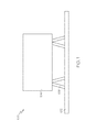
- FIG. 1 illustrates an exemplary system having vibration damping and isolation.
- the system 100 may be implemented in any one of numerous environments, such as in space, terrestrially, or under water.
- the system 100 includes a base 102, a payload 104, and at least one vibration isolation apparatus 106.
- the base 102 is configured to provide a platform to which the payload 104 and vibration isolation apparatus 106 are coupled and may be any one of numerous application-appropriate devices.
- the base 102 can be a satellite, an arm of a satellite, a space station, or any one of numerous other conventionally-used space apparatus.
- the payload 104 is a device that preferably needs vibration damping and isolation to operate effectively.
- the payload 104 may be any one of numerous devices, such as, for example, a telescope, or a camera.
- the vibration isolation apparatus 106 dampens and isolates vibration that may be experienced by the payload 104 and thus, is coupled between the payload 104 and the base 102. Although a single vibration isolation apparatus 106 may be used, it may be preferable to employ more than one vibration isolation apparatus 106. In one exemplary embodiment, three vibration isolation apparatus 106 are used in a three-point-mount configuration to isolate vibration. In another exemplary embodiment, six vibration isolation apparatus 106 are implemented in a hexapod configuration to provide vibration isolation. In still another exemplary embodiment, eight vibration isolation apparatus 106 are implemented in an octopod configuration to provide vibration isolation. In the embodiments described above, vibration isolation is provided in six degrees of freedom.
- the vibration isolation apparatus 106 includes a first support 108, a tuning spring 110, a stinger piece 112, a damper assembly 114, and a second support 116.
- the second support 116 receives vibratory motion from the base 102 and couples the base 102 to the vibration isolation apparatus 106.
- the damper assembly 114 is coupled to the second support 116, and provides the damping associated with the vibration isolation apparatus 106.
- Damper assembly 114 is coupled to stinger piece 112, which is coupled to the tuning spring 110.
- Tuning spring 110 is coupled to the first support 108, which in turn couples the vibration isolation apparatus to the payload 104.
- the series combination of the first support 108, tuning spring 110, stinger piece 112, damper assembly 114, and second support 116 provide the desired three-parameter vibration isolation properties (Ka, Kb, and Ca parameters).
- the damper assembly 114 includes an assembly housing 118, a first bellows 120, a second bellows 122, a first shaft 124, a second shaft 126, an external shaft 128, fluid and, optionally, a temperature compensation device 130.
- the first shaft 124 is coupled to the external shaft 128 via first connection member 132.
- the second shaft is couple to the external shaft via second connection member 134.
- the series connections of first shaft 124, first connection member 132, external shaft 128, second connection member 134, and second shaft 126 are designed to rigidly couple the ends of the first bellows 120 and second bellows 122, such that extension of one of the bellows results in equal compression to the other bellows.
- the assembly housing 118 is configured to operate with the other components of the damper assembly 114 to provide a fixed volume of space and to enclose and seal the fluid therein.
- the assembly housing 118 includes at least a tubular structure 136 that has a first end 138, a second end 140, and an inner surface 142 that connects with a passage 144 extending between the first and second ends 138, 140.
- the assembly housing 118 also includes a longitudinal axis 146 along which the vibration is received and the vibration is damped.
- the first end 138 includes an inlet 148
- the second end 140 includes an outlet 141
- the tube 136 has no openings other than the inlet 148 and outlet 141.
- the tube 136 may be a single component having endwalls integrally formed or coupled to each of the first and second ends 138, 140.
- the assembly housing 118 includes a damping plate 152 disposed in the middle thereof.
- the damping plate 152 is integrally formed or integrated as part of the assembly housing 118 and includes the passage 144 that extends through the damping plate 152.
- the first bellows 120 is disposed within the assembly housing 118 and is preferably configured to move along the longitudinal axis 146.
- the first bellows 120 is coupled at one end to a first end plate 149 and at an opposite end to a second end plate 151 to thereby define first bellows interior cavity 153 therebetween.
- the first end plate 149 sealingly mates with the assembly housing first end 138 and couples the first bellows 120 thereto.
- the second end plate 151 couples to the first shaft 124 that is disposed within the first bellows interior cavity 153.
- the first shaft 124 is configured to provide structural support for the first bellows 120 and guides the first bellows 120 along the longitudinal axis 146 during operation.
- the first end plate 149 includes an opening 162 formed therein that is configured to accommodate components that may extend outside of the assembly housing 118, such as the first shaft 124.
- the second bellows 122 is disposed within the assembly housing 118, is coupled to a first and a second end plate 166, 168, and is preferably configured to move along the longitudinal axis 146. Although depicted as being capable of traveling along the same axis 146 as the first bellows 120, it will be appreciated that in other non-illustrated embodiments the second bellows 122 may move along any other suitable axis.
- the second bellows first end plate 166 sealingly mates with the assembly housing second end 140 and couples the second bellows 122 thereto.
- the second bellows second end plate 168 is coupled to the opposite end of the second bellows 122 and, together with the first end plate 166 and inner surface of the second bellows 122, defines an interior cavity 170.
- the second end plate 168 couples to a second shaft 126 that is disposed within the second bellows interior cavity 170.
- the second shaft 126 is configured to provide structural support for the second bellows 122 and guides the second bellows 122 along the longitudinal axis 146 during operation.
- the second shaft 126 also couples with the stinger piece 112.
- the first end plate 166 includes opening 172 formed therein that are configured to provide space for disposal of components that may extend outside of the assembly housing 118, in this case, the second shaft 126.
- the isolation assembly also includes an external shaft 128.
- the external shaft 128 is positioned exterior to the assembly housing 118.
- the external shaft 128 includes first and second annular portions 191 and 192.
- First annular portion 191 extends at least part-way around the first end 138, and the second annular portion 192 extends at least part-way around the second end 140.
- the shaft 190 further includes at least one, and preferably two, three, or more longitudinal portions 193 that extend parallel to axis 146 longitudinally between the first and second annular portions 191, 192, exterior to assembly housing 118.
- the external shaft 128 is coupled to the first and second bellows 120, 122.
- the external shaft 128 couples to the first bellows 120 via the rigid, first connection member 132 and the first shaft 124.
- the external shaft 128 couples to the second bellows 122 via the rigid, second connection member 134 and the second shaft 126.
- the rigid connection members 132, 134 are configured as a structure having multiple extending portions 196, the number of extending portions 196 being the same as the number of longitudinal portions 193.
- Each extending portion 196 connects, at one end, with the external shaft 128 at a point that is roughly adjacent to an end of a respective longitudinal portion 193.
- Each extending portion 196 connects, at the other end thereof, with the other extending portions 196, at a center portion 197 of the members 132, 134.
- the first connection member 132 is coupled with first bellows 120 via a sliding association over first shaft 124, and via abutting contact with the second end plate 151, at the center portion 197 thereof.
- the second connection member 134 is coupled with the second bellows 122 via a sliding association over second shaft 126, and via abutting contact with the second end plate 168, at the center portion 197 thereof.
- the second connection member 134 is further coupled with the stinger piece 112 at the center portion thereof.
- the external shaft 128 is configured to operate with the first and second bellows 120, 122 to damp and isolate vibration received from the stinger piece 112.
- Other configurations of external shaft 128 that accomplish the same function as the exemplary configuration illustrated in the figures will also be appreciated by those having ordinary skill in the art.
- the damper assembly 114 components are preferably configured to operate together to sealingly enclose the fluid therein in a fixed volume of space.
- the volume of space is separated into subvolumes, each of which is disposed in a first chamber 182, a second chamber 184, and the restrictive flow passage 139.
- the first chamber 182 is defined by a portion of the assembly housing inner surface 135 and an outer surface of the first bellows 120, as well as second end plate 151 and first shaft 124
- the second chamber 184 is defined by another portion of the assembly housing inner surface 135 and an outer surface of the second bellows 122, as well as second end plate 168 and second shaft 126.
- the restrictive flow passage 139 allows the first and second chambers 182, 184 to communication with one another and may have any one of numerous configurations.
- the restrictive flow passage is configured as a cylindrical duct through the damping plate 152. No matter the particular configuration, the first chamber 182, second chamber 184, and restrictive flow passage 139 are filled with fluid.
- a force is exerted on the assembly housing 118 (for example from second support 116)
- fluid is pushed from the second chamber 184, through the restrictive flow passage 139, into the first chamber 182.
- the temperature compensation device 130 may be included in the damper assembly 114 to compensate for fluid expansion and/or contraction in response to temperature changes.
- the temperature compensation device 130 may have any one of numerous suitable configurations and may be disposed within the damper assembly 114 in any one of numerous manners.
- the isolation strut is usable with a thin fluid and to accommodate large rotations.
- the isolation strut has a simple configuration that is relatively inexpensive to implement.
Landscapes
- Engineering & Computer Science (AREA)
- General Engineering & Computer Science (AREA)
- Mechanical Engineering (AREA)
- Physics & Mathematics (AREA)
- Acoustics & Sound (AREA)
- Aviation & Aerospace Engineering (AREA)
- Vibration Prevention Devices (AREA)
- Fluid-Damping Devices (AREA)
- Combined Devices Of Dampers And Springs (AREA)
- Sealing Devices (AREA)
Abstract
Description
- The present invention generally relates to vibration damping and isolation systems, and more particularly relates to isolators.
- A precision pointing system carrying a sensor, such as a telescope as its payload, may be susceptible to disturbances that produce structural vibrations and, consequently, pointing errors. Such vibrations may be attributed to mechanical components or assemblies, such as reaction wheel assemblies that are used as actuators in the precision pointing system. For the most part, because these systems tend not to have significant, inherent damping, these structural vibrations may degrade system performance and even cause structural fatigue over time. Therefore, an efficient means of providing damping and isolation to the system may be needed.
- Typically, to minimize performance degradation caused by vibrations, a passive damping and isolation system is used for damping the structure and isolating the payload carried by a precision isolation system. One example of a passive damping and isolation system is the D-STRUT™ isolation strut, manufactured by Honeywell International Inc. of Morristown, N.J. The D-STRUT™ isolation strut is a three-parameter vibration isolation system that mechanically acts like a spring (KA) in parallel with a series spring (KB) and damper (CA) and is disclosed in
U.S. Pat. No. 5,332,070 entitled "Three Parameter Viscous Damper and Isolator" by Davis et al. This patent is hereby incorporated by reference. - The D-STRUT™ isolation strut includes a hollow shaft and a piston that is configured to move relative to the shaft. The piston includes a flange that extends radially from a midsection thereof. The flange has a top surface that is coupled to a first sealed bellows and a bottom surface that is coupled to a second sealed bellows. Each of the bellows has a chamber that is filled with fluid. Thus, when the piston moves axially through the shaft, fluid flows from one of the bellows chambers to the other.
- Although the conventional D-STRUT™ isolation strut operates effectively in most applications, it may not be appropriate to implement in other applications. For example, in some implementations that require a low-viscosity ("thin") fluid and are required to accommodate relatively large rotations, a configuration using the conventional shaft between the bellows chambers may not be suitable. The reason for using a low viscosity fluid is to permit operation in lower temperature environments (lower pour point and lower temp at which gelling occurs).
- Accordingly, it is desirable to have an isolation strut that is capable of damping and isolating vibration. In addition, it is desirable for the isolation strut to be usable with a low-viscosity fluid and to accommodate large rotations. Moreover, it is desirable for the isolation strut to have a simple configuration that is relatively inexpensive to implement. Furthermore, other desirable features and characteristics of the present invention will become apparent from the subsequent detailed description of the invention and the appended claims, taken in conjunction with the accompanying drawings and this background of the invention.
- An apparatus is provided for vibration damping and isolation. In one exemplary embodiment, the apparatus includes a housing having an inner surface defining a passage therethrough, a first bellows disposed within the housing passage, the first bellows having an outer surface and spaced apart from the housing inner surface to define a first chamber having a volume, and a second bellows disposed within the housing passage, the second bellows having an outer surface and spaced apart from the housing inner surface to define a second chamber having a volume. The apparatus further includes a restrictive flow passage in fluid communication with the first and second chambers, fluid disposed within the first chamber, the second chamber, and the restrictive flow passage, and a shaft positioned externally to the housing and coupled with the first bellows and the second bellows. The shaft is configured to selectively receive a force to thereby move the fluid through the restrictive flow passage to increase the first chamber volume and decrease the second chamber volume or to decrease the first chamber volume and increase the second chamber volume.
- This brief summary is provided to introduce a selection of concepts in a simplified form that are further described below in the detailed description. This summary is not intended to identify key features or essential features of the claimed subject matter, nor is it intended to be used as an aid in determining the scope of the claimed subject matter.
- The present invention will hereinafter be described in conjunction with the following drawing figures, wherein like numerals denote like elements, and wherein:
-
FIG. 1 is a schematic of an exemplary system having vibration damping and isolation; -
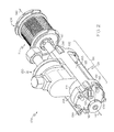
FIG. 2 is an isometric projection view of an exemplary vibration damping system in accordance with various embodiments of the present disclosure; -
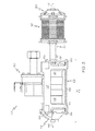
FIG. 3 is a side view of the exemplary vibration damping system shown inFIG. 2 ; and -
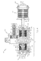
FIG. 4 is a cross-sectional view of the exemplary vibration damping system based on the side view shown inFIG. 3 . - The following detailed description is merely exemplary in nature and is not intended to limit the invention or the application and uses of the invention. As used herein, the word "exemplary" means "serving as an example, instance, or illustration." Thus, any embodiment described herein as "exemplary" is not necessarily to be construed as preferred or advantageous over other embodiments. All of the embodiments described herein are exemplary embodiments provided to enable persons skilled in the art to make or use the invention and not to limit the scope of the invention which is defined by the claims. While the isolation struts are discussed with reference to exemplary embodiments, any one of numerous other embodiments of a fluid filled isolation strut may be implemented as well. Fluid, as used in the present invention, can be any viscous liquid or any gas known in the art. Furthermore, there is no intention to be bound by any expressed or implied theory presented in the preceding technical field, background, brief summary, or the following detailed description.
- Embodiments of the present disclosure are generally directed to improved vibration isolation and damping systems. The disclosed embodiments take the conventionally-employed internal through-shaft out of the damper and wrap it around the entire damper housing. Thus, instead of an annulus used for damping that a through-shaft provides, the damping will now come from an annular orifice. The external through-shaft provides the same relative motion that the conventional, internal through-shaft configuration would provide. As such, the systems can a) have very thin fluid for cold temperature environments and b) handle large rotations that with the conventional internal through-shaft would prove unattainable.
-
FIG. 1 illustrates an exemplary system having vibration damping and isolation. Thesystem 100 may be implemented in any one of numerous environments, such as in space, terrestrially, or under water. Thesystem 100 includes abase 102, apayload 104, and at least onevibration isolation apparatus 106. Thebase 102 is configured to provide a platform to which thepayload 104 andvibration isolation apparatus 106 are coupled and may be any one of numerous application-appropriate devices. For example, in a space application, thebase 102 can be a satellite, an arm of a satellite, a space station, or any one of numerous other conventionally-used space apparatus. Thepayload 104 is a device that preferably needs vibration damping and isolation to operate effectively. Thepayload 104 may be any one of numerous devices, such as, for example, a telescope, or a camera. - The
vibration isolation apparatus 106 dampens and isolates vibration that may be experienced by thepayload 104 and thus, is coupled between thepayload 104 and thebase 102. Although a singlevibration isolation apparatus 106 may be used, it may be preferable to employ more than onevibration isolation apparatus 106. In one exemplary embodiment, threevibration isolation apparatus 106 are used in a three-point-mount configuration to isolate vibration. In another exemplary embodiment, sixvibration isolation apparatus 106 are implemented in a hexapod configuration to provide vibration isolation. In still another exemplary embodiment, eightvibration isolation apparatus 106 are implemented in an octopod configuration to provide vibration isolation. In the embodiments described above, vibration isolation is provided in six degrees of freedom. - With reference now to
FIGS. 2 - 4 , one exemplaryvibration isolation apparatus 106 is provided. Thevibration isolation apparatus 106 includes afirst support 108, atuning spring 110, astinger piece 112, adamper assembly 114, and asecond support 116. Thesecond support 116 receives vibratory motion from thebase 102 and couples the base 102 to thevibration isolation apparatus 106. Thedamper assembly 114 is coupled to thesecond support 116, and provides the damping associated with thevibration isolation apparatus 106.Damper assembly 114 is coupled tostinger piece 112, which is coupled to thetuning spring 110.Tuning spring 110 is coupled to thefirst support 108, which in turn couples the vibration isolation apparatus to thepayload 104. The series combination of thefirst support 108, tuningspring 110,stinger piece 112,damper assembly 114, andsecond support 116 provide the desired three-parameter vibration isolation properties (Ka, Kb, and Ca parameters). - The
damper assembly 114 includes anassembly housing 118, a first bellows 120, a second bellows 122, a first shaft 124, asecond shaft 126, anexternal shaft 128, fluid and, optionally, atemperature compensation device 130. The first shaft 124 is coupled to theexternal shaft 128 viafirst connection member 132. The second shaft is couple to the external shaft viasecond connection member 134. The series connections of first shaft 124,first connection member 132,external shaft 128,second connection member 134, andsecond shaft 126 are designed to rigidly couple the ends of thefirst bellows 120 andsecond bellows 122, such that extension of one of the bellows results in equal compression to the other bellows. - The
assembly housing 118 is configured to operate with the other components of thedamper assembly 114 to provide a fixed volume of space and to enclose and seal the fluid therein. Theassembly housing 118 includes at least atubular structure 136 that has afirst end 138, asecond end 140, and aninner surface 142 that connects with apassage 144 extending between the first and second ends 138, 140. Theassembly housing 118 also includes alongitudinal axis 146 along which the vibration is received and the vibration is damped. Preferably, thefirst end 138 includes aninlet 148, thesecond end 140 includes an outlet 141, and thetube 136 has no openings other than theinlet 148 and outlet 141. However, in alternate embodiments, thetube 136 may be a single component having endwalls integrally formed or coupled to each of the first and second ends 138, 140. - In one exemplary embodiment, the
assembly housing 118 includes a dampingplate 152 disposed in the middle thereof. The dampingplate 152 is integrally formed or integrated as part of theassembly housing 118 and includes thepassage 144 that extends through the dampingplate 152. - The first bellows 120 is disposed within the
assembly housing 118 and is preferably configured to move along thelongitudinal axis 146. The first bellows 120 is coupled at one end to afirst end plate 149 and at an opposite end to asecond end plate 151 to thereby define first bellowsinterior cavity 153 therebetween. Thefirst end plate 149 sealingly mates with the assembly housingfirst end 138 and couples thefirst bellows 120 thereto. Thesecond end plate 151 couples to the first shaft 124 that is disposed within the first bellowsinterior cavity 153. The first shaft 124 is configured to provide structural support for thefirst bellows 120 and guides thefirst bellows 120 along thelongitudinal axis 146 during operation. It will be appreciated that thefirst end plate 149 includes anopening 162 formed therein that is configured to accommodate components that may extend outside of theassembly housing 118, such as the first shaft 124. - Similar to the first bellows 120, the second bellows 122 is disposed within the
assembly housing 118, is coupled to a first and asecond end plate longitudinal axis 146. Although depicted as being capable of traveling along thesame axis 146 as the first bellows 120, it will be appreciated that in other non-illustrated embodiments the second bellows 122 may move along any other suitable axis. The second bellowsfirst end plate 166 sealingly mates with the assembly housingsecond end 140 and couples the second bellows 122 thereto. The second bellowssecond end plate 168 is coupled to the opposite end of the second bellows 122 and, together with thefirst end plate 166 and inner surface of the second bellows 122, defines aninterior cavity 170. Thesecond end plate 168 couples to asecond shaft 126 that is disposed within the second bellowsinterior cavity 170. Thesecond shaft 126 is configured to provide structural support for the second bellows 122 and guides the second bellows 122 along thelongitudinal axis 146 during operation. Thesecond shaft 126 also couples with thestinger piece 112. Just as above, thefirst end plate 166 includes opening 172 formed therein that are configured to provide space for disposal of components that may extend outside of theassembly housing 118, in this case, thesecond shaft 126. - The isolation assembly also includes an
external shaft 128. Theexternal shaft 128 is positioned exterior to theassembly housing 118. Theexternal shaft 128 includes first and secondannular portions annular portion 191 extends at least part-way around thefirst end 138, and the secondannular portion 192 extends at least part-way around thesecond end 140. The shaft 190 further includes at least one, and preferably two, three, or morelongitudinal portions 193 that extend parallel toaxis 146 longitudinally between the first and secondannular portions assembly housing 118. Theexternal shaft 128 is coupled to the first andsecond bellows external shaft 128 couples to thefirst bellows 120 via the rigid,first connection member 132 and the first shaft 124. Theexternal shaft 128 couples to the second bellows 122 via the rigid,second connection member 134 and thesecond shaft 126. Preferably, therigid connection members portions 196, the number of extendingportions 196 being the same as the number oflongitudinal portions 193. Each extendingportion 196 connects, at one end, with theexternal shaft 128 at a point that is roughly adjacent to an end of a respectivelongitudinal portion 193. Each extendingportion 196 connects, at the other end thereof, with the other extendingportions 196, at acenter portion 197 of themembers first connection member 132 is coupled withfirst bellows 120 via a sliding association over first shaft 124, and via abutting contact with thesecond end plate 151, at thecenter portion 197 thereof. Thesecond connection member 134 is coupled with the second bellows 122 via a sliding association oversecond shaft 126, and via abutting contact with thesecond end plate 168, at thecenter portion 197 thereof. Thesecond connection member 134 is further coupled with thestinger piece 112 at the center portion thereof. Theexternal shaft 128 is configured to operate with the first andsecond bellows stinger piece 112. Other configurations ofexternal shaft 128 that accomplish the same function as the exemplary configuration illustrated in the figures will also be appreciated by those having ordinary skill in the art. - As briefly mentioned previously, the
damper assembly 114 components are preferably configured to operate together to sealingly enclose the fluid therein in a fixed volume of space. The volume of space is separated into subvolumes, each of which is disposed in afirst chamber 182, asecond chamber 184, and the restrictive flow passage 139. Thefirst chamber 182 is defined by a portion of the assembly housinginner surface 135 and an outer surface of the first bellows 120, as well assecond end plate 151 and first shaft 124, and thesecond chamber 184 is defined by another portion of the assembly housinginner surface 135 and an outer surface of the second bellows 122, as well assecond end plate 168 andsecond shaft 126. The restrictive flow passage 139 allows the first andsecond chambers plate 152. No matter the particular configuration, thefirst chamber 182,second chamber 184, and restrictive flow passage 139 are filled with fluid. Thus, during the operation of thedamper assembly 114, when a force is exerted on the assembly housing 118 (for example from second support 116), fluid is pushed from thesecond chamber 184, through the restrictive flow passage 139, into thefirst chamber 182. - The
temperature compensation device 130 may be included in thedamper assembly 114 to compensate for fluid expansion and/or contraction in response to temperature changes. Thetemperature compensation device 130 may have any one of numerous suitable configurations and may be disposed within thedamper assembly 114 in any one of numerous manners. - There has now been provided a vibration isolator that is capable of damping and isolating vibration. In addition, the isolation strut is usable with a thin fluid and to accommodate large rotations. Moreover, the isolation strut has a simple configuration that is relatively inexpensive to implement.
- While at least one exemplary embodiment has been presented in the foregoing detailed description of the invention, it should be appreciated that a vast number of variations exist. It should also be appreciated that the exemplary embodiment or exemplary embodiments are only examples, and are not intended to limit the scope, applicability, or configuration of the invention in any way. Rather, the foregoing detailed description will provide those skilled in the art with a convenient road map for implementing an exemplary embodiment of the invention. It being understood that various changes may be made in the function and arrangement of elements described in an exemplary embodiment without departing from the scope of the invention as set forth in the appended claims.
Claims (10)
- A damping system, comprising:a housing having an inner surface defining a passage therethrough;a first bellows disposed within the housing passage, the first bellows having an outer surface and spaced apart from the housing inner surface to define a first chamber having a volume;a second bellows disposed within the housing passage, the second bellows having an outer surface and spaced apart from the housing inner surface to define a second chamber having a volume;a restrictive flow passage in fluid communication with the first and second chambers;fluid disposed within the first chamber, the second chamber, and the restrictive flow passage; anda shaft positioned externally to the housing and coupled with the first bellows and the second bellows, the shaft configured to selectively receive a force to thereby move the fluid through the restrictive flow passage to increase the first chamber volume and decrease the second chamber volume or to decrease the first chamber volume and increase the second chamber volume.
- The damping system of claim 1, wherein the shaft comprises first and second annular portions disposed annularly around the housing and a longitudinal portion connected between the first and second annular portions and disposed longitudinally along the housing.
- The damping system of claim 1, further comprising: a damping plate disposed with the housing passage between the first and second bellows, the damping plate coupled to the housing inner surface and extending radially inward and including at least one duct formed therethrough, wherein at least a portion of the restrictive flow passage is defined by the at least one duct.
- The damping system of claim 1, wherein the first bellows has an inner surface defining a cavity therein, the cavity each enclosing a support shaft, the support shaft being slidingly associated with the external shaft.
- The damping system of claim 4, wherein the second bellows has an inner surface defining a cavity therein, the cavity each enclosing a support shaft, the support shaft being slidingly associated with the external shaft.
- The damping system of claim 1, further comprising: a temperature compensator.
- The damping system of claim 6, wherein the temperature compensator is disposed external to the housing, the temperature compensator configured to compensate for expansion and contraction of the fluid during temperature changes.
- An isolator system comprising:a housing having a first end, a second end, an inner surface, and a passage defined by the inner surface in the first and second ends;a first bellows disposed within the housing passage and having a first end, a second end, and an outer surface, the first bellows first end coupled to the housing first end, the first bellows second end having a surface, and the first bellows outer surface and housing inner surface defining a first chamber having a volume;a second bellows disposed within the housing passage and having a first end, a second end, an inner surface, and an outer surface, the second bellows first end coupled to the housing second end, the second bellows inner surface defining a cavity therein, and the second bellows outer surface and housing inner surface defining a second chamber having a volume;fluid disposed at least within the first chamber, the second chamber, and the flowpath;a shaft positioned externally to the housing and coupled with the first bellows and the second bellows, the shaft configured to selectively receive a force to thereby move the fluid through the restrictive flow passage to increase the first chamber volume and decrease the second chamber volume or to decrease the first chamber volume and increase the second chamber volume; andthe cavities of the first and second bellows each enclosing a support shaft, the support shafts being slidingly associated with the external shaft.
- The isolator system of claim 8, wherein the fluid is a gas or wherein the fluid is a liquid.
- An isolator system comprising:a housing having a first end, a second end, a plate, an inner surface, and a passage extending between the first and second ends, the plate disposed in the passage and having a first side, a second side, and a passage formed therebetween, a first section of the housing inner surface and the plate first side defining a first chamber having a volume, a second section of the housing inner surface and the plate second side defining a second chamber having a volume, and the passage configured to provide fluid communication between the first and second chambers;a first bellows disposed within the housing first chamber and having a first end, and a second end, the first bellows first end coupled to the housing first end, the first bellows second end having a surface;a second bellows disposed within the housing second chamber and having a first end, a second end, and an inner surface, the second bellows first end coupled to the housing second end, the second bellows inner surface defining a cavity therein;fluid disposed within the first chamber, the second chamber, and the passage;a shaft positioned externally to the housing and coupled with the first bellows and the second bellows, the shaft configured to selectively receive a force to thereby move the fluid through the restrictive flow passage to increase the first chamber volume and decrease the second chamber volume or to decrease the first chamber volume and increase the second chamber volume; andthe cavities of the first and second bellows each enclosing a support shaft, the support shafts being slidingly associated with the external shaft.
Applications Claiming Priority (1)
| Application Number | Priority Date | Filing Date | Title |
|---|---|---|---|
| US14/182,827 US9587702B2 (en) | 2014-02-18 | 2014-02-18 | Vibration isolator using externally pressurized sealing bellows and an external shaft |
Publications (3)
| Publication Number | Publication Date |
|---|---|
| EP2921741A2 true EP2921741A2 (en) | 2015-09-23 |
| EP2921741A3 EP2921741A3 (en) | 2016-01-06 |
| EP2921741B1 EP2921741B1 (en) | 2025-11-05 |
Family
ID=52577608
Family Applications (1)
| Application Number | Title | Priority Date | Filing Date |
|---|---|---|---|
| EP15153674.5A Active EP2921741B1 (en) | 2014-02-18 | 2015-02-03 | Vibration isolator using externally pressurized sealing bellows and an external shaft |
Country Status (3)
| Country | Link |
|---|---|
| US (1) | US9587702B2 (en) |
| EP (1) | EP2921741B1 (en) |
| JP (1) | JP6608594B2 (en) |
Cited By (1)
| Publication number | Priority date | Publication date | Assignee | Title |
|---|---|---|---|---|
| CN111486189A (en) * | 2020-04-16 | 2020-08-04 | 北京空间飞行器总体设计部 | A reusable small celestial body surface attachment buffer mechanism |
Families Citing this family (5)
| Publication number | Priority date | Publication date | Assignee | Title |
|---|---|---|---|---|
| DE102017104250B3 (en) * | 2017-03-01 | 2018-05-30 | Lisa Dräxlmaier GmbH | Rotary damper with constant friction coefficient |
| CN108489741B (en) * | 2018-03-26 | 2020-07-24 | 扬州大学 | Device for detecting cavity failure and oil impact of automobile hydraulic shock absorber |
| US11313433B2 (en) * | 2020-01-15 | 2022-04-26 | Raytheon Company | Shock isolator assembly for a vehicle mounted payload |
| US11041539B1 (en) | 2020-10-05 | 2021-06-22 | United States Of America As Represented By The Administrator Of Nasa | Bi-directional damping system |
| US11111980B1 (en) | 2021-03-30 | 2021-09-07 | United States Of America As Represented By The Administrator Of Nasa | Unidirectional damping system |
Citations (1)
| Publication number | Priority date | Publication date | Assignee | Title |
|---|---|---|---|---|
| US5332070A (en) | 1993-04-21 | 1994-07-26 | Honeywell Inc. | Three parameter viscous damper and isolator |
Family Cites Families (32)
| Publication number | Priority date | Publication date | Assignee | Title |
|---|---|---|---|---|
| FR952367A (en) | 1947-08-14 | 1949-11-16 | Morane Saulnier | Sophisticated suspension |
| US2942838A (en) | 1955-03-18 | 1960-06-28 | Melville F Peters | Vibration damping in fluid seals |
| US2919883A (en) | 1958-12-11 | 1960-01-05 | Bendix Aviat Corp | Liquid damped vibration isolator |
| GB1175255A (en) * | 1967-10-18 | 1969-12-23 | Nuclear Power Group Ltd | Improvements in or relating to Dash Pots. |
| DE2553504A1 (en) | 1975-11-28 | 1977-06-02 | Weser Ag | VIBRATION DAMPERS ESPECIALLY FOR LARGE DIMENSIONS |
| DE2935935C2 (en) | 1979-09-06 | 1981-12-17 | Boge Gmbh, 5208 Eitorf | Hydraulic vibration damper with two coaxially arranged bellows |
| EP0130826A1 (en) * | 1983-07-05 | 1985-01-09 | South African Inventions Development Corporation | Hydraulic dampers |
| US4572488A (en) * | 1983-12-08 | 1986-02-25 | The United States Of America As Represented By The Secretary Of The Air Force | Low temperature rate controller |
| US4815574A (en) * | 1987-12-21 | 1989-03-28 | Tayco Developments, Inc. | Frictionless damper |
| US5305981A (en) * | 1991-10-31 | 1994-04-26 | Honeywell Inc. | Multiaxis vibration isolation system |
| US5873438A (en) | 1996-01-25 | 1999-02-23 | Honeywell Inc. | Tuned mass damper with tunable damping and anti friction rolling mass |
| DE19626548A1 (en) | 1996-07-02 | 1998-01-08 | Hottinger Messtechnik Baldwin | Hydraulic damper for suppressing oscillations of weighing system |
| US6082508A (en) | 1997-04-23 | 2000-07-04 | Honeywell International Inc. | Pneumatic damping strut |
| US6390254B1 (en) | 1997-07-10 | 2002-05-21 | Honeywell International Inc. | Constant volume damper |
| US6032936A (en) * | 1997-08-04 | 2000-03-07 | Lord Corporation | Fluid mount including a partitionless compensator |
| AU9776498A (en) | 1997-09-26 | 1999-04-23 | Vistek Inc. | Micro vibration isolation device |
| US6131709A (en) | 1997-11-25 | 2000-10-17 | Lord Corporation | Adjustable valve and vibration damper utilizing same |
| JP2001343045A (en) | 2000-03-30 | 2001-12-14 | Tokai Rubber Ind Ltd | Pneumatic vibration type fluid filled type vibration damping device |
| WO2003089781A1 (en) | 2002-04-22 | 2003-10-30 | Siemens Aktiengesellschaft | Dosing device for fluids, especially a motor vehicle injection valve |
| US6758466B2 (en) | 2002-11-06 | 2004-07-06 | Lord Corporation | Fluid-elastomeric damper assembly including internal pumping mechanism |
| US6896109B2 (en) * | 2003-04-07 | 2005-05-24 | Csa Engineering, Inc. | Magnetorheological fluid vibration isolator |
| US20050217954A1 (en) | 2004-03-31 | 2005-10-06 | Hindle Timothy A | Viscous isolation and damping strut utilizing a fluid mass effect |
| US7182188B2 (en) | 2005-02-16 | 2007-02-27 | Honeywell International, Inc. | Isolator using externally pressurized sealing bellows |
| WO2007015395A1 (en) | 2005-08-04 | 2007-02-08 | Bridgestone Corporation | Vibration damper |
| EP1954958A1 (en) | 2005-11-28 | 2008-08-13 | Lord Corporation | Isolated axial support strut for supporting an axial load and axial support strut isolator |
| US8308147B2 (en) | 2006-04-07 | 2012-11-13 | Bridgestone Corporation | Vibration damper |
| US8113321B2 (en) | 2006-05-06 | 2012-02-14 | Lord Corporation | Helicopter reduced vibration isolator axial support strut |
| JP5121197B2 (en) | 2006-09-22 | 2013-01-16 | 株式会社ブリヂストン | Vibration isolator |
| US8444121B2 (en) | 2008-03-31 | 2013-05-21 | Honeywell International Inc. | Systems for damping vibrations from a payload |
| CN101813154B (en) | 2009-02-24 | 2013-02-13 | 仓敷化工株式会社 | Liquid-filled vibration isolator |
| US9103403B2 (en) | 2011-04-25 | 2015-08-11 | Honeywell International Inc. | Three parameter, multi-axis isolators, isolation systems employing the same, and methods for producing the same |
| US20150226282A1 (en) * | 2014-02-11 | 2015-08-13 | Honeywell International Inc. | Isolators enabling large rotation angle capabilities with highly restricted damper orifices |
-
2014
- 2014-02-18 US US14/182,827 patent/US9587702B2/en active Active
-
2015
- 2015-02-03 EP EP15153674.5A patent/EP2921741B1/en active Active
- 2015-02-16 JP JP2015027429A patent/JP6608594B2/en active Active
Patent Citations (1)
| Publication number | Priority date | Publication date | Assignee | Title |
|---|---|---|---|---|
| US5332070A (en) | 1993-04-21 | 1994-07-26 | Honeywell Inc. | Three parameter viscous damper and isolator |
Cited By (1)
| Publication number | Priority date | Publication date | Assignee | Title |
|---|---|---|---|---|
| CN111486189A (en) * | 2020-04-16 | 2020-08-04 | 北京空间飞行器总体设计部 | A reusable small celestial body surface attachment buffer mechanism |
Also Published As
| Publication number | Publication date |
|---|---|
| EP2921741A3 (en) | 2016-01-06 |
| US9587702B2 (en) | 2017-03-07 |
| EP2921741B1 (en) | 2025-11-05 |
| JP2015163817A (en) | 2015-09-10 |
| US20150233441A1 (en) | 2015-08-20 |
| JP6608594B2 (en) | 2019-11-20 |
Similar Documents
| Publication | Publication Date | Title |
|---|---|---|
| US7182188B2 (en) | Isolator using externally pressurized sealing bellows | |
| EP2921741B1 (en) | Vibration isolator using externally pressurized sealing bellows and an external shaft | |
| US8327985B2 (en) | Two stage vibration isolator | |
| US9453552B2 (en) | Adaptive three parameter isolator assemblies including external magneto-rheological valves | |
| US9103403B2 (en) | Three parameter, multi-axis isolators, isolation systems employing the same, and methods for producing the same | |
| US4760996A (en) | Damper and isolator | |
| US9416842B2 (en) | Isolators having damper-external thermal compensators and spacecraft isolation systems employing the same | |
| JP6564212B2 (en) | Thin three-parameter vibration isolator and vibration isolating system using them | |
| US20130154170A1 (en) | Passive isolation devices providing low frequency damping of low mass payloads and spacecraft isolation systems employing the same | |
| JPH05238496A (en) | Seismic isolation and damping device for passive isolation of seismic motion between supporting and supported structures | |
| US8444121B2 (en) | Systems for damping vibrations from a payload | |
| US9670983B2 (en) | Isolators including damper assemblies having variable annuli and spacecraft isolation systems employing the same | |
| US10066697B2 (en) | Three parameter isolators containing rolling seal damper assemblies | |
| EP3121480B1 (en) | Isolators including main spring linear guide systems | |
| EP0623764B1 (en) | An adjustable viscous damper and isolator | |
| EP0339113B1 (en) | Vibration damper and isolator | |
| US9897162B2 (en) | Two-dimensional vibration isolator | |
| JP2770229B2 (en) | Vibration isolation and damping device | |
| CA1299592C (en) | Vibration damper and isolator | |
| Porter Davis et al. | Advanced 1.5 Hz Passive Viscous Isolation System |
Legal Events
| Date | Code | Title | Description |
|---|---|---|---|
| PUAI | Public reference made under article 153(3) epc to a published international application that has entered the european phase |
Free format text: ORIGINAL CODE: 0009012 |
|
| 17P | Request for examination filed |
Effective date: 20150203 |
|
| AK | Designated contracting states |
Kind code of ref document: A2 Designated state(s): AL AT BE BG CH CY CZ DE DK EE ES FI FR GB GR HR HU IE IS IT LI LT LU LV MC MK MT NL NO PL PT RO RS SE SI SK SM TR |
|
| AX | Request for extension of the european patent |
Extension state: BA ME |
|
| PUAL | Search report despatched |
Free format text: ORIGINAL CODE: 0009013 |
|
| RAP1 | Party data changed (applicant data changed or rights of an application transferred) |
Owner name: HONEYWELL INTERNATIONAL INC. |
|
| AK | Designated contracting states |
Kind code of ref document: A3 Designated state(s): AL AT BE BG CH CY CZ DE DK EE ES FI FR GB GR HR HU IE IS IT LI LT LU LV MC MK MT NL NO PL PT RO RS SE SI SK SM TR |
|
| AX | Request for extension of the european patent |
Extension state: BA ME |
|
| RIC1 | Information provided on ipc code assigned before grant |
Ipc: F16F 15/02 20060101AFI20151127BHEP Ipc: F16F 9/04 20060101ALI20151127BHEP |
|
| STAA | Information on the status of an ep patent application or granted ep patent |
Free format text: STATUS: EXAMINATION IS IN PROGRESS |
|
| 17Q | First examination report despatched |
Effective date: 20180712 |
|
| P01 | Opt-out of the competence of the unified patent court (upc) registered |
Effective date: 20230421 |
|
| GRAP | Despatch of communication of intention to grant a patent |
Free format text: ORIGINAL CODE: EPIDOSNIGR1 |
|
| STAA | Information on the status of an ep patent application or granted ep patent |
Free format text: STATUS: GRANT OF PATENT IS INTENDED |
|
| INTG | Intention to grant announced |
Effective date: 20250728 |
|
| GRAS | Grant fee paid |
Free format text: ORIGINAL CODE: EPIDOSNIGR3 |
|
| GRAA | (expected) grant |
Free format text: ORIGINAL CODE: 0009210 |
|
| STAA | Information on the status of an ep patent application or granted ep patent |
Free format text: STATUS: THE PATENT HAS BEEN GRANTED |
|
| AK | Designated contracting states |
Kind code of ref document: B1 Designated state(s): AL AT BE BG CH CY CZ DE DK EE ES FI FR GB GR HR HU IE IS IT LI LT LU LV MC MK MT NL NO PL PT RO RS SE SI SK SM TR |
|
| REG | Reference to a national code |
Ref country code: CH Ref legal event code: F10 Free format text: ST27 STATUS EVENT CODE: U-0-0-F10-F00 (AS PROVIDED BY THE NATIONAL OFFICE) Effective date: 20251105 Ref country code: GB Ref legal event code: FG4D |
|
| REG | Reference to a national code |
Ref country code: DE Ref legal event code: R096 Ref document number: 602015092608 Country of ref document: DE |
|
| REG | Reference to a national code |
Ref country code: IE Ref legal event code: FG4D |
|
| REG | Reference to a national code |
Ref country code: NL Ref legal event code: MP Effective date: 20251105 |
|
| PGFP | Annual fee paid to national office [announced via postgrant information from national office to epo] |
Ref country code: GB Payment date: 20260223 Year of fee payment: 12 |
|
| PG25 | Lapsed in a contracting state [announced via postgrant information from national office to epo] |
Ref country code: ES Free format text: LAPSE BECAUSE OF FAILURE TO SUBMIT A TRANSLATION OF THE DESCRIPTION OR TO PAY THE FEE WITHIN THE PRESCRIBED TIME-LIMIT Effective date: 20251105 |
|
| REG | Reference to a national code |
Ref country code: LT Ref legal event code: MG9D |
|
| PG25 | Lapsed in a contracting state [announced via postgrant information from national office to epo] |
Ref country code: NO Free format text: LAPSE BECAUSE OF FAILURE TO SUBMIT A TRANSLATION OF THE DESCRIPTION OR TO PAY THE FEE WITHIN THE PRESCRIBED TIME-LIMIT Effective date: 20260205 |
|
| PGFP | Annual fee paid to national office [announced via postgrant information from national office to epo] |
Ref country code: DE Payment date: 20260220 Year of fee payment: 12 |
|
| PG25 | Lapsed in a contracting state [announced via postgrant information from national office to epo] |
Ref country code: AT Free format text: LAPSE BECAUSE OF FAILURE TO SUBMIT A TRANSLATION OF THE DESCRIPTION OR TO PAY THE FEE WITHIN THE PRESCRIBED TIME-LIMIT Effective date: 20251105 Ref country code: HR Free format text: LAPSE BECAUSE OF FAILURE TO SUBMIT A TRANSLATION OF THE DESCRIPTION OR TO PAY THE FEE WITHIN THE PRESCRIBED TIME-LIMIT Effective date: 20251105 Ref country code: FI Free format text: LAPSE BECAUSE OF FAILURE TO SUBMIT A TRANSLATION OF THE DESCRIPTION OR TO PAY THE FEE WITHIN THE PRESCRIBED TIME-LIMIT Effective date: 20251105 |
|
| REG | Reference to a national code |
Ref country code: AT Ref legal event code: MK05 Ref document number: 1854628 Country of ref document: AT Kind code of ref document: T Effective date: 20251105 |
|
| PG25 | Lapsed in a contracting state [announced via postgrant information from national office to epo] |
Ref country code: NL Free format text: LAPSE BECAUSE OF FAILURE TO SUBMIT A TRANSLATION OF THE DESCRIPTION OR TO PAY THE FEE WITHIN THE PRESCRIBED TIME-LIMIT Effective date: 20251105 |
|
| PG25 | Lapsed in a contracting state [announced via postgrant information from national office to epo] |
Ref country code: RS Free format text: LAPSE BECAUSE OF FAILURE TO SUBMIT A TRANSLATION OF THE DESCRIPTION OR TO PAY THE FEE WITHIN THE PRESCRIBED TIME-LIMIT Effective date: 20260205 |
|
| PG25 | Lapsed in a contracting state [announced via postgrant information from national office to epo] |
Ref country code: IS Free format text: LAPSE BECAUSE OF FAILURE TO SUBMIT A TRANSLATION OF THE DESCRIPTION OR TO PAY THE FEE WITHIN THE PRESCRIBED TIME-LIMIT Effective date: 20260305 |
|
| PGFP | Annual fee paid to national office [announced via postgrant information from national office to epo] |
Ref country code: FR Payment date: 20260224 Year of fee payment: 12 |
|
| PG25 | Lapsed in a contracting state [announced via postgrant information from national office to epo] |
Ref country code: PT Free format text: LAPSE BECAUSE OF FAILURE TO SUBMIT A TRANSLATION OF THE DESCRIPTION OR TO PAY THE FEE WITHIN THE PRESCRIBED TIME-LIMIT Effective date: 20260305 |
|
| PG25 | Lapsed in a contracting state [announced via postgrant information from national office to epo] |
Ref country code: PL Free format text: LAPSE BECAUSE OF FAILURE TO SUBMIT A TRANSLATION OF THE DESCRIPTION OR TO PAY THE FEE WITHIN THE PRESCRIBED TIME-LIMIT Effective date: 20251105 |
|
| PG25 | Lapsed in a contracting state [announced via postgrant information from national office to epo] |
Ref country code: LV Free format text: LAPSE BECAUSE OF FAILURE TO SUBMIT A TRANSLATION OF THE DESCRIPTION OR TO PAY THE FEE WITHIN THE PRESCRIBED TIME-LIMIT Effective date: 20251105 |
|
| PG25 | Lapsed in a contracting state [announced via postgrant information from national office to epo] |
Ref country code: BG Free format text: LAPSE BECAUSE OF FAILURE TO SUBMIT A TRANSLATION OF THE DESCRIPTION OR TO PAY THE FEE WITHIN THE PRESCRIBED TIME-LIMIT Effective date: 20251105 |
|
| PG25 | Lapsed in a contracting state [announced via postgrant information from national office to epo] |
Ref country code: LT Free format text: LAPSE BECAUSE OF FAILURE TO SUBMIT A TRANSLATION OF THE DESCRIPTION OR TO PAY THE FEE WITHIN THE PRESCRIBED TIME-LIMIT Effective date: 20251105 |
|
| PG25 | Lapsed in a contracting state [announced via postgrant information from national office to epo] |
Ref country code: SM Free format text: LAPSE BECAUSE OF FAILURE TO SUBMIT A TRANSLATION OF THE DESCRIPTION OR TO PAY THE FEE WITHIN THE PRESCRIBED TIME-LIMIT Effective date: 20251105 |
|
| PG25 | Lapsed in a contracting state [announced via postgrant information from national office to epo] |
Ref country code: DK Free format text: LAPSE BECAUSE OF FAILURE TO SUBMIT A TRANSLATION OF THE DESCRIPTION OR TO PAY THE FEE WITHIN THE PRESCRIBED TIME-LIMIT Effective date: 20251105 |
|
| PG25 | Lapsed in a contracting state [announced via postgrant information from national office to epo] |
Ref country code: IT Free format text: LAPSE BECAUSE OF FAILURE TO SUBMIT A TRANSLATION OF THE DESCRIPTION OR TO PAY THE FEE WITHIN THE PRESCRIBED TIME-LIMIT Effective date: 20251105 |
|
| PG25 | Lapsed in a contracting state [announced via postgrant information from national office to epo] |
Ref country code: EE Free format text: LAPSE BECAUSE OF FAILURE TO SUBMIT A TRANSLATION OF THE DESCRIPTION OR TO PAY THE FEE WITHIN THE PRESCRIBED TIME-LIMIT Effective date: 20251105 |
|
| PG25 | Lapsed in a contracting state [announced via postgrant information from national office to epo] |
Ref country code: CZ Free format text: LAPSE BECAUSE OF FAILURE TO SUBMIT A TRANSLATION OF THE DESCRIPTION OR TO PAY THE FEE WITHIN THE PRESCRIBED TIME-LIMIT Effective date: 20251105 |
|
| PG25 | Lapsed in a contracting state [announced via postgrant information from national office to epo] |
Ref country code: SK Free format text: LAPSE BECAUSE OF FAILURE TO SUBMIT A TRANSLATION OF THE DESCRIPTION OR TO PAY THE FEE WITHIN THE PRESCRIBED TIME-LIMIT Effective date: 20251105 |
|
| PG25 | Lapsed in a contracting state [announced via postgrant information from national office to epo] |
Ref country code: SE Free format text: LAPSE BECAUSE OF FAILURE TO SUBMIT A TRANSLATION OF THE DESCRIPTION OR TO PAY THE FEE WITHIN THE PRESCRIBED TIME-LIMIT Effective date: 20251105 |