EP2921729A2 - Bearing arrangement - Google Patents
Bearing arrangement Download PDFInfo
- Publication number
- EP2921729A2 EP2921729A2 EP15156323.6A EP15156323A EP2921729A2 EP 2921729 A2 EP2921729 A2 EP 2921729A2 EP 15156323 A EP15156323 A EP 15156323A EP 2921729 A2 EP2921729 A2 EP 2921729A2
- Authority
- EP
- European Patent Office
- Prior art keywords
- thrust
- bearings
- bearing arrangement
- bearing
- thrust bearings
- Prior art date
- Legal status (The legal status is an assumption and is not a legal conclusion. Google has not performed a legal analysis and makes no representation as to the accuracy of the status listed.)
- Withdrawn
Links
Images



Classifications
-
- F—MECHANICAL ENGINEERING; LIGHTING; HEATING; WEAPONS; BLASTING
- F16—ENGINEERING ELEMENTS AND UNITS; GENERAL MEASURES FOR PRODUCING AND MAINTAINING EFFECTIVE FUNCTIONING OF MACHINES OR INSTALLATIONS; THERMAL INSULATION IN GENERAL
- F16C—SHAFTS; FLEXIBLE SHAFTS; ELEMENTS OR CRANKSHAFT MECHANISMS; ROTARY BODIES OTHER THAN GEARING ELEMENTS; BEARINGS
- F16C39/00—Relieving load on bearings
- F16C39/04—Relieving load on bearings using hydraulic or pneumatic means
-
- F—MECHANICAL ENGINEERING; LIGHTING; HEATING; WEAPONS; BLASTING
- F16—ENGINEERING ELEMENTS AND UNITS; GENERAL MEASURES FOR PRODUCING AND MAINTAINING EFFECTIVE FUNCTIONING OF MACHINES OR INSTALLATIONS; THERMAL INSULATION IN GENERAL
- F16C—SHAFTS; FLEXIBLE SHAFTS; ELEMENTS OR CRANKSHAFT MECHANISMS; ROTARY BODIES OTHER THAN GEARING ELEMENTS; BEARINGS
- F16C19/00—Bearings with rolling contact, for exclusively rotary movement
- F16C19/54—Systems consisting of a plurality of bearings with rolling friction
-
- F—MECHANICAL ENGINEERING; LIGHTING; HEATING; WEAPONS; BLASTING
- F16—ENGINEERING ELEMENTS AND UNITS; GENERAL MEASURES FOR PRODUCING AND MAINTAINING EFFECTIVE FUNCTIONING OF MACHINES OR INSTALLATIONS; THERMAL INSULATION IN GENERAL
- F16C—SHAFTS; FLEXIBLE SHAFTS; ELEMENTS OR CRANKSHAFT MECHANISMS; ROTARY BODIES OTHER THAN GEARING ELEMENTS; BEARINGS
- F16C19/00—Bearings with rolling contact, for exclusively rotary movement
- F16C19/54—Systems consisting of a plurality of bearings with rolling friction
- F16C19/546—Systems with spaced apart rolling bearings including at least one angular contact bearing
- F16C19/547—Systems with spaced apart rolling bearings including at least one angular contact bearing with two angular contact rolling bearings
-
- F—MECHANICAL ENGINEERING; LIGHTING; HEATING; WEAPONS; BLASTING
- F16—ENGINEERING ELEMENTS AND UNITS; GENERAL MEASURES FOR PRODUCING AND MAINTAINING EFFECTIVE FUNCTIONING OF MACHINES OR INSTALLATIONS; THERMAL INSULATION IN GENERAL
- F16C—SHAFTS; FLEXIBLE SHAFTS; ELEMENTS OR CRANKSHAFT MECHANISMS; ROTARY BODIES OTHER THAN GEARING ELEMENTS; BEARINGS
- F16C25/00—Bearings for exclusively rotary movement adjustable for wear or play
- F16C25/06—Ball or roller bearings
- F16C25/08—Ball or roller bearings self-adjusting
-
- F—MECHANICAL ENGINEERING; LIGHTING; HEATING; WEAPONS; BLASTING
- F16—ENGINEERING ELEMENTS AND UNITS; GENERAL MEASURES FOR PRODUCING AND MAINTAINING EFFECTIVE FUNCTIONING OF MACHINES OR INSTALLATIONS; THERMAL INSULATION IN GENERAL
- F16C—SHAFTS; FLEXIBLE SHAFTS; ELEMENTS OR CRANKSHAFT MECHANISMS; ROTARY BODIES OTHER THAN GEARING ELEMENTS; BEARINGS
- F16C41/00—Other accessories, e.g. devices integrated in the bearing not relating to the bearing function as such
- F16C41/02—Arrangements for equalising the load on a plurality of bearings or their elements
-
- F—MECHANICAL ENGINEERING; LIGHTING; HEATING; WEAPONS; BLASTING
- F16—ENGINEERING ELEMENTS AND UNITS; GENERAL MEASURES FOR PRODUCING AND MAINTAINING EFFECTIVE FUNCTIONING OF MACHINES OR INSTALLATIONS; THERMAL INSULATION IN GENERAL
- F16C—SHAFTS; FLEXIBLE SHAFTS; ELEMENTS OR CRANKSHAFT MECHANISMS; ROTARY BODIES OTHER THAN GEARING ELEMENTS; BEARINGS
- F16C19/00—Bearings with rolling contact, for exclusively rotary movement
- F16C19/02—Bearings with rolling contact, for exclusively rotary movement with bearing balls essentially of the same size in one or more circular rows
- F16C19/14—Bearings with rolling contact, for exclusively rotary movement with bearing balls essentially of the same size in one or more circular rows for both radial and axial load
- F16C19/16—Bearings with rolling contact, for exclusively rotary movement with bearing balls essentially of the same size in one or more circular rows for both radial and axial load with a single row of balls
-
- F—MECHANICAL ENGINEERING; LIGHTING; HEATING; WEAPONS; BLASTING
- F16—ENGINEERING ELEMENTS AND UNITS; GENERAL MEASURES FOR PRODUCING AND MAINTAINING EFFECTIVE FUNCTIONING OF MACHINES OR INSTALLATIONS; THERMAL INSULATION IN GENERAL
- F16C—SHAFTS; FLEXIBLE SHAFTS; ELEMENTS OR CRANKSHAFT MECHANISMS; ROTARY BODIES OTHER THAN GEARING ELEMENTS; BEARINGS
- F16C2360/00—Engines or pumps
- F16C2360/23—Gas turbine engines
-
- F—MECHANICAL ENGINEERING; LIGHTING; HEATING; WEAPONS; BLASTING
- F16—ENGINEERING ELEMENTS AND UNITS; GENERAL MEASURES FOR PRODUCING AND MAINTAINING EFFECTIVE FUNCTIONING OF MACHINES OR INSTALLATIONS; THERMAL INSULATION IN GENERAL
- F16C—SHAFTS; FLEXIBLE SHAFTS; ELEMENTS OR CRANKSHAFT MECHANISMS; ROTARY BODIES OTHER THAN GEARING ELEMENTS; BEARINGS
- F16C33/00—Parts of bearings; Special methods for making bearings or parts thereof
- F16C33/30—Parts of ball or roller bearings
- F16C33/58—Raceways; Race rings
- F16C33/583—Details of specific parts of races
- F16C33/586—Details of specific parts of races outside the space between the races, e.g. end faces or bore of inner ring
Definitions
- the present invention relates to a bearing arrangement, in particular a load sharing bearing arrangement.
- Rotating shafts such as those used in gas turbine engines, typically require bearings to support relatively moving or rotating components. Where light weight and minimum power loss from friction are required, roller element bearings are common and may be used to react both radial and thrust loads.
- the materials of the rolling elements and/or bearing races may expand in use due to heating, which can exacerbate further the geometrical variations and lead to a "runaway" effect in which one bearing takes progressively more of the load, potentially resulting in bearing failure. This may occur even if matched bearings are selected and installed because even very small geometrical variations between the bearings may be magnified under the severe environmental operating conditions in gas turbine engines.
- a bearing arrangement comprising: first and second thrust bearings, arranged on a shaft and including respective first and second pressure faces; and a hydraulic connection, connecting the first and second thrust bearings and comprising a non-compressible fluid; wherein applying a shaft thrust load axially moves the first thrust bearing so that the first pressure face displaces the non-compressible fluid from the first thrust bearing to the second thrust bearing so as to apply a reaction force to the second pressure face, in order that the thrust load is shared between the first and second thrust bearings.
- the hydraulic connection enables the axial thrust load to be shared between the first and second thrust bearings, such that geometrical variations and/or differential expansions between the thrust bearings may be tolerated. Hence, the requirement for careful control and matching of bearings is eliminated, or at least relaxed.
- the non-compressible fluid may comprise a gel, a grease, or a liquid, for example an oil.
- the hydraulic connection may comprise first and second cavity spaces between the respective first and second thrust bearings and a surrounding component, the first and second cavity spaces being coincident with the respective first and second pressure faces and connected to one another, optionally by a passage which extends through outer races of the first and second thrust bearings.
- the first and second cavity spaces may be bounded by resilient elements of the surrounding component, the resilient elements being arranged to allow axial displacement of the thrust bearings in order to share the thrust load between the thrust bearings in the event of a failure of the hydraulic connection.
- the first and second pressure faces may have substantially the same surface area such that the thrust load is substantially equally shared between the first and second thrust bearings. Or, the first and second pressure faces may have substantially different surface area such that the thrust load is unequally shared between the first and second thrust bearings.
- the bearing arrangement may include a sensor arranged to detect the pressure of the non-compressible fluid.
- the first and second thrust bearings may be axially spaced on the shaft.
- a spacer element may be disposed between the first and second thrust bearings to define the axial distance there between.
- the bearing arrangement may comprise three or more hydraulically-connected thrust bearings.
- the thrust bearings may be ball bearings, tapered cylindrical roller bearings, hydrostatic bearings, or hydrodynamic bearings.
- a gas turbine engine comprising a bearing arrangement as described herein above.
- a bearing arrangement comprising: first and second thrust bearings, disposed on a shaft and including respective first and second pressure faces; and a hydraulic connection, connecting the first and second thrust bearings and comprising a non-compressible fluid; wherein applying a shaft thrust load axially displaces the first thrust bearing so that the first pressure face exerts a force on the non-compressible fluid, and the said force causes the non-compressible fluid to be displaced between the first and second thrust bearings to exert a reaction force on the second pressure face, in order that the thrust load is shared between the first and second thrust bearings.
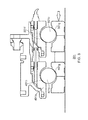
- Figure 1 shows a half-section of a portion of a bearing housing 101 of a gas turbine engine.
- the engine is a three-shaft gas turbine engine of an aircraft.
- a shaft 201 of the engine extends through the generally-annular bearing housing 101 and is supported by a location bearing arrangement 301.
- the shaft connects a high pressure turbine and a high pressure compressor (not shown) of the engine.
- the location bearing arrangement 301 comprises first and second bearings 401, 501, each of which includes an inner race 401 a, 501 a and an outer race 401 b, 501 b, between which a plurality of rolling elements 401 c, 501 c is disposed in a cage (not shown).
- the rolling elements 401 c, 501 c are balls.
- each of the first and second bearings 401, 501 is a single-row bearing of the deep-groove type.
- the inner races 401 a, 501 a and the outer races 401 b, 501 b comprise M50NiL steel and the rolling elements 401 c, 501 c comprise M50 steel.
- the inner races 401 a, 501 a of the first and second bearings 401, 501 are mounted on the shaft 201 and are separated by an axial gap 601 which has an axial dimension of 5 mm.
- a spacer 603 is disposed in the axial gap 601, as will be discussed further herein below.
- the inner races 401 a, 501 a are in fixed axial relationship with one another and with the shaft 201.
- each of the outer races 401 b, 501 b comprises an axial end surface, or pressure face 401 d, 501 d.
- the outer races 401 b, 501 b of the first and second bearings 401, 501 are free to slide axially within the bearing housing 101.
- seals 701 are disposed between each of the outer races 401 b, 501 b and the bearing housing 101.
- the first and second bearings 401, 501 include stops 401 e, 501 e for limiting their axial travel relative to the bearing housing 101.
- a cavity 801 is provided between the first and second bearings 401, 501 and the inner surface of the bearing housing 101.
- the cavity 801 comprises a first cavity space, or chamber 801 a adjacent (coincident with) the pressure surface 401 d of the first bearing 401 and bounded by a first support element 101 a of the bearing housing 101.
- the cavity 801 further comprises a second cavity space, or chamber 801 b adjacent (coincident with) the pressure surface 501 d of the second bearing 501 and bounded by a second support element 101 b of the bearing housing 101.
- the first and second support elements 101 a, 101 b are generally cone-shaped.
- first and second chambers 801 a, 801 b are connected by a conduit, or passage 801 c.
- the passage 801 c extends through the outer races 401 b, 501 b of the first and second bearings 401, 501, and also through an axially-movable communication duct 801 d which connects the first and second chambers 801a, 801b.
- the cavity 801 contains a substantially non-compressible fluid, in this embodiment a liquid, in particular an oil 801 e.
- the seals 701 prevent the oil 801 e from escaping from the cavity 801.
- the fluid-containing cavity 801 comprises a reservoir which hydraulically connects the first and second bearings 401, 501, and in particular provides a hydraulic path between the respective first and second pressure faces 401 d, 501 d thereof.
- a portion of a pressure sensor 901 is disposed in the passage 801 c such that the pressure of the oil 801 e therein may be detected.
- each of the first and second bearings 401, 501 there exists a clearance gap 401 f, 501f between the rolling elements 401 c, 501 c, and the inner race 401 a, 501 a and the outer race 401 b, 501 b.
- the clearance gaps 401 f, 501f provide free "play" or axial in the first and second bearings 401, 501.
- the clearance gap 401f in the first bearing 401 has a maximum size of 1.00 mm and the clearance gap 501f in the second bearing 501 has a maximum size of 1.01 mm.
- the shaft 201 is being driven by the high pressure turbine to rotate about its longitudinal axis.
- the shaft 201 is moving axially (from right to left as indicated by the arrow), relative to the static bearing housing 101, under a net aerodynamic force between the high pressure turbine and the high pressure compressor.
- the inner races 401 a, 501 a of the first and second bearings 401, 501 (which in this embodiment are mounted to the shaft 201 and are in fixed axial relationship there with) come into contact with the respective rolling elements 401 c, 501 c at respective contact points 401 g, 501 g.
- the rolling elements 401 c come into contact with the outer race 401 b at contact points 401 h.
- an axial thrust load is exerted on, and transmitted through, the first bearing 401 by the shaft 201. Due to the aforementioned difference in the size of the clearance gaps 401f, 501f in the first and second bearings 401, 501, the clearance gap 501f of the second bearing 501 is not yet closed but is reduced in size (to 10 microns).
- the (10 micron) clearance gap 501f in the second bearing 501 is closed as the rolling elements 501 c of the second bearing 501 are brought into contact with the respective outer race 501 b at contact points 501 h.
- the axial movement of the first bearing 401 enables the second bearing 501 to take up a share of the axial thrust load imposed by the shaft 201.
- the second bearing 501 may be sufficiently loaded that skidding of its rolling elements 501 c may be prevented.
- the axial thrust load is transmitted to the oil 801e in the first chamber 801 a via the pressure face 401 d of the outer race 401 b of the first bearing 401. Since the oil 801 e is substantially non-compressible, some portion of the oil 801 e is displaced, from the first chamber 801 a into the second chamber 801 b, via the passage 801 c (from left to right in Figure 4 as indicated by the arrows). That is, at least some of the oil 801e is transferred in the axial direction from the first bearing 401 to the second bearing 501.
- the displaced oil 801e exerts a reaction force, on the pressure face 501 d of the outer race 501 b of the second bearing 501, to increase the load on the second bearing 501.
- the axial thrust load is substantially equally shared between the first and second bearings 401, 501.
- the ability of the hydraulic connection to distribute the axial thrust load between the first and second bearings 401, 501 means that relatively large geometrical variations and/or differential expansions between the bearings 401, 501 may be tolerated. Furthermore, the provision of a non-compressible fluid means that the loads imposed on the first and second bearings 401, 501 may be conveniently and reliably derived from pressure measurements taken by the sensor 901. Knowledge of these loads can be exploited by the engine operator to better predict the service life of the bearings 401, 501, which knowledge can in turn be fed back to the design process to improve the design of the bearings 401, 501.
- the thickness T of the spacer 603 is selected to be sufficient to bring the rolling elements 401 c, 501 c of each of the first and second bearings 401, 501 into engagement with the respective inner races 401 a, 501 a at contact points 401 g, 501g and the respective outer races 401 b, 501 b at contact points 401 h, 501 h. That is, the spacer 603 ensures the closure (or at least part-closure) of the clearance gaps 401f, 501f to take up the free play or axial float in the first and second bearings 401, 501, prior to the application of a significant thrust load from the shaft 201 during engine operation.
- the spacer 603 may ensure that some load is maintained on the bearings 401, 501 in the event of a hydraulic failure. It will be understood that while the spacer 603 may optionally be employed to take up the free play or axial float in the first and second bearings 401, 501, the spacer 603 is not necessary for the hydraulic load share function of the bearing arrangement 301 as described herein above.
- each of the support elements 101 a, 101b of the bearing housing 101, which bound the respective first and second chambers 801 a, 801 b of the cavity 801, comprises a flexible or resilient element, for example a diaphragm, which is arranged to be displaced or deformed under the axial thrust load imposed by the shaft 201 so that the bearings 401, 501 may be axially displaced. In this way, the bearings 401, 501 may remain loaded, and the load shared between the bearings 401, 501, even in the event of a loss of hydraulic fluid.
- the inner races 401 a, 501 a are disposed on the shaft 201 such that the first and second bearings 401, 501 are far apart.
- the axial spacing between the first and second thrust bearings 401, 501 is no particular limit to the axial spacing between the first and second thrust bearings 401, 501, other than with regard to practical tolerances and thermal expansion which will increase with distance.
- the axial gap 601 has an axial dimension of anything up to about 25 mm, while in other embodiments the axial dimension exceeds 25 mm.
- the bearings 401, 501 could be separated such that they are in different respective bearing housings, so long as the hydraulic connection is provided between the bearings 401, 501.
- the inner races are made integral with the shaft, for example machined on the shaft 201. Furthermore, it will be understood that it is not essential to the load sharing function of the bearing arrangement 301 that an axial gap 603 is provided between the inner races 401 a, 501 a of the first and second bearings 401, 501.
- bearing arrangement 301 described herein above comprises ball-type roller bearings
- the invention is generally applicable to all types of bearings which take a thrust load.
- roller bearings comprising inclined or tapered cylindrical rolling elements, and hydrostatic or hydrodynamic thrust bearings.
- the invention is not limited to embodiments comprising two thrust bearings but may comprise any number of thrust bearings, for example three or four thrust bearings.
- the pressure faces of the first and second bearings are of dissimilar surface area such that they transmit different magnitudes of force, thereby providing unequal load share between the first and second bearings.
- the pressure faces may be differently sized in order to achieve a load share of 60:40.
- the bearings could be hydraulically connected in various different ways, so long as a non-compressible fluid may be displaced by a load which is exerted on the fluid by the first bearing, and the fluid may exert a reaction force on the second bearing, in order that the load is shared between the first and second bearings.
- the non-compressible fluid need not be in direct contact with the respective pressure faces of the first and second bearings in order for the load to be shared between the bearings.
- the applied load may be transmitted to, and the reaction force may be transmitted from, the non-compressible fluid via some intermediary element, for example a spacer.
- the non-compressible fluid is a gel or a grease, for example a high-temperature grease.
- the invention is equally applicable to a two-shaft or a single-shaft gas turbine engine.
- the invention is appropriate for gas turbine engines used for other purposes than to power an aircraft, for example industrial gas turbine engines or marine gas turbine engines.
- the invention is not only relevant to gas turbine engines but has wider utility.
- the invention is suitable for application in any rotor, for example of a type used in oil and gas drilling, where an axial load is close to or beyond the capabilities of a single bearing.
Landscapes
- Engineering & Computer Science (AREA)
- General Engineering & Computer Science (AREA)
- Mechanical Engineering (AREA)
- Support Of The Bearing (AREA)
- Rolling Contact Bearings (AREA)
- Magnetic Bearings And Hydrostatic Bearings (AREA)
Abstract
Description
- The present invention relates to a bearing arrangement, in particular a load sharing bearing arrangement.
- Rotating shafts, such as those used in gas turbine engines, typically require bearings to support relatively moving or rotating components. Where light weight and minimum power loss from friction are required, roller element bearings are common and may be used to react both radial and thrust loads.
- Since single bearings inevitably have a limited thrust capability, two or more bearings may be arranged adjacent one another to share the thrust load. In these so-called "stacked" bearing arrangements, small variations (of the order of a few microns in some cases) in the geometry of the sets of rolling elements or bearing races between the bearings can lead to one bearing taking more of the load than the other(s). Furthermore, under-loading of one set of rolling elements may result in "skidding" of that set, which may cause damage, debris release and bearing failure. For these reasons, the geometry of the rolling elements and bearing races of the different bearings needs to be carefully controlled and matched so that the load may be shared (ideally equally) between the bearings. This requirement to precision-engineer and match bearings in pairs (or other multiples) incurs costs in the manufacturing and supply chain.
- Furthermore, the materials of the rolling elements and/or bearing races may expand in use due to heating, which can exacerbate further the geometrical variations and lead to a "runaway" effect in which one bearing takes progressively more of the load, potentially resulting in bearing failure. This may occur even if matched bearings are selected and installed because even very small geometrical variations between the bearings may be magnified under the severe environmental operating conditions in gas turbine engines.
- In addition, it is difficult or even impossible for the engine operator to determine the loads imposed on the bearings in operation, leading to uncertainty with regard to service life and maintenance schedules.
- It is an object of the invention to alleviate the problems of the prior art at least to some extent.
- The invention is set out in the accompanying claims.
- According to an aspect, there is provided a bearing arrangement, comprising: first and second thrust bearings, arranged on a shaft and including respective first and second pressure faces; and a hydraulic connection, connecting the first and second thrust bearings and comprising a non-compressible fluid; wherein applying a shaft thrust load axially moves the first thrust bearing so that the first pressure face displaces the non-compressible fluid from the first thrust bearing to the second thrust bearing so as to apply a reaction force to the second pressure face, in order that the thrust load is shared between the first and second thrust bearings.
- The hydraulic connection enables the axial thrust load to be shared between the first and second thrust bearings, such that geometrical variations and/or differential expansions between the thrust bearings may be tolerated. Hence, the requirement for careful control and matching of bearings is eliminated, or at least relaxed.
- The non-compressible fluid may comprise a gel, a grease, or a liquid, for example an oil.
- The hydraulic connection may comprise first and second cavity spaces between the respective first and second thrust bearings and a surrounding component, the first and second cavity spaces being coincident with the respective first and second pressure faces and connected to one another, optionally by a passage which extends through outer races of the first and second thrust bearings.
- The first and second cavity spaces may be bounded by resilient elements of the surrounding component, the resilient elements being arranged to allow axial displacement of the thrust bearings in order to share the thrust load between the thrust bearings in the event of a failure of the hydraulic connection.
- The first and second pressure faces may have substantially the same surface area such that the thrust load is substantially equally shared between the first and second thrust bearings. Or, the first and second pressure faces may have substantially different surface area such that the thrust load is unequally shared between the first and second thrust bearings.
- The bearing arrangement may include a sensor arranged to detect the pressure of the non-compressible fluid.
- The first and second thrust bearings may be axially spaced on the shaft. A spacer element may be disposed between the first and second thrust bearings to define the axial distance there between.
- The bearing arrangement may comprise three or more hydraulically-connected thrust bearings. The thrust bearings may be ball bearings, tapered cylindrical roller bearings, hydrostatic bearings, or hydrodynamic bearings.
- According to another aspect, there is provided a gas turbine engine, comprising a bearing arrangement as described herein above.
- According to another aspect, there is provided a bearing arrangement, comprising: first and second thrust bearings, disposed on a shaft and including respective first and second pressure faces; and a hydraulic connection, connecting the first and second thrust bearings and comprising a non-compressible fluid; wherein applying a shaft thrust load axially displaces the first thrust bearing so that the first pressure face exerts a force on the non-compressible fluid, and the said force causes the non-compressible fluid to be displaced between the first and second thrust bearings to exert a reaction force on the second pressure face, in order that the thrust load is shared between the first and second thrust bearings.
- Embodiments of the invention will now be described by way of example, with reference to the accompanying figures in which:
-
Figures 1 and2 are schematic illustrations of a bearing arrangement according to the invention, in an unloaded condition; -
Figure 3 shows the bearing arrangement ofFigure 1 in a part-loaded condition;
and -
Figure 4 shows the bearing arrangement ofFigure 1 in a loaded condition. -
Figure 1 shows a half-section of a portion of a bearinghousing 101 of a gas turbine engine. In this embodiment, the engine is a three-shaft gas turbine engine of an aircraft. Ashaft 201 of the engine extends through the generally-annular bearinghousing 101 and is supported by a location bearingarrangement 301. In this embodiment, the shaft connects a high pressure turbine and a high pressure compressor (not shown) of the engine. - In this embodiment, the location bearing
arrangement 301 comprises first andsecond bearings inner race outer race rolling elements rolling elements second bearings inner races outer races rolling elements - Referring now to
Figure 2 , in this embodiment, theinner races second bearings shaft 201 and are separated by anaxial gap 601 which has an axial dimension of 5 mm. In this embodiment, aspacer 603 is disposed in theaxial gap 601, as will be discussed further herein below. In this embodiment, theinner races shaft 201. In this embodiment, each of theouter races pressure face - The
outer races second bearings housing 101. In this embodiment,seals 701 are disposed between each of theouter races housing 101. In this embodiment, the first andsecond bearings stops housing 101. - A cavity 801 is provided between the first and
second bearings housing 101. In this embodiment, the cavity 801 comprises a first cavity space, orchamber 801 a adjacent (coincident with) thepressure surface 401 d of the first bearing 401 and bounded by afirst support element 101 a of thebearing housing 101. The cavity 801 further comprises a second cavity space, or chamber 801 b adjacent (coincident with) thepressure surface 501 d of the second bearing 501 and bounded by a second support element 101 b of thebearing housing 101. In this embodiment, the first andsecond support elements 101 a, 101 b are generally cone-shaped. In this embodiment, the first andsecond chambers 801 a, 801 b are connected by a conduit, orpassage 801 c. In this embodiment, thepassage 801 c extends through theouter races second bearings second chambers 801a, 801b. - The cavity 801 contains a substantially non-compressible fluid, in this embodiment a liquid, in particular an
oil 801 e. Theseals 701 prevent theoil 801 e from escaping from the cavity 801. Thus the fluid-containing cavity 801 comprises a reservoir which hydraulically connects the first andsecond bearings - In this embodiment, a portion of a
pressure sensor 901 is disposed in thepassage 801 c such that the pressure of theoil 801 e therein may be detected. - In each of the first and
second bearings clearance gap rolling elements inner race outer race Figures 1 and2 ) theclearance gaps second bearings clearance gap 401f in the first bearing 401 has a maximum size of 1.00 mm and theclearance gap 501f in the second bearing 501 has a maximum size of 1.01 mm. That is, there is a difference of 10 microns between theclearance gaps second bearings clearance gaps - The operation of the location bearing
arrangement 301 will now be described, at first with particular reference toFigure 3 . Theshaft 201 is being driven by the high pressure turbine to rotate about its longitudinal axis. In addition, theshaft 201 is moving axially (from right to left as indicated by the arrow), relative to thestatic bearing housing 101, under a net aerodynamic force between the high pressure turbine and the high pressure compressor. As theshaft 201 slides axially theinner races second bearings 401, 501 (which in this embodiment are mounted to theshaft 201 and are in fixed axial relationship there with) come into contact with the respective rollingelements respective contact points shaft 201 continues to slide, in thefirst bearing 401 the rollingelements 401 c come into contact with theouter race 401 b atcontact points 401 h. Thus, an axial thrust load is exerted on, and transmitted through, thefirst bearing 401 by theshaft 201. Due to the aforementioned difference in the size of theclearance gaps second bearings clearance gap 501f of thesecond bearing 501 is not yet closed but is reduced in size (to 10 microns). - Referring now to
Figure 4 , at a certain magnitude the force exerted at the contact points 401 g, by the rollingelements 401 c on theouter race 401 b of thefirst bearing 401, is sufficient to overcome the friction resistance of theseals 701, and theouter race 401 b of the first thrust bearing 401 is axially displaced along with the moving shaft 201 (leftwards as shown inFigure 4 ). - At the same time, the (10 micron)
clearance gap 501f in thesecond bearing 501 is closed as the rollingelements 501 c of thesecond bearing 501 are brought into contact with the respectiveouter race 501 b atcontact points 501 h. Thus, the axial movement of thefirst bearing 401 enables thesecond bearing 501 to take up a share of the axial thrust load imposed by theshaft 201. In this condition, thesecond bearing 501 may be sufficiently loaded that skidding of itsrolling elements 501 c may be prevented. - Still referring to
Figure 4 , as theshaft 201 continues to slide (leftwards), the axial thrust load is transmitted to theoil 801e in thefirst chamber 801 a via thepressure face 401 d of theouter race 401 b of thefirst bearing 401. Since theoil 801 e is substantially non-compressible, some portion of theoil 801 e is displaced, from thefirst chamber 801 a into the second chamber 801 b, via thepassage 801 c (from left to right inFigure 4 as indicated by the arrows). That is, at least some of theoil 801e is transferred in the axial direction from thefirst bearing 401 to thesecond bearing 501. The displacedoil 801e exerts a reaction force, on thepressure face 501 d of theouter race 501 b of thesecond bearing 501, to increase the load on thesecond bearing 501. In this way, the axial thrust load is substantially equally shared between the first andsecond bearings - It will be understood that the
bearing arrangement 301 will behave in the same way if the axial thrust load is applied in the opposite direction to that described herein above, i.e. from left to right inFigures 3 and4 . - The ability of the hydraulic connection to distribute the axial thrust load between the first and
second bearings bearings second bearings sensor 901. Knowledge of these loads can be exploited by the engine operator to better predict the service life of thebearings bearings - In the embodiment described herein above, the
spacer 603, which is disposed in theaxial gap 601 between theinner races second bearings bearing arrangement 301, after installation on theshaft 201 of theinner race 401 a of thefirst bearing 401 and prior to installation on theshaft 201 of theinner race 501 a of thesecond bearing 501. The thickness T of thespacer 603 is selected to be sufficient to bring the rollingelements second bearings inner races contact points outer races contact points spacer 603 ensures the closure (or at least part-closure) of theclearance gaps second bearings shaft 201 during engine operation. In this way, the likelihood of skidding of unloaded (or lightly loaded)bearings spacer 603 may ensure that some load is maintained on thebearings spacer 603 may optionally be employed to take up the free play or axial float in the first andsecond bearings spacer 603 is not necessary for the hydraulic load share function of thebearing arrangement 301 as described herein above. - In an embodiment, each of the
support elements 101 a, 101b of the bearinghousing 101, which bound the respective first andsecond chambers 801 a, 801 b of the cavity 801, comprises a flexible or resilient element, for example a diaphragm, which is arranged to be displaced or deformed under the axial thrust load imposed by theshaft 201 so that thebearings bearings bearings - In an embodiment, the
inner races shaft 201 such that the first andsecond bearings second thrust bearings axial gap 601 has an axial dimension of anything up to about 25 mm, while in other embodiments the axial dimension exceeds 25 mm. Thebearings bearings - In an embodiment, the inner races are made integral with the shaft, for example machined on the
shaft 201. Furthermore, it will be understood that it is not essential to the load sharing function of thebearing arrangement 301 that anaxial gap 603 is provided between theinner races second bearings - While the
bearing arrangement 301 described herein above comprises ball-type roller bearings, it will be understood that the invention is generally applicable to all types of bearings which take a thrust load. For example, roller bearings comprising inclined or tapered cylindrical rolling elements, and hydrostatic or hydrodynamic thrust bearings. Furthermore, it will be understood that the invention is not limited to embodiments comprising two thrust bearings but may comprise any number of thrust bearings, for example three or four thrust bearings. - In an embodiment, the pressure faces of the first and second bearings are of dissimilar surface area such that they transmit different magnitudes of force, thereby providing unequal load share between the first and second bearings. For example, the pressure faces may be differently sized in order to achieve a load share of 60:40.
- While the above-described embodiment comprises a reservoir, in which a passage extends through bearing outer races to connect two chambers, it will be understood that the bearings could be hydraulically connected in various different ways, so long as a non-compressible fluid may be displaced by a load which is exerted on the fluid by the first bearing, and the fluid may exert a reaction force on the second bearing, in order that the load is shared between the first and second bearings. Furthermore, the non-compressible fluid need not be in direct contact with the respective pressure faces of the first and second bearings in order for the load to be shared between the bearings. For instance, the applied load may be transmitted to, and the reaction force may be transmitted from, the non-compressible fluid via some intermediary element, for example a spacer.
- In an embodiment, the non-compressible fluid is a gel or a grease, for example a high-temperature grease.
- It will be understood that the invention has been described in relation to its preferred embodiments and may be modified in many different ways without departing from the scope of the invention as defined by the accompanying claims.
- Although a bearing arrangement in a three-shaft gas turbine engine has been described, the invention is equally applicable to a two-shaft or a single-shaft gas turbine engine. As will be apparent to the skilled reader, the invention is appropriate for gas turbine engines used for other purposes than to power an aircraft, for example industrial gas turbine engines or marine gas turbine engines. Furthermore, the invention is not only relevant to gas turbine engines but has wider utility. The invention is suitable for application in any rotor, for example of a type used in oil and gas drilling, where an axial load is close to or beyond the capabilities of a single bearing.
Claims (14)
- A bearing arrangement (301), comprising:first and second thrust bearings (401, 501), arranged on a shaft (201) and including respective first and second pressure faces (401 d, 501 d); anda hydraulic connection (801), connecting the first and second thrust bearings and comprising a non-compressible fluid;wherein applying a shaft thrust load axially moves the first thrust bearing so that the first pressure face displaces the non-compressible fluid from the first thrust bearing to the second thrust bearing so as to apply a reaction force to the second pressure face, in order that the thrust load is shared between the first and second thrust bearings.
- A bearing arrangement (301) according to claim 1, wherein the non-compressible fluid comprises a gel, a grease, or a liquid, for example an oil (801 e).
- A bearing arrangement (301) according to claim 1 or 2, wherein the hydraulic connection (801) comprises first and second cavity spaces (801 a, 801 b) between the respective first and second thrust bearings (401, 501) and a surrounding component (101), the first and second cavity spaces being coincident with the respective first and second pressure faces (401 d, 501 d) and connected to one another.
- A bearing arrangement (301) according to claim 3, wherein the first and second cavity spaces (801 a, 801 b) are connected to one another by a passage (801 c) which extends through outer races (401 b, 501 b) of the first and second thrust bearings (401, 501).
- A bearing arrangement (301) according to claim 3 or 4, wherein the first and second cavity spaces (801 a, 801 b) are bounded by resilient elements (101 a, 101 b) of the surrounding component (101), the resilient elements being arranged to deform to allow axial displacement of the thrust bearings (401, 501) in order to share the thrust load between the thrust bearings in the event of a failure of the hydraulic connection (801).
- A bearing arrangement (301) according to any of claims 1 to 5, wherein the first and second pressure faces (401 d, 501 d) have substantially the same surface area such that the thrust load is substantially equally shared between the first and second thrust bearings (401, 501).
- A bearing arrangement (301) according to any of claims 1 to 5, wherein the first and second pressure faces (401 d, 501 d) have substantially different surface area such that the thrust load is unequally shared between the first and second thrust bearings (401, 501).
- A bearing arrangement (301) according to any of claims 1 to 7, including a sensor (901) arranged to detect the pressure of the non-compressible fluid.
- A bearing arrangement (301) according to any of claims 1 to 8, wherein the first and second thrust bearings (401, 501) are axially spaced on the shaft (201).
- A bearing arrangement (301) according to claim 9, including a spacer element (603) which is disposed between the first and second thrust bearings (401, 501) to define the axial distance there between.
- A bearing arrangement (301) according to any of claims 1 to 10, comprising three or more hydraulically-connected thrust bearings.
- A bearing arrangement (301) according to any of claims 1 to 11, wherein the thrust bearings are ball bearings, tapered cylindrical roller bearings, hydrostatic bearings, or hydrodynamic bearings.
- A gas turbine engine, comprising a bearing arrangement (301) according to any of claims 1 to 12.
- A bearing arrangement (301), comprising:first and second thrust bearings (401, 501), disposed on a shaft (201) and including respective first and second pressure faces (401 d, 501 d); anda hydraulic connection (801), connecting the first and second thrust bearings and comprising a non-compressible fluid;wherein applying a shaft thrust load axially displaces the first thrust bearing so that the first pressure face exerts a force on the non-compressible fluid, and the said force causes the non-compressible fluid to be displaced between the first and second thrust bearings to exert a reaction force on the second pressure face, in order that the thrust load is shared between the first and second thrust bearings.
Applications Claiming Priority (1)
| Application Number | Priority Date | Filing Date | Title |
|---|---|---|---|
| GBGB1404875.5A GB201404875D0 (en) | 2014-03-19 | 2014-03-19 | Bearing arrangement |
Publications (2)
| Publication Number | Publication Date |
|---|---|
| EP2921729A2 true EP2921729A2 (en) | 2015-09-23 |
| EP2921729A3 EP2921729A3 (en) | 2015-12-30 |
Family
ID=50635004
Family Applications (1)
| Application Number | Title | Priority Date | Filing Date |
|---|---|---|---|
| EP15156323.6A Withdrawn EP2921729A3 (en) | 2014-03-19 | 2015-02-24 | Bearing arrangement |
Country Status (3)
| Country | Link |
|---|---|
| US (1) | US9651092B2 (en) |
| EP (1) | EP2921729A3 (en) |
| GB (1) | GB201404875D0 (en) |
Cited By (3)
| Publication number | Priority date | Publication date | Assignee | Title |
|---|---|---|---|---|
| EP3040568A1 (en) * | 2014-12-09 | 2016-07-06 | Rolls-Royce plc | Bearing structure with two juxtaposed rolling bearings and a pressure chamber with a resilient wall for preloading the bearings and for equalising the axial load on the two bearings |
| US9447817B2 (en) | 2014-12-09 | 2016-09-20 | Rolls-Royce Plc | Bearing structure |
| EP3816411A1 (en) * | 2019-11-01 | 2021-05-05 | Pratt & Whitney Canada Corp. | Flanged integral piston bearing |
Families Citing this family (7)
| Publication number | Priority date | Publication date | Assignee | Title |
|---|---|---|---|---|
| GB2546989B (en) | 2016-02-03 | 2018-08-29 | Rolls Royce Plc | Bearing arrangements |
| US10458185B2 (en) | 2017-01-05 | 2019-10-29 | Baker Hughes, A Ge Company, Llc | Mud motors with thrust bearing with enhanced torque |
| JP7362239B2 (en) * | 2018-02-13 | 2023-10-17 | Ntn株式会社 | Bearing devices and spindle devices |
| US11453487B2 (en) * | 2018-06-28 | 2022-09-27 | Sikorsky Aircraft Corporation | Redundant helicopter pitch change bearing |
| EP4321736A1 (en) * | 2022-08-12 | 2024-02-14 | Unison Industries, LLC | Air turbine starter with bearing support structure |
| JP7831228B2 (en) * | 2022-11-02 | 2026-03-17 | 日本精工株式会社 | Bearing device |
| CN119957605B (en) * | 2025-01-13 | 2026-01-23 | 中国船舶集团有限公司第七一一研究所 | Thrust structure and its design method and engine |
Family Cites Families (14)
| Publication number | Priority date | Publication date | Assignee | Title |
|---|---|---|---|---|
| US3580649A (en) * | 1968-08-15 | 1971-05-25 | Matsushita Electric Industrial Co Ltd | High thrust bearing apparatus |
| CH503901A (en) * | 1969-12-30 | 1971-02-28 | Von Roll Ag | Axial piston unit |
| FR2110693A5 (en) | 1970-10-27 | 1972-06-02 | Snecma | |
| GB1458660A (en) * | 1972-09-13 | 1976-12-15 | Glacier Metal Co Ltd | Thrust balancer device |
| CH633355A5 (en) | 1978-08-04 | 1982-11-30 | Bbc Brown Boveri & Cie | AXLE BEARING BEARING ARRANGEMENT. |
| JPH0540273Y2 (en) | 1988-04-26 | 1993-10-13 | ||
| JPH0830501B2 (en) | 1988-06-07 | 1996-03-27 | 日産自動車株式会社 | Bearing fixing device |
| US6082907A (en) * | 1995-03-31 | 2000-07-04 | Andritz Inc. | Pre-loading device for a radical-bearing unit |
| DE10126103C2 (en) * | 2001-05-29 | 2003-02-06 | Leico Werkzeugmaschb Gmbh & Co | bearing arrangement |
| DE10346647A1 (en) * | 2003-10-08 | 2005-05-25 | Ritz Pumpenfabrik Gmbh & Co. Kg | Axial bearing system for underwater pumps comprises two rocker-segment bearings fitted with pressure equalizing system consisting of two hydraulic pressure chambers which are connected by e.g. by pressure equalizing tube |
| GB0720628D0 (en) | 2007-10-20 | 2007-11-28 | Rolls Royce Plc | Bearing arrangement |
| US7987913B2 (en) * | 2008-09-26 | 2011-08-02 | Baker Hughes Incorporated | Electrical submersible pump with equally loaded thrust bearings and method of pumping subterranean fluid |
| GB0822245D0 (en) | 2008-12-08 | 2009-01-14 | Rolls Royce Plc | A bearing arrangement |
| DE102011086675A1 (en) | 2011-11-18 | 2013-05-23 | Rolls-Royce Deutschland Ltd & Co Kg | Storage device and turbomachinery with storage device |
-
2014
- 2014-03-19 GB GBGB1404875.5A patent/GB201404875D0/en not_active Ceased
-
2015
- 2015-02-24 EP EP15156323.6A patent/EP2921729A3/en not_active Withdrawn
- 2015-02-25 US US14/631,180 patent/US9651092B2/en active Active
Cited By (6)
| Publication number | Priority date | Publication date | Assignee | Title |
|---|---|---|---|---|
| EP3040568A1 (en) * | 2014-12-09 | 2016-07-06 | Rolls-Royce plc | Bearing structure with two juxtaposed rolling bearings and a pressure chamber with a resilient wall for preloading the bearings and for equalising the axial load on the two bearings |
| US9447817B2 (en) | 2014-12-09 | 2016-09-20 | Rolls-Royce Plc | Bearing structure |
| US9829037B2 (en) | 2014-12-09 | 2017-11-28 | Rolls-Royce Plc | Bearing structure |
| EP3816411A1 (en) * | 2019-11-01 | 2021-05-05 | Pratt & Whitney Canada Corp. | Flanged integral piston bearing |
| US20210131306A1 (en) * | 2019-11-01 | 2021-05-06 | Pratt & Whitney Canada Corp. | Flanged integral piston bearing |
| US11021994B2 (en) * | 2019-11-01 | 2021-06-01 | Pratt & Whitney Canada Corp. | Flanged integral piston bearing |
Also Published As
| Publication number | Publication date |
|---|---|
| EP2921729A3 (en) | 2015-12-30 |
| US20150267745A1 (en) | 2015-09-24 |
| US9651092B2 (en) | 2017-05-16 |
| GB201404875D0 (en) | 2014-04-30 |
Similar Documents
| Publication | Publication Date | Title |
|---|---|---|
| US9651092B2 (en) | Bearing arrangement | |
| US9658132B2 (en) | Bearing arrangement and method | |
| Hong et al. | Rolling-element bearing modeling: A review | |
| US9366295B2 (en) | Rolling bearing assembly | |
| US4641978A (en) | Bearing system | |
| US5145189A (en) | Hydro-lift dynamic circumferential seal | |
| CA2509931C (en) | Compliant support for increased load capacity axial thrust bearing | |
| US3854781A (en) | Combined hydrostatic bearing and rolling bearing | |
| CN106969030B (en) | Tensioning device and method for preloading bearings | |
| US9512874B2 (en) | Bearing device and turbomachine having a bearing device | |
| EP3159560A1 (en) | Bearing with drained race and squeeze film damper | |
| CN104632879B (en) | Bearing Units for Fluid Machinery Applications | |
| CN109072884B (en) | Wind turbine comprising a moment bearing | |
| CN104011335A (en) | Series bearing support apparatus for a gas turbine engine | |
| EP3511588B1 (en) | Sealed bearing | |
| EP3040568B1 (en) | Bearing structure with two juxtaposed rolling bearings and a pressure chamber with a resilient wall for preloading the bearings and for equalising the axial load on the two bearings | |
| US3158413A (en) | Bearing assembly | |
| CN105121871B (en) | Double-row roller bearing and method for using double-row roller bearing | |
| EP1302636B1 (en) | Rotatably supporting device for turbocharger | |
| US8540432B2 (en) | Disengageable axial abutment | |
| US9062711B2 (en) | Bearing assembly | |
| US8858087B2 (en) | Bearing assembly | |
| Slaney | Hybrid ceramic bearing development for gas turbine engines | |
| CN108463641B (en) | Asymmetric ball bearing system for a turbocharger | |
| CN111322314A (en) | Roller bearing with lubrication channel |
Legal Events
| Date | Code | Title | Description |
|---|---|---|---|
| PUAI | Public reference made under article 153(3) epc to a published international application that has entered the european phase |
Free format text: ORIGINAL CODE: 0009012 |
|
| AK | Designated contracting states |
Kind code of ref document: A2 Designated state(s): AL AT BE BG CH CY CZ DE DK EE ES FI FR GB GR HR HU IE IS IT LI LT LU LV MC MK MT NL NO PL PT RO RS SE SI SK SM TR |
|
| AX | Request for extension of the european patent |
Extension state: BA ME |
|
| PUAL | Search report despatched |
Free format text: ORIGINAL CODE: 0009013 |
|
| AK | Designated contracting states |
Kind code of ref document: A3 Designated state(s): AL AT BE BG CH CY CZ DE DK EE ES FI FR GB GR HR HU IE IS IT LI LT LU LV MC MK MT NL NO PL PT RO RS SE SI SK SM TR |
|
| AX | Request for extension of the european patent |
Extension state: BA ME |
|
| RIC1 | Information provided on ipc code assigned before grant |
Ipc: F16C 19/54 20060101ALI20151126BHEP Ipc: F16C 41/00 20060101ALI20151126BHEP Ipc: F16C 25/08 20060101AFI20151126BHEP Ipc: F16C 39/02 20060101ALI20151126BHEP Ipc: F16C 41/02 20060101ALI20151126BHEP Ipc: F16C 33/58 20060101ALN20151126BHEP |
|
| 17P | Request for examination filed |
Effective date: 20160425 |
|
| RBV | Designated contracting states (corrected) |
Designated state(s): AL AT BE BG CH CY CZ DE DK EE ES FI FR GB GR HR HU IE IS IT LI LT LU LV MC MK MT NL NO PL PT RO RS SE SI SK SM TR |
|
| STAA | Information on the status of an ep patent application or granted ep patent |
Free format text: STATUS: EXAMINATION IS IN PROGRESS |
|
| 17Q | First examination report despatched |
Effective date: 20190128 |
|
| RAP1 | Party data changed (applicant data changed or rights of an application transferred) |
Owner name: ROLLS-ROYCE PLC |
|
| GRAP | Despatch of communication of intention to grant a patent |
Free format text: ORIGINAL CODE: EPIDOSNIGR1 |
|
| STAA | Information on the status of an ep patent application or granted ep patent |
Free format text: STATUS: GRANT OF PATENT IS INTENDED |
|
| INTG | Intention to grant announced |
Effective date: 20200429 |
|
| STAA | Information on the status of an ep patent application or granted ep patent |
Free format text: STATUS: THE APPLICATION IS DEEMED TO BE WITHDRAWN |
|
| 18D | Application deemed to be withdrawn |
Effective date: 20200910 |