EP2921675A1 - Diesel engine control device, diesel engine, and diesel engine control method - Google Patents
Diesel engine control device, diesel engine, and diesel engine control method Download PDFInfo
- Publication number
- EP2921675A1 EP2921675A1 EP13855962.0A EP13855962A EP2921675A1 EP 2921675 A1 EP2921675 A1 EP 2921675A1 EP 13855962 A EP13855962 A EP 13855962A EP 2921675 A1 EP2921675 A1 EP 2921675A1
- Authority
- EP
- European Patent Office
- Prior art keywords
- fuel
- diesel engine
- load
- oil
- gas
- Prior art date
- Legal status (The legal status is an assumption and is not a legal conclusion. Google has not performed a legal analysis and makes no representation as to the accuracy of the status listed.)
- Granted
Links
Images



Classifications
-
- F—MECHANICAL ENGINEERING; LIGHTING; HEATING; WEAPONS; BLASTING
- F02—COMBUSTION ENGINES; HOT-GAS OR COMBUSTION-PRODUCT ENGINE PLANTS
- F02D—CONTROLLING COMBUSTION ENGINES
- F02D41/00—Electrical control of supply of combustible mixture or its constituents
- F02D41/0025—Controlling engines characterised by use of non-liquid fuels, pluralities of fuels, or non-fuel substances added to the combustible mixtures
-
- F—MECHANICAL ENGINEERING; LIGHTING; HEATING; WEAPONS; BLASTING
- F02—COMBUSTION ENGINES; HOT-GAS OR COMBUSTION-PRODUCT ENGINE PLANTS
- F02D—CONTROLLING COMBUSTION ENGINES
- F02D19/00—Controlling engines characterised by their use of non-liquid fuels, pluralities of fuels, or non-fuel substances added to the combustible mixtures
- F02D19/06—Controlling engines characterised by their use of non-liquid fuels, pluralities of fuels, or non-fuel substances added to the combustible mixtures peculiar to engines working with pluralities of fuels, e.g. alternatively with light and heavy fuel oil, other than engines indifferent to the fuel consumed
- F02D19/0602—Control of components of the fuel supply system
- F02D19/0607—Control of components of the fuel supply system to adjust the fuel mass or volume flow
- F02D19/061—Control of components of the fuel supply system to adjust the fuel mass or volume flow by controlling fuel injectors
-
- F—MECHANICAL ENGINEERING; LIGHTING; HEATING; WEAPONS; BLASTING
- F02—COMBUSTION ENGINES; HOT-GAS OR COMBUSTION-PRODUCT ENGINE PLANTS
- F02D—CONTROLLING COMBUSTION ENGINES
- F02D19/00—Controlling engines characterised by their use of non-liquid fuels, pluralities of fuels, or non-fuel substances added to the combustible mixtures
- F02D19/06—Controlling engines characterised by their use of non-liquid fuels, pluralities of fuels, or non-fuel substances added to the combustible mixtures peculiar to engines working with pluralities of fuels, e.g. alternatively with light and heavy fuel oil, other than engines indifferent to the fuel consumed
- F02D19/0663—Details on the fuel supply system, e.g. tanks, valves, pipes, pumps, rails, injectors or mixers
- F02D19/0686—Injectors
- F02D19/0689—Injectors for in-cylinder direct injection
-
- F—MECHANICAL ENGINEERING; LIGHTING; HEATING; WEAPONS; BLASTING
- F02—COMBUSTION ENGINES; HOT-GAS OR COMBUSTION-PRODUCT ENGINE PLANTS
- F02D—CONTROLLING COMBUSTION ENGINES
- F02D19/00—Controlling engines characterised by their use of non-liquid fuels, pluralities of fuels, or non-fuel substances added to the combustible mixtures
- F02D19/06—Controlling engines characterised by their use of non-liquid fuels, pluralities of fuels, or non-fuel substances added to the combustible mixtures peculiar to engines working with pluralities of fuels, e.g. alternatively with light and heavy fuel oil, other than engines indifferent to the fuel consumed
- F02D19/0663—Details on the fuel supply system, e.g. tanks, valves, pipes, pumps, rails, injectors or mixers
- F02D19/0686—Injectors
- F02D19/0692—Arrangement of multiple injectors per combustion chamber
-
- F—MECHANICAL ENGINEERING; LIGHTING; HEATING; WEAPONS; BLASTING
- F02—COMBUSTION ENGINES; HOT-GAS OR COMBUSTION-PRODUCT ENGINE PLANTS
- F02D—CONTROLLING COMBUSTION ENGINES
- F02D19/00—Controlling engines characterised by their use of non-liquid fuels, pluralities of fuels, or non-fuel substances added to the combustible mixtures
- F02D19/06—Controlling engines characterised by their use of non-liquid fuels, pluralities of fuels, or non-fuel substances added to the combustible mixtures peculiar to engines working with pluralities of fuels, e.g. alternatively with light and heavy fuel oil, other than engines indifferent to the fuel consumed
- F02D19/08—Controlling engines characterised by their use of non-liquid fuels, pluralities of fuels, or non-fuel substances added to the combustible mixtures peculiar to engines working with pluralities of fuels, e.g. alternatively with light and heavy fuel oil, other than engines indifferent to the fuel consumed simultaneously using pluralities of fuels
- F02D19/081—Adjusting the fuel composition or mixing ratio; Transitioning from one fuel to the other
-
- F—MECHANICAL ENGINEERING; LIGHTING; HEATING; WEAPONS; BLASTING
- F02—COMBUSTION ENGINES; HOT-GAS OR COMBUSTION-PRODUCT ENGINE PLANTS
- F02D—CONTROLLING COMBUSTION ENGINES
- F02D19/00—Controlling engines characterised by their use of non-liquid fuels, pluralities of fuels, or non-fuel substances added to the combustible mixtures
- F02D19/06—Controlling engines characterised by their use of non-liquid fuels, pluralities of fuels, or non-fuel substances added to the combustible mixtures peculiar to engines working with pluralities of fuels, e.g. alternatively with light and heavy fuel oil, other than engines indifferent to the fuel consumed
- F02D19/08—Controlling engines characterised by their use of non-liquid fuels, pluralities of fuels, or non-fuel substances added to the combustible mixtures peculiar to engines working with pluralities of fuels, e.g. alternatively with light and heavy fuel oil, other than engines indifferent to the fuel consumed simultaneously using pluralities of fuels
- F02D19/10—Controlling engines characterised by their use of non-liquid fuels, pluralities of fuels, or non-fuel substances added to the combustible mixtures peculiar to engines working with pluralities of fuels, e.g. alternatively with light and heavy fuel oil, other than engines indifferent to the fuel consumed simultaneously using pluralities of fuels peculiar to compression-ignition engines in which the main fuel is gaseous
- F02D19/105—Controlling engines characterised by their use of non-liquid fuels, pluralities of fuels, or non-fuel substances added to the combustible mixtures peculiar to engines working with pluralities of fuels, e.g. alternatively with light and heavy fuel oil, other than engines indifferent to the fuel consumed simultaneously using pluralities of fuels peculiar to compression-ignition engines in which the main fuel is gaseous operating in a special mode, e.g. in a liquid fuel only mode for starting
-
- F—MECHANICAL ENGINEERING; LIGHTING; HEATING; WEAPONS; BLASTING
- F02—COMBUSTION ENGINES; HOT-GAS OR COMBUSTION-PRODUCT ENGINE PLANTS
- F02D—CONTROLLING COMBUSTION ENGINES
- F02D31/00—Use of speed-sensing governors to control combustion engines, not otherwise provided for
- F02D31/001—Electric control of rotation speed
- F02D31/007—Electric control of rotation speed controlling fuel supply
-
- F—MECHANICAL ENGINEERING; LIGHTING; HEATING; WEAPONS; BLASTING
- F02—COMBUSTION ENGINES; HOT-GAS OR COMBUSTION-PRODUCT ENGINE PLANTS
- F02B—INTERNAL-COMBUSTION PISTON ENGINES; COMBUSTION ENGINES IN GENERAL
- F02B3/00—Engines characterised by air compression and subsequent fuel addition
- F02B3/06—Engines characterised by air compression and subsequent fuel addition with compression ignition
-
- F—MECHANICAL ENGINEERING; LIGHTING; HEATING; WEAPONS; BLASTING
- F02—COMBUSTION ENGINES; HOT-GAS OR COMBUSTION-PRODUCT ENGINE PLANTS
- F02D—CONTROLLING COMBUSTION ENGINES
- F02D19/00—Controlling engines characterised by their use of non-liquid fuels, pluralities of fuels, or non-fuel substances added to the combustible mixtures
- F02D19/06—Controlling engines characterised by their use of non-liquid fuels, pluralities of fuels, or non-fuel substances added to the combustible mixtures peculiar to engines working with pluralities of fuels, e.g. alternatively with light and heavy fuel oil, other than engines indifferent to the fuel consumed
- F02D19/0639—Controlling engines characterised by their use of non-liquid fuels, pluralities of fuels, or non-fuel substances added to the combustible mixtures peculiar to engines working with pluralities of fuels, e.g. alternatively with light and heavy fuel oil, other than engines indifferent to the fuel consumed characterised by the type of fuels
- F02D19/0642—Controlling engines characterised by their use of non-liquid fuels, pluralities of fuels, or non-fuel substances added to the combustible mixtures peculiar to engines working with pluralities of fuels, e.g. alternatively with light and heavy fuel oil, other than engines indifferent to the fuel consumed characterised by the type of fuels at least one fuel being gaseous, the other fuels being gaseous or liquid at standard conditions
- F02D19/0647—Controlling engines characterised by their use of non-liquid fuels, pluralities of fuels, or non-fuel substances added to the combustible mixtures peculiar to engines working with pluralities of fuels, e.g. alternatively with light and heavy fuel oil, other than engines indifferent to the fuel consumed characterised by the type of fuels at least one fuel being gaseous, the other fuels being gaseous or liquid at standard conditions the gaseous fuel being liquefied petroleum gas [LPG], liquefied natural gas [LNG], compressed natural gas [CNG] or dimethyl ether [DME]
-
- F—MECHANICAL ENGINEERING; LIGHTING; HEATING; WEAPONS; BLASTING
- F02—COMBUSTION ENGINES; HOT-GAS OR COMBUSTION-PRODUCT ENGINE PLANTS
- F02D—CONTROLLING COMBUSTION ENGINES
- F02D41/00—Electrical control of supply of combustible mixture or its constituents
- F02D41/0025—Controlling engines characterised by use of non-liquid fuels, pluralities of fuels, or non-fuel substances added to the combustible mixtures
- F02D41/0027—Controlling engines characterised by use of non-liquid fuels, pluralities of fuels, or non-fuel substances added to the combustible mixtures the fuel being gaseous
-
- F—MECHANICAL ENGINEERING; LIGHTING; HEATING; WEAPONS; BLASTING
- F02—COMBUSTION ENGINES; HOT-GAS OR COMBUSTION-PRODUCT ENGINE PLANTS
- F02D—CONTROLLING COMBUSTION ENGINES
- F02D41/00—Electrical control of supply of combustible mixture or its constituents
- F02D41/30—Controlling fuel injection
- F02D41/3011—Controlling fuel injection according to or using specific or several modes of combustion
- F02D41/3064—Controlling fuel injection according to or using specific or several modes of combustion with special control during transition between modes
-
- Y—GENERAL TAGGING OF NEW TECHNOLOGICAL DEVELOPMENTS; GENERAL TAGGING OF CROSS-SECTIONAL TECHNOLOGIES SPANNING OVER SEVERAL SECTIONS OF THE IPC; TECHNICAL SUBJECTS COVERED BY FORMER USPC CROSS-REFERENCE ART COLLECTIONS [XRACs] AND DIGESTS
- Y02—TECHNOLOGIES OR APPLICATIONS FOR MITIGATION OR ADAPTATION AGAINST CLIMATE CHANGE
- Y02T—CLIMATE CHANGE MITIGATION TECHNOLOGIES RELATED TO TRANSPORTATION
- Y02T10/00—Road transport of goods or passengers
- Y02T10/10—Internal combustion engine [ICE] based vehicles
- Y02T10/30—Use of alternative fuels, e.g. biofuels
Definitions
- the present invention relates to a diesel engine control device, a diesel engine, and a diesel engine control method.
- diesel engines there are known diesel engines (hereinafter, referred to as “dual-fuel diesel engines") in which gas fuel, such as natural gas, is used as main fuel, oil fuel having excellent compression ignition capability is used as pilot fuel, and self-ignition of the oil fuel is caused in a high-temperature combustion chamber, thereby combusting the gas fuel as main fuel. Because the dual-fuel diesel engines use gas fuel, emissions of CO 2 and hazardous substances, such as black smoke, are less during the combustion.
- PTL 1 discloses a dual-fuel diesel engine in which low-cetane fuel having poor compression ignition capability, such as gas fuel, is used as main fuel, and oil fuel having excellent compression ignition capability is used as pilot fuel.
- the engine disclosed in PTL 1 has gas-fuel injection valves and pilot-fuel injection valves that are provided in a cylinder head, gas fuel and pilot fuel are injected from the gas-fuel injection valves and the pilot-fuel injection valves toward a combustion chamber, and self-ignition of the pilot fuel is caused in the high-temperature combustion chamber, thereby combusting the main fuel.
- PTL 1 does not disclose a specific method for supplying oil fuel and gas fuel to the diesel engine. In dual-fuel diesel engines, stable operation using oil fuel and gas fuel is to be achieved.
- the present invention is made in view of such circumstances, and an object thereof is to provide a diesel engine control device, a diesel engine, and a diesel engine control method that are capable of reducing the use of oil fuel and also allowing stable operation using oil fuel and gas fuel.
- a diesel engine control device In order to solve the above-described problem, a diesel engine control device, a diesel engine, and a diesel engine control method of the present invention employ the following solutions.
- a first aspect of the present invention provides a diesel engine control device for a diesel engine that is operated by being supplied with gas fuel and oil fuel, the control device comprising: a governor control unit for performing governor control; and a fuel control unit for reducing a rate of increase of oil fuel supply compared with that before a load of the diesel engine reaches a predetermined value, and for starting gas fuel supply after a certain delay from timing at which the load reaches the predetermined value.
- the diesel engine control device controls the gas fuel supply and the oil fuel supply to the diesel engine. Supplying gas fuel and oil fuel is conducted through governor control by the governor control means. Then, when the load of the diesel engine increases to the predetermined value, the single-fuel combustion, which uses oil fuel, is switched to the multi-fuel combustion, which uses oil fuel and gas fuel.
- Reducing the rate of increase of the oil fuel supply means that the increase in the load becomes slower than before. Then, when the timing at which gas fuel is supplied is delayed, supplying gas fuel is started during the slow increase in the load. Therefore, a situation in which the load increases rapidly due to supplying gas fuel, with chattering, is prevented.
- the fuel control unit reduces the supply of the oil fuel compared with that before the load decreases and reaches the predetermined value and stops supplying the gas fuel after a certain delay from timing at which the load reaches the predetermined value.
- a second aspect of the present invention provides a diesel engine control device for a diesel engine that is operated by being supplied with gas fuel and oil fuel, the control device comprising: a governor control unit for performing governor control; and a fuel control unit for switching from single-fuel combustion using the oil fuel to multi-fuel combustion using the oil fuel and the gas fuel when a load of the diesel engine increases and reaches a first predetermined value, and for switching from the multi-fuel combustion to the single-fuel combustion when the load of the diesel engine decreases and reaches a second predetermined value smaller than the first value.
- the single-fuel combustion which uses oil fuel
- the multi-fuel combustion which uses oil fuel and gas fuel.
- the load of the diesel engine decreases and reaches the second predetermined value, which is smaller than the first load
- the multi-fuel combustion is switched to the single-fuel combustion.
- a third aspect of the present invention provides a diesel engine including: a gas-fuel injection valve that is provided in a combustion chamber and that injects gas fuel; an oil-fuel injection valve that is provided in the combustion chamber and that injects oil fuel; and the above-described control device.
- a fourth aspect of the present invention provides a diesel engine control method for a diesel engine that is operated by being supplied with gas fuel and oil fuel, the control method comprising: a first step of reducing the rate of increase of oil fuel supply compared with that before a load of the diesel engine increases and reaches a predetermined value; and a second step of starting gas fuel supply after a certain delay from timing at which the load decreases and reaches the predetermined value.
- a fifth aspect of the present invention provides a diesel engine control method for a diesel engine that is operated by being supplied with gas fuel and oil fuel, the control method comprising: a first step of switching from single-fuel combustion using the oil fuel to multi-fuel combustion using the oil fuel and the gas fuel when a load of the diesel engine increases and reaches a first predetermined value; and a second step of switching from the multi-fuel combustion to the single-fuel combustion when the load of the diesel engine decreases and reaches a second predetermined value smaller than the first value.
- a diesel engine control device, a diesel engine, and a diesel engine control method according to one embodiment of the present invention will be described below with reference to the drawings.
- a diesel engine according to the first embodiment is a dual-fuel diesel engine that is operated by using gas fuel as main fuel and by using oil fuel as pilot fuel, and is used as a main engine of a ship, for example.
- Fig. 1 is a view showing the configuration of a dual-fuel diesel engine 1 of the first embodiment.
- the dual-fuel diesel engine 1 includes a cylindrical cylinder 2, a cylinder head 3 that is fixed on an upper end of the cylinder 2, and a piston 4 that is movably accommodated in the cylinder 2 so as to move forward and backward.
- a combustion chamber c is formed by a circumferential wall 2a of the cylinder 2, the cylinder head 3, and a top surface 4a of the piston 4.
- reference sign 5 in the figure denotes a piston ring.
- Scavenge ports 6 are open in the circumferential wall 2a at lower portions of the cylinder 2.
- the scavenge ports 6 are formed at positions higher than the top surface 4a (indicated by the two-dot chain line in the figure) of the piston 4 located in the vicinity of a bottom dead position, so that air is supplied from the scavenge ports 6 to the combustion chamber c when the piston 4 is located in the vicinity of the bottom dead position.
- an exhaust port is open, and an exhaust valve 7 that opens and closes the exhaust port is provided at the top of the cylinder head 3.
- the exhaust valve 7 is open until the piston 4 reaches a position which is about 100 degrees before the top dead position, during a scavenging process in which the piston 4 is moving upward. Then, exhaust gas remaining in the combustion chamber c from the prior process is scavenged by air supplied from the scavenge ports 6 to the combustion chamber c.
- the cylinder head 3 is provided with gas-fuel injection valves 8 that inject gas fuel into the combustion chamber c and oil-fuel injection valves 10 that similarly inject oil fuel, which has excellent compression ignition capability, into the combustion chamber c.
- the gas-fuel injection valves 8 are provided at positions that are 180-degree away from each other in the circumferential direction with reference to a cylinder center o serving as the rotation center.
- the oil-fuel injection valves 10 are provided at positions that are 180-degree away from each other in the circumferential direction with reference to the cylinder center o serving as the rotation center.
- the number of the gas-fuel injection valves 8 and the number of the oil-fuel injection valves 10 are not limited and, for example, may be one.
- the exhaust valve 7 is provided at the top of the cylinder head 3
- a plurality of gas-fuel injection valves 8 and a plurality of oil-fuel injection valves 10 be respectively arranged at equal intervals in the circumferential direction.
- ECU engine control unit
- the ECU 12 is connected, via a cable 16, to a crank angle sensor 15 that detects the angle of rotation of a crankshaft 17. Then, a signal indicating the angle of rotation of the crankshaft 17 is received from the crank angle sensor 15, thereby the phase of the piston 4 is detected. Furthermore, the gas-fuel injection valves 8 and the oil-fuel injection valves 10 inject gas fuel and oil fuel into the combustion chamber c at predetermined timings based on signals sent from the ECU 12.
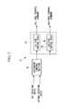
- Fig. 2 is a block diagram showing the electrical configuration of the ECU 12 of the first embodiment.
- the ECU 12 includes a governing control section 30 and a fuel control section 32.
- the governing control section 30 receives an input of a set rotating speed and an actual rotating speed of the dual-fuel diesel engine 1 and performs governing control such that the actual rotating speed becomes the set rotating speed, based on the difference between the set rotating speed and the actual rotating speed.
- the governing control section 30 may perform governing control based on the difference between a set load and an actual load.
- the load is identified by a load ratio (load indicator value) that varies within the range from 0 to 100, when the maximum load with respect to the dual-fuel diesel engine 1 is 100% load ratio.
- the fuel control section 32 outputs a fuel control command based on a command output from the governing control section 30.
- the fuel control section 32 of the first embodiment includes an oil-fuel control part 34 and a gas-fuel control part 36.
- the oil-fuel control part 34 calculates, based on a command output from the governing control section 30, an oil-fuel control command by using a predetermined function and outputs the oil-fuel control command to the oil-fuel injection valves 10.
- the gas-fuel control part 36 calculates, based on a command output from the governing control section 30, a gas-fuel control command by using a predetermined function and outputs the gas-fuel control command to the gas-fuel injection valves 8.
- Fig. 3 is a graph showing the relationship between the load ratio and the fuel control command.
- the fuel control command shown in Fig. 3 is the sum of the oil-fuel control command and the gas-fuel control command. Specifically, the total amount of supplied calorific value of gas fuel and oil fuel increases as the load ratio increases. As an example, the fuel control command increases in proportion to the load ratio.
- the fuel control section 32 starts supplying gas fuel after the load of the dual-fuel diesel engine 1 exceeds a predetermined value. Then, the fuel control section 32 controls the gas fuel and the oil fuel using different control amounts and increases the total amount of the supplied calorific value of the gas fuel and the oil fuel, according to increase in the load, as shown in Fig. 3 . Accordingly, the ECU 12 can reduce the use of the oil fuel in the dual-fuel diesel engine 1. Furthermore, because the ECU 12 controls the gas fuel and the oil fuel using different control amounts, another pattern of control of the gas fuel and the oil fuel can be performed according to the purpose.
- switching load ratio in the following description.
- the switching load ratio is set to 20% as an example, the value is not limited thereto and can be voluntarily set. Low-load operation is performed at a load ratio that is equal to or lower than the switching load ratio.
- the single-fuel combustion using oil fuel is switched to multi-fuel combustion using oil fuel and gas fuel.
- Fig. 4 is a graph showing a change in oil-fuel control command and a change in gas-fuel control command in the case where the load of the dual-fuel diesel engine 1 of the first embodiment increases.
- the rate of increase in the oil-fuel control command becomes smaller compared with that of the time when the load ratio is lower than the switching load ratio.
- the oil-fuel control command is the value obtained by subtracting the gas-fuel control command from the fuel control command shown in Fig. 3 . This decrease in the oil-fuel control command maintains the relationship between the fuel control command and the load ratio, as shown in Fig. 3 .
- the gas-fuel control command increases after a certain delay from the timing at which the load reaches the switching load ratio, and thereby supplying gas fuel is started after the certain delay.
- the fuel control section 32 reduces the rate of increase of the oil fuel supply compared with that before the load reaches the switching load ratio and starts supplying gas fuel after a certain delay from the timing at which the load reaches the switching load ratio.
- starting of the gas fuel supply after a certain delay from the timing at which the load reaches the switching load ratio means that supplying gas fuel is started when the load command becomes equal to or higher than a set value during a predetermined period of time (delay time ⁇ 1 in Fig. 5 ), for example.
- Reducing the rate of increase of the oil fuel supply means that the increase in the load becomes slower than before. Then, when the timing at which gas fuel is supplied is delayed, supplying gas fuel is started during the slow increase in the load. Therefore, a situation in which the load increases rapidly due to supplying gas fuel, with chattering, is prevented.
- the delay time ⁇ 1 for the timing at which the gas-fuel control command starts to increased is a period of time that the load ratio does not become equal to or lower than the switching load ratio at the timing even when load pullback (a decrease) occurs due to starting the gas fuel supply.
- the delay time ⁇ 1 is empirically obtained by operating the dual-fuel diesel engine 1 or is obtained from simulation, for example.
- the load (rotating speed) of the dual-fuel diesel engine 1 may decrease rapidly (dashed line in Fig. 6 ). In this case, chattering may occur, the load may exceed the switching load ratio again, and gas fuel supplying and stopping may be repeated, which may cause a situation in which frequent switching occurs between single-fuel combustion and multi-fuel combustion.
- the fuel control section 32 reduces the supply of oil fuel to the level less than that before the load reaches the switching load ratio, as shown in Fig. 4 , and supplying gas fuel is stopped after a certain delay from the timing at which the load reaches the switching load ratio, as shown in Fig. 7 .
- stopping the gas fuel supply after a certain delay from the timing at which the load reaches the switching load ratio means that supplying gas fuel is stopped when the load command becomes equal to or lower than a set value after a predetermined period of time (delay time ⁇ 2 in Fig. 6 ) passes, for example.
- the delay time ⁇ 2 for the timing at which outputting the gas-fuel control command is stopped is a period of time in which the load ratio does not exceed the switching load ratio even when load pullback (an increase) occurs due to stopping the gas fuel supply.
- the delay time ⁇ 2 is empirically obtained by operating the dual-fuel diesel engine 1 or is obtained from simulation, for example.
- the ECU 12 of the first embodiment has hysteresis in setting fuel supply starting (ON) and fuel supply stopping (OFF) of gas fuel.
- the ECU 12 provided in the dual-fuel diesel engine 1 of the first embodiment performs governor control in which, when the load increases to the switching load ratio, the ECU 12 reduces the rate of increase of the oil fuel supply compared with that before the load reaches to the switching load ratio and starts supplying gas fuel after a certain delay from the timing at which the load reaches the switching load ratio. Furthermore, when the load decreases to the switching load ratio, the ECU 12 reduces the oil fuel supply to the level less than that before the load reatches to the switching load ratio and stops supplying gas fuel after a certain delay from the timing at which the load reaches the switching load ratio.
- the ECU 12 can reduce the use of oil fuel and also allow stable operation using oil fuel and gas fuel.
- the ECU 12 of the second embodiment switches from the single-fuel combustion, which uses oil fuel, to the multi-fuel combustion, which uses oil fuel and gas fuel, when the load of the dual-fuel diesel engine 1 reaches a first switching load ratio. Furthermore, the ECU 12 switches from the multi-fuel combustion to the single-fuel combustion when the load of the dual-fuel diesel engine 1 reatches a second switching load ratio that is smaller than the first switching load ratio.
- Fig. 8 is a schematic view showing timings at which outputting a gas-fuel control command is started and stopped, according to the second embodiment.
- the ECU 12 provided in the dual-fuel diesel engine 1 of the second embodiment can reduce the use of oil fuel and also allow stable operation using oil fuel and gas fuel.
Landscapes
- Engineering & Computer Science (AREA)
- Chemical & Material Sciences (AREA)
- Combustion & Propulsion (AREA)
- Mechanical Engineering (AREA)
- General Engineering & Computer Science (AREA)
- Oil, Petroleum & Natural Gas (AREA)
- Output Control And Ontrol Of Special Type Engine (AREA)
- Electrical Control Of Air Or Fuel Supplied To Internal-Combustion Engine (AREA)
- Combustion Methods Of Internal-Combustion Engines (AREA)
Abstract
Description
- The present invention relates to a diesel engine control device, a diesel engine, and a diesel engine control method.
- There are known diesel engines (hereinafter, referred to as "dual-fuel diesel engines") in which gas fuel, such as natural gas, is used as main fuel, oil fuel having excellent compression ignition capability is used as pilot fuel, and self-ignition of the oil fuel is caused in a high-temperature combustion chamber, thereby combusting the gas fuel as main fuel. Because the dual-fuel diesel engines use gas fuel, emissions of CO2 and hazardous substances, such as black smoke, are less during the combustion.
- For example, PTL 1 discloses a dual-fuel diesel engine in which low-cetane fuel having poor compression ignition capability, such as gas fuel, is used as main fuel, and oil fuel having excellent compression ignition capability is used as pilot fuel. The engine disclosed in PTL 1 has gas-fuel injection valves and pilot-fuel injection valves that are provided in a cylinder head, gas fuel and pilot fuel are injected from the gas-fuel injection valves and the pilot-fuel injection valves toward a combustion chamber, and self-ignition of the pilot fuel is caused in the high-temperature combustion chamber, thereby combusting the main fuel.
- {PTL 1} Japanese Unexamined Utility Model Application, Publication No.
S62-45339 - However, PTL 1 does not disclose a specific method for supplying oil fuel and gas fuel to the diesel engine. In dual-fuel diesel engines, stable operation using oil fuel and gas fuel is to be achieved.
- The present invention is made in view of such circumstances, and an object thereof is to provide a diesel engine control device, a diesel engine, and a diesel engine control method that are capable of reducing the use of oil fuel and also allowing stable operation using oil fuel and gas fuel.
- In order to solve the above-described problem, a diesel engine control device, a diesel engine, and a diesel engine control method of the present invention employ the following solutions.
- A first aspect of the present invention provides a diesel engine control device for a diesel engine that is operated by being supplied with gas fuel and oil fuel, the control device comprising: a governor control unit for performing governor control; and a fuel control unit for reducing a rate of increase of oil fuel supply compared with that before a load of the diesel engine reaches a predetermined value, and for starting gas fuel supply after a certain delay from timing at which the load reaches the predetermined value.
- According to this configuration, the diesel engine control device controls the gas fuel supply and the oil fuel supply to the diesel engine. Supplying gas fuel and oil fuel is conducted through governor control by the governor control means. Then, when the load of the diesel engine increases to the predetermined value, the single-fuel combustion, which uses oil fuel, is switched to the multi-fuel combustion, which uses oil fuel and gas fuel.
- However, if supplying gas fuel is started at the same time when the load of the diesel engine increases and reaches the predetermined value, the load (rotating speed) of the diesel engine may increase rapidly. In such a case, in order to reduce the rapidly increased load, the supply of fuel is reduced through governor control. However, as a result, the load decreases too much, and control is performed so as to increase the load again, so that so-called chattering may occur. Then, when the load decreases too much and becomes equal to or lower than the predetermined value again, supplying gas fuel is stopped. In this way, when chattering occurs, gas fuel supplying and stopping are repeated, which may cause a situation in which frequent switching occurs between single-fuel combustion and multi-fuel combustion.
- Therefore, according to this configuration, when the load of the diesel engine increases to the predetermined value, the rate of increase of the oil fuel supply is reduced compared with that before the load reaches the predetermined value, and supplying gas fuel is started after a certain delay from the timing at which the load reaches the predetermined value.
- Reducing the rate of increase of the oil fuel supply means that the increase in the load becomes slower than before. Then, when the timing at which gas fuel is supplied is delayed, supplying gas fuel is started during the slow increase in the load. Therefore, a situation in which the load increases rapidly due to supplying gas fuel, with chattering, is prevented.
- Therefore, with this configuration, it is possible to reduce the use of oil fuel and also to allow stable operation using oil fuel and gas fuel.
- In the above-described first aspect, it is preferable that the fuel control unit reduces the supply of the oil fuel compared with that before the load decreases and reaches the predetermined value and stops supplying the gas fuel after a certain delay from timing at which the load reaches the predetermined value.
- When the supply of oil fuel is reduced, if supplying gas fuel is stopped at the same time when the load of the diesel engine decreases and reaches the predetermined value, the load (rotating speed) of the diesel engine may decrease rapidly. In this case, chattering may occur, and, when the load exceeds the predetermined value again, gas fuel supplying and stopping are repeated, which may cause a situation in which frequent switching occurs between single-fuel combustion and multi-fuel combustion.
- Therefore, according to this configuration, when the load decreases to the predetermined value, the supply of oil fuel is reduced, and supplying gas fuel is stopped after a certain delay from the timing at which the load reaches the predetermined value.
- As a result, because a reduction in the supply of oil fuel and stopping of the gas fuel supply do not occur at the same time, a situation in which the load decreases rapidly, with chattering, is prevented with this configuration.
- A second aspect of the present invention provides a diesel engine control device for a diesel engine that is operated by being supplied with gas fuel and oil fuel, the control device comprising: a governor control unit for performing governor control; and a fuel control unit for switching from single-fuel combustion using the oil fuel to multi-fuel combustion using the oil fuel and the gas fuel when a load of the diesel engine increases and reaches a first predetermined value, and for switching from the multi-fuel combustion to the single-fuel combustion when the load of the diesel engine decreases and reaches a second predetermined value smaller than the first value.
- According to this configuration, when the load of the diesel engine increases and reaches the first predetermined value, the single-fuel combustion, which uses oil fuel, is switched to the multi-fuel combustion, which uses oil fuel and gas fuel. Then, when the load of the diesel engine decreases and reaches the second predetermined value, which is smaller than the first load, the multi-fuel combustion is switched to the single-fuel combustion. As a result, when the single-fuel combustion is switched to the multi-fuel combustion, even if chattering occurs and thus the load decreases, it is possible to prevent switching to the single-fuel combustion again. Furthermore, when the multi-fuel combustion is switched to the single-fuel combustion, even if chattering occurs and thus the load increases, it is possible to prevent switching to the multi-fuel combustion again.
- Therefore, with this configuration, it is possible to reduce the use of oil fuel and also to allow stable operation using oil fuel and gas fuel.
- A third aspect of the present invention provides a diesel engine including: a gas-fuel injection valve that is provided in a combustion chamber and that injects gas fuel; an oil-fuel injection valve that is provided in the combustion chamber and that injects oil fuel; and the above-described control device.
- A fourth aspect of the present invention provides a diesel engine control method for a diesel engine that is operated by being supplied with gas fuel and oil fuel, the control method comprising: a first step of reducing the rate of increase of oil fuel supply compared with that before a load of the diesel engine increases and reaches a predetermined value; and a second step of starting gas fuel supply after a certain delay from timing at which the load decreases and reaches the predetermined value.
- A fifth aspect of the present invention provides a diesel engine control method for a diesel engine that is operated by being supplied with gas fuel and oil fuel, the control method comprising: a first step of switching from single-fuel combustion using the oil fuel to multi-fuel combustion using the oil fuel and the gas fuel when a load of the diesel engine increases and reaches a first predetermined value; and a second step of switching from the multi-fuel combustion to the single-fuel combustion when the load of the diesel engine decreases and reaches a second predetermined value smaller than the first value.
- According to the present invention, an advantageous effect of making it possible to reduce the use of oil fuel and also to allow stable operation using oil fuel and gas fuel.
-
- {
Fig. 1} Fig. 1 is a view showing the configuration of a dual-fuel diesel engine according to a first embodiment of the present invention. - {
Fig. 2} Fig. 2 is a block diagram showing the electrical configuration of an ECU according to the first embodiment of the present invention. - {
Fig. 3} Fig. 3 is a graph showing a relationship between the sum of fuel control commands for oil fuel and gas fuel, and the load ratio, according to the first embodiment of the present invention. - {
Fig. 4} Fig. 4 is a graph showing a change in oil-fuel control command and a change in gas-fuel control command in the case where the load of the dual-fuel diesel engine according to the first embodiment of the present invention increases. - {
Fig. 5} Fig. 5 is a time chart in the case where the load of the dual-fuel diesel engine according to the first embodiment of the present invention increases. - {
Fig. 6} Fig. 6 is a time chart in the case where the load of the dual-fuel diesel engine according to the first embodiment of the present invention decreases. - {
Fig. 7} Fig. 7 is a graph showing a change in gas-fuel control command in the case where the load of the dual-fuel diesel engine according to the first embodiment of the present invention decreases. - {
Fig. 8} Fig. 8 is a schematic view showing timing at which output of a gas-fuel control command is started and stopped, according to a second embodiment of the present invention. - A diesel engine control device, a diesel engine, and a diesel engine control method according to one embodiment of the present invention will be described below with reference to the drawings.
- A first embodiment of the present invention will be described below.
- A diesel engine according to the first embodiment is a dual-fuel diesel engine that is operated by using gas fuel as main fuel and by using oil fuel as pilot fuel, and is used as a main engine of a ship, for example.
-
Fig. 1 is a view showing the configuration of a dual-fuel diesel engine 1 of the first embodiment. - The dual-fuel diesel engine 1 includes a
cylindrical cylinder 2, acylinder head 3 that is fixed on an upper end of thecylinder 2, and apiston 4 that is movably accommodated in thecylinder 2 so as to move forward and backward. A combustion chamber c is formed by acircumferential wall 2a of thecylinder 2, thecylinder head 3, and atop surface 4a of thepiston 4. - Note that
reference sign 5 in the figure denotes a piston ring. -
Scavenge ports 6 are open in thecircumferential wall 2a at lower portions of thecylinder 2. Thescavenge ports 6 are formed at positions higher than thetop surface 4a (indicated by the two-dot chain line in the figure) of thepiston 4 located in the vicinity of a bottom dead position, so that air is supplied from thescavenge ports 6 to the combustion chamber c when thepiston 4 is located in the vicinity of the bottom dead position. Furthermore, at the top of thecylinder head 3, an exhaust port is open, and an exhaust valve 7 that opens and closes the exhaust port is provided. The exhaust valve 7 is open until thepiston 4 reaches a position which is about 100 degrees before the top dead position, during a scavenging process in which thepiston 4 is moving upward. Then, exhaust gas remaining in the combustion chamber c from the prior process is scavenged by air supplied from thescavenge ports 6 to the combustion chamber c. - The
cylinder head 3 is provided with gas-fuel injection valves 8 that inject gas fuel into the combustion chamber c and oil-fuel injection valves 10 that similarly inject oil fuel, which has excellent compression ignition capability, into the combustion chamber c. The gas-fuel injection valves 8 are provided at positions that are 180-degree away from each other in the circumferential direction with reference to a cylinder center o serving as the rotation center. The oil-fuel injection valves 10 are provided at positions that are 180-degree away from each other in the circumferential direction with reference to the cylinder center o serving as the rotation center. - Note that, in the first embodiment, although four injection holes are provided in each of the gas-
fuel injection valves 8 and also in each of the oil-fuel injection valves 10, the number of the gas-fuel injection valves 8 and the number of the oil-fuel injection valves 10 are not limited and, for example, may be one. However, in the first embodiment, in which the exhaust valve 7 is provided at the top of thecylinder head 3, it is preferable that a plurality of gas-fuel injection valves 8 and a plurality of oil-fuel injection valves 10 be respectively arranged at equal intervals in the circumferential direction. - Furthermore, the gas-
fuel injection valves 8 and the oil-fuel injection valves 10 are connected to an engine control unit (hereinafter, referred to as "ECU") 12 viacables 14. - The
ECU 12 is connected, via acable 16, to acrank angle sensor 15 that detects the angle of rotation of acrankshaft 17. Then, a signal indicating the angle of rotation of thecrankshaft 17 is received from thecrank angle sensor 15, thereby the phase of thepiston 4 is detected. Furthermore, the gas-fuel injection valves 8 and the oil-fuel injection valves 10 inject gas fuel and oil fuel into the combustion chamber c at predetermined timings based on signals sent from theECU 12. -
Fig. 2 is a block diagram showing the electrical configuration of theECU 12 of the first embodiment. - The
ECU 12 includes a governingcontrol section 30 and afuel control section 32. - The governing
control section 30 receives an input of a set rotating speed and an actual rotating speed of the dual-fuel diesel engine 1 and performs governing control such that the actual rotating speed becomes the set rotating speed, based on the difference between the set rotating speed and the actual rotating speed. Note that the governingcontrol section 30 may perform governing control based on the difference between a set load and an actual load. Note that, in the first embodiment, the load is identified by a load ratio (load indicator value) that varies within the range from 0 to 100, when the maximum load with respect to the dual-fuel diesel engine 1 is 100% load ratio. - The
fuel control section 32 outputs a fuel control command based on a command output from the governingcontrol section 30. - The
fuel control section 32 of the first embodiment includes an oil-fuel control part 34 and a gas-fuel control part 36. - The oil-
fuel control part 34 calculates, based on a command output from the governingcontrol section 30, an oil-fuel control command by using a predetermined function and outputs the oil-fuel control command to the oil-fuel injection valves 10. - The gas-
fuel control part 36 calculates, based on a command output from the governingcontrol section 30, a gas-fuel control command by using a predetermined function and outputs the gas-fuel control command to the gas-fuel injection valves 8. -
Fig. 3 is a graph showing the relationship between the load ratio and the fuel control command. - The fuel control command shown in
Fig. 3 is the sum of the oil-fuel control command and the gas-fuel control command. Specifically, the total amount of supplied calorific value of gas fuel and oil fuel increases as the load ratio increases. As an example, the fuel control command increases in proportion to the load ratio. - The
fuel control section 32 starts supplying gas fuel after the load of the dual-fuel diesel engine 1 exceeds a predetermined value. Then, thefuel control section 32 controls the gas fuel and the oil fuel using different control amounts and increases the total amount of the supplied calorific value of the gas fuel and the oil fuel, according to increase in the load, as shown inFig. 3 . Accordingly, theECU 12 can reduce the use of the oil fuel in the dual-fuel diesel engine 1. Furthermore, because theECU 12 controls the gas fuel and the oil fuel using different control amounts, another pattern of control of the gas fuel and the oil fuel can be performed according to the purpose. - Note that the above-described predetermined value is referred to as switching load ratio in the following description. In the first embodiment, although the switching load ratio is set to 20% as an example, the value is not limited thereto and can be voluntarily set. Low-load operation is performed at a load ratio that is equal to or lower than the switching load ratio.
- Specifically, when the load ratio of the dual-fuel diesel engine 1 increases and exceeds the switching load ratio, the single-fuel combustion using oil fuel is switched to multi-fuel combustion using oil fuel and gas fuel.
- On the other hand, when the load ratio of the dual-fuel diesel engine 1 that is equal to or higher than the switching load ratio decreases and becomes equal to or lower than the switching load ratio, supplying gas fuel is stopped, and the multi-fuel combustion is switched to the single-fuel combustion.
-
Fig. 4 is a graph showing a change in oil-fuel control command and a change in gas-fuel control command in the case where the load of the dual-fuel diesel engine 1 of the first embodiment increases. - As shown in
Fig. 4 , when the load ratio exceeds the switching load ratio, the rate of increase in the oil-fuel control command becomes smaller compared with that of the time when the load ratio is lower than the switching load ratio. In other words, the oil-fuel control command is the value obtained by subtracting the gas-fuel control command from the fuel control command shown inFig. 3 . This decrease in the oil-fuel control command maintains the relationship between the fuel control command and the load ratio, as shown inFig. 3 . - On the other hand, the gas-fuel control command increases after a certain delay from the timing at which the load reaches the switching load ratio, and thereby supplying gas fuel is started after the certain delay.
- This is because, if supplying gas fuel is started at the same time when the load of the dual-fuel diesel engine 1 increases and reaches the switching load ratio, the load (rotating speed) of the dual-fuel diesel engine 1 may increase rapidly. In such a case, in order to reduce the increased load, the supply of fuel is reduced through governor control. However, as a result, so-called chattering in which the load decreases too much and is increased again, as shown in
Fig. 5 , may occur. Note that the solid line inFig. 5 indicates a case in which the load ratio increases as time passes without the occurrence of chattering even when the combustion mode is switched to the multi-fuel combustion. On the other hand, the dashed line inFig. 5 indicates a case in which chattering occurs when the combustion mode is switched to the multi-fuel combustion. - Then, when load pullback occurs, in which the load decreases too much and becomes equal to or lower than the switching load ratio again, supplying gas fuel is stopped. When chattering occurs by the pullback, gas fuel supplying and stopping are repeated, which may cause a situation in which frequent switching occurs between single-fuel combustion and multi-fuel combustion.
- Accordingly, as described above, when the load of the dual-fuel diesel engine 1 increases to the switching load ratio, the
fuel control section 32 reduces the rate of increase of the oil fuel supply compared with that before the load reaches the switching load ratio and starts supplying gas fuel after a certain delay from the timing at which the load reaches the switching load ratio. Note that starting of the gas fuel supply after a certain delay from the timing at which the load reaches the switching load ratio means that supplying gas fuel is started when the load command becomes equal to or higher than a set value during a predetermined period of time (delay time ε1 inFig. 5 ), for example. - Reducing the rate of increase of the oil fuel supply means that the increase in the load becomes slower than before. Then, when the timing at which gas fuel is supplied is delayed, supplying gas fuel is started during the slow increase in the load. Therefore, a situation in which the load increases rapidly due to supplying gas fuel, with chattering, is prevented.
- Note that the delay time ε1 for the timing at which the gas-fuel control command starts to increased is a period of time that the load ratio does not become equal to or lower than the switching load ratio at the timing even when load pullback (a decrease) occurs due to starting the gas fuel supply. The delay time ε1 is empirically obtained by operating the dual-fuel diesel engine 1 or is obtained from simulation, for example.
- Furthermore, when the load of the dual-fuel diesel engine 1 decreases and reaches the switching load ratio (20%), the supply of oil fuel is reduced to less than that before the load reaches the switching load ratio, as shown in
Fig. 4 . In other words, the rate of decrease of the oil fuel supply becomes larger. - Thus, when the supply of oil fuel is reduced, if supplying gas fuel is stopped at the same time when the load of the dual-fuel diesel engine 1 decreases and reaches the switching load ratio, the load (rotating speed) of the dual-fuel diesel engine 1 may decrease rapidly (dashed line in
Fig. 6 ). In this case, chattering may occur, the load may exceed the switching load ratio again, and gas fuel supplying and stopping may be repeated, which may cause a situation in which frequent switching occurs between single-fuel combustion and multi-fuel combustion. - Accordingly, when the load decreases to the switching load ratio, the
fuel control section 32 reduces the supply of oil fuel to the level less than that before the load reaches the switching load ratio, as shown inFig. 4 , and supplying gas fuel is stopped after a certain delay from the timing at which the load reaches the switching load ratio, as shown inFig. 7 . Note that stopping the gas fuel supply after a certain delay from the timing at which the load reaches the switching load ratio means that supplying gas fuel is stopped when the load command becomes equal to or lower than a set value after a predetermined period of time (delay time ε2 inFig. 6 ) passes, for example. - As a result, because a reduction in the supply of oil fuel and stopping the gas fuel supply do not occur at the same time, a situation in which the load decreases rapidly, with chattering, is prevented.
- Note that the delay time ε2 for the timing at which outputting the gas-fuel control command is stopped is a period of time in which the load ratio does not exceed the switching load ratio even when load pullback (an increase) occurs due to stopping the gas fuel supply. The delay time ε2 is empirically obtained by operating the dual-fuel diesel engine 1 or is obtained from simulation, for example.
- In this way, the
ECU 12 of the first embodiment has hysteresis in setting fuel supply starting (ON) and fuel supply stopping (OFF) of gas fuel. - As described above, the
ECU 12 provided in the dual-fuel diesel engine 1 of the first embodiment performs governor control in which, when the load increases to the switching load ratio, theECU 12 reduces the rate of increase of the oil fuel supply compared with that before the load reaches to the switching load ratio and starts supplying gas fuel after a certain delay from the timing at which the load reaches the switching load ratio. Furthermore, when the load decreases to the switching load ratio, theECU 12 reduces the oil fuel supply to the level less than that before the load reatches to the switching load ratio and stops supplying gas fuel after a certain delay from the timing at which the load reaches the switching load ratio. - As a result, the
ECU 12 can reduce the use of oil fuel and also allow stable operation using oil fuel and gas fuel. - A second embodiment of the present invention will be described below.
- Because the configurations of a dual-fuel diesel engine 1 and an
ECU 12 of the second embodiment are the same as those of the dual-fuel diesel engine 1 and theECU 12 of the first embodiment, which are shown inFigs. 1 and2 , a description thereof will be omitted. - Note that the
ECU 12 of the second embodiment switches from the single-fuel combustion, which uses oil fuel, to the multi-fuel combustion, which uses oil fuel and gas fuel, when the load of the dual-fuel diesel engine 1 reaches a first switching load ratio. Furthermore, theECU 12 switches from the multi-fuel combustion to the single-fuel combustion when the load of the dual-fuel diesel engine 1 reatches a second switching load ratio that is smaller than the first switching load ratio. -
Fig. 8 is a schematic view showing timings at which outputting a gas-fuel control command is started and stopped, according to the second embodiment. - As shown in
Fig. 8 , when the load of the dual-fuel diesel engine 1 reaches a first switching load ratio L1, the gas-fuel control part 36 starts outputting a gas-fuel control command. On the other hand, when the load of the dual-fuel diesel engine 1 reaches a second switching load ratio L2, the gas-fuel control part 36 stops outputting the gas-fuel control command. - As a result, when the single-fuel combustion is switched to the multi-fuel combustion, even if chattering occurs and thus the load decreases, it is possible to prevent switching to the single-fuel combustion again. Furthermore, when the multi-fuel combustion is switched to the single-fuel combustion, even if chattering occurs and thus the load increases, it is possible to prevent switching to the multi-fuel combustion again.
- Therefore, the
ECU 12 provided in the dual-fuel diesel engine 1 of the second embodiment can reduce the use of oil fuel and also allow stable operation using oil fuel and gas fuel. - Although the present invention has been described above by using the embodiments, the technical scope of the present invention is not limited to the scope of the above-described embodiments. Various changes or improvements can be added to the above-described embodiments without departing from the scope of the invention, and an embodiment to which such changes or improvements are added is also encompassed in the technical scope of the present invention.
-
- 1
- dual-fuel diesel engine
- 12
- ECU
- 30
- governing control section
- 32
- fuel control section
Claims (6)
- A diesel engine control device for a diesel engine that is operated by being supplied with gas fuel and oil fuel, the control device comprising:a governor control unit for performing governor control; anda fuel control unit for reducing a rate of increase of oil fuel supply compared with that before a load of the diesel engine reaches a predetermined value, and for starting gas fuel supply after a certain delay from timing at which the load reaches the predetermined value.
- The diesel engine control device according to claim 1, wherein, the fuel control unit reduces the supply of the oil fuel compared with that before the load decreases and reaches the predetermined value and stops supplying the gas fuel after a certain delay from timing at which the load reaches the predetermined value.
- A diesel engine control device for a diesel engine that is operated by being supplied with gas fuel and oil fuel, the control device comprising:a governor control unit for performing governor control; anda fuel control unit for switching from single-fuel combustion using the oil fuel to multi-fuel combustion using the oil fuel and the gas fuel when a load of the diesel engine increases and reaches a first predetermined value, and for switching from the multi-fuel combustion to the single-fuel combustion when the load of the diesel engine decreases and reaches a second predetermined value smaller than the first value.
- A diesel engine comprising:a gas-fuel injection valve that is provided in a combustion chamber and that injects gas fuel;an oil-fuel injection valve that is provided in the combustion chamber and that injects oil fuel; anda control device according to any one of claims 1 to 3.
- A diesel engine control method for a diesel engine that is operated by being supplied with gas fuel and oil fuel, the control method comprising:a first step of reducing the rate of increase of oil fuel supply compared with that before a load of the diesel engine increases and reaches a predetermined value; anda second step of starting gas fuel supply after a certain delay from timing at which the load decreases and reaches the predetermined value.
- A diesel engine control method for a diesel engine that is operated by being supplied with gas fuel and oil fuel, the control method comprising:a first step of switching from single-fuel combustion using the oil fuel to multi-fuel combustion using the oil fuel and the gas fuel when a load of the diesel engine increases and reaches a first predetermined value; anda second step of switching from the multi-fuel combustion to the single-fuel combustion when the load of the diesel engine decreases and reaches a second predetermined value smaller than the first value.
Applications Claiming Priority (2)
| Application Number | Priority Date | Filing Date | Title |
|---|---|---|---|
| JP2012250229A JP6049415B2 (en) | 2012-11-14 | 2012-11-14 | Diesel engine control device, diesel engine, and diesel engine control method |
| PCT/JP2013/067409 WO2014076995A1 (en) | 2012-11-14 | 2013-06-25 | Diesel engine control device, diesel engine, and diesel engine control method |
Publications (4)
| Publication Number | Publication Date |
|---|---|
| EP2921675A1 true EP2921675A1 (en) | 2015-09-23 |
| EP2921675A4 EP2921675A4 (en) | 2016-06-01 |
| EP2921675B1 EP2921675B1 (en) | 2017-10-18 |
| EP2921675B8 EP2921675B8 (en) | 2017-11-29 |
Family
ID=50730921
Family Applications (1)
| Application Number | Title | Priority Date | Filing Date |
|---|---|---|---|
| EP13855962.0A Not-in-force EP2921675B8 (en) | 2012-11-14 | 2013-06-25 | Diesel engine control device, diesel engine, and diesel engine control method |
Country Status (5)
| Country | Link |
|---|---|
| EP (1) | EP2921675B8 (en) |
| JP (1) | JP6049415B2 (en) |
| KR (1) | KR20150056646A (en) |
| CN (1) | CN104769260B (en) |
| WO (1) | WO2014076995A1 (en) |
Cited By (4)
| Publication number | Priority date | Publication date | Assignee | Title |
|---|---|---|---|---|
| WO2016154086A1 (en) * | 2015-03-26 | 2016-09-29 | Cummins Inc. | Dual fuel engine and method for cylinder bank cutout during light load conditions |
| EP3170734A4 (en) * | 2014-07-18 | 2018-08-01 | Daewoo Shipbuilding & Marine Engineering Co., Ltd. | Method for operating engine for vessel |
| WO2018166613A1 (en) * | 2017-03-17 | 2018-09-20 | Wärtsilä Finland Oy | Method of controlling a multi-fuel internal combustion piston engine and a fuel injection control system for a multi-fuel internal combustion piston engine |
| WO2023186972A1 (en) * | 2022-03-30 | 2023-10-05 | Man Truck & Bus Se | Control device for a dual-fuel internal combustion engine |
Families Citing this family (6)
| Publication number | Priority date | Publication date | Assignee | Title |
|---|---|---|---|---|
| JP6049415B2 (en) * | 2012-11-14 | 2016-12-21 | 三菱重工業株式会社 | Diesel engine control device, diesel engine, and diesel engine control method |
| CN104791075A (en) * | 2015-04-20 | 2015-07-22 | 吉林大学 | Ignition-mode-variable diesel/natural gas dual-fuel engine and control method thereof |
| KR102066631B1 (en) * | 2015-08-12 | 2020-01-15 | 대우조선해양 주식회사 | Engine system of vessel |
| WO2019049362A1 (en) * | 2017-09-11 | 2019-03-14 | 新潟原動機株式会社 | Engine operation method and engine system |
| JP2022146665A (en) | 2021-03-22 | 2022-10-05 | ヤンマーホールディングス株式会社 | engine |
| JP7788926B2 (en) * | 2022-04-19 | 2025-12-19 | 株式会社ジャパンエンジンコーポレーション | Marine engines |
Family Cites Families (22)
| Publication number | Priority date | Publication date | Assignee | Title |
|---|---|---|---|---|
| GB1370619A (en) * | 1971-12-15 | 1974-10-30 | Exxon Research Engineering Co | Operation of compression-ignition engines |
| JPS5718446A (en) * | 1980-07-09 | 1982-01-30 | Hitachi Ltd | Fuel feed device for internal combustion engine |
| JPS6245339U (en) | 1985-09-10 | 1987-03-19 | ||
| JPS6296742A (en) * | 1985-10-22 | 1987-05-06 | Mazda Motor Corp | Idling speed controller for engine |
| JPH0643814B2 (en) * | 1986-03-14 | 1994-06-08 | トヨタ自動車株式会社 | Dual fuel switching control method and device |
| JPS6390633A (en) * | 1986-10-03 | 1988-04-21 | Toyota Motor Corp | Transfer controlling method for binary fuel and device thereof |
| JPH02153238A (en) * | 1988-12-02 | 1990-06-12 | Mitsui Eng & Shipbuild Co Ltd | Control device for duplex fuel diesel engine |
| JPH08158980A (en) * | 1994-12-06 | 1996-06-18 | Mitsubishi Motors Corp | Auxiliary fuel ignition type gas engine and its operating method |
| DK174242B1 (en) * | 1996-01-15 | 2002-10-14 | Man B & W Diesel As | A method of controlling the fuel supply to a diesel engine capable of supplying fuel oil and fuel gas with high pressure injection boats, and a high pressure gas injection engine of the diesel type. |
| DE19719760A1 (en) * | 1997-05-10 | 1998-11-12 | Bosch Gmbh Robert | System for operating a direct-injection internal combustion engine, in particular a motor vehicle |
| JPH11324750A (en) * | 1998-05-13 | 1999-11-26 | Niigata Eng Co Ltd | Combined engine and its operating method |
| CA2398149A1 (en) * | 2000-02-11 | 2001-08-16 | Patric Ouellette | Method and apparatus for dual fuel injection into an internal combustion engine |
| GB2375796A (en) * | 2001-04-24 | 2002-11-27 | William May Stott | Supplying turbo-diesel i.c. engines with supplementary fuel |
| JP2003184591A (en) * | 2001-12-21 | 2003-07-03 | Aisan Ind Co Ltd | Fuel supply method and device for internal combustion engine |
| GB0205062D0 (en) * | 2002-03-05 | 2002-04-17 | Autogas Supplies Ltd | Dual fuel engine |
| JP2004108153A (en) * | 2002-09-13 | 2004-04-08 | Tokyo Gas Co Ltd | Dual fuel engine |
| JP4158907B2 (en) * | 2003-08-21 | 2008-10-01 | ヤンマー株式会社 | Control method of dual fuel engine |
| JP4747687B2 (en) * | 2005-06-07 | 2011-08-17 | トヨタ自動車株式会社 | Control device for bi-fuel engine |
| US7621257B1 (en) * | 2008-05-01 | 2009-11-24 | Ford Global Technologies, Llc | Engine valve operation |
| WO2011153069A1 (en) * | 2010-06-01 | 2011-12-08 | Cummins Intellectual Properties, Inc. | Control system for dual fuel engines |
| CN102588126B (en) * | 2011-12-16 | 2014-11-05 | 江苏蓝色船舶动力有限公司 | Diesel-LNG (liquefied natural gas) dual-fuel engine management system for inland navigation vessel |
| JP6049415B2 (en) * | 2012-11-14 | 2016-12-21 | 三菱重工業株式会社 | Diesel engine control device, diesel engine, and diesel engine control method |
-
2012
- 2012-11-14 JP JP2012250229A patent/JP6049415B2/en active Active
-
2013
- 2013-06-25 EP EP13855962.0A patent/EP2921675B8/en not_active Not-in-force
- 2013-06-25 KR KR1020157010103A patent/KR20150056646A/en not_active Ceased
- 2013-06-25 CN CN201380054543.5A patent/CN104769260B/en active Active
- 2013-06-25 WO PCT/JP2013/067409 patent/WO2014076995A1/en not_active Ceased
Cited By (5)
| Publication number | Priority date | Publication date | Assignee | Title |
|---|---|---|---|---|
| EP3170734A4 (en) * | 2014-07-18 | 2018-08-01 | Daewoo Shipbuilding & Marine Engineering Co., Ltd. | Method for operating engine for vessel |
| WO2016154086A1 (en) * | 2015-03-26 | 2016-09-29 | Cummins Inc. | Dual fuel engine and method for cylinder bank cutout during light load conditions |
| US10100723B2 (en) | 2015-03-26 | 2018-10-16 | Cummins Inc. | Dual fuel architecture and method for cylinder bank cutout and increased gas substitution during light load conditions |
| WO2018166613A1 (en) * | 2017-03-17 | 2018-09-20 | Wärtsilä Finland Oy | Method of controlling a multi-fuel internal combustion piston engine and a fuel injection control system for a multi-fuel internal combustion piston engine |
| WO2023186972A1 (en) * | 2022-03-30 | 2023-10-05 | Man Truck & Bus Se | Control device for a dual-fuel internal combustion engine |
Also Published As
| Publication number | Publication date |
|---|---|
| WO2014076995A1 (en) | 2014-05-22 |
| CN104769260A (en) | 2015-07-08 |
| EP2921675B1 (en) | 2017-10-18 |
| EP2921675A4 (en) | 2016-06-01 |
| JP2014098338A (en) | 2014-05-29 |
| EP2921675B8 (en) | 2017-11-29 |
| KR20150056646A (en) | 2015-05-26 |
| JP6049415B2 (en) | 2016-12-21 |
| CN104769260B (en) | 2017-09-01 |
Similar Documents
| Publication | Publication Date | Title |
|---|---|---|
| EP2921675B1 (en) | Diesel engine control device, diesel engine, and diesel engine control method | |
| CN104126066B (en) | Double-fuel diesel engine | |
| JP5851918B2 (en) | Dual fuel diesel engine and operating method thereof | |
| EP2957753B1 (en) | Fuel control device for gas engine | |
| CN106168175B (en) | Large diesel engine, method for operating a large diesel engine, and use of a method | |
| CN103502609A (en) | Method of operating an internal combustion piston engine in transient load change, a control system for controlling the operating of an internal combustion engine, and a piston engine | |
| KR102624243B1 (en) | A low-load operation method for operating a reciprocating piston internal combustion engine, computer program product, as well as a reciprocating piston internal combustion engine | |
| WO2014077002A1 (en) | Diesel engine control device, diesel engine, and diesel engine control method | |
| CN109983212B (en) | Engine response to derate by skip spark/fuel strategy | |
| CN111636969A (en) | Oil supply and air supply control method and system for two-stroke dual-fuel engine | |
| US8812217B2 (en) | Fuel injection controller and internal combustion engine | |
| US9534555B2 (en) | Control device and method for internal combustion engine | |
| JP2022180359A (en) | Lube oil controlled ignition engine combustion | |
| JP6432635B2 (en) | Control device for compression self-ignition engine | |
| KR101361409B1 (en) | Transient operation section control method for gasoline/diesel duel fuel powered combustion engine system | |
| EP3140535B1 (en) | Method in controlling a dual fuel engine | |
| JP2010216326A (en) | Method for controlling switching of combustion method of internal combustion engine | |
| WO2012114482A1 (en) | Internal combustion engine control system | |
| CN107743544B (en) | Dual-fuel internal combustion engine | |
| JP2010127087A (en) | Combustion control device of internal combustion engine | |
| CN110067684B (en) | Control method for combustion stability of dual-fuel engine under high-load working condition | |
| CN103204154A (en) | Coordination of fuel cutoff for fault detection and hybrid operation | |
| JP2010127088A (en) | Combustion control device of internal combustion engine |
Legal Events
| Date | Code | Title | Description |
|---|---|---|---|
| PUAI | Public reference made under article 153(3) epc to a published international application that has entered the european phase |
Free format text: ORIGINAL CODE: 0009012 |
|
| 17P | Request for examination filed |
Effective date: 20150420 |
|
| AK | Designated contracting states |
Kind code of ref document: A1 Designated state(s): AL AT BE BG CH CY CZ DE DK EE ES FI FR GB GR HR HU IE IS IT LI LT LU LV MC MK MT NL NO PL PT RO RS SE SI SK SM TR |
|
| AX | Request for extension of the european patent |
Extension state: BA ME |
|
| DAX | Request for extension of the european patent (deleted) | ||
| REG | Reference to a national code |
Ref country code: DE Ref legal event code: R079 Ref document number: 602013028240 Country of ref document: DE Free format text: PREVIOUS MAIN CLASS: F02D0019080000 Ipc: F02B0003060000 |
|
| RA4 | Supplementary search report drawn up and despatched (corrected) |
Effective date: 20160429 |
|
| RIC1 | Information provided on ipc code assigned before grant |
Ipc: F02D 41/02 20060101ALI20160422BHEP Ipc: F02D 19/10 20060101ALI20160422BHEP Ipc: F02D 19/06 20060101ALI20160422BHEP Ipc: F02D 41/30 20060101ALI20160422BHEP Ipc: F02D 41/00 20060101ALI20160422BHEP Ipc: F02B 3/06 20060101AFI20160422BHEP Ipc: F02D 19/08 20060101ALI20160422BHEP Ipc: F02D 31/00 20060101ALI20160422BHEP Ipc: F02B 23/02 20060101ALI20160422BHEP |
|
| GRAP | Despatch of communication of intention to grant a patent |
Free format text: ORIGINAL CODE: EPIDOSNIGR1 |
|
| STAA | Information on the status of an ep patent application or granted ep patent |
Free format text: STATUS: GRANT OF PATENT IS INTENDED |
|
| INTG | Intention to grant announced |
Effective date: 20170425 |
|
| GRAS | Grant fee paid |
Free format text: ORIGINAL CODE: EPIDOSNIGR3 |
|
| GRAA | (expected) grant |
Free format text: ORIGINAL CODE: 0009210 |
|
| STAA | Information on the status of an ep patent application or granted ep patent |
Free format text: STATUS: THE PATENT HAS BEEN GRANTED |
|
| AK | Designated contracting states |
Kind code of ref document: B1 Designated state(s): AL AT BE BG CH CY CZ DE DK EE ES FI FR GB GR HR HU IE IS IT LI LT LU LV MC MK MT NL NO PL PT RO RS SE SI SK SM TR |
|
| REG | Reference to a national code |
Ref country code: GB Ref legal event code: FG4D |
|
| REG | Reference to a national code |
Ref country code: CH Ref legal event code: EP |
|
| RAP2 | Party data changed (patent owner data changed or rights of a patent transferred) |
Owner name: MITSUBISHI HEAVY INDUSTRIES, LTD. Owner name: JAPAN ENGINE CORPORATION |
|
| REG | Reference to a national code |
Ref country code: AT Ref legal event code: REF Ref document number: 938152 Country of ref document: AT Kind code of ref document: T Effective date: 20171115 Ref country code: IE Ref legal event code: FG4D |
|
| REG | Reference to a national code |
Ref country code: DE Ref legal event code: R096 Ref document number: 602013028240 Country of ref document: DE |
|
| REG | Reference to a national code |
Ref country code: NL Ref legal event code: MP Effective date: 20171018 |
|
| REG | Reference to a national code |
Ref country code: LT Ref legal event code: MG4D |
|
| REG | Reference to a national code |
Ref country code: AT Ref legal event code: MK05 Ref document number: 938152 Country of ref document: AT Kind code of ref document: T Effective date: 20171018 |
|
| PG25 | Lapsed in a contracting state [announced via postgrant information from national office to epo] |
Ref country code: NL Free format text: LAPSE BECAUSE OF FAILURE TO SUBMIT A TRANSLATION OF THE DESCRIPTION OR TO PAY THE FEE WITHIN THE PRESCRIBED TIME-LIMIT Effective date: 20171018 |
|
| PG25 | Lapsed in a contracting state [announced via postgrant information from national office to epo] |
Ref country code: FI Free format text: LAPSE BECAUSE OF FAILURE TO SUBMIT A TRANSLATION OF THE DESCRIPTION OR TO PAY THE FEE WITHIN THE PRESCRIBED TIME-LIMIT Effective date: 20171018 Ref country code: ES Free format text: LAPSE BECAUSE OF FAILURE TO SUBMIT A TRANSLATION OF THE DESCRIPTION OR TO PAY THE FEE WITHIN THE PRESCRIBED TIME-LIMIT Effective date: 20171018 Ref country code: LT Free format text: LAPSE BECAUSE OF FAILURE TO SUBMIT A TRANSLATION OF THE DESCRIPTION OR TO PAY THE FEE WITHIN THE PRESCRIBED TIME-LIMIT Effective date: 20171018 Ref country code: SE Free format text: LAPSE BECAUSE OF FAILURE TO SUBMIT A TRANSLATION OF THE DESCRIPTION OR TO PAY THE FEE WITHIN THE PRESCRIBED TIME-LIMIT Effective date: 20171018 Ref country code: NO Free format text: LAPSE BECAUSE OF FAILURE TO SUBMIT A TRANSLATION OF THE DESCRIPTION OR TO PAY THE FEE WITHIN THE PRESCRIBED TIME-LIMIT Effective date: 20180118 |
|
| PG25 | Lapsed in a contracting state [announced via postgrant information from national office to epo] |
Ref country code: LV Free format text: LAPSE BECAUSE OF FAILURE TO SUBMIT A TRANSLATION OF THE DESCRIPTION OR TO PAY THE FEE WITHIN THE PRESCRIBED TIME-LIMIT Effective date: 20171018 Ref country code: GR Free format text: LAPSE BECAUSE OF FAILURE TO SUBMIT A TRANSLATION OF THE DESCRIPTION OR TO PAY THE FEE WITHIN THE PRESCRIBED TIME-LIMIT Effective date: 20180119 Ref country code: RS Free format text: LAPSE BECAUSE OF FAILURE TO SUBMIT A TRANSLATION OF THE DESCRIPTION OR TO PAY THE FEE WITHIN THE PRESCRIBED TIME-LIMIT Effective date: 20171018 Ref country code: IS Free format text: LAPSE BECAUSE OF FAILURE TO SUBMIT A TRANSLATION OF THE DESCRIPTION OR TO PAY THE FEE WITHIN THE PRESCRIBED TIME-LIMIT Effective date: 20180218 Ref country code: BG Free format text: LAPSE BECAUSE OF FAILURE TO SUBMIT A TRANSLATION OF THE DESCRIPTION OR TO PAY THE FEE WITHIN THE PRESCRIBED TIME-LIMIT Effective date: 20180118 Ref country code: HR Free format text: LAPSE BECAUSE OF FAILURE TO SUBMIT A TRANSLATION OF THE DESCRIPTION OR TO PAY THE FEE WITHIN THE PRESCRIBED TIME-LIMIT Effective date: 20171018 Ref country code: AT Free format text: LAPSE BECAUSE OF FAILURE TO SUBMIT A TRANSLATION OF THE DESCRIPTION OR TO PAY THE FEE WITHIN THE PRESCRIBED TIME-LIMIT Effective date: 20171018 |
|
| REG | Reference to a national code |
Ref country code: DE Ref legal event code: R097 Ref document number: 602013028240 Country of ref document: DE |
|
| PG25 | Lapsed in a contracting state [announced via postgrant information from national office to epo] |
Ref country code: SK Free format text: LAPSE BECAUSE OF FAILURE TO SUBMIT A TRANSLATION OF THE DESCRIPTION OR TO PAY THE FEE WITHIN THE PRESCRIBED TIME-LIMIT Effective date: 20171018 Ref country code: EE Free format text: LAPSE BECAUSE OF FAILURE TO SUBMIT A TRANSLATION OF THE DESCRIPTION OR TO PAY THE FEE WITHIN THE PRESCRIBED TIME-LIMIT Effective date: 20171018 Ref country code: DK Free format text: LAPSE BECAUSE OF FAILURE TO SUBMIT A TRANSLATION OF THE DESCRIPTION OR TO PAY THE FEE WITHIN THE PRESCRIBED TIME-LIMIT Effective date: 20171018 Ref country code: CZ Free format text: LAPSE BECAUSE OF FAILURE TO SUBMIT A TRANSLATION OF THE DESCRIPTION OR TO PAY THE FEE WITHIN THE PRESCRIBED TIME-LIMIT Effective date: 20171018 |
|
| PLBE | No opposition filed within time limit |
Free format text: ORIGINAL CODE: 0009261 |
|
| STAA | Information on the status of an ep patent application or granted ep patent |
Free format text: STATUS: NO OPPOSITION FILED WITHIN TIME LIMIT |
|
| PG25 | Lapsed in a contracting state [announced via postgrant information from national office to epo] |
Ref country code: RO Free format text: LAPSE BECAUSE OF FAILURE TO SUBMIT A TRANSLATION OF THE DESCRIPTION OR TO PAY THE FEE WITHIN THE PRESCRIBED TIME-LIMIT Effective date: 20171018 Ref country code: SM Free format text: LAPSE BECAUSE OF FAILURE TO SUBMIT A TRANSLATION OF THE DESCRIPTION OR TO PAY THE FEE WITHIN THE PRESCRIBED TIME-LIMIT Effective date: 20171018 Ref country code: IT Free format text: LAPSE BECAUSE OF FAILURE TO SUBMIT A TRANSLATION OF THE DESCRIPTION OR TO PAY THE FEE WITHIN THE PRESCRIBED TIME-LIMIT Effective date: 20171018 Ref country code: PL Free format text: LAPSE BECAUSE OF FAILURE TO SUBMIT A TRANSLATION OF THE DESCRIPTION OR TO PAY THE FEE WITHIN THE PRESCRIBED TIME-LIMIT Effective date: 20171018 |
|
| 26N | No opposition filed |
Effective date: 20180719 |
|
| PGFP | Annual fee paid to national office [announced via postgrant information from national office to epo] |
Ref country code: DE Payment date: 20180628 Year of fee payment: 6 |
|
| PG25 | Lapsed in a contracting state [announced via postgrant information from national office to epo] |
Ref country code: SI Free format text: LAPSE BECAUSE OF FAILURE TO SUBMIT A TRANSLATION OF THE DESCRIPTION OR TO PAY THE FEE WITHIN THE PRESCRIBED TIME-LIMIT Effective date: 20171018 |
|
| REG | Reference to a national code |
Ref country code: CH Ref legal event code: PL |
|
| GBPC | Gb: european patent ceased through non-payment of renewal fee |
Effective date: 20180625 |
|
| REG | Reference to a national code |
Ref country code: BE Ref legal event code: MM Effective date: 20180630 |
|
| REG | Reference to a national code |
Ref country code: IE Ref legal event code: MM4A |
|
| PG25 | Lapsed in a contracting state [announced via postgrant information from national office to epo] |
Ref country code: LU Free format text: LAPSE BECAUSE OF NON-PAYMENT OF DUE FEES Effective date: 20180625 Ref country code: MC Free format text: LAPSE BECAUSE OF FAILURE TO SUBMIT A TRANSLATION OF THE DESCRIPTION OR TO PAY THE FEE WITHIN THE PRESCRIBED TIME-LIMIT Effective date: 20171018 |
|
| PG25 | Lapsed in a contracting state [announced via postgrant information from national office to epo] |
Ref country code: LI Free format text: LAPSE BECAUSE OF NON-PAYMENT OF DUE FEES Effective date: 20180630 Ref country code: FR Free format text: LAPSE BECAUSE OF NON-PAYMENT OF DUE FEES Effective date: 20180630 Ref country code: CH Free format text: LAPSE BECAUSE OF NON-PAYMENT OF DUE FEES Effective date: 20180630 Ref country code: GB Free format text: LAPSE BECAUSE OF NON-PAYMENT OF DUE FEES Effective date: 20180625 Ref country code: IE Free format text: LAPSE BECAUSE OF NON-PAYMENT OF DUE FEES Effective date: 20180625 |
|
| PG25 | Lapsed in a contracting state [announced via postgrant information from national office to epo] |
Ref country code: BE Free format text: LAPSE BECAUSE OF NON-PAYMENT OF DUE FEES Effective date: 20180630 |
|
| REG | Reference to a national code |
Ref country code: DE Ref legal event code: R119 Ref document number: 602013028240 Country of ref document: DE |
|
| PG25 | Lapsed in a contracting state [announced via postgrant information from national office to epo] |
Ref country code: MT Free format text: LAPSE BECAUSE OF NON-PAYMENT OF DUE FEES Effective date: 20180625 |
|
| PG25 | Lapsed in a contracting state [announced via postgrant information from national office to epo] |
Ref country code: TR Free format text: LAPSE BECAUSE OF FAILURE TO SUBMIT A TRANSLATION OF THE DESCRIPTION OR TO PAY THE FEE WITHIN THE PRESCRIBED TIME-LIMIT Effective date: 20171018 |
|
| PG25 | Lapsed in a contracting state [announced via postgrant information from national office to epo] |
Ref country code: DE Free format text: LAPSE BECAUSE OF NON-PAYMENT OF DUE FEES Effective date: 20200101 |
|
| PG25 | Lapsed in a contracting state [announced via postgrant information from national office to epo] |
Ref country code: PT Free format text: LAPSE BECAUSE OF FAILURE TO SUBMIT A TRANSLATION OF THE DESCRIPTION OR TO PAY THE FEE WITHIN THE PRESCRIBED TIME-LIMIT Effective date: 20171018 |
|
| PG25 | Lapsed in a contracting state [announced via postgrant information from national office to epo] |
Ref country code: HU Free format text: LAPSE BECAUSE OF FAILURE TO SUBMIT A TRANSLATION OF THE DESCRIPTION OR TO PAY THE FEE WITHIN THE PRESCRIBED TIME-LIMIT; INVALID AB INITIO Effective date: 20130625 Ref country code: MK Free format text: LAPSE BECAUSE OF NON-PAYMENT OF DUE FEES Effective date: 20171018 Ref country code: CY Free format text: LAPSE BECAUSE OF FAILURE TO SUBMIT A TRANSLATION OF THE DESCRIPTION OR TO PAY THE FEE WITHIN THE PRESCRIBED TIME-LIMIT Effective date: 20171018 |
|
| PG25 | Lapsed in a contracting state [announced via postgrant information from national office to epo] |
Ref country code: AL Free format text: LAPSE BECAUSE OF FAILURE TO SUBMIT A TRANSLATION OF THE DESCRIPTION OR TO PAY THE FEE WITHIN THE PRESCRIBED TIME-LIMIT Effective date: 20171018 |